north carolina building code council - · pdf filenorth carolina . building code council . 322...
TRANSCRIPT
NORTH CAROLINA BUILDING CODE COUNCIL 322 Chapanoke Road, Suite 200 Raleigh, North Carolina 27603 (919) 661-5880 Code Change Proposal Petition for Rule Making Item Number
Granted by BCC Adopted by BCC Approved by BCC Denied by BCC Disapproved by BCC Objection by BCC PROPONENT: Steve Knight PHONE: (704) 878-2996 REPRESENTING: NCBC Chapter 36 Ad Hoc Committee ADDRESS: 1507 Mt. Vernon Avenue CITY: Statesville STATE: NC ZIP: 28677 E-MAIL: [email protected] FAX: (704 ) 878 -8887 North Carolina State Building Code, Volume Building - Section 1004.1.1, 1109.14, 1810.3.2.4.1, Chapter 35, Chapter 36; Residential – Section R101.2; Fire Prevention – Section 4504.1 CHECK ONE: [X] Revise section to read as follows: [ ] Delete section and substitute the following: [ ] Add new section to read as follows: [ ] Delete section without substitution:
LINE THROUGH MATERIAL TO BE DELETED UNDERLINE MATERIAL TO BE ADDED Type or print. Continue proposal or reason on plain paper attached to this form. See reverse side for instructions.
See Attachment. Will this proposal change the cost of construction? Decrease [ ] Increase [ ] No [X] Will this proposal increase the cost of a dwelling by $80 or more? Yes [ ] No [X] Will this proposal affect Local or State funds? Local [ ] State [ ] No [X] Will this proposal cause a substantial economic impact (≥$500,000)? Yes [ ] No [X] Non-Substantial – Provide an economic analysis including benefit/cost estimates. Substantial – The economic analysis must also include 2-alternatives, time value of money and risk analysis. REASON: Chapter 36 of the Building Code has not been substantially revised since the original language was written. Due to changes in types of materials used for waterfront structures and updates necessary to include changes in construction innovation, the Chapter was revised to reflect current construction of these structures. The additional changes to other sections of the Building Code and changes to the Residential Code and Fire Code are to reflect changes made in Chapter 36 for cohesive information throughout the codes specific to waterfront structures. BCC CODE CHANGES Signature: Date: FORM 6/1/12
Proposed Revisions to the NC Residential Code Proposed Revisions to Section R101.2 R101.2 Scope. The provisions of the North Carolina Residential Code for One- and Two-family Dwellings shall apply to the construction, alteration, movement, enlargement, replacement, repair, equipment, use and occupancy, location, removal and demolition of detached one- and two-family dwellings and townhouses not more than three stories above grade plane in height with a separate means of egress and their accessory buildings and structures.
Exception: Live/work units complying with the requirements of Section 419 of the North Carolina Building Code shall be permitted to be built as one- and two-family dwellings or townhouses. Fire suppression required by Section 419.5 of the North Carolina Building Code when constructed under the North Carolina Residential Code for One- and Two-family Dwellings shall conform to Section 903.3.1.3 of the International Building Code.
R101.2.1 Accessory buildings. Accessory buildings with any dimension greater than 12 feet (3658mm) must meet the provisions of this code. Accessory buildings may be constructed without a masonry or concrete foundation, except in coastal high hazard or ocean hazard areas, provided all of the following conditions are met:
1. The accessory building shall not exceed 400 square feet (37m2) or one story in height; 2. The building is supported on a wood foundation of minimum 2x6 or 3x4 mudsill of
approved wood in accordance with Section R317; and 3. The building is anchored to resist overturning and sliding by installing a minimum of one
ground anchor at each corner of the building. The total resisting force of the anchors shall be equal to 20 psf (958 Pa) times the plan area of the building.
R101.2.2 Accessory structures. The following accessory structures shall meet the provisions of this code. Accessory structures are not required to meet the provisions of this code. except decks, gazebos, retaining walls as required by Section R404.4, detached masonry chimneys built less than 10’ from other buildings, pools or spas per appendix G, or detached carports. Exception: Portable lightweight aluminum or canvas type carports not exceeding 400 sq ft or 12’ mean roof height and tree houses supported solely by a tree are exempt from the provisions of this code.
1. Decks, See Appendix M, 2. Gazebos, 3. Retaining wall, See Section R404.4, 4. Detached masonry chimneys located less than 10 feet from other buildings or lot lines, 5. Swimming pools and spas, See Appendix G, 6. Detached carports, 7. Docks, piers, bulkheads, and waterways structures, See Section R324.

Proposed Revisions to Section R202 ACCESSORY STRUCTURE. An accessory structure is any structure not roofed over and enclosed more than 50% of its perimeter walls, located on one- and two-family dwelling sites which is incidental to that of the main building. Examples of accessory structures are fencing, decks, gazebos, arbors, retaining walls, barbecue pits, detached chimneys, tree houses (supported by tree only), playground equipment, and yard art, docks, piers, etc. Accessory structures are not required to meet the provisions of this code except decks, gazebos, retaining walls as required by Section R404.4, detached masonry chimneys built less than 10’ from other buildings, pools or spas per appendix G, or detached carports BOAT SLIP. A berthing place for one or two watercraft where the watercraft can be securely moored to cleats, piling, or other devices while the boats are in the water. Boat slips are commonly configured as “side-ties” or as single or double loaded “U” shaped berths.
DOCK. A structure extending alongshore or out from the shore into a body of water, usually accommodating multiple boat slips, to which boats may be moored in order to load or unload people or cargo. PIER. An elevated deck structure, usually pile supported, extending out into the water from the shore.
Proposed Addition of Section R324 (Note: The following is to be considered underlined in its entirety.)
SECTION R324
DOCKS, PIERS, BULKHEADS AND WATERWAY STRUCTURES R324.1 General. Docks, piers, bulkheads and waterway structures shall be constructed in accordance with Chapter 36 of the North Carolina Building Code.
Exceptions: Structures complying with the following are not required to meet the provisions of this code. A permit is required to verify these limitations and a plan should be submitted for approval that the exceptions have been met.
Commentary: Code requirements for plumbing, mechanical, and electrical installations shall apply.
1. Fixed piers associated with a one or two family dwelling meeting all of the following:
1.1 A maximum of four boat slips for a single owner of a one or two family dwelling
or two adjacent, riparian owners.
1.2 A maximum height of 15 feet measured from deck to mud line at any location along the pier.
Commentary: This limitation on pier height is intended to limit pile stresses due to lateral loads. Pile sizes and embedment should be chosen considering forces due to moving water generated by flood stage or storm surge, waves, scour, and size of vessels moored to the pier. Where piles cannot be adequately embedded to resist lateral loads and uplift, fixed piers should be anchored to a soil strata capable of resisting the uplift and lateral loads. Wave forces due to large private

or commercial vessels are not considered in these limitations and should be accommodated by the owner or contractor prior to construction. See Figure 1.
1.3 A maximum normal pool depth of 13 feet on lakes and ponds and a maximum
mean low water depth of 7 feet in other locations. Commentary: Limiting depth of water limits lateral loads on the piles and vessel sizes. See Figure 1.
1.4 A maximum walkway width of 6 feet. Commentary: The 6 foot maximum limitation on fixed pier width is intended to limit occupant load, limit storage on the pier, and prevent vehicles from operating on the pier. This limitation is consistent with the limitations for CAMA’s general permitting process. See Figure 1.
1.5 A maximum pile spacing of 8 feet, in both directions. Commentary: Pile spacing is limited to spans consistent with 2x8 joists or stringers at 24 inch maximum spacing and 2x10 split girders. Recommended pile size is 6 inches x 6 inches minimum. The intent is that exempted structures be capable of supporting a live load of 40 psf, even though design by a registered engineer is not required. Lateral loads on piles are also reduced by limiting the pile spacing. Wave forces due to large private or commercial vessels are not considered in these limitations and should be accommodated by the owner or contractor prior to construction. See Figure 3.
1.6 A maximum of 576 sq. ft. for non-walkways areas. Commentary: Non-walkway areas include sitting areas, staging areas for vessel embarkation and disembarkation, and platforms for swimmers or fishermen. Limiting the area of these platforms is intended to limit occupancy and the potential for overload due to storage.
1.7 A maximum boat slip length of 40 feet. Commentary: The boat slip size limitation is intended to limit the size of the vessels moored to the dock, which in turn limits both occupant load on the pier and lateral loads on the pier.
1.8 A maximum roofed area of 576 sq. ft. with an additional maximum 2 foot overhang. Commentary: See Figure 3.
1.9 Constructed with no enclosed or multilevel structures.
1.10 Supports a boatlift with a maximum design capacity no greater than 16,000 pounds.
2. Floating docks associated with a one or two family dwelling meeting all of the following:

2.1 A maximum of four boat slips for a single owner of a one or two family dwelling or two adjacent, riparian owners.
2.2 A maximum normal pool depth of 20 feet for docks with guide piles on lakes and ponds and a maximum mean low water of 10 feet for docks with guide piles in other locations.
Commentary: Guide piles should be long enough to prevent the dock from floating off the piles at flood stage or during a 100 year storm surge. Pile sizes should be chosen considering forces due to moving water generated by flood stage or storm surge, waves, scour, and size of vessels moored to the dock. Wave forces due to large private or commercial vessels are not considered in these limitations and should be accommodated by the owner or contractor prior to construction. See Figure 2.
2.3 A maximum boat slip length of 40 feet. Commentary: The boat slip size limitation is intended to limit the size of the vessels moored to the dock, which in turn limits both occupant load on the dock and lateral loads on the dock.
2.4 Finger piers, crosswalks or other floating surfaces having a minimum width of 3 feet wide to a maximum of 6 feet wide, except for a single 8 foot x 16 foot section. Commentary: A minimum width for walking surfaces on floating docks is specified to provide some measure of stability. Owners should be aware that this is a rule of thumb and should check with the manufacturer of the floating dock system for limits on stability for their particular system. The 6 foot maximum limitation on floating walking surfaces is intended to limit occupant load, limit storage on the doc, and prevent vehicles from operating on the dock. See Figure 2.
2.5 When constructed with a roof the following conditions exist: i. Basic design wind speed is 90 mph or less,
ii. Ground snow load is 15 psf or less (See Figure 4), iii. A maximum eave height of 10 feet, iv. A maximum roof slope of 4:12, v. A maximum roofed area of 576 sq. ft. with an additional maximum 2 foot
overhang, vi. A minimum boat slip width of 12 feet,
vii. A minimum floating dock width of 4 feet along both sides of the boat slip, viii. A maximum dead load of 12 psf,
ix. Floating structures supporting roof structures are balanced or anchored to reduce the possibility of tipping.
2.6 Constructed with no enclosed or multilevel structures.
2.7 Supports a boat lift with a maximum design capacity no greater than 16,000
pounds.
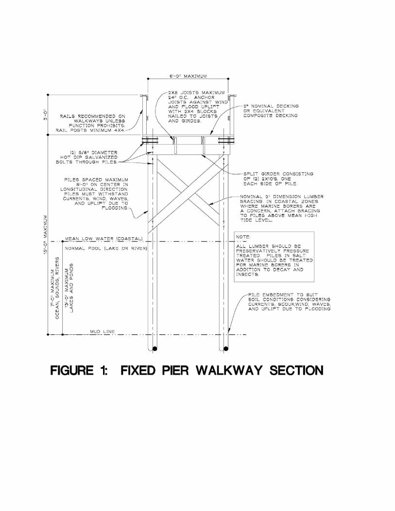


FIGURE 4: GROUND SNOW LOADS Proposed Revision to NC Building Code Proposed Revisions to Chapter 36 (Note: The following is to be considered underlined in its entirety.) CHAPTER 36 DOCKS, PIERS, BULKHEADS AND WATERWAY STRUCTURES SECTION 3601 GENERAL AND SCOPE 3601.1 General. The intent of this chapter is to provide minimum standards for the design, construction and maintenance of docks, piers, bulkheads and waterway structures. The guidelines in this chapter address minimum standards for foundations, design forces, structural integrity, material selection and utilization and construction techniques.
Commentary: The design of docks, piers, bulkheads and waterway structures is essential for the protection of life and property without causing adverse effects to the shoreline. These structures by their very nature result in some modification of physical environment and therefore require minimum design standards.
3601.2 Scope. The following structures shall be designed in accordance with the requirements of this chapter:

1. Docks, piers, gangways and catwalks, other than residential and farm docks and piers exempted from this chapter in the exceptions below, shall be designed by a registered design professional.
2. All bulkheads having an exposed height greater than 5 feet or with a superimposed load shall be designed by a registered design professional and require special inspection. Special inspection shall be waived for bulkheads of any height constructed from property line to property line of one and two family dwellings and including attachment to neighboring bulkheads.
Commentary: Chapters 17 and 18 require special inspection on retaining walls exceeding 5 feet in height due to failures associated with construction related deficiencies. Bulkheads are also prone to the same sort of construction deficiencies; therefore, special inspection is required for bulkheads greater than 5 feet, including common bulkheads for multi-family residential projects or subdivisions where the bulkhead services multiple single family residences. The exception is a bulkhead servicing the property of one single family residence.
3. Oceanfront retaining walls, bulkheads and other types of retaining walls used by the public on the
coastline of the ocean or adjacent inlets shall be designed by a registered design professional.
4. Marine terminal or port facilities for berthing, mooring, docking and servicing ships, barges or tug boats that handle cargo of all types, including bulks, containers, liquids, fuels and people, which shall be designed by a registered design professional in accordance with accepted industry standards.
Commentary: Wharves and piers for cargo handling facilities typically require consideration of loadings unique to each individual facility. As a result, these facilities must be designed by a registered design professional who works with the owner in the preliminary phases of the project to develop design criteria tailored to the owner’s needs. Support structures, such as warehouses, office buildings, and cranes supported on these structures, are required to comply with the provisions of this code. For more information on cargo wharves and docks, the reader is referred to the Department of Defense UFC 4-152-01 Design: Piers and Wharves, UFC 4-152-07 Design: Small Craft Berthing Facilities, and the Port of Long Beach Wharf Design Criteria.
5. Groins not exempted below, jetties, breakwaters, oceanfront seawalls, and oceanfront revetments
which shall be designed by a registered design professional in accordance with accepted industry standards.
Commentary: These structures typically require consideration of loadings unique to each individual facility. As a result, these structures must be designed by a registered design professional who works with the owner in the preliminary phases of the project to develop design criteria tailored to the owner’s needs. For more information, refer to documents such as The Coastal Engineering Manual by the U. S. Army Corps of Engineers.
Exceptions: The following structures are exempt from the requirements of this chapter:
1. Sill structures combined with marsh plantings and certain groins in accordance with the Department of Environmental and Natural Resources general permit requirements.

2. Oceanfront and inlet sandbag revetments in accordance with the Department of Environmental and
Natural Resources general permit requirements.
3. Revetments constructed on single family residential property having a height no greater than 10 feet and slope greater than 1.5 horizontal: 1.0 vertical and in accordance with the Department of Environmental and Natural Resources general permit requirements.
4. Farm structures not on public waters. Commentary: Farm structures should be limited solely for use by the farmer, his family, and his employees.
5. Piers and docks associated with one and two family dwellings meeting the exceptions of the NC Residential Code.
SECTION 3602 DEFINITIONS ADDITIVES. Substances added to a polymer resin or vinyl chloride material to aid in processing the material.
BOAT SLIP. A berthing place for one or two watercraft where the watercraft can be securely moored to cleats, piling, or other devices while the boats are in the water. Boat slips are commonly configured as “side-ties” or as single or double loaded “U” shaped berths.
BULKHEAD. A vertical wall structure designed to retain shoreline material and prevent erosion due to wave activity. CATWALK. A narrow footway platform extending alongside a structure. DESIGN WAVE. A design wave that is potentially most damaging to an economically feasible structure, or wave for which a structure is designed. DOCK. A structure extending alongshore or out from the shore into a body of water, usually accommodating multiple boat slips, to which boats may be moored in order to load or unload people or cargo. EXTRUSION. Manufacturing process whereby a material is pushed through a die to form a shape of constant cross section. Vinyl Chloride sheet piling is generally manufactured using an extrusion process.
FETCH. Open water exposure over which waves are generated. FIBER. One or more glass, carbon, or aramid filaments in the form of a continuous strand or roving in an FRP material.
FIBER ARCHITECTURE. Construction of a composite material from layers with different types and orientations of fibrous material.

FIBER ORIENTATION. Fiber orientation is the alignment of the longitudinal axis of a fiber in an FRP material with respect to the stated reference axis.
FIBER REINFORCED POLYMER (FRP). A composite material which consists of a polymer resin based matrix reinforced with fibers of glass, carbon, aramid, or hybrid combinations of these fiber types.
FIBER VOLUME FRACTION. The volume of reinforcement fiber in a cured composite divided by the volume of the composite section.
FILLER. Substance added to the matrix of a FRP material intended to alter its engineering properties, performance, and/or cost.
GANGWAY. A footway bridge extending from the dock, pier, bulkhead or shore, usually to a floating structure.
GLASS TRANSITION TEMPERATURE (Tg). Temperature at which the polymer matrix of an FRP material changes from a glassy state to a rubbery state.
KING PILE. The primary structural member that supports horizontal panels to form a vertical wall sometimes used in bulkhead or groin construction. LAMINA. A layer of fibers and resin in an FRP material.
MATERIAL LONGITUDINAL DIRECTION. Direction in an FRP material parallel to the direction of pultrusion (pulling) during the manufacture of a plate or structural shape.
MATERIAL TRANSVERSE DIRECTION. Direction in an FRP material orthogonal to the longitudinal direction.
MATRIX. Continuous constituent of an FRP material surrounding the reinforcing fibers and consisting of a polymer resin with any fillers and additives.
PIER. An elevated deck structure, usually pile supported, extending out into the water from the shore. PILE. A timber, concrete, metal, or composite member embedded into the ground to support or brace a structure. “Piles” or “piling” are plural forms of “pile.” PRIVATE WATERFRONT STRUCTURES. A dock, pier, bulkhead, or associated structure not open to the general public and with no more than ten total boat slips and no more than ten owners. PUBLIC WATERFRONT STRUCTURES. A dock, pier, bulkhead, or associated structure located on multi-family residential property (greater than ten dwelling units), public property or commercial property. PULTRUSION. Manufacturing process whereby a material is pulled through a die to form a shape of constant cross section. FRP plates and structural shapes are generally manufactured using a pultrusion process. RESIN. An organic polymer possessing indefinite and often high molecular weight and a softening or melting range that exhibits a tendency to flow when subjected to stress.
REVETMENT. A sloping structure usually constructed of stone or concrete and placed on a shoreline to protect it against erosion by wave and current action. ROVING. In an FRP material a roving is a large number of continuous parallel filaments or a group of untwisted parallel strands. SHEET PILE. A pile with a generally slender flat cross section to be embedded into the ground or seabed and meshed or interlocked with like members to form a diaphragm, wall or bulkhead. SYMMETRIC COMPOSITE. A symmetric composite is a composite material in which the sequence of lamina below the laminate mid-plane is a mirror image to those above the laminate mid-plane. SECTION 3603 PERMITS AND APPROVALS 3603.1 General. In addition to a building permit, permits may be required from federal, state or county agencies such as, but not limited to, the United States Army Corps of Engineers or the Department of Environmental and Natural Resources. In cases of structures to be built on lakes operated by an electric utility for the generation of power, a permit from the operating utility may also be required. SECTION 3604 MINIMUM DESIGN LOADS 3604.1 General. Every structure shall be of sufficient strength to support the imposed dead, live, snow, wind, impact and seismic loads without exceeding the prescribed stresses for the various materials described elsewhere in this code. Adequate consideration shall be made for forces imposed by earth, water, docking and mooring. 3604.2 Dead loads. The weight of the component parts of a structure shall be used in the design when it will influence the strength of the structural elements. All utilities, permanent furniture, dock boxes and mooring hardware should be considered as dead load. 3604.3 Live loads. Design live loads shall be the greatest load that will likely be imposed on the structure, including superimposed loads on retained material which exert horizontal loads on the structure. Where vehicles are allowed, actual weight of vehicles and wheel loads as specified in the latest edition of Standard Specifications for Highway Bridges of the American Association of State Highway and Transportation Officials or obtained from the vehicle manufacturer shall be used. The design load shall be posted at the dock or pier approach where vehicles are allowed. Minimum live loads are:
1. Fixed piers, docks, catwalks - Private waterfront piers: 40 psf or 300 pounds concentrated load on any area 2 foot square. Public waterfront piers: Design loads shall be the greatest combinations of loads exerted on the structure but not less than 60 psf.
2. Floating docks - Private waterfront docks: 20 psf, public waterfront docks: 30 psf, or 300 pounds concentrated load on any area 2 feet square. Under dead and live load, all floating docks shall have a minimum of 3 inches freeboard from the top of the flotation device, other than low freeboard watercraft (e.g. kayak) launching facilities. All floating docks subject to this chapter shall have not
more than 5 degrees tilt from the horizontal under uniform live loading on one-half of the dock width or under concentrated load of 400 pounds applied within 12 inches of any side. 3. Gangways - Gangways shall be designed for a live load of for 100 psf. Flotation for gangway landing shall be designed for 50 psf, live load.
4. Bulkheads, revetments - Design loads shall be the greatest combinations of loads exerted on the structure. Consideration shall be given to horizontal loads exerted by superimposed loads on the retained earth and by inclined surface slopes. Superimposed loads shall be considered when exceeding 50 psf and located within a horizontal distance of three times the height of the bulkhead from the face of the bulkhead.
3604.4 Snow Loads. Design snow loads shall be as prescribed in Chapter 16. 3604.5 Wind loads. Design wind loads shall be as prescribed in Chapter 16 without moored vessels. In wind regions with a design wind speed greater than 90 mph, the design wind speed shall be no less than 90 mph (3 second gust). This gust wind speed shall be adjusted for duration and height (not restricted to 15 feet minimum) for wind pressures applied to vessels moored at the facility in accordance with Chapter 16.
Commentary: During hurricanes, the intent is that vessels be removed from the water or sailed out to sea away from the storm, hence the reduced design wind speed for moored vessels. A design wind speed of 90 mph (3 second gust) is consistent with a thunderstorm.
3604.6 Impact loads. Design impact loads shall be as prescribed in Chapter 16 but not less than 1.25 times the kinetic energy exerted by a striking vessel or vehicle. 3604.7 Seismic Loads. Design seismic loads shall be as prescribed in Chapter 16. Seismic loads are not applicable for any structure exempted from design by a registered design professional. 3604.8 Water loads. Hydrostatic and hydrodynamic loadings shall be considered as follows:
3604.8.1 Hydrostatic Pressures. Hydrostatic pressures shall be considered in conjunction with the equivalent fluid pressure of soil and any surcharge acting on the structure. For bulkheads hydrostatic pressures shall be estimated based on maximum difference between retained and offshore water surface elevations.
3604.8.2 Current Loads. Current loads for structures and vessels shall be determined from records on current velocity using accepted engineering practice.
3604.8.3 Anchorage for Uplift. Sufficient anchorage against uplift between all components, except elements specifically designed to break away shall be provided. Resisting forces shall be not less than 1.5 times the applied uplift force.
3604.8.4 Wave Forces. Wave forces shall be determined from wave records where available. Where no wave records are available, the design wave shall be determined from probable wind speed,

direction, fetch and water depth that will yield a critical wave. Forces shall then be calculated using accepted engineering practice.
3604.8.5 Forces due to Passing Vessels. All piers and floating docks shall be designed for water loading generated by wind and passing vessels. Adjacent to federal designated channels, water loading shall be based on commercial and recreational vessels with minimum passing speeds of 10 and 20 knots, respectively.
3604.9 Earth loads. Lateral earth pressures shall be determined by considering the specific soil properties and applying earth pressure theories generally accepted for soil mechanics in engineering practice. A geotechnical investigation or other adequate consideration shall be given by the registered design professional for the effect of probable varying levels of retained water, tide and flood water. Pressures exerted by the earth shall be checked for dry, moist, and saturated conditions as applicable. 3604.10 Erosion. The effects of reasonably predictable erosion, propeller wash-induced scour, and wave-induced scour shall be given ample consideration. 3604.11 Water Levels. The ability to accommodate dead, live, wind, current and wave loadings for the range of water levels (from low water to base flood level) anticipated at the site shall be given ample consideration. For public and private floating docks, guide piling systems shall be capable of accommodating water levels extending a minimum of 2 feet above base flood elevation plus the freeboard of the dock structure. SECTION 3605 MATERIALS 3605.1 General. The quality of materials and fasteners used for load-supporting purposes shall conform to good engineering practices.
Commentary: Marine environments are quite hostile to many materials. Fresh water facilitates corrosion of metals, and salt water further accelerates corrosion. While conventional concrete cover affords some protection to reinforcing steel, wet service in all marine environments and chloride penetration in salt water environments can break down the passive protection afforded by concrete cover. Wood is subject to attack by decay, insects, and, in salt water, by marine borers. Due to the hostile environments in marine applications, durability of materials is as important a consideration in the selection of materials as strength.
3605.2 Piling and Foundations. Materials used for piling and repairing piling shall comply with applicable provisions of Chapter 18 and the material requirements of Sections 3605.3 through 3605.7.
3605.2.1 Helical Anchors. Helical anchors shall be hot dip galvanized. A representative number of helical anchors subjected to tensile loading shall be load tested in accordance with ASTM D 3689 to two times their design load capacity. Load testing of anchors in tension shall include creep testing of a representative number of the anchors. Helical anchors shall be designed and installed as determined by a registered design professional.
Commentary: The design should consider the risk of varying soils at the site with specific concern for deposits of marine clays susceptible to creep. In sedimentary regions and areas

created with fill from dredged deposits, pockets of such clays can exist and lack of long term testing at that specific location could result in creep of the anchor.
3605.3 Wood. Wood shall be pressure treated with a preservative recommended by the American Wood Preservers’ Association for the specific application. Wood species, preservative treatment, minimum lumber size, and lumber grade shall be in accordance with Table 3605.3. Handrails, guardrails, wallcaps, and decking may be constructed of naturally durable species where located above the normal high water mark.
3605.3.1 Wood Connections. All steel bolts, rods and other hardware shall be hot-dipped galvanized or protected with an equivalent system. All bolts, rods and other metal materials shall be no smaller than 5/8 inch in diameter. Beams, girders or pile caps shall be attached to the piling with a minimum of two 5/8-inch hot-dip galvanized steel bolts per beam member through bolted at each piling connection. Piling shall not be notched so that the cross-section is reduced below 50 percent. Threaded fasteners shall not be tightened directly against wood surfaces but used only in conjunction with standard ogee or flat washers. Cold formed metal connectors shall not be used in wet applications or applications subject to wetting and drying cycles. Mooring hardware, including cleats, and pile guides shall be through bolted using sizes recommended by the manufacturer.

Table 3605.3: SPECIFICATIONS FOR SOUTHERN PINE2 LUMBER IN FRESH AND SALT WATER SERVICE
Location Component AWPA Use Category1,4 Dimensions Lumber Grade Moisture Content at Treatment
Saltwater Freshwater Saltwater Freshwater
Above Normal High Water
Decking3 3B 3B 5/4 “
2” Nominal Min.
Premium
No. 2
Premium
No. 2
Surfaced Dry 19%
Guardrails 3B 3B 2” Nominal Min. No. 2 No. 2 Surfaced Dry 19%
Wallcaps 3B 3B 2” Nominal Min. No. 2 No. 2 Surfaced Dry 19%
Walers 3B 3B 4x6 Nominal No. 2 No. 2 KD 20% or less or Dry 23%
Cross Bracing 3B 3B 2” to 4” Nominal No. 2 No. 2 Surfaced Dry 19%
Splash Zone
Split Pile Caps
4B 4B 2” to 4” Nominal No. 2 No. 2 Surfaced Dry 19%
Stringers 4B 4B 2” Nominal No. 2 No. 2 Surfaced Dry 19%
Below Normal High Water
Sheet Piles 5B 4C 2” to 4” Nominal Marine No. 17 No. 2 Surfaced Dry 19%
Walers 5B 4C 4x6 Nominal Marine No. 17 No. 2 KD 20% or less or Dry 23%
Cross Bracing 5B 4C 2” to 4” Nominal Marine No. 17 No. 2 Surfaced Dry 19%
Rectangular Timber Piles
Not Allowed6
4C 6x6 Nominal Not Allowed6 No. 2 KD 20% or less or Dry 23%
Round Timber Piles
5B6 4C ASTM D25 ASTM D25 ASTM D25 KD 25% or Less

Footnotes:
1. Lumber shall be pressure treated with preservative treatment in accordance with AWPA U1. 2. At the discretion of the Building Official, lumber species other than Southern Pine may be approved when span tables for wet use
conditions are submitted, and the lumber is treated for comparable service life to the treatment specifications required by Table 3605.1. 3. Wood composite decking, treated or untreated, shall provide equivalent service life to the treated decking specified in Table 3605.1. 4. All notches, holes, and field cuts shall be field treated in accordance with AWPA M4. 5. Glulam grade shall be specified as a layup combination or stress class in accordance with the National Design Specification or the
manufacturer’s published data. Layup combinations shall consist of species and grades capable of the treatment retentions equivalent to the AWPA use categories specified in Table 3605.1.
6. Commercial pile wraps may be used to extend the life expectancy of timber piles exposed to marine borers. 7. AWPA requirements for Marine No. 1 specify that no heartwood be exposed on any face prior to preservative treatment.
Commentary: Table 3605.3 specifies the minimum lumber grades and preservative pressure treatment required for Southern Pine lumber to survive in various marine environments providing a reasonable service life. Southern Pine is the most prevalent species treated in North Carolina. Other species are acceptable when treated in accordance with appropriate AWPA standards and designed accounting for wet use. Treatment is specified in accordance with the use condition categories set forth in AWPA U1. Fresh water applications and salt water applications above normal high water require protection from decay and insects. Salt water applications below normal high water require additional protection from marine borers, teredoes and limnoria. In treating wood against marine borers sapwood is required on exposed faces of the pile. For round piles it is reasonably easy to procure a wood member with no heartwood exposed; however, for square or rectangular piles it is much more expensive to saw the pile in a manner that leaves no heartwood exposed on any face of the pile.
Engineered
Lumber
Glulam Timber
5B 4B 4” Nominal Min. Note 5 Note 5 12% Average
Parallel Strand
Lumber
5B 4B 3½” Minimum 1.8E or Better 1.8E or Better Per Manufacturer’s Specifications

3605.4 Concrete. Concrete components shall comply with applicable provisions of Chapter 19 and ACI 318. Minimum concrete strength, air entrainment, maximum chloride content, and maximum water cement ratio shall be determined from ACI 318 on the basis of required structural strength, required resistance to freeze-thaw exposure, required abrasion resistance, and required resistance to water penetration and salt water intrusion. Minimum concrete cover shall be increased and reinforcing steel spacing shall be decreased in accordance with ACI 350, to reduce crack size. All steel embedments, other than reinforcing steel, shall be stainless, hot dip galvanized or coated for corrosion protection. Field welds and abrasions of coatings on embeds shall be touch coated in the field.
Commentary: In marine environments durability requirements dictate material selection and concrete mix designs. ACI 318 specifies maximum water cement ratios for concrete mixes to limit permeability of the concrete. Concrete strength specified by the designer should be consistent with the water cement ratio required. Higher concrete strengths than needed for strength considerations may be required to achieve the required water cement ratio. Controlling cracking of the concrete limits potential pathways of water and chloride ions to the reinforcing steel, thereby reducing corrosion potential.
3605.5 Structural Steel. Steel components shall comply with applicable provisions of Chapter 22 and AISC 360. All structural steel members, fasteners, and fittings shall be protected from corrosion by coating or cathodic protection for the specific exposure. Steel bulkhead components and dock components shall be hot dip galvanized or coated to achieve the corrosion protection required for the degree of exposure of corrosive elements. Field welds and abrasions to coatings shall be touch coated after erection or installation is completed. Cold formed metal joists, girders, columns and studs shall not be used in applications where the members are constantly wet or subject to wetting and drying cycles.
Commentary: Cold formed metal structural members have very little reserve capacity when subjected to a corrosive environment.
3605.6 Aluminum. Aluminum bulkhead sheets or aluminum bulkhead or dock components shall be of proper alloy to resist corrosive elements in the adjacent water and soil. Bulkhead components and hardware shall be aluminum or stainless steel. Aluminum shall be galvanically and physically isolated from concrete and galvanically isolated from steel. Connection hardware and fasteners for aluminum components may be stainless steel or galvanized steel if isolated from aluminum structural elements.
Commentary: Aluminum in contact with concrete may react with the concrete producing deleterious effects on the concrete. Aluminum in direct contact with steel precipitates a galvanic reaction resulting in accelerated corrosion of the steel.
3605.7 Plastics and Composites. Bulkheads, structural shapes, plates, and guardrail systems manufactured from vinyl chloride based materials or fiber reinforced polymer (FRP) materials shall be designed to comply with manufacturer’s published load tables or manufacturer’s published mechanical properties subject to the requirements for specific materials in Sections 3605.7.1, 3605.7.2, and 3605.7.3.

Plastic and composite members shall contain additives to inhibit ultra violet radiation degradation or shall be protected from ultra violet radiation by an appropriate coating.
3605.7.1 Sheet Piling Manufactured from Vinyl Chloride Based Materials. Vinyl chloride materials for sheet piling shall be specified and tested for conformance in accordance with ASTM D4216, including weathering tests in accordance with ASTM D1435. Mechanical properties shall be established in accordance with the tests specified in Table 3605.7.1. Design values of the tabulated properties shall conform to the limiting values specified in the table. The manufacturer of the sheet piling shall produce a certificate of analysis from a third party testing agency certifying the vinyl chloride material from which the sheet piling is manufactured conforms to the physical properties specified. The third party testing agency shall be accredited in accordance with ISO 17025 to conduct the specified tests. Testing programs shall address changes in material sources and composition over time, and test data shall accurately represent the properties of the product produced at any given time.
Commentary: Language of 3605.7.1 and its subsections is based on a 2005 Army Corps of Engineers document entitled “INTERIM REPORT, General Design Guide: PVC Sheet Pile.” This document appears to be the most current available on the topic.
The report explains specification of materials using the cell method of categorizing mechanical properties and conformance testing in accordance with ASTM D4216.
According to the report, manufacturers of PVC sheet piling use primarily recycled materials. Variability of recycled materials affects mechanical properties and durability of the product. For this reason, ongoing testing of the materials used in manufacturing the sheet piling by a qualified third party testing agency is of the utmost importance.
3605.7.1.1 Deflection of Vinyl Chloride Based Sheet Piling. Deflection of vinyl sheet pile bulkheads shall not exceed the lesser of 1/60 times the height from the mud line to the top of the wall or 2 inches. Effects of in-service temperatures exceeding 800F on modulus of elasticity shall be considered in deflection calculations and selection of materials.
Commentary: Vinyl chloride based materials have a very low modulus of elasticity. Consequently, large deflections can occur in bulkheads that normally would have sufficient strength to withstand applied loads. Large deflections affect both stability of the bulkhead, especially in the presence of transient superimposed loads, and appearance. Therefore, deflections need to be limited. The elastic modulus of vinyl chloride based materials decreases at a rate of approximately 202 psi/0F with increase in temperature. Consequently, high summertime temperatures and resulting increased surface temperatures can significantly affect deflection of the bulkhead.
3605.7.1.2 Service Stresses for Vinyl Chloride Based Sheet Piling. Service load stresses in the vinyl sheet piling shall not exceed 3200 psi.

Commentary: Regardless of design method, ASD or LRFD, the USACE report recommends limiting service load stresses to 3200 psi in order to limit creep deformations.
3605.7.1.3 Ultra Violet Light Stabilization. Vinyl chloride based materials shall be compounded with stabilizing agents. Addition of stabilizers during the extrusion process is prohibited.
Commentary: Adding stabilizers during the extrusion process does not adequately stabilize the material against UV deterioration. Stabilizer must be added when the product is compounded.
3605.7.1.4 Impact Resistance of Vinyl Materials. Vinyl sheet pile bulkheads shall have sufficient impact resistance, determined in accordance with ASTM D256 and ASTM D4226, to resist impact from vessels traveling at mooring speeds, resist wave impact when installed in high velocity flood zones (V-Zones on Flood Insurance Rate Maps), and to resist impact from debris likely to collide with the bulkhead at flood stage or in areas subject to storm surge.
3605.7.1.5 Fire, Smoke, and Toxicity. Vinyl materials shall be tested for the in-service thickness in accordance with ASTM D635 with a resulting burning rate of 2 ½ inches per minute or less.
Table 3605.7.1: LIMITATIONS ON MECHANICAL PROPERTIES FOR VINYL CHLORIDE BASED SHEET PILING
Mechanical Property Test Protocol Limitations on Property
Notch Impact Resistance ASTM D256 2.0 ft-lb./in minimum
Drop Dart Impact Resistance, Procedure A ASTM D4226 1.0 in-lb./mil minimum
Drop Dart Impact Resistance, Procedure B ASTM D4226 2.0 in-lb./mil minimum
Tensile Strength ASTM D638 6500 psi minimum
Modulus of Elasticity in Tension ASTM D638 377,000 psi minimum
Deflection Temperature under 264 psi ASTM D648 158 psi minimum
Linear Coefficient of Expansion ASTM D696 4.4x10⁻⁵ in/in/0F maximum
3605.7.2 Pultruded Fiber Reinforced Polymer (FRP) Sheet Piling, Shapes and Plates. Mechanical properties for FRP structural components shall be established in accordance with the tests specified in Table 3605.7.2. Each manufacturer shall publish the characteristic values for the
product in accordance with ASTM D7290. The manufacturer of the FRP shall produce a certificate of analysis certifying the FRP material and constituent materials from which the FRP components are manufactured conform to the physical properties specified. Testing programs shall address changes in material sources and composition over time, and test data shall accurately represent the properties of the product produced at any given time. Manufactured components shall be inspected in the plant in accordance with ASTM D3917 for dimensional tolerances and according to ASTM D4385 for visual defects. Inspection reports shall be provided.
Commentary: Section 3605.7.2 is based on the ASCE “Prestandard for Load and Resistance Factor Design of Pultruded Fiber Reinforced Polymer Structures.” This document has not yet been published as a national standard. Excerpts from the ASCE document necessary to establish consistent material behavior have been reproduced in this code. Methods for proportioning members are left to the designer with reference to manufacturer’s published data.

Table 3605.7.2: LIMITATIONS ON PHYSICAL AND MECHANICAL PROPERTIES FOR FIBER REINFORCED POLYMER
COMPONENTS
Property ASTM Test Method
Minimum Number of Tests
Barcol Hardness D2583 5
Glass Transition Temperature Tg D4065 5
Coefficient of Thermal Expansion D696 5
Moisture Equilibrium Content D570 5
Longitudinal Tensile Strength D638 10
Transverse Tensile Strength D638 10
Longitudinal Tensile Modulus D638 10
Transverse Tensile Modulus D638 10
Longitudinal Compressive Strength D6641 10
Transverse Compressive Strength D6641 10
Longitudinal Compressive Modulus D6641 10
Transverse Compressive Modulus D6641 10
Longitudinal Flexural Strength D790 10
Transverse Flexural Strength D790 10
Longitudinal Flexural Modulus D790 10
Transverse Flexural Modulus D790 10

In-Plane Shear Strength D5379 10
In-Plane Shear Modulus D5379 10
Inter-laminar Shear Strength D2344 10
Longitudinal Pin Bearing Strength D9532 10
Transverse Pin Bearing Strength D9532 10
Pull Through Strength per Fastener
t = 3/8” t = ½” t = ¾”
D7332, Proc. B 10
Footnotes:
1. Property requirements for shapes apply to sheet piles.
2. Tests shall be conducted for material thicknesses, t, tabulated and bolt sizes from 3/8 inch to 1 inch in diameter. No more than 1/3 of the bolt shank within the thickness of the connection material may be threaded. Bolts shall be installed snug tight.
3605.7.2.1 Maximum Service Temperature. Service temperature of FRP structural components shall not exceed Tg-400F, where Tg is the glass transition temperature determined in accordance with ASTM D4065.
3605.7.2.2 FRP Constituent Materials. Fibers and matrix constituents shall comply with the following requirements:
3605.7.2.2.1 Fiber Type. Fibers shall be glass, carbon, aramid, or hybrid combinations of these fiber types. Glass fibers shall conform to ASTM D578.
3605.7.2.2.2 Fiber Architecture and Content. The fiber architecture of any pultruded element comprising the cross section of a pultruded FRP structural member shall be symmetrical and balanced. Each pultruded FRP structural element shall contain a minimum total fiber volume fraction of 30%.
3605.7.2.2.3 Fiber Orientations. Each element of a pultruded FRP structural member shall have fibers oriented in a minimum of two directions separated by a minimum of 30 degrees. In the direction of the longitudinal axis of the member the percentage of continuous fiber in each pultruded element shall be a minimum of 30% of the total fiber reinforcement by volume for shapes and a minimum of 25% of the total fiber reinforcement by volume for plates. When multiple elements share a common edge in the direction of pultrusion, at least 50% of the non-roving reinforcement in the element having the largest percentage of non-roving reinforcement shall extend through the junction connecting the elements.
3605.7.2.2.4 Minimum Fiber Tensile Strength. Determined in accordance with ASTM D7290, the characteristic value of the tensile strength of the fiber strands, yarns, and rovings shall be at least 290,000 psi. Tensile tests shall be conducted in accordance with ASTM D2343.
3605.7.2.2.5 Resin. A commercial grade thermoset resin shall be used for fabricating pultruded FRP structural members.
3605.7.2.2.6 Other Constituent Materials. Additives to the resin system that influence processing or curing, such as fillers, promoter, accelerators, inhibitors, UV resistant agent, and pigments shall be compatible with the fiber and resin system.
3605.7.2.3 Durability and Environmental Effects. Materials for FRP structural components shall be selected, designed, and manufactured to tolerate long term environmental effects anticipated during the service life of the structure.
3605.7.2.3.1 Factors Considered in Material Selection. The following factors shall be considered in selecting FRP materials for marine structures:
a. Performance criteria for the structure; b. Intended service life of the structure; c. Expected environmental conditions, including likelihood of exposure

to alkalis or organic solvents; d. Protective measures; e. Feasibility of maintenance and repair during service.
3605.7.2.3.2 Adjustment of Material Properties to Account for Environmental Effects. Unless the glass transition temperature determined in accordance with ASTM D4065 and the tensile strength of the composite in the longitudinal and transverse directions determined in accordance with ASTM D638, can be shown to retain at least 85% of their characteristic values after conditioning in the environments listed below, the nominal strength and stiffness shall be reduced for design purposes in accordance with test data produced from testing simulating the anticipated environment. Materials that cannot retain at least 15% of their characteristic values after conditioning the listed environments are prohibited in structural applications. Design tensile strength shall be reduced in accordance with material specific tests when in-service temperatures exceed of 900F. Condition test samples as follows:
a. Water: Samples shall be immersed in distilled water having a temperature of 100 + 30F and tested after 1,000 hours of exposure.
b. Alternating Ultraviolet Light and Condensing Humidity: Samples shall be exposed according to Cycle No. 1 (0.89 W/m2/mm, 8 hours UV at 600C, 4 hours condensation at 500C) using UVA-340 lamps in an apparatus meeting the requirements of ASTM G154. Samples shall be tested within two hours after removal from the apparatus.
Commentary: Many FRP materials lose strength and stiffness as a result of environmental exposure. Adjustment of characteristic mechanical properties used in design is necessary to account for effects of exposure. Otherwise, the material may fail prematurely. Exposure to alkalis and freeze thaw may also adversely affect the performance of FRP materials. However, at this time, there are no ASTM protocols specifically for testing FRP materials in these environments. The designer should take these conditions into account when proportioning the structures and specifying FRP materials.
3605.7.2.4 Impact Resistance of FRP Materials. FRP sheet pile bulkheads shall have sufficient impact resistance, determined in accordance with ASTM D7136 for the intended application.
3605.7.2.5 Deflection of FRP Sheet Piling. Deflection of vinyl sheet pile bulkheads shall not exceed the lesser of 1/60 times the height from the mud line to the top of the wall or 2 inches. Effects of in-service temperatures in excess of 900F on modulus of elasticity shall be considered in deflection calculations.
Commentary: FRP materials have a relatively low modulus of elasticity. Consequently, large deflections can occur in bulkheads that normally would have sufficient strength to withstand applied loads. Large deflections affect both stability of the bulkhead, especially in the presence of transient superimposed loads, and appearance. Therefore, deflections need to be limited.

3605.7.2.6 Fire, Smoke, and Toxicity. FRP materials shall be tested for the in-service thickness in accordance with ASTM D635 with a resulting burning rate of 2 ½ inches per minute or less.
Commentary: Criteria are consistent with provisions for CC2 plastics in Section 2606.4. ASTM D4216 references D635 for burning characteristics of vinyl materials, and allusion is made to similar requirements in the ASCE Prestandard for FRP.
3605.7.3 Carbon Fiber Reinforced Polymer Repair Products. Carbon Fiber Reinforced plate and wrap used for flexural and shear reinforcement of existing concrete structures shall be designed in accordance with the design procedures specified in ACI 440.2R. Mechanical properties of Carbon Fiber Reinforced plate and wrap shall be established in accordance with the tests specified in ACI 440.3R.
3605.8 Masonry. Masonry used in bulkheads and dock work shall comply with Chapter 21. SECTION 3606 CONSTRUCTION OF PIERS, DOCKS, CATWALKS, GANGWAYS, AND FLOATING DOCKS 3606.1 Fixed piers. Fixed piers shall be constructed in accordance with Sections 3606.1.1 through 3606.1.4.
3606.1.1 Required depth of piles. Fixed piers shall be supported by pilings with tip penetrations dependent on the soil conditions and the total applied load. Piers support by shallow piling, legs or columns with point bearing on rock shall have provisions to resist horizontal forces and overturning, as well as flotation uplift. Piles shall be installed in accordance with the requirements of Chapter 18 and inspected in accordance with the requirements of Chapter 17. 3606.1.2 Structural steel and concrete members. Structural steel members shall be designed in accordance with AISC 360, Chapter 22 of this code, and the material requirements of this chapter. Concrete members shall be designed in accordance with ACI 318, Chapter 19 of this code, and the materials requirements of this chapter. 3606.1.3 Size of wood piles. Piles shall be sized in accordance with the American Wood Council National Design Specification. In no case shall round timber piles be less than 7 inches in diameter at the butt and have a minimum tip diameter of less than 5 ½ inches. Rectangular timber piles shall not be less than nominal 6 inches x 6 inches. 3606.1.4 Bracing of wood piles. Where required by design, bracing shall be sized to limit stresses in the piles from lateral loads in accordance with the American Wood Council National Design Specification to prevent buckling.

3606.1.5 Wood girder and joist spans. Maximum spans for pier pile caps or girders and joists or stringers shall be determined in accordance with the American Wood Council National Design Specification considering the member to be subject to wet use. 3606.1.6 Connections. Connections between piling or legs to pile caps, stringers, beams, bracing and deck shall have sufficient capacity to safely support all applied loads and provide transfer of load to adjoining members. 3606.1.7 Gangways. On coastal waterways, the maximum slope permitted shall be 3:1 at 0.0 mean low water or above and 2½:1 below 0.0 mean low water. On lakes and other inland waters, the maximum slope shall be 3:1 not less than 90% of the time and 2½:1 not more than 10% of the time.
3606.2 Flotation units. Flotation units shall be foam filled encapsulated floats or polystyrene billets securely wrapped with Class I woven geotextile fabric in accordance with AASHTO M288. The use of metal barrels not specifically designed for use as flotation devices and unwrapped polystyrene billets are prohibited. 3606.3 Electrical service. All electrical service to marine structures shall be in accordance with the North Carolina Electrical Code. 3606.4 Fire protection. All fire protection for marine structures shall be in accordance with applicable provisions of the North Carolina Fire Prevention Code. 3606.5 Fuel docks. Fuel docks and other marine facilities handling flammable liquids shall comply with the Flammable and Combustible Liquids Code, NFPA 30 and the North Carolina Fire Code. All fuel installations shall be designed to prevent fuel spillage from entering the water. The fuel docks or floats shall be isolated to the extent that fire or explosion would have minimal opportunity to spread to or from the fuel dock to the berths. Storage tanks for public facilities shall be located a minimum distance of 50 feet from the dispenser with a shutoff valve at the tank.
Commentary: Other standards typically referenced for fueling facilities are: NFPA 30A–Automotive and Marine Service Station Code NFPA 70–National Electrical Code, Article 555, Marinas and Boatyards NFPA 302–Pleasure and Commercial Motor Craft NFPA 303–Marinas and Boatyards PEI RP1000-09 –Recommended Practices for the Installation of Marina Fueling Systems
3606.6 Guardrails. For walkways, access piers, steps or ramps, guardrails or other safety provisions shall be provided along the edges where the vertical drop to the lesser of the mean low water level , normal low water level (sounds), normal pool (lakes and rivers) or mud line exceeds 6 feet. Edges having a primary function other than walks or access ways, such as docking frontage and swimming access shall not require guardrails. Guardrails shall be designed in accordance with Chapter 16 for balconies. Guardrails

shall be a minimum of 42 inches high and shall prevent the passage of a 21 inch sphere except where required otherwise by Chapter 11. Edge protection shall be provided as required by other regulations.
Commentary: Chapter 36 requirements for guardrails are a compromise intended to address as many general cases as possible. In marine applications, guardrails or deletion of rails may be determined on a case by case basis due to the diversity of activities taking place on the waterfront. In many cases, function and view are important factors in the design of a barrier system. A case in point is an urban waterfront where small to medium sized vessels are docking along a pedestrian promenade. The solution was a minimal barrier system that would allow for function and view while alerting pedestrians that there is a hazard and channeling them away from the hazard. As a compromise, the committee attempted to incorporate these concepts into the draft code provisions. The 21 inch sphere limitation is based from minimum OSHA standards. For a vertical drop less than 6 feet, the intent of omitting guardrails considers that the drop is over water or above a soft substrate. Consideration for guardrails should be made when hazardous conditions exist.
Exception: For private waterfront piers and docks, guardrails or other safety provisions shall be provided along the edges where the vertical drop to the lesser of the mean low water level , normal low water level (sounds), normal pool (lakes and rivers) or mud line exceeds 8 feet. Guardrails shall be a minimum of 36 inches high and shall prevent the passage of a 21 inch sphere. Edge protection shall be provided as required by other regulations.
3606.7 Accessibility. Piers, docks, catwalks, gangways, and floating docks shall comply with Chapter 11 and ANSI/ICC A117.1 for accessibility.
Commentary: Compliance with the NC Building Code does not necessarily ensure compliance with the Federal law, The Americans with Disabilities Act. The designer and the owner should investigate Federal requirements. Refer to Chapter 11 for requirements regarding the number and distribution of accessible berths. The provisions of ANSI A117.1 note the maximum running and cross slopes of the floating dock along the accessible route cannot exceed 1:20 and 1:48, respectively, under static loading (no wave loading). Therefore, the maximum cross slope should be checked with any combination of dead load, uniform dock surface live load and dock surface concentrated load as prescribed in Section 3604.3.2.For maximum running slope on a floating dock, the same loadings must be checked including where the gangway lands on the floating dock at the ends of fingers. ANSI A117.1 provides exceptions to the requirements for maximum running slope, maximum rise and changes in level for gangways serving an accessible route based on the number of boat slips at the facility. The height and location of utilities and attached utility structures must be considered based on the provisions of ANSI A117.1.
3606.8 Egress. Piers and docks shall be provided with means of egress in accordance with Sections 3606.8.1 through 3606.8.4.
3606.8.1 Occupant Load. Occupant load for piers and docks shall be calculated as follows:

3606.8.1.1 Piers and Boardwalks. Occupant load for piers and boardwalks intended for recreational fishing shall be calculated based on 3 linear feet of rail per person on the perimeter plus 50 square feet per person on a net area with a perimeter 3 feet inside the rail. Occupant load for piers and boardwalks intended for other uses shall be in accordance with Chapter 10.
Commentary: Occupants on fishing piers tend to be concentrated around the perimeter of the pier. Depending on the event, occupants on piers intended for assembly purposes can be densely packed over the entire area of the pier.
3606.8.1.2 Public Waterfront Docks. Occupant load for docks constructed a public marinas intended for mooring of private pleasure craft shall be calculated based on 30 square feet of net dock area per person. 3606.8.1.3 Private Waterfront Docks. Occupant load for private waterfront docks shall be calculated based on 20 square feet per person.
Commentary: Private waterfront docks are likely locations for parties, weddings, and other gatherings. The stated occupant load reflects this probability.
3606.8.2 Piers. Piers intended for recreational fishing, assembly, or educational purposes with travel distance to exit discharge exceeding 600 feet and greater than 15 feet above mean low water shall have emergency access ladders at 300 feet intervals and at the end of the pier, and the pier shall be constructed of noncombustible material with the exception that the floor decking may be heavy timber.
Commentary: Emergency access ladders facilitate rescue by watercraft. Noncombustible construction is intended to limit the spread of fire. Heavy timber decking, while combustible, burns more slowly than dimension lumber and offers the designer some advantages in regards to energy absorption from wave forces and durability. Heavy timber decking is defined as solid sawn decking 3 inches nominal in thickness.
3606.8.3 Public Waterfront Docks. Public waterfront docks intended for mooring of private pleasure craft with travel distance to exit discharge in excess of 600 feet shall have a second means of egress or a means of rescue from the water. Construction for these docks shall be noncombustible with the exception that wood walers may be embedded in the dock edges for attachment of mooring hardware.
Commentary: Boat owners may be able to cast off and move away from the dock. Guests may not have this option. Means of rescue by water can be designated harbor patrol, life rafts, or life preservers. Noncombustible construction is intended to slow the spread of fire.
3606.8.4 Buildings Constructed on Piers and Docks. Buildings constructed on public waterfront piers and docks shall comply with the requirements of all applicable provisions of the North Carolina State Building Code.

SECTION 3607 CONSTRUCTION: BULKHEADS AND REVETMENTS 3607.1 Bulkheads. Bulkheads shall be constructed in accordance with Sections 3607.1.1 through 3607.1.5.
3607.1.1 General. Bulkheads shall be constructed in a manner to be effective against erosion and provide for bank stabilization. The bulkhead system may consist of either of the following or combinations thereof: braced sheet pile walls with tie backs, king piles and horizontal panels, gravity walls, cantilever and counterfort retaining walls. Bulkhead walls shall be constructed to prevent passage of fine material (See ASTM D 2487) through joints or cracks from the fill side to the stream side. 3607.1.2 Systems. Local site conditions and performance of bulkheads in service shall govern in selection of a system. The potential for erosion and scour at the mud line shall also be investigated, and compensating features shall be reflected in the construction. Bulkheads shall be terminated by either tying into adjoining structures or by extending the bulkhead line a minimum of 10 feet in a landward direction at an angle of not less than 45 degrees to the shoreline in order to protect against end erosion or flanking by wave action. No structure shall be terminated without regard for end anchorage and stabilization. 3607.1.3 Guardrails. Where designated public walkways, steps or ramps run adjacent to bulkheads within 6 feet, guardrails or other safety provisions shall be provided along the top of the wall where the vertical drop to the lesser of the mean low water level, normal low water level (sounds), normal pool (lakes and rivers) or mud line exceeds 6 feet. Guardrails shall be designed in accordance with Chapter 16 for balcony guardrails. Guardrails shall be 42 inches high and shall prevent the passage of a 21 inch sphere except where required otherwise by Chapter 11. Edge protection shall be provided as required by other regulations. Commentary: Chapter 36 requirements for guardrails are a compromise intended to address as many general cases as possible. In marine applications, guardrails or deletion of rails may be determined on a case by case basis due to the diversity of activities taking place on the waterfront. In many cases, function and view are important factors in the design of a barrier system. A case in point is an urban waterfront where small to medium sized vessels are docking along a pedestrian promenade. The solution was a minimal barrier system that would allow for function and view while alerting pedestrians that there is a hazard and channeling them away from the hazard. As a compromise, the committee attempted to incorporate these concepts into the draft code provisions. The 21 inch sphere limitation is based from minimum OSHA standards. For a vertical drop less than 6 feet, the intent of omitting guardrails considers that the drop is over water or above a soft substrate. Consideration for guardrails should be made when hazardous conditions exist.
Exception: For private waterfront bulkheads with designated walkways within 6 feet, guardrails or other safety provisions shall be provided along the edges where the vertical drop to the lesser of the mean low water level , normal low water level (sounds), normal
pool (lakes and rivers) or mud line exceeds 8 feet. Guardrails shall be a minimum of 36 inches high and shall prevent the passage of a 21 inch sphere. A wall cap 30 inches or less in width shall not be considered a designated walkway unless it is connected to a walkway. Edge protection shall be provided as required by other regulations.
3607.1.4 Wood Construction. For wood grades, member sizes, preservative treatment, and protection of metal fasteners and fittings see Section 3605.3. 3607.1.5 Bulkheads of Materials Other than Wood. Vinyl, fiber reinforced polymer, aluminum, concrete and steel bulkheads shall be constructed in a manner to ensure performance. Connections shall be designed to resist the full applied load. For materials and corrosion protection reference Sections 3605.4 through 3605.7.
3607.2 Revetments. Revetments shall be constructed in accordance with Sections 3607.2.1 through 3607.2.2
3607.2.1 Rigid revetments. Rigid revetments shall be founded on a firm foundation to prevent undermining and progressive instability. Provisions shall be made to provide for adequate toe protection to compensate for known or anticipated scour. Additional protection may be needed in active areas and may consist of sheet piling along the toe or stone rip rap. An adequate pattern of weep holes shall be provided in the face to relieve hydrostatic pressure behind the wall. Joints shall be sealed or provided with a properly designed filter to prevent loss of fines from the protected slope. 3607.2.2 Flexible revetments. Adequate provisions shall be made to prevent migration of fine materials through the structure. The face shall not be steeper than one unit horizontal to one unit vertical. Flatter slopes may be needed for stability depending on the construction materials and site conditions. The face may consist of armor stone, rip rap, or individual interlocking concrete units or poured concrete. Toe protection provisions shall be provided as discussed for the rigid type and the top of slope shall be detailed to prevent erosions under the revetment from surface water runoff. Flexible revetments shall be provided with a filter layer designed to prevent loss of fines from the protected slope and to relieve hydrostatic pressure behind the face.
Commentary: Flexible revetments include geo-textile construction such as sandbags and other geo-textile structures.

Other Proposed Changes to the NC Building Code Proposed Revision to Table 1004.1.1
Add footnote to the table stating the following: Reference Section 3606.8 for occupant load of piers and docks. Proposed Addition to Chapter 11 (Note: The following is to be considered underlined in its entirety.) 1109.14.3.1 Recreational boating facilities. The minimum required number of accessible berths shall be provided as per Table 1109.14.3.1.
1109.14.3.1.1 Number of boat slips not identified. Where the number of boat slips is not identified, such as along the edge of a long side-tie dock for example, each 40 feet of linear dock edge, or fraction thereof, shall be counted as one boat slip.
1109.14.3.1.2 Total number of boat slips. The total number of berths in a marina facility must include all single berths, double berths, side-tie berths, end-tie berths, open berths and covered berths, as well as berths that are components of courtesy landings, visitor docks, fuel docks, sewage pumpout docks, harbor master office docks, haul out and repair docks, etc.
Table 1109.14.3.1 Minimum Required
Number of Accessible Berths
Total Number of Boat Slips
Minimum Number
1 to 25 1
26 to 50 2 51 to 100 3 101 to 150 4 151 to 300 5 301 to 400 6 401 to 500 7 501 to 600 8 601 to 700 9 701 to 800 10 810 to 900 11
901 to 1000 12
1001 and over 12, plus 1 for each 100 or
fraction thereof over 1000

Proposed Revision to Chapter 18
1810.3.2.4.1 Preservative treatment. Timber deep foundation elements used to support permanent structures shall be treated in accordance with this section unless it is established that the tops of the untreated timber elements will be below the lowest ground-water level assumed to exist during the life of the structure. Preservative and minimum final retention shall be in accordance with AWPA U1 (Commodity Specification E, Use Category 4C) for round timber elements and AWPA U1 (Commodity Specification A, Use Category 4B) for sawn timber elements. Preservative-treated timber elements shall be subject to a quality control program administered by an approved agency. Element cutoffs shall be treated in accordance with AWPA M4. For preservative treatment of piles in marine and underwater environments see Chapter 36. Proposed Additions to Chapter 35
AASHTO M288-06 Geotextile Specification for Highway Applications ACI 350-06 Code Requirements for Environmental Engineering Concrete Structures ACI 440.2R-08 Guide to the Design and Construction of Externally Bonded FRP Systems for Strengthening Concrete Structures ACI 440.3R-12 Guide Test Methods for Fiber Reinforced Polymer (FRP) Composites for Reinforcing or Strengthening Concrete and Masonry Structures
ASTM C581-03 Standard Practice for Determining Chemical Resistance of Thermosetting Resins Used in Glass-Fiber-Reinforced Structures Intended for Liquid Service
ASTM C666-03 Standard Test Method for Resistance of Concrete to Rapid Freezing and Thawing
ASTM D256-10 Test Methods for Determining the Izod Pendulum Impact Resistance of Plastics
ASTM D570-98 Standard Test Method for Water Absorption of Plastics
ASTM D578-05 Standard Specification for Glass Fiber Strands
ASTM D618-13 Practice for Conditioning Plastics for Testing
ASTM D638-10 Test Method for Tensile Properties of Plastics
ASTM D648-07 Test Method for Deflection Temperature of Plastics Under Flexural Load in the Edgewise Position
ASTM D696-08 Test Method for Coefficient of Linear Thermal Expansion of Plastics between -300C and 300C with a Vitreous Silica Dilatometer
ASTM D790-10 Standard Test Methods for Flexural Properties of Unreinforced and Reinforced Plastics and Electrical Insulating Materials
ASTM D883-12 Terminology Relating to Plastics
ASTM D907-12a Standard Terminology of Adhesives
ASTM D953-10 Standard Test Method for Bearing Strength of Plastics
ASTM D1435-13 Practice for Outdoor Weathering of Plastics
ASTM D2343-09 Standard Test Method for Tensile Properties of Glass Fiber Strands, Yarns, and Rovings Used in Reinforced Plastics
ASTM D2344-13 Standard Test Method for Short Beam Strength of Polymer Matrix Composite Materials and Their Laminates
ASTM D2583-13a Standard Test Method for Indentation Hardness of Rigid Plastics by Means of a Barcol Impressor
ASTM D3878-07 Standard Terminology of High-modulus Reinforcing Fibers and Their Composites
ASTM D3917-12 Standard Specification for Dimensional Tolerance of Thermosetting Glass-reinforced Plastic Pultruded Shapes
ASTM D4065-12 Standard Practice for Plastics: Dynamic Mechanical Properties: Determination and Report of Procedures
ASTM D4385-13 Standard Practice for Classifying Visual Defects in Thermosetting Reinforced Plastic Pultruded Products
ASTM D4216-13 Standard Test Methods for Impact Resistance of Rigid Poly(Vinyl Chloride) (PVC) Building Products
ASTM D4226-11 Standard Specification for Rigid Poly(Vinyl Chloride) (PVC) and Related PVC and Chlorinated Poly(Vinyl Chloride) (CPVC) Building Products Compounds
ASTM D5379-12 Standard Test Method for Shear Properties of Composite Materials by the V-Notch Beam Method
ASTM D6641-09 Standard Test Method for Determining the Compressive Properties of Polymer Matrix Composite Laminates Using a Combined Loading Compression (CLC) Test Fixture
ASTM D7136-12 Standard Test Method for Measuring the Damage Resistance of a Fiber-reinforced Polymer Matrix Composite to a Drop-weight Impact Event
ASTM D7290-06 Standard Practice for Evaluating Material Property Characteristic Values for Polymeric Composites for Civil Engineering Applications
ASTM D7332-09 Standard Test Method for Measuring the Fastener Pull-through Resistance of a Fiber-reinforced Matrix Composite
ASTM G154-12a Standard Practice for Operating Fluorescent Light Apparatus for UV Exposure of Nonmetallic Materials

Proposed Changes to the NC Fire Prevention Code
Proposed Revision to Section 4504.1 4504.1 General. Piers, marinas and wharves with facilities for mooring or servicing five eleven or more vessels, and marine motor fuel-dispensing facilities shall be equipped with fire protection equipment in accordance with Sections 4504.2 through 4504.6.