normal residual heat removal system (rns) - nrc.gov · rns system purposes 1. remove heat from the...
TRANSCRIPT

Normal Residual Heat Normal Residual Heat
AP1000 Technology Section 6.1AP1000 Technology Section 6.1
11
Removal System (RNS)Removal System (RNS)
Learning ObjectivesLearning Objectives1. State the purpose of the Normal Residual
Heat Removal System (RNS).
2. Describe the major differences between the AP1000 RNS and current operating W ti h l t R id l H t
22
Westinghouse plants Residual Heat Removal (RHR) System.
RNS System PurposesRNS System Purposes1.1. Remove heat from the core and the RCS during Remove heat from the core and the RCS during
shutdown operations. shutdown operations.
2.2. Provide RCS and refueling cavity purification flow to Provide RCS and refueling cavity purification flow to CVCS during refueling operations. CVCS during refueling operations.
3.3. Provide cooling for the inProvide cooling for the in--containment refueling containment refueling water storage tank.water storage tank.
33
water storage tank.water storage tank.
4.4. Provide low pressure makeup to the reactor coolant Provide low pressure makeup to the reactor coolant system. system.
5.5. Remove heat from the core and the RCS following Remove heat from the core and the RCS following successful mitigation of an accident by the passive successful mitigation of an accident by the passive core cooling system.core cooling system.

RNS System Purposes (cont.)RNS System Purposes (cont.)6.6. Provide low temperature overpressure protection Provide low temperature overpressure protection
(LTOP) for the RCS during refueling, startup, and (LTOP) for the RCS during refueling, startup, and shutdown operations. shutdown operations.
7.7. Provide longProvide long--term, postterm, post--accident makeup accident makeup flowpathflowpath to to the containment inventory.the containment inventory.
88 Provide backup for cooling the spent fuel poolProvide backup for cooling the spent fuel pool
44
8.8. Provide backup for cooling the spent fuel pool.Provide backup for cooling the spent fuel pool.

Shutdown CoolingShutdown Cooling• The RNS reduces the temperature of the
reactor coolant system from 350° to 125°F within 96 hours after shutdown.
• The system maintains the RCS temperature at or below 125°F for the plant shutdown
55
or below 125°F for the plant shutdown.
• First phase of cooldown performed by primary-to-secondary heat transfer reduces the RCS temperature to less than or equal to 350°F and 450 psig.

RNS Shutdown CoolingRNS Shutdown Cooling
•• 11stst Phase of cooldown takes 4 hrs.Phase of cooldown takes 4 hrs.
•• RNS placed I/S at 350RNS placed I/S at 350°°F and 450 psig.F and 450 psig.
•• RNS is designed to reduce RCS temperature RNS is designed to reduce RCS temperature
66
S s des g ed o educe CS e pe a u eS s des g ed o educe CS e pe a u efrom 350 to 125from 350 to 125°°F within 96 hours.F within 96 hours.
•• With only one train I/S RNS can still perform With only one train I/S RNS can still perform this task, it just takes longer.this task, it just takes longer.
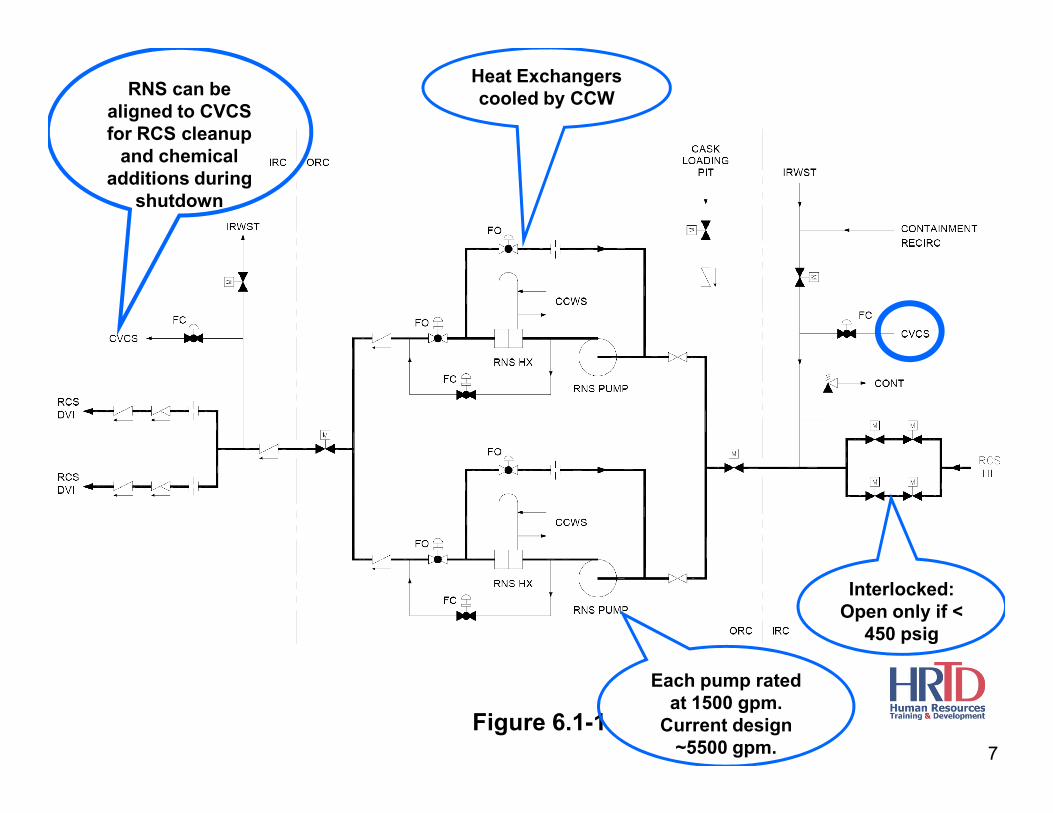
RNS can be aligned to CVCS for RCS cleanup
and chemical additions during
shutdown
Heat Exchangers cooled by CCW
7
Figure 6.1-1
Each pump rated at 1500 gpm.
Current design ~5500 gpm.
Interlocked:Open only if <
450 psig

RNS RNS HxHx ArrangementArrangement
88

Figure 6.1-1
1
2
9
To perform cooldown and control temperature operatoradjusts the positions of valves 1, 2, 3, & 4.
By bypassing flow trough the RNS Hx Cooldown (& heatup) rates can be changed.
3
4

10
Figure 6.1-1
Provides low-temperature overpressure
protection of the RCS.

Provides cooling for IRWSTWhen needed
More later
11Figure 6.1-2

Design Features Addressing Intersystem LOCADesign Features Addressing Intersystem LOCA((SECY 90SECY 90--016 )016 )
•• Portions of RNS from the RCS to the outside containment Portions of RNS from the RCS to the outside containment iso valves are designed to RCS operating pressure. iso valves are designed to RCS operating pressure.
•• The isolation valve in the pump suction line from the RCS The isolation valve in the pump suction line from the RCS is designed to the RCS pressure. is designed to the RCS pressure.
1212
•• Relief valve in the high pressure portion of the pump Relief valve in the high pressure portion of the pump suction line reduces the risk of overpressurizing the low suction line reduces the risk of overpressurizing the low pressure portions of the system. pressure portions of the system.
•• Suction isolation valves are interlocked to prevent their Suction isolation valves are interlocked to prevent their
opening at RCS pressures above 450 psig.opening at RCS pressures above 450 psig.

Piping designed forRCS pressure
Piping designed forRCS pressure
Piping designed for900 psi
13
Figure 6.1-1

Design Features Addressing Shutdown and MidDesign Features Addressing Shutdown and Mid--Loop Operations (GL 88Loop Operations (GL 88--17)17)
•• RCS hot legs and cold legs are vertically offset.RCS hot legs and cold legs are vertically offset.
•• StepStep--nozzle connection to the RCS hot leg.nozzle connection to the RCS hot leg.
•• The RNS pumps are designed to minimize The RNS pumps are designed to minimize
1414
ggsusceptibility to susceptibility to cavitationcavitation..
•• SelfSelf--Venting Suction Line.Venting Suction Line.
•• WR pressure and hot leg level instrumentation.WR pressure and hot leg level instrumentation.

Figure 6.1-3
15
The RNS header is continuously sloped from the RCS hot leg to the pump suction. This eliminates local high points where air/gas could collect and cause low net positive suction head, pump binding and a loss of residual heat removal capability.
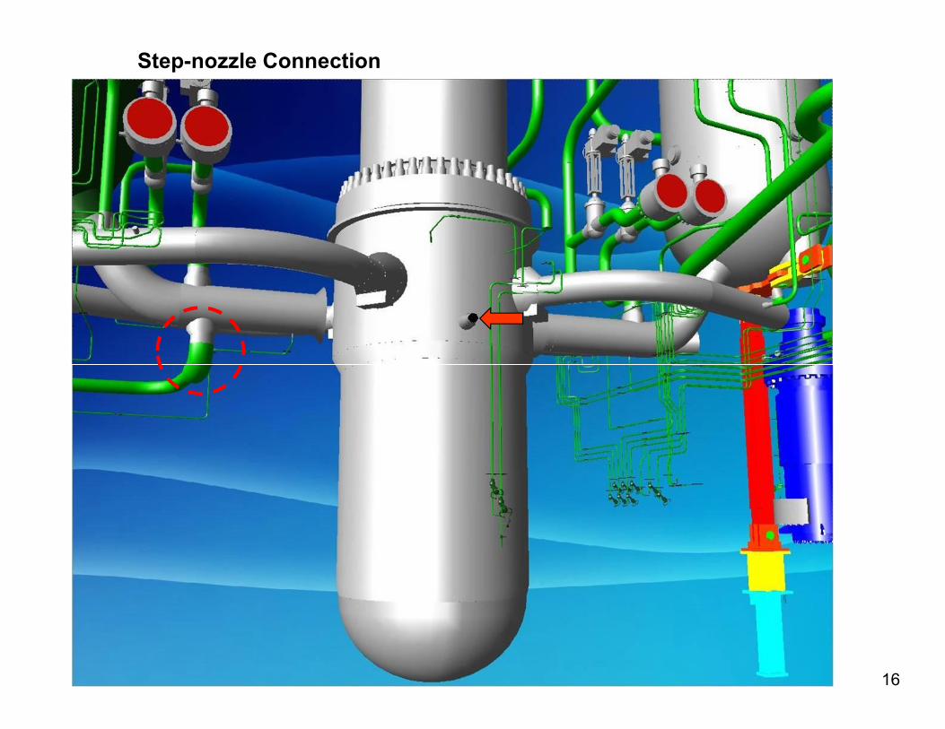
Step-nozzle Connection
16

Questions?Questions?
1717

Which one of the following is Which one of the following is NOTNOTa function of RNS?a function of RNS?
A.A. Removes decay heat when < 350Removes decay heat when < 350°°F in F in RCS.RCS.
B.B. Provides high pressure injection during Provides high pressure injection during accidentsaccidents
1818
accidents.accidents.
C.C. Provides cooling for the IC RWST.Provides cooling for the IC RWST.
D.D. Provides a flowpath for RCS cleanup Provides a flowpath for RCS cleanup during shutdown operations.during shutdown operations.

When RNS is operated in the When RNS is operated in the decay heat removal mode, it takes decay heat removal mode, it takes
a suction on _______ and a suction on _______ and discharges to ____________.discharges to ____________.
AA the IC RWST the RCS hot legsthe IC RWST the RCS hot legs
1919
A.A. the IC RWST, the RCS hot legsthe IC RWST, the RCS hot legs
B.B. an RCS hot leg, the Rx vesselan RCS hot leg, the Rx vessel
C.C. an RCS cold leg, the Rx Vesselan RCS cold leg, the Rx Vessel
D.D. the IC RWST, the RCS cold legsthe IC RWST, the RCS cold legs

One feature that protects the RNS One feature that protects the RNS against over pressurization is…against over pressurization is…
A.A. Auto closure of RNS discharge valves on Auto closure of RNS discharge valves on high RCS pressure.high RCS pressure.
B.B. A power operated relief valve (PORV) on A power operated relief valve (PORV) on the RNS suction linethe RNS suction line
2020
the RNS suction line.the RNS suction line.
C.C. Interlock to prevent the opening of RNS Interlock to prevent the opening of RNS suction valves when RCS pressure is high.suction valves when RCS pressure is high.
D.D. The RNS minimum flow bypass line.The RNS minimum flow bypass line.