norma_4000 5000
TRANSCRIPT
®
NORMA 4000/5000 Power Analyzer
Operators Manual
PN 2842188 June 2007 © 2007 Fluke Corporation, All rights reserved. Printed in the Netherlands. All product names are trademarks of their respective companies.

LIMITED WARRANTY AND LIMITATION OF LIABILITY Each Fluke product is warranted to be free from defects in material and workmanship under normal use and service. The warranty period is two years and begins on the date of shipment. Parts, product repairs, and services are warranted for 90 days. This warranty extends only to the original buyer or end-user customer of a Fluke authorized reseller, and does not apply to fuses, disposable batteries, or to any product which, in Fluke's opinion, has been misused, altered, neglected, contaminated, or damaged by accident or abnormal conditions of operation or handling. Fluke warrants that software will operate substantially in accordance with its functional specifications for 90 days and that it has been properly recorded on non-defective media. Fluke does not warrant that software will be error free or operate without interruption.
Fluke authorized resellers shall extend this warranty on new and unused products to end-user customers only but have no authority to extend a greater or different warranty on behalf of Fluke. Warranty support is available only if product is purchased through a Fluke authorized sales outlet or Buyer has paid the applicable international price. Fluke reserves the right to invoice Buyer for importation costs of repair/replacement parts when product purchased in one country is submitted for repair in another country.
Fluke's warranty obligation is limited, at Fluke's option, to refund of the purchase price, free of charge repair, or replacement of a defective product which is returned to a Fluke authorized service center within the warranty period.
To obtain warranty service, contact your nearest Fluke authorized service center to obtain return authorization information, then send the product to that service center, with a description of the difficulty, postage and insurance prepaid (FOB Destination). Fluke assumes no risk for damage in transit. Following warranty repair, the product will be returned to Buyer, transportation prepaid (FOB Destination). If Fluke determines that failure was caused by neglect, misuse, contamination, alteration, accident, or abnormal condition of operation or handling, including overvoltage failures caused by use outside the product’s specified rating, or normal wear and tear of mechanical components, Fluke will provide an estimate of repair costs and obtain authorization before commencing the work. Following repair, the product will be returned to the Buyer transportation prepaid and the Buyer will be billed for the repair and return transportation charges (FOB Shipping Point).
THIS WARRANTY IS BUYER'S SOLE AND EXCLUSIVE REMEDY AND IS IN LIEU OF ALL OTHER WARRANTIES, EXPRESS OR IMPLIED, INCLUDING BUT NOT LIMITED TO ANY IMPLIED WARRANTY OF MERCHANTABILITY OR FITNESS FOR A PARTICULAR PURPOSE. FLUKE SHALL NOT BE LIABLE FOR ANY SPECIAL, INDIRECT, INCIDENTAL OR CONSEQUENTIAL DAMAGES OR LOSSES, INCLUDING LOSS OF DATA, ARISING FROM ANY CAUSE OR THEORY.
Since some countries or states do not allow limitation of the term of an implied warranty, or exclusion or limitation of incidental or consequential damages, the limitations and exclusions of this warranty may not apply to every buyer. If any provision of this Warranty is held invalid or unenforceable by a court or other decision-maker of competent jurisdiction, such holding will not affect the validity or enforceability of any other provision.
Fluke Corporation P.O. Box 9090 Everett, WA 98206-9090 U.S.A.
Fluke Europe B.V. P.O. Box 1186 5602 BD Eindhoven The Netherlands
11/99
To register your product online, visit register.fluke.com

BEGRENZTE GEWÄHRLEISTUNG UND HAFTUNGSBESCHRÄNKUNG Fluke gewährleistet, daß jedes Fluke-Produkt unter normalem Gebrauch und Service frei von Material- und Fertigungsdefekten ist. Die Garantiedauer beträgt 2 Jahre ab Versanddatum. Die Garantiedauer für Teile, Produktreparaturen und Service beträgt 90 Tage. Diese Garantie wird ausschließlich dem Ersterwerber bzw. dem Endverbraucher geleistet, der das betreffende Produkt von einer von Fluke autorisierten Verkaufsstelle erworben hat, und erstreckt sich nicht auf Sicherungen, Einwegbatterien oder andere Produkte, die nach dem Ermessen von Fluke unsachgemäß verwendet, verändert, verschmutzt, vernachlässigt, durch Unfälle beschädigt oder abnormalen Betriebsbedingungen oder einer unsachgemäßen Handhabung ausgesetzt wurden. Fluke garantiert für einen Zeitraum von 90 Tagen, daß die Software im wesentlichen in Übereinstimmung mit den einschlägigen Funktionsbeschreibungen funktioniert und daß diese Software auf fehlerfreien Datenträgern gespeichert wurde. Fluke übernimmt jedoch keine Garantie dafür, daß die Software fehlerfrei ist und störungsfrei arbeitet.
Von Fluke autorisierte Verkaufsstellen werden diese Garantie ausschließlich für neue und nicht benutzte, an Endverbraucher verkaufte Produkte leisten. Die Verkaufsstellen sind jedoch nicht dazu berechtigt, diese Garantie im Namen von Fluke zu verlängern, auszudehnen oder in irgendeiner anderen Weise abzuändern. Der Erwerber hat nur dann das Recht, aus der Garantie abgeleitete Unterstützungsleistungen in Anspruch zu nehmen, wenn er das Produkt bei einer von Fluke autorisierten Vertriebsstelle gekauft oder den jeweils geltenden internationalen Preis gezahlt hat. Fluke behält sich das Recht vor, dem Erwerber Einfuhrgebühren für Ersatzteile in Rechnung zu stellen, wenn dieser das Produkt in einem anderen Land zur Reparatur anbietet, als dem Land, in dem er das Produkt ursprünglich erworben hat.
Flukes Garantieverpflichtung beschränkt sich darauf, daß Fluke nach eigenem Ermessen den Kaufpreis ersetzt oder aber das defekte Produkt unentgeltlich repariert oder austauscht, wenn dieses Produkt innerhalb der Garantiefrist einem von Fluke autorisierten Servicezentrum zur Reparatur übergeben wird.
Um die Garantieleistung in Anspruch zu nehmen, wenden Sie sich bitte an das nächstgelegene und von Fluke autorisierte Servicezentrum, um Rücknahmeinformationen zu erhalten, und senden Sie dann das Produkt mit einer Beschreibung des Problems und unter Vorauszahlung von Fracht- und Versicherungskosten (FOB Bestimmungsort) an das nächstgelegene und von Fluke autorisierte Servicezentrum. Fluke übernimmt keine Haftung für Transportschäden. Im Anschluß an die Reparatur wird das Produkt unter Vorauszahlung von Frachtkosten (FOB Bestimmungsort) an den Erwerber zurückgesandt.Wenn Fluke jedoch feststellt, daß der Defekt auf Vernachlässigung, unsachgemäße Handhabung, Verschmutzung, Veränderungen am Gerät, einen Unfall oder auf anormale Betriebsbedingungen, einschließlich durch außerhalb der für das Produkt spezifizierten Belastbarkeit verursachten Überspannungsfehlern, zurückzuführen ist, wird Fluke dem Erwerber einen Voranschlag der Reparaturkosten zukommen lassen und erst die Zustimmung des Erwerbers einholen, bevor die Arbeiten begonnen werden. Nach der Reparatur wird das Produkt unter Vorauszahlung der Frachtkosten an den Erwerber zurückgeschickt, und es werden dem Erwerber die Reparaturkosten und die Versandkosten (FOB Versandort) in Rechnung gestellt.
DIE VORSTEHENDEN GARANTIEBESTIMMUNGEN STELLEN DEN EINZIGEN UND ALLEINIGEN RECHTSANSPRUCH AUF SCHADENERSATZ DES ERWERBERS DAR UND GELTEN AUSSCHLIESSLICH UND AN STELLE VON ALLEN ANDEREN VERTRAGLICHEN ODER GESETZLICHEN GEWÄHRLEISTUNGSPFLICHTEN, EINSCHLIESSLICH - JEDOCH NICHT DARAUF BESCHRÄNKT - DER GESETZLICHEN GEWÄHRLEISTUNG DER MARKTFÄHIGKEIT, DER GEBRAUCHSEIGNUNG UND DER ZWECKDIENLICHKEIT FÜR EINEN BESTIMMTEN EINSATZ.FLUKE HAFTET NICHT FÜR SPEZIELLE, UNMITTELBARE, MITTELBARE, BEGLEIT- ODER FOLGESCHÄDEN ODER VERLUSTE, EINSCHLIESSLICH VERLUST VON DATEN, UNABHÄNGIG VON DER URSACHE ODER THEORIE.
Angesichts der Tatsache, daß in einigen Ländern die Begrenzung einer gesetzlichen Gewährleistung sowie der Ausschluß oder die Begrenzung von Begleit- oder Folgeschäden nicht zulässig ist, kann es sein, daß die obengenannten Einschränkungen und Ausschlüsse nicht für jeden Erwerber gelten.Sollte eine Klausel dieser Garantiebestimmungen von einem zuständigen Gericht oder einer anderen Entscheidungsinstanz für unwirksam oder nicht durchsetzbar befunden werden, so bleiben die Wirksamkeit oder Durchsetzbarkeit irgendeiner anderen Klausel dieser Garantiebestimmungen von einem solchen Spruch unberührt.
11/99
LIMITES DE GARANTIE ET DE RESPONSABILITE La société Fluke garantit l’absence de vices de matériaux et de fabrication de ses produits dans des conditions normales d’utilisation et d’entretien. La période de garantie est de deux ans et prend effet à la date d’expédition. Les pièces, les réparations de produit et les services sont garantis pour une période de 90 jours. Cette garantie ne s’applique qu’à l’acheteur d’origine ou à l’utilisateur final s’il est client d’un distributeur agréé par Fluke, et ne couvre pas les fusibles, les batteries/piles interchangeables ni aucun produit qui, de l’avis de Fluke, a été malmené, modifié, négligé, contaminé ou endommagé par accident ou soumis à des conditions anormales d’utilisation et de manipulation. Fluke garantit que le logiciel fonctionnera en grande partie conformément à ses spécifications fonctionnelles pour une période de 90 jours et qu’il a été correctement enregistré sur des supports non défectueux. Fluke ne garantit pas que le logiciel est exempt d’erreurs ou qu’il fonctionnera sans interruption.
Les distributeurs agréés par Fluke appliqueront cette garantie à des produits vendus neufs et qui n’ont pas servi, mais ils ne sont pas autorisés à offrir une garantie plus étendue ou différente au nom de Fluke. Le support de garantie est offert uniquement si le produit a été acheté à un point de vente agréé par Fluke ou bien si l’acheteur a payé le prix international applicable. Fluke se réserve le droit de facturer à l’acheteur les frais d’importation des pièces de réparation ou de remplacement si le produit acheté dans un pays a été expédié dans un autre pays pour y être réparé.
L’obligation de garantie de Fluke est limitée, au choix de Fluke, au remboursement du prix d’achat, ou à la réparation/remplacement gratuit d’un produit défectueux retourné dans le délai de garantie à un centre de service agréé par Fluke.
Pour avoir recours au service de la garantie, mettez-vous en rapport avec le centre de service agréé Fluke le plus proche pour recevoir les références d’autorisation de renvoi, puis envoyez le produit, accompagné d’une description du problème, port et assurance payés (franco lieu de destination), à ce centre de service. Fluke décline toute responsabilité en cas de dégradations survenues au cours du transport. Après une réparation sous garantie, le produit sera retourné à l’acheteur, en port payé (franco lieu de destination). Si Fluke estime que le problème a été causé par une négligence, un mauvais traitement, une contamination, une modification, un accident ou des conditions de fonctionnement ou de manipulation anormales, notamment de surtensions liées à une utilisation du produit en dehors des spécifications nominales, ou de l’usure normale des composants mécaniques, Fluke fournira un devis des frais de réparation et ne commencera la réparation qu’après en avoir reçu l’autorisation. Après la réparation, le produit sera renvoyé à l’acheteur, en port payé (franco point d’expédition) et les frais de réparation et de transport lui seront facturés.
LA PRÉSENTE GARANTIE EST EXCLUSIVE ET TIENT LIEU DE TOUTES AUTRES GARANTIES, EXPRESSES OU IMPLICITES, Y COMPRIS, MAIS NON EXCLUSIVEMENT, TOUTE GARANTIE IMPLICITE DE VALEUR MARCHANDE OU D’ADÉQUATION À UN USAGE PARTICULIER. FLUKE NE POURRA ETRE TENU RESPONSABLE D’AUCUN DOMMAGE PARTICULIER, INDIRECT, ACCIDENTEL OU CONSECUTIF, NI D’AUCUN DEGAT OU PERTE, DE DONNEES NOTAMMENT, SUR UNE BASE CONTRACTUELLE, EXTRA-CONTRACTUELLE OU AUTRE.
Etant donné que certains pays ou états n’admettent pas les limitations d’une condition de garantie implicite, ou l’exclusion ou la limitation de dégâts accidentels ou consécutifs, il se peut que les limitations et les exclusions de cette garantie ne s’appliquent pas à chaque acheteur. Si une disposition quelconque de cette garantie est jugée non valide ou inapplicable par un tribunal ou un autre pouvoir décisionnel compétent, une telle décision n’affectera en rien la validité ou le caractère exécutoire de toute autre disposition.
11/99
有限保证和责任限制 在正常使用和维护条件下,Fluke公司保证每一个产品都没有材料缺陷和制造工艺问题。保证期为从产品发货之日起二年。部件、产品修理和服务的保证期限为 90 天。本项保证仅向授权零售商的原始买方或最终用户 提供,并且不适用于保险丝和一次性电池或者任何被 Fluke 公司认定由于误用、改变、疏忽、意外、非正 常操作和使用所造成的产品损坏。Fluke 公司保证软件能够在完全符合性能指标的条件下至少操作 90 天, 而且软件是正确地记录在无缺陷的媒体上。Fluke公司并不保证软件没有错误或无操作中断。
Fluke公司仅授权零售商为最终客户提供新产品或未使用过产品的保证。但并未授权他们代表 Fluke 公司提供 范围更广或内容不同的保证。只有通过 Fluke 授权的销售商购买的产品,或者买方已经按适 当的国际价格 付款的产品,才能享受 Fluke 的保证支持。在一个国家购买的产品被送往另一个国家维修时,Fluke 公司保 留向买方收取修理/更换零部件的进口费用的权利。
Fluke公司的保证责任是有限的,Fluke公司可以选择是否将依购买价退款、免费维修或更换在保证期内退回到Fluke公司委托服务中心的有缺陷产品。
要求保修服务时,请与就近的 Fluke 授权服务中心联系,获得退还授权信息;然后将产品连同问题描述寄至 该服务中心,并预付邮资和保险费用(目的地离岸价格)。Fluke 对运送途中发生的损坏不承担责任。在保 修之后,产品将被寄回给买方并提前支付运输费(目的地交货)。如果 Fluke 认定产品故障是由于疏忽、 滥用、污染、修改、意外或不当操作或处理状况而产生,包含使用超出产品特的特定额定值而导致过电压故 障,或是由于机件日常使用耗损,则Fluke会估计修理费用,在实际修理之前先获得买方同意。在修理之后,产品将被寄回给买方并预付运输费;买方将收到修理和返程运输费用(寄发地交货)的帐单。
本保证为买方唯一能获得的全部赔偿内容,并且取代所有其它明示或隐含的保证,包括但不限于适销性或适用于特殊目的的任何隐含保证。FLUKE 不应对由于任何原因或推理所发生的任何特殊、间接、偶发或后续的 损坏或损失承担赔偿责任,包括数据丢失。
由于某些国家或州不允许对隐含保证的期限加以限制、或者排除和限制意外或后续损坏,本保证的限制和排除责任条款可能并不对每一个买方都适用。如果本保证的某些条款被法院或其它具有适当管辖权的裁决机构判定为无效或不可执行,则此类判决将不影响任何其它条款的有效性或可执行性。
11/99

i
Table of Contents
Chapter Title Page
1 About this Document .......................................................................... 1-1
Signs and Symbols............................................................................................. 1-3 Transport and Storage........................................................................................ 1-3
Transport ....................................................................................................... 1-3 Storage........................................................................................................... 1-3
Recalibration...................................................................................................... 1-3 Maintenance....................................................................................................... 1-3 Decommissioning and Disposal......................................................................... 1-4
Shutting Down............................................................................................... 1-4 Recycling and Disposal ................................................................................. 1-4 Housing ......................................................................................................... 1-4 Electronic Components ................................................................................. 1-4
2 General Safety Instructions................................................................ 2-1 Introduction........................................................................................................ 2-3 Protection Class ................................................................................................. 2-3 Qualified Personnel............................................................................................ 2-3 Safe Operation ................................................................................................... 2-3 Proper Use.......................................................................................................... 2-3 Warranty ............................................................................................................ 2-3 Electrical Connections ....................................................................................... 2-4 Risks During Operation ..................................................................................... 2-4 Maintenance and Repairs................................................................................... 2-4 Accessories ........................................................................................................ 2-4 Shutting Down ................................................................................................... 2-4 Safety Instructions on the Device Housing........................................................ 2-5
Mains Connection.......................................................................................... 2-5 Input Voltage and Maintenance..................................................................... 2-5 Indoor Use Only ............................................................................................ 2-5
3 Design and Functions......................................................................... 3-1 About this Chapter ............................................................................................. 3-3 Terminals (Back) ............................................................................................... 3-3 Operating Controls and Display......................................................................... 3-4
NORMA 4000/5000 Operators Manual
ii
Navigation and Measuring Keys ................................................................... 3-5 Navigation through Display .......................................................................... 3-6 Overview of Function Keys........................................................................... 3-6
Functions............................................................................................................ 3-7
4 Startup.................................................................................................. 4-1 Taking Inventory................................................................................................ 4-3 Installation and Switching On............................................................................ 4-3
Installation ..................................................................................................... 4-3 Switching Device On..................................................................................... 4-3 Switching Device Off .................................................................................... 4-4
5 Connection to Circuits ........................................................................ 5-1 Before You Begin .............................................................................................. 5-3 Connecting Sequence......................................................................................... 5-3 Overview............................................................................................................ 5-4 1-Phase Measurement ........................................................................................ 5-4
Direct Connection.......................................................................................... 5-4 Measurement with Shunt ............................................................................... 5-5 Measuring with Voltage and Current Transducer ......................................... 5-6
Aron Circuit (Triaxial/Guard Technique) .......................................................... 5-7 Direct Connection.......................................................................................... 5-7 Measuring with Shunt.................................................................................... 5-8 With Voltage and Current Transducer........................................................... 5-9
3-Phase Measurement in 4-Wire System........................................................... 5-10 Direct Connection.......................................................................................... 5-10 Measuring with Shunt.................................................................................... 5-11
6 Simple Measurement .......................................................................... 6-1 About this Chapter ............................................................................................. 6-3 Connection to Circuits ....................................................................................... 6-3 Configuration ..................................................................................................... 6-3 Measuring .......................................................................................................... 6-3
7 Configuration....................................................................................... 7-1 Set Up for Measuring......................................................................................... 7-3 Configuration 1:W3 ........................................................................................... 7-3 Five Steps........................................................................................................... 7-4 Call up General Setup and System Information Screen..................................... 7-4
General Setup ................................................................................................ 7-4 System Information Screen ........................................................................... 7-4
Load Configuration............................................................................................ 7-5 Load Configuration (Optional)...................................................................... 7-5 Modify Loaded Configurations ..................................................................... 7-5
Configure Data Transfer to Printer and PC........................................................ 7-5 Configure External Printer ............................................................................ 7-6 Configure Interface to PC.............................................................................. 7-7 Configure RS 232 .......................................................................................... 7-7 Configure GPIB Address............................................................................... 7-8 Configure Ethernet ........................................................................................ 7-8
Configure Average Time and Synchronization ................................................. 7-9 Timing & Sync Setup .................................................................................... 7-9 Set Average Time .......................................................................................... 7-10
Contents (continued)
iii
Select Synchronization Source ...................................................................... 7-11 Set Trigger Level ........................................................................................... 7-11 Select Slope Direction ................................................................................... 7-12 Select Low-Pass Filter ................................................................................... 7-12 Configure Signal Output................................................................................ 7-12
Adjust Date and Time ........................................................................................ 7-13 Configure Current and Voltage Channels.......................................................... 7-13
Current Channel Setup .................................................................................. 7-14 Configure Input Range .................................................................................. 7-15
Automatic Range Adjustment (Auto) ....................................................... 7-15 Manual Range Adjustment (Range).......................................................... 7-15
Configure Scale ............................................................................................. 7-15 Configure Coupling ....................................................................................... 7-16 Configure Filter ............................................................................................. 7-17 Voltage Channel Setup .................................................................................. 7-17
Switch Current Input to External Input (BNC).................................................. 7-18 Switch Current Input ..................................................................................... 7-18 Configure Auto-Range Selection................................................................... 7-18 Configure Scale ............................................................................................. 7-18
Integration Function Configuration ................................................................... 7-19 Integration Setup ........................................................................................... 7-19 Select Integration Value ................................................................................ 7-21 Configure Status ............................................................................................ 7-21 Configure Start .............................................................................................. 7-22 Configure Stop............................................................................................... 7-23
Save Configuration ............................................................................................ 7-23 Delete Configuration.......................................................................................... 7-24 Undersampling and Aliasing.............................................................................. 7-24
8 Measuring Process ............................................................................. 8-1 Introduction........................................................................................................ 8-3 Prior to Measuring ............................................................................................. 8-3
Measuring with Default Configuration.......................................................... 8-3 Measuring with User-Defined Configuration................................................ 8-3
Measure Voltage, Current and Power................................................................ 8-4 Measured Values for Individual Channels .................................................... 8-4
View the Values of One Channel.............................................................. 8-4 View Detailed Values of One Channel ..................................................... 8-4
View Totals of all Measured Values ............................................................. 8-7 View Totals ............................................................................................... 8-7 View Efficiency ........................................................................................ 8-8
Compare Measured Values............................................................................ 8-8 View Fundamentals ....................................................................................... 8-10
View Fundamentals................................................................................... 8-10 View Fundamentals Details ...................................................................... 8-10
User-Defined Screen View............................................................................ 8-12 View User-Defined Screen ....................................................................... 8-12 Select Numeric Values .............................................................................. 8-13 Change User-Defined Display Size........................................................... 8-14 Save User Defined Screen......................................................................... 8-14 Back to Common Numeric Screen............................................................ 8-14
Change View Mode ........................................................................................... 8-14 Numerical Display......................................................................................... 8-15 Vector Graphs................................................................................................ 8-15
NORMA 4000/5000 Operators Manual
iv
View Vector Graphs.................................................................................. 8-15 Adjust Scale .............................................................................................. 8-15
Oscilloscope Curves ...................................................................................... 8-16 View Oscilloscope Display ....................................................................... 8-16 Adjust Axial Scale..................................................................................... 8-17 Adjust Zero ............................................................................................... 8-17
Recorder View............................................................................................... 8-17 Fast Fourier Analysis ......................................................................................... 8-18
FFT Mode...................................................................................................... 8-19 Adjust Scale .............................................................................................. 8-19 View Details of a Measured Value ........................................................... 8-20 Set Frequency Range................................................................................. 8-20 Change View Mode................................................................................... 8-21
Harmonic Order Mode .................................................................................. 8-22 View Harmonics........................................................................................ 8-22
Harmonic Order Mode Related to Fundamental in %................................... 8-23 View Spectrum Relative to H01 ............................................................... 8-23
Integration Function/Electrical Work ................................................................ 8-24 Save and Print Measurements............................................................................ 8-26
Save Measurements ....................................................................................... 8-26 Print Measurements ....................................................................................... 8-26
9 NORMA Process Interface (Optional) ................................................ 9-1 Process Interface ................................................................................................ 9-3 Pin Assignment .................................................................................................. 9-3 Measured Values................................................................................................ 9-4
Torque ........................................................................................................... 9-4 Rotational Speed............................................................................................ 9-4 Sense of Direction ......................................................................................... 9-4
Configuring the Process Interface...................................................................... 9-4 Call Up Motor/Generator Setup .................................................................... 9-4 Select Motor .................................................................................................. 9-5 Configure Torque Sensor .............................................................................. 9-6 Configure Speed Sensor ................................................................................ 9-6 Configure Motor or Generator....................................................................... 9-6 Configure Other Motors ................................................................................ 9-7 Configure Analog Output .............................................................................. 9-7
Measuring with the Process Interface ................................................................ 9-8 View Measured Electric Values .................................................................... 9-8 View Mechanical Values............................................................................... 9-9 View Raw Values .......................................................................................... 9-10 View Torque – All Motors ............................................................................ 9-10 View Speed – All Motors .............................................................................. 9-11
Process Interface - Technical Data .................................................................... 9-12 Eight Inputs (Analog/Digital) ........................................................................ 9-12
Input Configured as Analog Input............................................................. 9-12 Input Configured as Digital Input ............................................................. 9-12
Four Digital Inputs for the Detection of the Sense of Rotation ..................... 9-12 Four Outputs (Analog) .................................................................................. 9-12
10 Formulas .............................................................................................. 10-1 Direct Current .................................................................................................... 10-3 Alternating Current ............................................................................................ 10-3 Fundamental and Harmonics ............................................................................. 10-4
Contents (continued)
v
Frequency Analysis............................................................................................ 10-5 Uncertainty of Measurement.............................................................................. 10-5
11 Technical Data ..................................................................................... 11-1 Technical Data Fluke NORMA 4000 ................................................................ 11-3
General Technical Data ................................................................................. 11-3 Ambient Conditions....................................................................................... 11-3 Specifications ................................................................................................ 11-4
Voltage ...................................................................................................... 11-4 Current ...................................................................................................... 11-4 Frequency Angle ....................................................................................... 11-5 Frequency and Synchronization ................................................................ 11-5 Data Memory ............................................................................................ 11-5 Configuration Memory.............................................................................. 11-5 Interfaces ................................................................................................... 11-6 Standards ................................................................................................... 11-6
Technical Data Fluke NORMA 5000 ................................................................ 11-7 General Technical Data ................................................................................. 11-7 Ambient Conditions....................................................................................... 11-7 Specifications ................................................................................................ 11-8
Voltage ...................................................................................................... 11-8 Current ...................................................................................................... 11-8 Frequency Angle ....................................................................................... 11-9 Frequency and Synchronization ................................................................ 11-9 Data Memory ............................................................................................ 11-9 Configuration Memory.............................................................................. 11-9 Interfaces ................................................................................................... 11-10 Standards ................................................................................................... 11-10
Block Diagrams ................................................................................................. 11-11 Overview ....................................................................................................... 11-11 Voltage Channels........................................................................................... 11-12 Current Channels ........................................................................................... 11-12
12 Service and Accessories .................................................................... 12-1 Instrument .......................................................................................................... 12-3
Analyzer ........................................................................................................ 12-3 Optional Equipment....................................................................................... 12-3
Accessories ........................................................................................................ 12-4 Accessories .................................................................................................... 12-4 Software......................................................................................................... 12-4
Service ............................................................................................................... 12-4 General .......................................................................................................... 12-4

NORMA 4000/5000 Operators Manual
vi
1-1
Chapter 1 About this Document
Title Page
Signs and Symbols............................................................................................. 1-3 Transport and Storage........................................................................................ 1-3
Transport ....................................................................................................... 1-3 Storage........................................................................................................... 1-3
Recalibration...................................................................................................... 1-3 Maintenance....................................................................................................... 1-3 Decommissioning and Disposal......................................................................... 1-4
Shutting Down............................................................................................... 1-4 Recycling and Disposal ................................................................................. 1-4 Housing ......................................................................................................... 1-4 Electronic Components ................................................................................. 1-4

NORMA 4000/5000 Operators Manual
1-2
About this Document Signs and Symbols 1
1-3
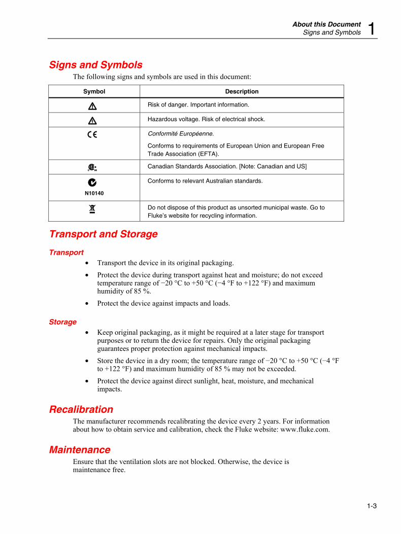
Signs and Symbols The following signs and symbols are used in this document:
Symbol Description
W Risk of danger. Important information.
X Hazardous voltage. Risk of electrical shock.
P Conformité Européenne.
Conforms to requirements of European Union and European Free Trade Association (EFTA).
) Canadian Standards Association. [Note: Canadian and US]
; N10140
Conforms to relevant Australian standards.
~ Do not dispose of this product as unsorted municipal waste. Go to Fluke’s website for recycling information.
Transport and Storage
Transport • Transport the device in its original packaging. • Protect the device during transport against heat and moisture; do not exceed
temperature range of −20 °C to +50 °C (−4 °F to +122 °F) and maximum humidity of 85 %.
• Protect the device against impacts and loads.
Storage • Keep original packaging, as it might be required at a later stage for transport
purposes or to return the device for repairs. Only the original packaging guarantees proper protection against mechanical impacts.
• Store the device in a dry room; the temperature range of −20 °C to +50 °C (−4 °F to +122 °F) and maximum humidity of 85 % may not be exceeded.
• Protect the device against direct sunlight, heat, moisture, and mechanical impacts.
Recalibration The manufacturer recommends recalibrating the device every 2 years. For information about how to obtain service and calibration, check the Fluke website: www.fluke.com.
Maintenance Ensure that the ventilation slots are not blocked. Otherwise, the device is maintenance free.
NORMA 4000/5000 Operators Manual
1-4
Decommissioning and Disposal
Shutting Down • Ensure that all connected devices are switched off and disconnected from the
power supply. • Switch off the Power Analyzer. • Disconnect the plug from the mains (power) socket. • Remove all connected devices. • Secure the unit against inadvertent switching on. • Keep the Operators Manual near the device.
Recycling and Disposal Always adhere to the applicable statutory regulations for recycling and waste disposal.
Housing The housing is made of metal and can be recycled.
Electronic Components The electronic components including the power adapter, filter, plug-in modules, and wires have a weight of approximately 1500 g (3.3 lb) and a volume of approximately 3000 cm3 (183 in3).
2-1
Chapter 2 General Safety Instructions
Title Page
Introduction........................................................................................................ 2-3 Protection Class ................................................................................................. 2-3 Qualified Personnel............................................................................................ 2-3 Safe Operation ................................................................................................... 2-3 Proper Use.......................................................................................................... 2-3 Warranty ............................................................................................................ 2-3 Electrical Connections ....................................................................................... 2-4 Risks During Operation ..................................................................................... 2-4 Maintenance and Repairs................................................................................... 2-4 Accessories ........................................................................................................ 2-4 Shutting Down ................................................................................................... 2-4 Safety Instructions on the Device Housing........................................................ 2-5
Mains Connection.......................................................................................... 2-5 Input Voltage and Maintenance..................................................................... 2-5 Indoor Use Only ............................................................................................ 2-5

NORMA 4000/5000 Operators Manual
2-2
General Safety Instructions Introduction 2
2-3
Introduction The design and manufacture of this device conform to the latest state of technology and the safety standards defined in IEC 61010-1/ 2nd edition. If used improperly, there is a risk of damage to persons and property.
Protection Class The device is assigned to protection class I according to IEC 61010-1 and is equipped with a protective earth connector.
Qualified Personnel The device may be operated only by qualified personnel. This means only persons who are familiar with the installation, assembly, connection, inspection of connections, and operation of the analyzer and who have completed training in at least one of the following areas:
• Switching on/off, enabling, earth-grounding and identification of electrical circuits and devices/systems according to the applicable safety standards.
• Maintenance and operation of appropriate safety gear, in accordance with the applicable safety standards.
• First aid.
Safe Operation • Ensure that all persons using the device have read and fully understood the
Operators Manual and safety instructions. • The device may only be used under certain ambient conditions. Ensure that the
actual ambient conditions conform to the admissible conditions laid down in the chapter "Technical Data".
• During operation, ensure that the cooling vents are not obstructed. • Always comply with the instructions in Chapter 1, "Transport and Storage".
Proper Use Do not use the device for any other purpose than the measuring of voltages and currents that are within the measuring ranges and categories, including voltage to earth ground, detailed in the "Technical Data" chapter. Improper use shall void all warranty.
Warranty • The warranty period for fault-free operation is limited to 2 years from the date of
purchase. • The warranty period for accuracy is 2 years.
NORMA 4000/5000 Operators Manual
2-4
Electrical Connections • Ensure that the power and connecting cables used with the device are in proper
working order. • Ensure that the protective earth ground connector of the power lead is connected
according to the instructions to the low-resistance unit earth ground cable. • Ensure that the power and connecting cables as well as all accessories used in
conjunction with the device are in proper working order and clean. • Install the device in such a way that its power cable is accessible at all times and
can easily be disconnected. • For connection work, work in teams of at least two persons. • Do not use the device, if the housing or an operating element is damaged.
Risks During Operation • Ensure that the connected devices work properly. • In the case of a direct connection to current circuits (without transformer or
shunt), ensure that the circuit is protected to maximum 16 A.
Maintenance and Repairs • Do not open the housing. Do not carry out any repairs and do not replace any
component parts of the device. • Damaged connecting and power leads must be repaired or replaced by an
authorized service technician. • Damaged or defective devices may only be repaired by authorized technicians.
Accessories • Only use the accessories supplied with the device or specifically available as
optional equipment for your model. • Ensure that any third-party accessories used in conjunction with the device
conform to the IEC 61010-2-031/-032 standard and are suitable for the respective measuring voltage range.
Shutting Down • If you detect any damage to the housing, controls, power cable, connecting leads,
or connected devices, immediately disconnect the unit from the power supply. • If you are in doubt as regards the safe operation of the device, immediately shut
down the unit and the respective accessories, secure them against inadvertent switching on, and bring them to an authorized service agent.
General Safety Instructions Safety Instructions on the Device Housing 2
2-5
Safety Instructions on the Device Housing
Mains Connection The mains connection must conform to the following ranges/values: 85 to 264 V AC at 47 to 440 Hz, or 120 to 370 V DC. Maximum power consumption is 65 VA.
Input Voltage and Maintenance
XW Warning The maximum input voltage for installation category CAT II may not exceed 1000 V to earth (J).
• Do not remove the cover.
• Refer servicing to qualified personnel.
Indoor Use Only The device may only be used indoors.
Conformity mark: EC Low Voltage Directive 73/23/EEC and EMC Directive 89/336/EEC.

NORMA 4000/5000 Operators Manual
2-6
3-1
Chapter 3 Design and Functions
Title Page
About this Chapter ............................................................................................. 3-3 Terminals (Back) ............................................................................................... 3-3 Operating Controls and Display......................................................................... 3-4
Navigation and Measuring Keys ................................................................... 3-5 Navigation through Display .......................................................................... 3-6 Overview of Function Keys........................................................................... 3-6
Functions............................................................................................................ 3-7

NORMA 4000/5000 Operators Manual
3-2
Design and Functions About this Chapter 3
3-3
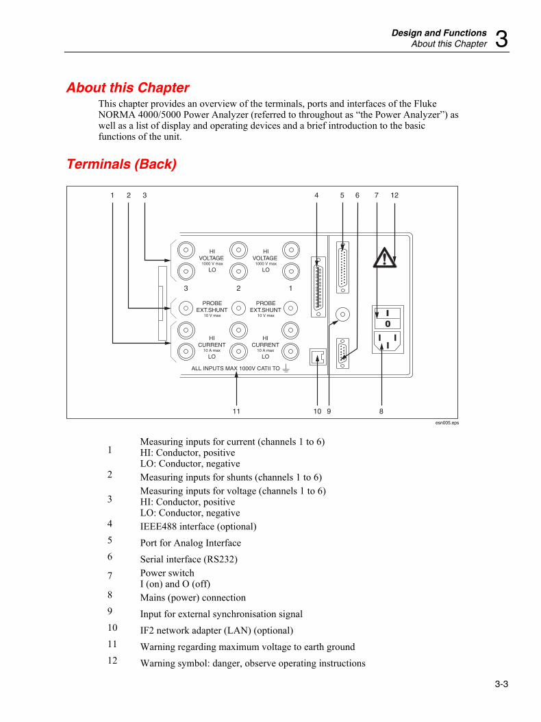
About this Chapter This chapter provides an overview of the terminals, ports and interfaces of the Fluke NORMA 4000/5000 Power Analyzer (referred to throughout as “the Power Analyzer”) as well as a list of display and operating devices and a brief introduction to the basic functions of the unit.
Terminals (Back)
HIVOLTAGE
1000 V max
LO
PROBEEXT.SHUNT
10 V max
1
1 2 3 4
891011
5 6 7 12
23
HICURRENT
10 A max
LO
ALL INPUTS MAX 1000V CATII TO
PROBEEXT.SHUNT
10 V max
HICURRENT
10 A max
LO
HIVOLTAGE
1000 V max
LO
esn005.eps
1 Measuring inputs for current (channels 1 to 6) HI: Conductor, positive LO: Conductor, negative
2 Measuring inputs for shunts (channels 1 to 6)
3 Measuring inputs for voltage (channels 1 to 6) HI: Conductor, positive LO: Conductor, negative
4 IEEE488 interface (optional) 5 Port for Analog Interface 6 Serial interface (RS232) 7 Power switch
I (on) and O (off) 8 Mains (power) connection 9 Input for external synchronisation signal 10 IF2 network adapter (LAN) (optional) 11 Warning regarding maximum voltage to earth ground 12 Warning symbol: danger, observe operating instructions
NORMA 4000/5000 Operators Manual
3-4
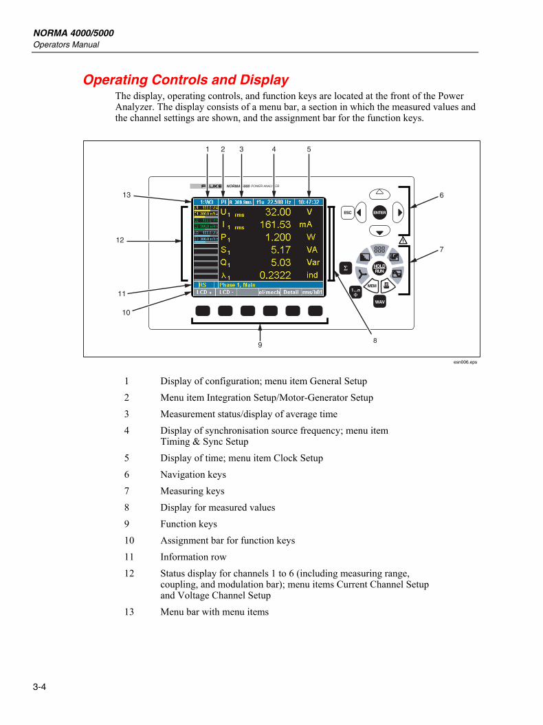
Operating Controls and Display The display, operating controls, and function keys are located at the front of the Power Analyzer. The display consists of a menu bar, a section in which the measured values and the channel settings are shown, and the assignment bar for the function keys.
MEM
POWER ANALYZERNORMA 5000
ENTERESC
1...n
WAV
HOLDRUN
1
9
10
11
12
13
2 3 4 5
6
7
8
esn006.eps
1 Display of configuration; menu item General Setup 2 Menu item Integration Setup/Motor-Generator Setup 3 Measurement status/display of average time 4 Display of synchronisation source frequency; menu item
Timing & Sync Setup 5 Display of time; menu item Clock Setup 6 Navigation keys 7 Measuring keys 8 Display for measured values 9 Function keys 10 Assignment bar for function keys 11 Information row 12 Status display for channels 1 to 6 (including measuring range,
coupling, and modulation bar); menu items Current Channel Setup and Voltage Channel Setup
13 Menu bar with menu items
Design and Functions Operating Controls and Display 3
3-5
Explanation of Status Symbols
Status Description
M Memory record active
T Wait for Trigger start condition (memory)
R Measurement active (Run mode)
H Measurement stopped (Hold mode)
∫ Integration of selected values active
Navigation and Measuring Keys
MEM
ENTERESC
1...n
WAV
HOLDRUN
26 27
14
19
15
17
27
16
18
2021
22
23
24
25
esn007.eps
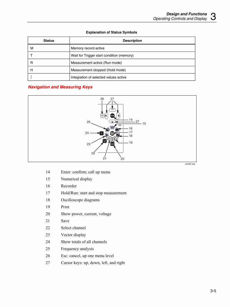
14 Enter: confirm; call up menu 15 Numerical display 16 Recorder 17 Hold/Run: start and stop measurement 18 Oscilloscope diagrams 19 Print 20 Show power, current, voltage 21 Save 22 Select channel 23 Vector display 24 Show totals of all channels 25 Frequency analysis 26 Esc: cancel, up one menu level 27 Cursor keys: up, down, left, and right
NORMA 4000/5000 Operators Manual
3-6
Navigation through Display 1. Use the navigation keys (6) and (27) to navigate through the display and the
menus. The active menu item, display, or entry field in which your cursor is located is backlit.
2. Press Esc (26) to cancel an entry without saving or to go to the next higher menu level.
3. Press Enter (14) to call up a menu or to confirm an entry made in a menu. 4. Press the measuring keys (7) and (15) to (25) to select the display mode and the
save or output functions for measured values. The assignment of the function keys (9) varies, depending on the current menu. The current key assignment is shown on the assignment bar (10) located above the function keys.
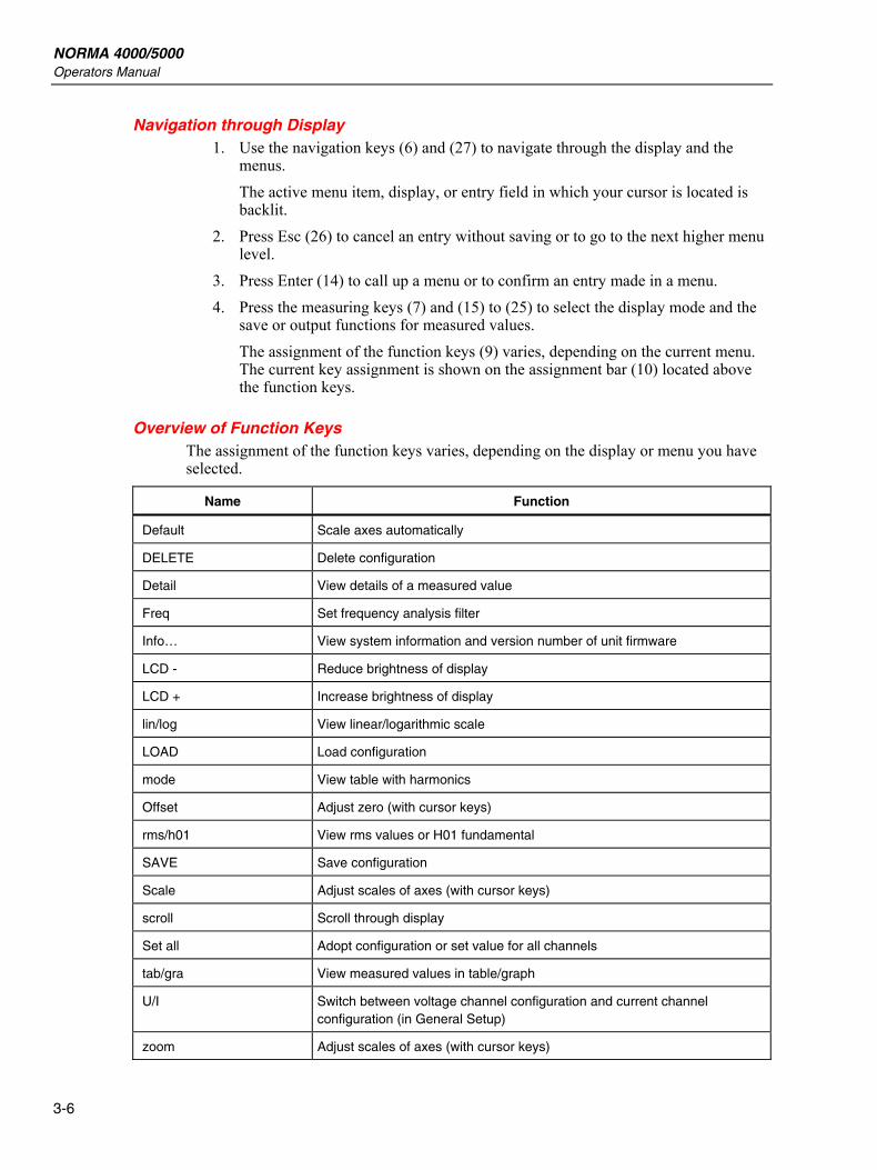
Overview of Function Keys The assignment of the function keys varies, depending on the display or menu you have selected.
Name Function
Default Scale axes automatically
DELETE Delete configuration
Detail View details of a measured value
Freq Set frequency analysis filter
Info… View system information and version number of unit firmware
LCD - Reduce brightness of display
LCD + Increase brightness of display
lin/log View linear/logarithmic scale
LOAD Load configuration
mode View table with harmonics
Offset Adjust zero (with cursor keys)
rms/h01 View rms values or H01 fundamental
SAVE Save configuration
Scale Adjust scales of axes (with cursor keys)
scroll Scroll through display
Set all Adopt configuration or set value for all channels
tab/gra View measured values in table/graph
U/I Switch between voltage channel configuration and current channel configuration (in General Setup)
zoom Adjust scales of axes (with cursor keys)
Design and Functions Functions 3
3-7
Name Function
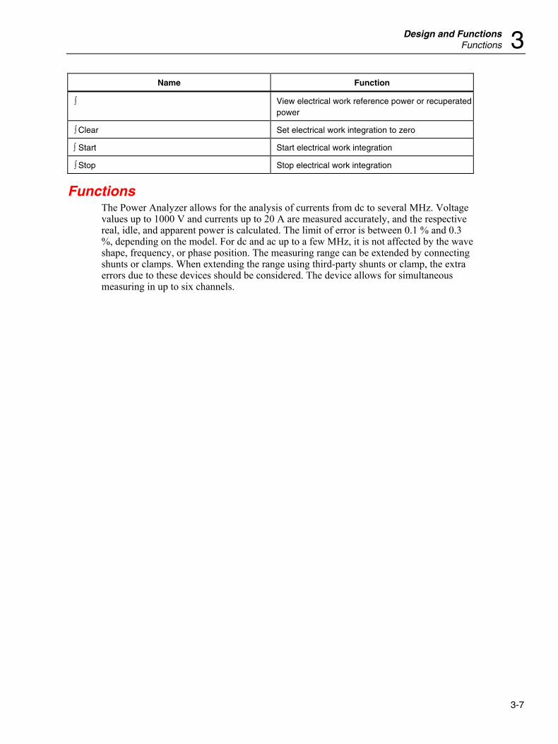
∫ View electrical work reference power or recuperated power
∫ Clear Set electrical work integration to zero
∫ Start Start electrical work integration
∫ Stop Stop electrical work integration
Functions The Power Analyzer allows for the analysis of currents from dc to several MHz. Voltage values up to 1000 V and currents up to 20 A are measured accurately, and the respective real, idle, and apparent power is calculated. The limit of error is between 0.1 % and 0.3 %, depending on the model. For dc and ac up to a few MHz, it is not affected by the wave shape, frequency, or phase position. The measuring range can be extended by connecting shunts or clamps. When extending the range using third-party shunts or clamp, the extra errors due to these devices should be considered. The device allows for simultaneous measuring in up to six channels.

NORMA 4000/5000 Operators Manual
3-8
4-1
Chapter 4 Startup
Title Page
Taking Inventory................................................................................................ 4-3 Installation and Switching On............................................................................ 4-3
Installation ..................................................................................................... 4-3 Switching Device On..................................................................................... 4-3 Switching Device Off .................................................................................... 4-4

NORMA 4000/5000 Operators Manual
4-2
Startup Taking Inventory 4
4-3
Taking Inventory Before you work with the analyzer, check the delivery to ensure that it is compete, using the following list and the delivery specifications:
• 1 Power Analyzer • 1 Operators Manual • 1 mains (power) cable • 1 calibration certificate • 1 built-in printer (if ordered) • 1 to 6 voltage and current channel modules, according to the delivery
specifications
Installation and Switching On
Installation
XW Warning Risk of electrocution. The device is connected to the power mains, with a number of internal components live with dangerous voltage levels. To ensure safe operation, the device must be equipped with a low-resistance connection to earth ground. Carefully check the mains socket and its wiring.
1. Follow the safety instructions regarding ambient conditions and location of installation.
2. Place the device on a clean and stable surface. 3. If necessary adjust the feet at the base of the unit to improve the view of the
display.
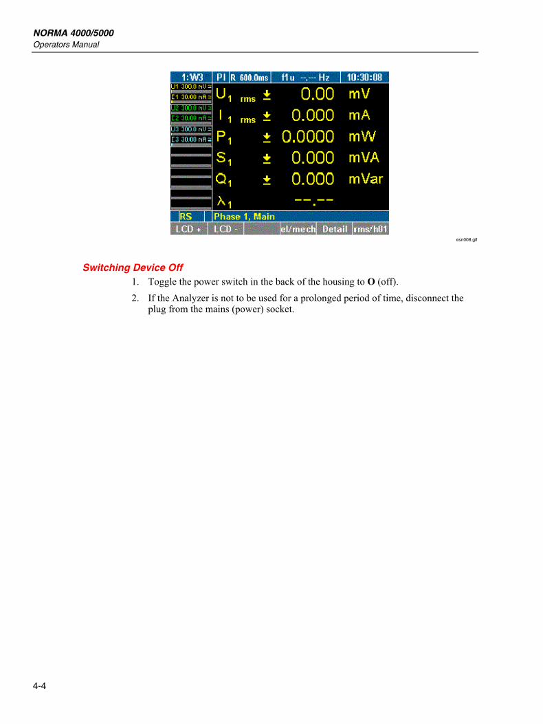
Switching Device On 1. Connect the Analyzer to the power (mains) socket, using the power cable. 2. Set the power switch on the back of the housing to I (on). The Analyzer is now
ready for operation. The following start screen displays.
NORMA 4000/5000 Operators Manual
4-4
esn008.gif
Switching Device Off 1. Toggle the power switch in the back of the housing to O (off). 2. If the Analyzer is not to be used for a prolonged period of time, disconnect the
plug from the mains (power) socket.
5-1
Chapter 5 Connection to Circuits
Title Page
Before You Begin .............................................................................................. 5-3 Connecting Sequence......................................................................................... 5-3 Overview............................................................................................................ 5-4 1-Phase Measurement ........................................................................................ 5-4
Direct Connection.......................................................................................... 5-4 Measurement with Shunt ............................................................................... 5-5 Measuring with Voltage and Current Transducer ......................................... 5-6
Aron Circuit (Triaxial/Guard Technique) .......................................................... 5-7 Direct Connection.......................................................................................... 5-7 Measuring with Shunt.................................................................................... 5-8 With Voltage and Current Transducer........................................................... 5-9
3-Phase Measurement in 4-Wire System........................................................... 5-10 Direct Connection.......................................................................................... 5-10 Measuring with Shunt.................................................................................... 5-11

NORMA 4000/5000 Operators Manual
5-2
Connection to Circuits Before You Begin 5
5-3
Before You Begin Carefully read and adhere to the following warning statements before you connect the Power Analyzer.
XW Warning • Risk of electrocution. By connecting the Power Analyzer
to active circuits, the terminals and certain parts inside the Power Analyzer are live.
• To ensure safe operation, first connect the Power Analyzer to the power supply.
• If possible, open the circuit before establishing a connection to the Power Analyzer.
• Prior to connecting the circuits, ensure that the maximum measuring voltage and maximum voltage to earth ground (1000 V CATII and 600 V CATIII respectively) are not exceeded.
• Do not use leads and accessories that do not fulfil the relevant safety standards, as this could lead to serious injury or death from electric shock. To avoid damage to the instrument, never apply voltage to the current shunt inputs (lower set of input jacks, blue).
Connecting Sequence For safety reasons, when connecting a circuit to the Power Analyzer, proceed in the sequence outlined as follows:
1. Connect the Power Analyzer to the mains (power) socket. The Power Analyzer is now connected to the protective earth ground wire.
2. Switch on the Power Analyzer. 3. Connect the measuring circuit as shown in the connection diagrams later in this
Operators Manual. To ensure that the measured values are indicated correctly, connect the phase to HI so that the energy flow is from HI to LO.
4. Connect the circuit to the power supply.
NORMA 4000/5000 Operators Manual
5-4
Overview The Fluke NORMA 4000/5000 Power Analyzer offers the following options for connection:
• 1-phase measurement • Aron connection • 3-phase measurement in 4-wire system
Note When connecting a 4-channel device for electrical efficiency analysis, the 3-phase power cables for this measurement should be connected to the measuring channels 1 to 3, so that the efficiency can be calculated and displayed directly on the Power Analyzer.
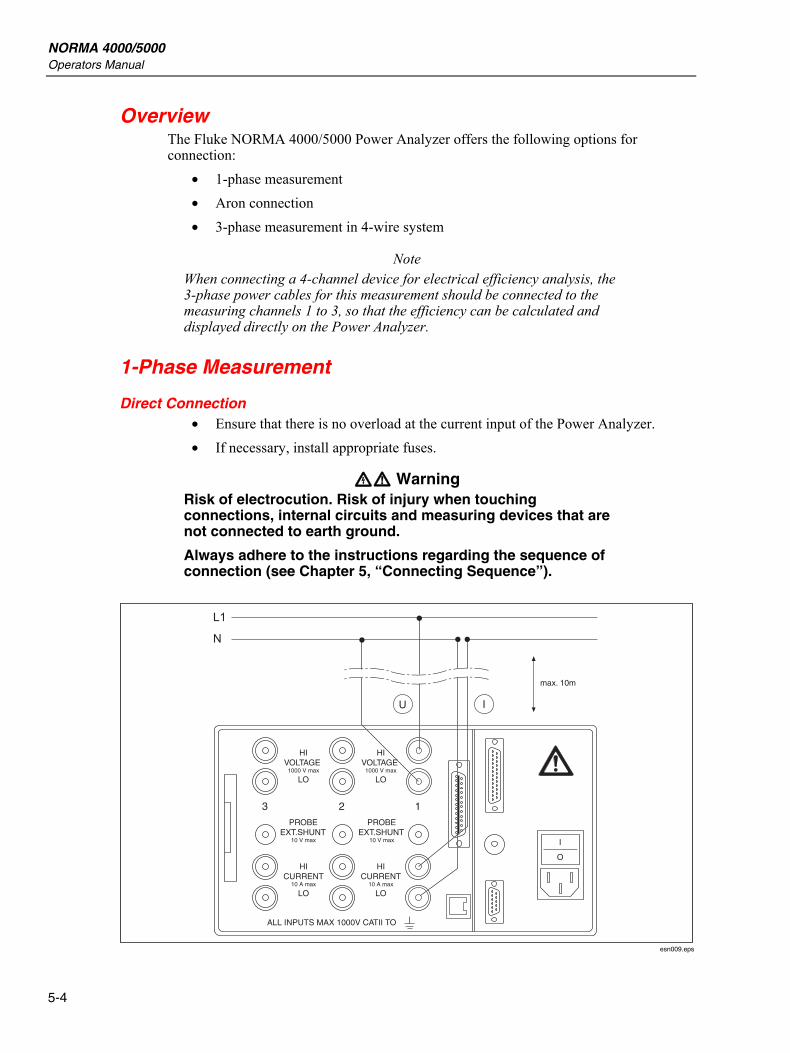
1-Phase Measurement
Direct Connection • Ensure that there is no overload at the current input of the Power Analyzer. • If necessary, install appropriate fuses.
XW Warning Risk of electrocution. Risk of injury when touching connections, internal circuits and measuring devices that are not connected to earth ground.
Always adhere to the instructions regarding the sequence of connection (see Chapter 5, “Connecting Sequence”).
HIVOLTAGE
1000 V max
LO
PROBEEXT.SHUNT
10 V max
ALL INPUTS MAX 1000V CATII TO
I
O
PROBEEXT.SHUNT
10 V max
HICURRENT
10 A max
LO
HICURRENT
10 A max
LO
HIVOLTAGE
1000 V max
LO
max. 10m
123
esn009.eps
Connection to Circuits 1-Phase Measurement 5
5-5
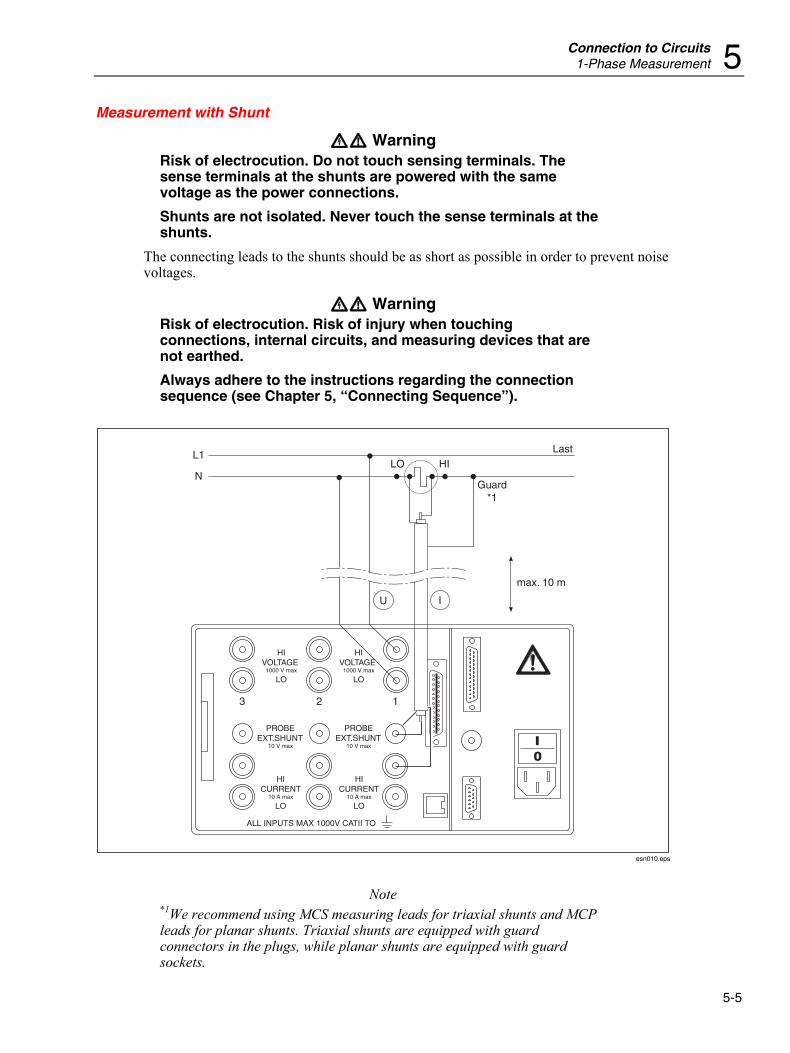
Measurement with Shunt
XW Warning Risk of electrocution. Do not touch sensing terminals. The sense terminals at the shunts are powered with the same voltage as the power connections.
Shunts are not isolated. Never touch the sense terminals at the shunts.
The connecting leads to the shunts should be as short as possible in order to prevent noise voltages.
XW Warning Risk of electrocution. Risk of injury when touching connections, internal circuits, and measuring devices that are not earthed.
Always adhere to the instructions regarding the connection sequence (see Chapter 5, “Connecting Sequence”).
HIVOLTAGE
1000 V max
LO
PROBEEXT.SHUNT
10 V max
HICURRENT
10 A max
LO
ALL INPUTS MAX 1000V CATII TO
PROBEEXT.SHUNT
10 V max
HICURRENT
10 A max
LO
HIVOLTAGE
1000 V max
LO
max. 10 m
LastHILO
L1
NGuard
*1
123
esn010.eps
Note *1We recommend using MCS measuring leads for triaxial shunts and MCP leads for planar shunts. Triaxial shunts are equipped with guard connectors in the plugs, while planar shunts are equipped with guard sockets.
NORMA 4000/5000 Operators Manual
5-6
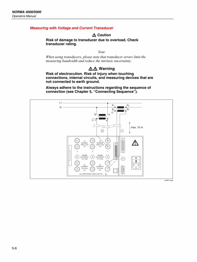
Measuring with Voltage and Current Transducer
W Caution Risk of damage to transducer due to overload. Check transducer rating.
Note When using transducers, please note that transducer errors limit the measuring bandwidth and reduce the intrinsic uncertainty.
XW Warning Risk of electrocution. Risk of injury when touching connections, internal circuits, and measuring devices that are not connected to earth ground.
Always adhere to the instructions regarding the sequence of connection (see Chapter 5, “Connecting Sequence”).
HIVOLTAGE
1000 V maxLO
PROBEEXT.SHUNT
10 V max
123
HICURRENT10 A max
LO
ALL INPUTS MAX 1000V CATII TO
PROBEEXT.SHUNT
10 V max
HICURRENT10 A max
LO
HIVOLTAGE
1000 V maxLO
max. 10 m
S1
A
an
N
N
L1
S2
P1 P2
esn011.eps
Connection to Circuits Aron Circuit (Triaxial/Guard Technique) 5
5-7
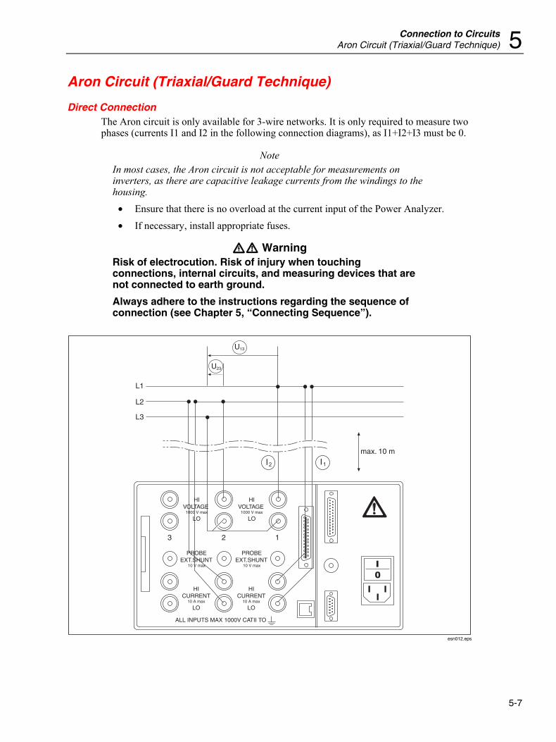
Aron Circuit (Triaxial/Guard Technique)
Direct Connection The Aron circuit is only available for 3-wire networks. It is only required to measure two phases (currents I1 and I2 in the following connection diagrams), as I1+I2+I3 must be 0.
Note In most cases, the Aron circuit is not acceptable for measurements on inverters, as there are capacitive leakage currents from the windings to the housing.
• Ensure that there is no overload at the current input of the Power Analyzer. • If necessary, install appropriate fuses.
XW Warning Risk of electrocution. Risk of injury when touching connections, internal circuits, and measuring devices that are not connected to earth ground.
Always adhere to the instructions regarding the sequence of connection (see Chapter 5, “Connecting Sequence”).
HIVOLTAGE
1000 V max
LO
PROBEEXT.SHUNT
10 V max
123
HICURRENT
10 A max
LO
ALL INPUTS MAX 1000V CATII TO
PROBEEXT.SHUNT
10 V max
HICURRENT
10 A max
LO
HIVOLTAGE
1000 V max
LO
max. 10 m
U
L1
L2
L3
23
U13
esn012.eps
NORMA 4000/5000 Operators Manual
5-8
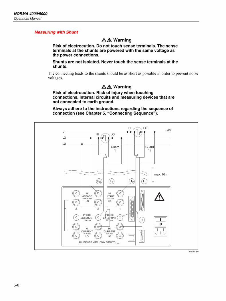
Measuring with Shunt
XW Warning Risk of electrocution. Do not touch sense terminals. The sense terminals at the shunts are powered with the same voltage as the power connections.
Shunts are not isolated. Never touch the sense terminals at the shunts.
The connecting leads to the shunts should be as short as possible in order to prevent noise voltages.
XW Warning Risk of electrocution. Risk of injury when touching connections, internal circuits and measuring devices that are not connected to earth ground.
Always adhere to the instructions regarding the sequence of connection (see Chapter 5, “Connecting Sequence”).
HIVOLTAGE
1000 V max
LO
PROBEEXT.SHUNT
10 V max
123
HICURRENT
10 A max
LO
ALL INPUTS MAX 1000V CATII TO
PROBEEXT.SHUNT
10 V max
HICURRENT
10 A max
LO
HIVOLTAGE
1000 V max
LO
max. 10 m
LastLO
Guard*1
Guard*1
HI
LOHIL1
L2
L3
esn013.eps
Connection to Circuits Aron Circuit (Triaxial/Guard Technique) 5
5-9
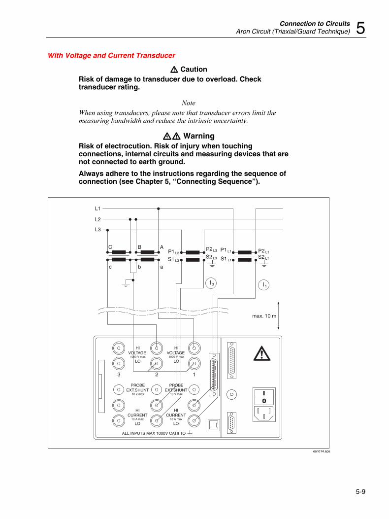
With Voltage and Current Transducer
W Caution Risk of damage to transducer due to overload. Check transducer rating.
Note When using transducers, please note that transducer errors limit the measuring bandwidth and reduce the intrinsic uncertainty.
XW Warning Risk of electrocution. Risk of injury when touching connections, internal circuits and measuring devices that are not connected to earth ground.
Always adhere to the instructions regarding the sequence of connection (see Chapter 5, “Connecting Sequence”).
HIVOLTAGE
1000 V max
LO
PROBEEXT.SHUNT
10 V max
12
max. 10 m
S1 L1
P1 L1
S2 L3
P2 L3
S1
A
a
B
b
C
L1
L2
L3
cL3
P1 L3S2 L1
P2 L1
3
HICURRENT
10 A max
LO
ALL INPUTS MAX 1000V CATII TO
PROBEEXT.SHUNT
10 V max
HICURRENT
10 A max
LO
HIVOLTAGE
1000 V max
LO
esn014.eps
NORMA 4000/5000 Operators Manual
5-10
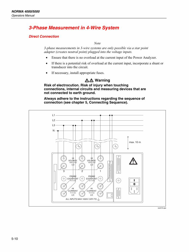
3-Phase Measurement in 4-Wire System
Direct Connection
Note 3-phase measurements in 3-wire systems are only possible via a star point adapter (creates neutral point) plugged into the voltage inputs.
• Ensure that there is no overload at the current input of the Power Analyzer. • If there is a potential risk of overload at the current input, incorporate a shunt or
transducer into the circuit. • If necessary, install appropriate fuses.
XW Warning Risk of electrocution. Risk of injury when touching connections, internal circuits and measuring devices that are not connected to earth ground.
Always adhere to the instructions regarding the sequence of connection (see chapter 5, Connecting Sequence).
HIVOLTAGE
1000 V max
LO
PROBEEXT.SHUNT
10 V max
123
L1
L2
L3
N
HICURRENT
10 A max
LO
ALL INPUTS MAX 1000V CATII TO
PROBEEXT.SHUNT
10 V max
HICURRENT
10 A max
LO
HIVOLTAGE
1000 V max
LO
max. 10 m
esn015.eps
Connection to Circuits 3-Phase Measurement in 4-Wire System 5
5-11
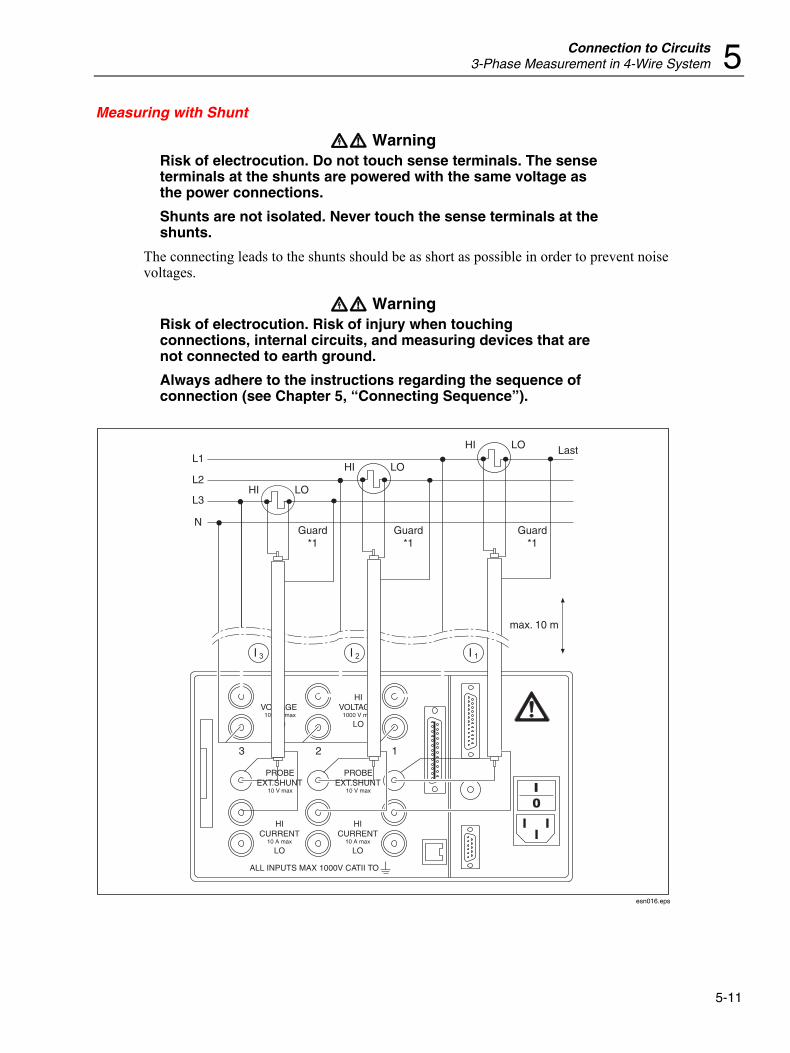
Measuring with Shunt
XW Warning Risk of electrocution. Do not touch sense terminals. The sense terminals at the shunts are powered with the same voltage as the power connections.
Shunts are not isolated. Never touch the sense terminals at the shunts.
The connecting leads to the shunts should be as short as possible in order to prevent noise voltages.
XW Warning Risk of electrocution. Risk of injury when touching connections, internal circuits, and measuring devices that are not connected to earth ground.
Always adhere to the instructions regarding the sequence of connection (see Chapter 5, “Connecting Sequence”).
HIVOLTAGE
1000 V max
LO
PROBEEXT.SHUNT
10 V max
123
HICURRENT
10 A max
LO
ALL INPUTS MAX 1000V CATII TO
PROBEEXT.SHUNT
10 V max
HICURRENT
10 A max
LO
HIVOLTAGE
1000 V max
LO
max. 10 m
Guard*1
Guard*1
Guard*1
LastHI LO
HI LO
HI
L1
L2
L3
N
LO
esn016.eps

NORMA 4000/5000 Operators Manual
5-12
6-1
Chapter 6 Simple Measurement
Title Page
About this Chapter ............................................................................................. 6-3 Connection to Circuits ....................................................................................... 6-3 Configuration ..................................................................................................... 6-3 Measuring .......................................................................................................... 6-3

NORMA 4000/5000 Operators Manual
6-2
Simple Measurement About this Chapter 6
6-3
About this Chapter This chapter contains an introduction to the measuring procedures that can be carried out with the Power Analyzer, based on a sample measurement. The example used here is a measurement at the frequency converter with a fundamental below 100 Hz.
Connection to Circuits Connect the outputs of the frequency converter to the current and voltage channels of the Power Analyzer (see the section “3-Phase Measurement in 4-Wire System” in Chapter 5, “Direct Connection”).
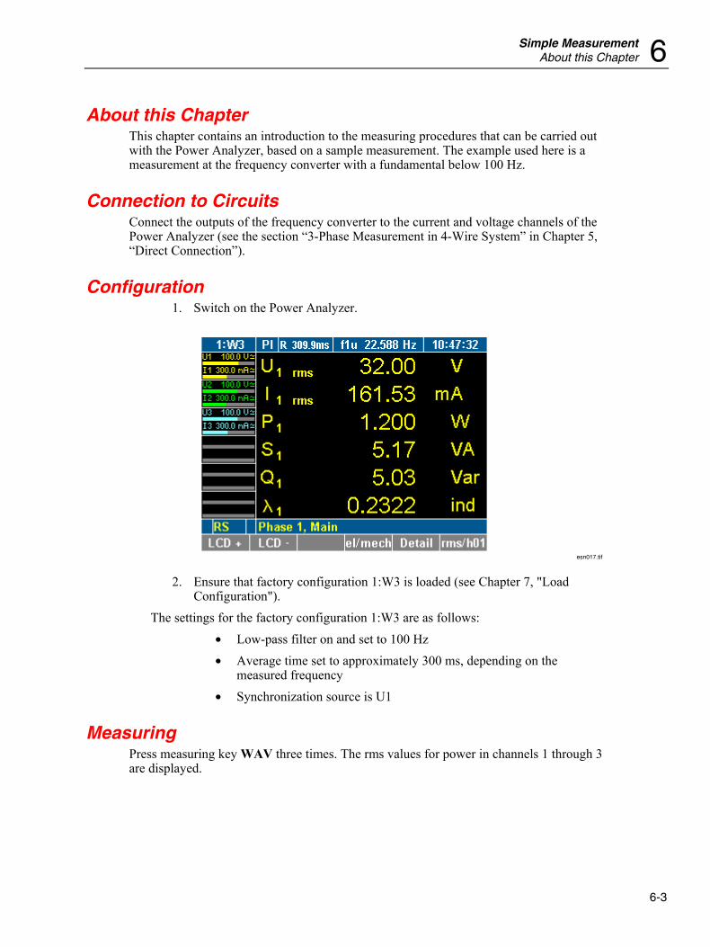
Configuration 1. Switch on the Power Analyzer.
esn017.tif
2. Ensure that factory configuration 1:W3 is loaded (see Chapter 7, "Load Configuration").
The settings for the factory configuration 1:W3 are as follows: • Low-pass filter on and set to 100 Hz • Average time set to approximately 300 ms, depending on the
measured frequency • Synchronization source is U1
Measuring Press measuring key WAV three times. The rms values for power in channels 1 through 3 are displayed.
NORMA 4000/5000 Operators Manual
6-4
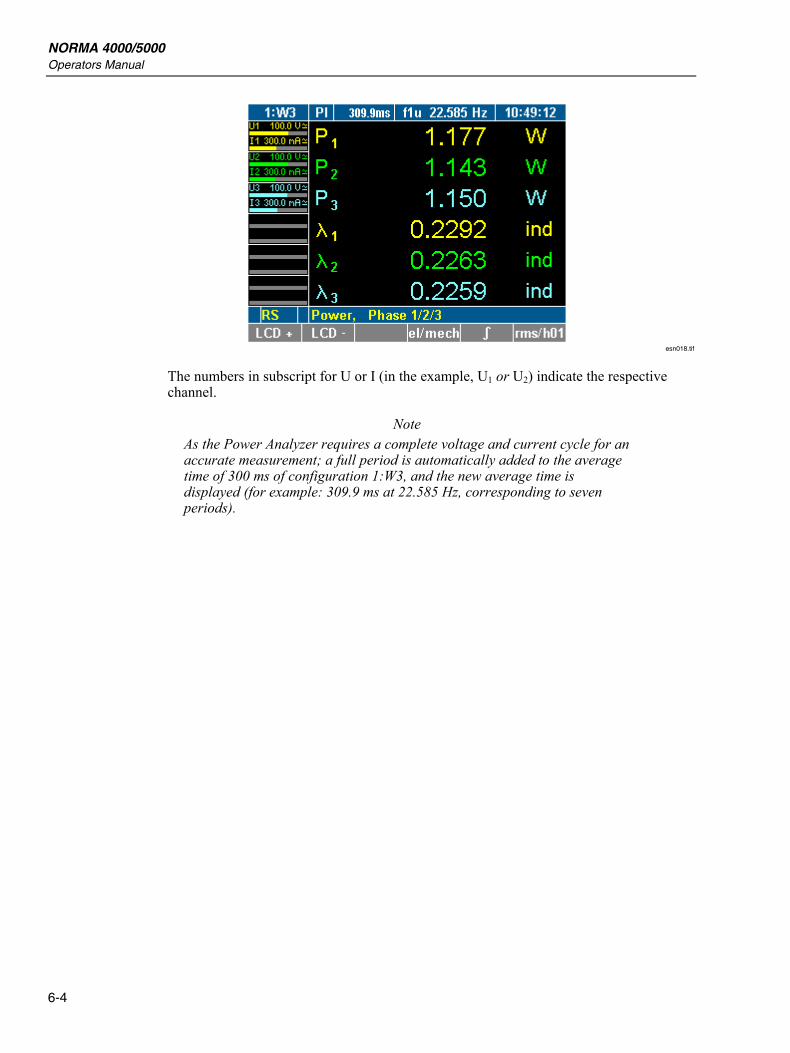
esn018.tif
The numbers in subscript for U or I (in the example, U1 or U2) indicate the respective channel.
Note As the Power Analyzer requires a complete voltage and current cycle for an accurate measurement; a full period is automatically added to the average time of 300 ms of configuration 1:W3, and the new average time is displayed (for example: 309.9 ms at 22.585 Hz, corresponding to seven periods).
7-1
Chapter 7 Configuration
Title Page
Set Up for Measuring......................................................................................... 7-3 Configuration 1:W3 ........................................................................................... 7-3 Five Steps........................................................................................................... 7-4 Call up General Setup and System Information Screen..................................... 7-4
General Setup ................................................................................................ 7-4 System Information Screen ........................................................................... 7-4
Load Configuration............................................................................................ 7-5 Load Configuration (Optional)...................................................................... 7-5 Modify Loaded Configurations ..................................................................... 7-5
Configure Data Transfer to Printer and PC........................................................ 7-5 Configure External Printer ............................................................................ 7-6 Configure Interface to PC.............................................................................. 7-7 Configure RS 232 .......................................................................................... 7-7 Configure GPIB Address............................................................................... 7-8 Configure Ethernet ........................................................................................ 7-8
Configure Average Time and Synchronization ................................................. 7-9 Timing & Sync Setup .................................................................................... 7-9 Set Average Time .......................................................................................... 7-10 Select Synchronization Source ...................................................................... 7-11 Set Trigger Level ........................................................................................... 7-11 Select Slope Direction ................................................................................... 7-12 Select Low-Pass Filter ................................................................................... 7-12 Configure Signal Output................................................................................ 7-12
Adjust Date and Time ........................................................................................ 7-13 Configure Current and Voltage Channels.......................................................... 7-13
Current Channel Setup .................................................................................. 7-14 Configure Input Range .................................................................................. 7-15
Automatic Range Adjustment (Auto) ....................................................... 7-15 Manual Range Adjustment (Range).......................................................... 7-15
Configure Scale ............................................................................................. 7-15 Configure Coupling ....................................................................................... 7-16 Configure Filter ............................................................................................. 7-17 Voltage Channel Setup .................................................................................. 7-17
Switch Current Input to External Input (BNC).................................................. 7-18 Switch Current Input ..................................................................................... 7-18
NORMA 4000/5000 Operators Manual
7-2
Configure Auto-Range Selection................................................................... 7-18 Configure Scale ............................................................................................. 7-18
Integration Function Configuration ................................................................... 7-19 Integration Setup ........................................................................................... 7-19 Select Integration Value ................................................................................ 7-21 Configure Status ............................................................................................ 7-21 Configure Start .............................................................................................. 7-22 Configure Stop............................................................................................... 7-23
Save Configuration ............................................................................................ 7-23 Delete Configuration.......................................................................................... 7-24 Undersampling and Aliasing.............................................................................. 7-24
Configuration Set Up for Measuring 7
7-3
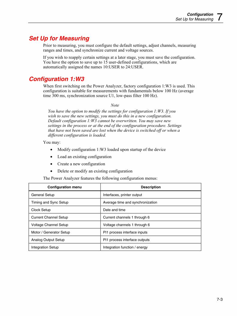
Set Up for Measuring Prior to measuring, you must configure the default settings, adjust channels, measuring ranges and times, and synchronize current and voltage sources. If you wish to reapply certain settings at a later stage, you must save the configuration. You have the option to save up to 15 user-defined configurations, which are automatically assigned the names 10:USER to 24:USER.
Configuration 1:W3 When first switching on the Power Analyzer, factory configuration 1:W3 is used. This configuration is suitable for measurements with fundamentals below 100 Hz (average time 300 ms, synchronization source U1, low-pass filter 100 Hz).
Note You have the option to modify the settings for configuration 1:W3. If you wish to save the new settings, you must do this in a new configuration. Default configuration 1:W3 cannot be overwritten. You may save new settings in the process or at the end of the configuration procedure. Settings that have not been saved are lost when the device is switched off or when a different configuration is loaded.
You may: • Modify configuration 1:W3 loaded upon startup of the device • Load an existing configuration • Create a new configuration • Delete or modify an existing configuration
The Power Analyzer features the following configuration menus:
Configuration menu Description
General Setup Interfaces, printer output
Timing and Sync Setup Average time and synchronization
Clock Setup Date and time
Current Channel Setup Current channels 1 through 6
Voltage Channel Setup Voltage channels 1 through 6
Motor / Generator Setup PI1 process interface inputs
Analog Output Setup PI1 process interface outputs
Integration Setup Integration function / energy
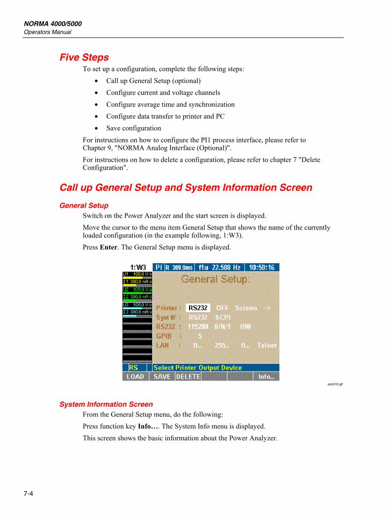
NORMA 4000/5000 Operators Manual
7-4
Five Steps To set up a configuration, complete the following steps:
• Call up General Setup (optional) • Configure current and voltage channels • Configure average time and synchronization • Configure data transfer to printer and PC • Save configuration
For instructions on how to configure the PI1 process interface, please refer to Chapter 9, "NORMA Analog Interface (Optional)". For instructions on how to delete a configuration, please refer to chapter 7 "Delete Configuration".
Call up General Setup and System Information Screen
General Setup Switch on the Power Analyzer and the start screen is displayed. Move the cursor to the menu item General Setup that shows the name of the currently loaded configuration (in the example following, 1:W3). Press Enter. The General Setup menu is displayed.
esn019.gif
System Information Screen From the General Setup menu, do the following: Press function key Info…. The System Info menu is displayed. This screen shows the basic information about the Power Analyzer.
Configuration Load Configuration 7
7-5
Line Description
System Device type and sample rate
Phases Type and number of equipped power phases
Options Equipped interfaces and options
Serial Serial number
Version Firmware version
Load Configuration Note
If you have not set up and saved a new configuration before, you are currently working with factory configuration 1:W3.
Load Configuration (Optional) 1. Proceed as described in Chapter 7, "Configure Data Transfer to Printer and PC". 2. Press function key LOAD.
A list showing all existing configurations is displayed. 3. Select a configuration and confirm by pressing Enter.
The name of the loaded configuration, for example, 10:USER, is displayed in menu item General Setup.
Modify Loaded Configurations To modify the loaded configuration, proceed as described in the following sections.
Configure Data Transfer to Printer and PC If you wish to use an internal or external printer, or if you intend to connect a PC, you must configure the parameters for the data exchange. This procedure consists of the following steps:
• Configure external printer • Configure interface to PC • Configure RS232 • Configure IEEE488 device address • Configure network (LAN) addresses
Note The actual selected interface is displayed in the Information row (see Chapter 3, “Operating Controls and Display”):
RS → RS232, GP → IEEE488, EN → Ethernet, US → USB
NORMA 4000/5000 Operators Manual
7-6
In the General Setup menu, define the following settings:
Line Function
Printer Configure printer
Syst IF Configure interface to PC
RS232 Configure RS232 interface
GPIB Configure IEEE488 device address
LAN Configure network (LAN) addresses
The device can be equipped with an IEEE488 and/or an Ethernet interface instead of a serial RS232 interface.
Configure External Printer
Settings Description
RS232 intern
Print via RS232 interface on external printer or use internal printer
On key Off
Printer activated Printer deactivated
Screen Num
Print screenshot Print numerical data
1/page 3/page
Print 1 screenshot per page Print 3 screenshots per page
PCL EPS 9p EPS 24p
PCL printer Epson 9-pin printer Epson 24-pin printer
S/W Printing color is black/white
Note The PCL setting is suitable for most inkjet printers.
1. Move the cursor to the field with the value you wish to change, enter the new value and confirm by pressing Enter.
2. Select the settings and confirm by pressing Enter. The applied settings are shown in line Printer.
Configuration Configure Data Transfer to Printer and PC 7
7-7
Configure Interface to PC
Settings Description
RS232 Serial interface
GPIB General Purpose Interface Bus: IEEE488 interface (optional)
USB USB2.0 interface (optional)
LAN Ethernet (LAN) interface (optional)
SCPI Standard set of commands
D5255S Previous set of commands (emulation)
D5255T Previous set of commands (emulation)
D5255M Previous set of commands (emulation)
1. Move the cursor to the field with the value you wish to change, enter the new
value and confirm by pressing Enter. 2. Select the settings and confirm by pressing Enter.
The applied settings are shown in line Syst IF.
Note A CD to install USB driver support to the PC is included in the delivery content. The USB interface is installed as a virtual COM port.
Configure RS 232
Settings Description
115200 ...1200 Baud rate of serial interface
8/N/1 …7/O/1 Data bits/parity/stop bits of the serial interface
none
HW
XON
Handshake (protocol) of the serial interface
Note The factory settings of the RS232 interface are optimized for communication with a PC. We recommend adjusting the settings of the PC to suit these parameters.
Factory configuration: 115200 8/N/1 HW 1. At the connected PC, call up the Device Manager and open the dialog showing
the settings for the serial port. 2. Adjust these settings to those of the Power Analyzer.
NORMA 4000/5000 Operators Manual
7-8
Note If the cable connecting the two devices is extremely long, or if the PC is unable to handle data at the set rate, you might consider adjusting the RS232 settings for the Power Analyzer to those of the PC. To do this, proceed as follows:
1. Move the cursor to the first field in line RS232. 2. Enter the settings for baud rate, data bits/parity/stop bits and
handshake and confirm by pressing Enter. 3. The new settings are now shown in the fields of line RS232. 4. Save the configuration settings by pressing the SAVE function
key.
Configure GPIB Address The general-purpose interface bus (GPIB) port is an IEEE488 interface. The IEEE488 interface works like an IP address in a network. The Power Analyzer is assigned a unique device address (numerical code) for communication on the GPIB port. If more than one Power Analyzer is used simultaneously in the network, the device address can be adjusted accordingly.
1. Move the cursor to the field in line GPIB and press Enter. A list with available addresses is displayed.
2. Select an address that has not yet been assigned at the GPIB port and confirm with Enter. The selected address is shown in line GPIB.
Configure Ethernet
Settings Description
0..... Device IP address
0..... IP subnet mask address
0.... IP gateway address
Telnet Protocol (fixed)
Before the Ethernet interface can be operated properly, enter the correct network addresses.
1. Move the cursor to the field in line LAN and press Enter. A window with a numerical entry field is displayed.
2. Enter the required address and confirm by pressing Enter. The address is shown in line LAN.
3. Save the configuration settings by pressing the SAVE function key. Press Esc to leave the entry field without changing the address.
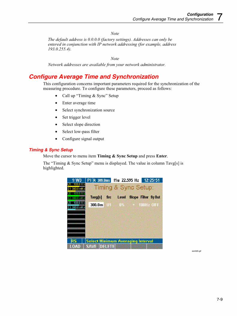
Configuration Configure Average Time and Synchronization 7
7-9
Note The default address is 0.0.0.0 (factory settings). Addresses can only be entered in conjunction with IP network addressing (for example, address 193.0.255.4).
Note Network addresses are available from your network administrator.
Configure Average Time and Synchronization This configuration concerns important parameters required for the synchronization of the measuring procedure. To configure these parameters, proceed as follows:
• Call up “Timing & Sync” Setup • Enter average time • Select synchronization source • Set trigger level • Select slope direction • Select low-pass filter • Configure signal output
Timing & Sync Setup Move the cursor to menu item Timing & Sync Setup and press Enter. The “Timing & Sync Setup” menu is displayed. The value in column Tavg[s] is highlighted.
esn020.gif
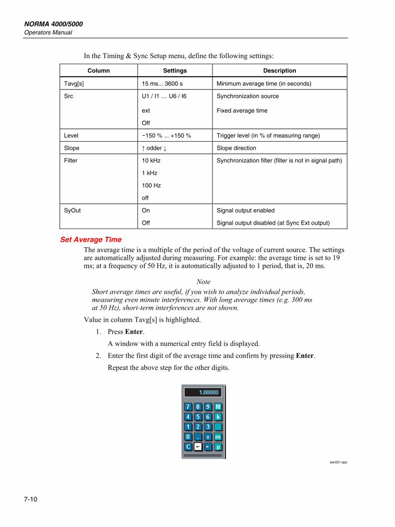
NORMA 4000/5000 Operators Manual
7-10
In the Timing & Sync Setup menu, define the following settings:
Column Settings Description
Tavg[s] 15 ms... 3600 s Minimum average time (in seconds)
U1 / I1 … U6 / I6 Synchronization source
ext Fixed average time
Src
Off
Level −150 % ... +150 % Trigger level (in % of measuring range)
Slope ↑ odder ↓ Slope direction
10 kHz Synchronization filter (filter is not in signal path)
1 kHz
100 Hz
Filter
off
On Signal output enabled SyOut
Off Signal output disabled (at Sync Ext output)
Set Average Time The average time is a multiple of the period of the voltage of current source. The settings are automatically adjusted during measuring. For example: the average time is set to 19 ms; at a frequency of 50 Hz, it is automatically adjusted to 1 period, that is, 20 ms.
Note Short average times are useful, if you wish to analyze individual periods, measuring even minute interferences. With long average times (e.g. 300 ms at 50 Hz), short-term interferences are not shown.
Value in column Tavg[s] is highlighted. 1. Press Enter.
A window with a numerical entry field is displayed. 2. Enter the first digit of the average time and confirm by pressing Enter.
Repeat the above step for the other digits.
esn021.eps
Configuration Configure Average Time and Synchronization 7
7-11
The measuring time is entered in seconds. For exponential powers, use the following keys on the numerical keypad:
Exponential Power Key
micro [10–6] μ
milli [10–3] m
kilo [103] k
mega [106] M
1. Enter the exponential power and confirm with Enter. 2. Move the cursor to the return field of the calculator and press Enter.
The average time is shown in column Tavg[s]. 3. Save the configuration settings by pressing the SAVE function key.
Select Synchronization Source The synchronization source determines the frequency on which the analysis is based. In factory configuration 1:W3, the synchronization source is U1, as this signal tends to be reliable in most cases. The following options are available:
• Input at device (channel 1 through 6), current or voltage respectively (U1 through U6, I1 through I6).
• Ext for external synchronization signal (connection to port for external synchronization signal).
• OFF, if no synchronization source is used (e.g. measuring of direct current).
Note To measure the start up of a machine, you might opt for an external synchronization signal (0.2 Hz to sample rate, max. 50 V), as there is otherwise no signal at the beginning of the measuring procedure, and thus no measured values.
Value in column Src is highlighted. 1. Press Enter. 2. Select a source or OFF and confirm by pressing Enter.
The selected source or OFF is shown in column Src. 3. Save the configuration settings by pressing the SAVE function key.
Set Trigger Level The trigger level is in percentages of the measuring range, and measured from the end value of the range. In factory configuration 1:W3, the trigger level is set to 0 %.
Note By increasing the trigger level, the level of the average is also increased. In other words: if there are several positive slopes in the zero crossing, a higher modulated signal can be triggered.
NORMA 4000/5000 Operators Manual
7-12
Value in column Level is highlighted. 1. Press Enter. 2. Enter the desired power and confirm by pressing Enter.
The value is displayed in column Level. 3. Save the configuration settings by pressing the SAVE function key.
Select Slope Direction The value entered here determines the zero crossing at which the measurement begins, that is, zero crossing with positive or with negative slope. In factory configuration 1:W3, a positive slope is set. The arrow symbol "↑" indicates to a positive slope; symbol "↓" indicates a negative slope. Highlight the value in column Slope.
1. Press Enter. 2. Select the desired arrow symbol and confirm by pressing Enter.
The selected arrow symbol is shown in column Slope. 3. Save the configuration settings by pressing the SAVE function key.
Select Low-Pass Filter The low-pass filter enables you to modify signals with high harmonic content (e.g. PWM) so that they are synchronized to the resulting fundamental. This ensures that all measured values refer to this fundamental. The low-pass filter is not located in the signal path so that the input signal is not in any way interfered with. Value in column Filter is highlighted.
1. Press Enter. 2. Select a value or OFF, depending on the expected fundamental, and confirm by
pressing Enter. The entered value, or OFF, is shown in column Filter.
3. Save the configuration settings by pressing the SAVE function key.
Configure Signal Output The value in column SyOut is highlighted.
1. Press Enter. 2. To activate output, select ON. 3. To deactivate output, select OFF. 4. Confirm by pressing Enter.
The entered value is shown in column SyOut. 5. Save the configuration settings by pressing the SAVE function key.
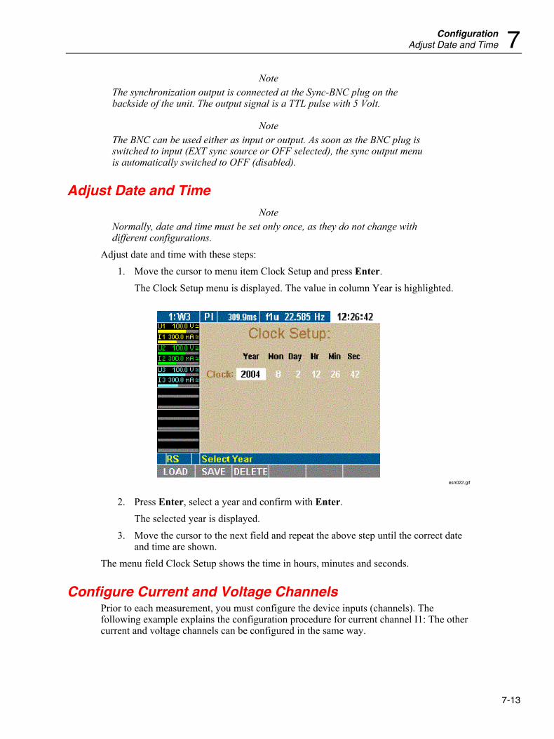
Configuration Adjust Date and Time 7
7-13
Note The synchronization output is connected at the Sync-BNC plug on the backside of the unit. The output signal is a TTL pulse with 5 Volt.
Note The BNC can be used either as input or output. As soon as the BNC plug is switched to input (EXT sync source or OFF selected), the sync output menu is automatically switched to OFF (disabled).
Adjust Date and Time Note
Normally, date and time must be set only once, as they do not change with different configurations.
Adjust date and time with these steps: 1. Move the cursor to menu item Clock Setup and press Enter.
The Clock Setup menu is displayed. The value in column Year is highlighted.
esn022.gif
2. Press Enter, select a year and confirm with Enter. The selected year is displayed.
3. Move the cursor to the next field and repeat the above step until the correct date and time are shown.
The menu field Clock Setup shows the time in hours, minutes and seconds.
Configure Current and Voltage Channels Prior to each measurement, you must configure the device inputs (channels). The following example explains the configuration procedure for current channel I1: The other current and voltage channels can be configured in the same way.
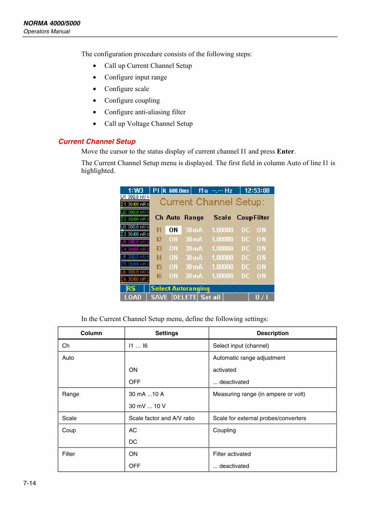
NORMA 4000/5000 Operators Manual
7-14
The configuration procedure consists of the following steps: • Call up Current Channel Setup • Configure input range • Configure scale • Configure coupling • Configure anti-aliasing filter • Call up Voltage Channel Setup
Current Channel Setup Move the cursor to the status display of current channel I1 and press Enter. The Current Channel Setup menu is displayed. The first field in column Auto of line I1 is highlighted.
In the Current Channel Setup menu, define the following settings:
Column Settings Description
Ch I1 … I6 Select input (channel)
Automatic range adjustment
ON activated
Auto
OFF ... deactivated
30 mA ...10 A Measuring range (in ampere or volt) Range
30 mV ... 10 V
Scale Scale factor and A/V ratio Scale for external probes/converters
Coup AC
DC
Coupling
ON Filter activated Filter
OFF ... deactivated
Configuration Configure Current and Voltage Channels 7
7-15
Configure Input Range You have the option to select automatic range configuration for the connected current source (Auto). Alternatively, you can configure the range manually (Range). With automatic configuration, the Power Analyzer determines and selects the correct range for the connected current source.
Automatic Range Adjustment (Auto) First field in column Auto is highlighted.
1. Press Enter. 2. Select ON and confirm by pressing Enter.
The selected settings are shown in column Auto. 3. If you wish to configure all three current channels in this way, press Set All.
All channels are now set to ON. 4. Save the configuration settings by pressing the SAVE function key.
Manual Range Adjustment (Range) To manually configure the range for I1, enter the range in amperes or, if shunts are used, in volts. First field in column Auto is highlighted.
1. Press Enter, select OFF and confirm by pressing Enter. Automatic range adjustment is now disabled.
2. Move the cursor to the value in column Range and press Enter. 3. Select a value in amperes; if you use a shunt, select a value in volts.
Note When a value in volt is entered, automatic configuration (Auto) is set to Off. Below Scale, option menu A/V is displayed.
1. Confirm by pressing Enter. The settings are shown in column Range. Off is displayed in column Auto.
2. If you wish to configure all three current channels in this way, press Set All.
3. Save the configuration settings by pressing the SAVE function key.
Configure Scale If you intend to use a shunt or a probe, you must adjust the scale for the output of the measuring signal.
Note The correct parameter settings are shown on the shunt or probe type plate.
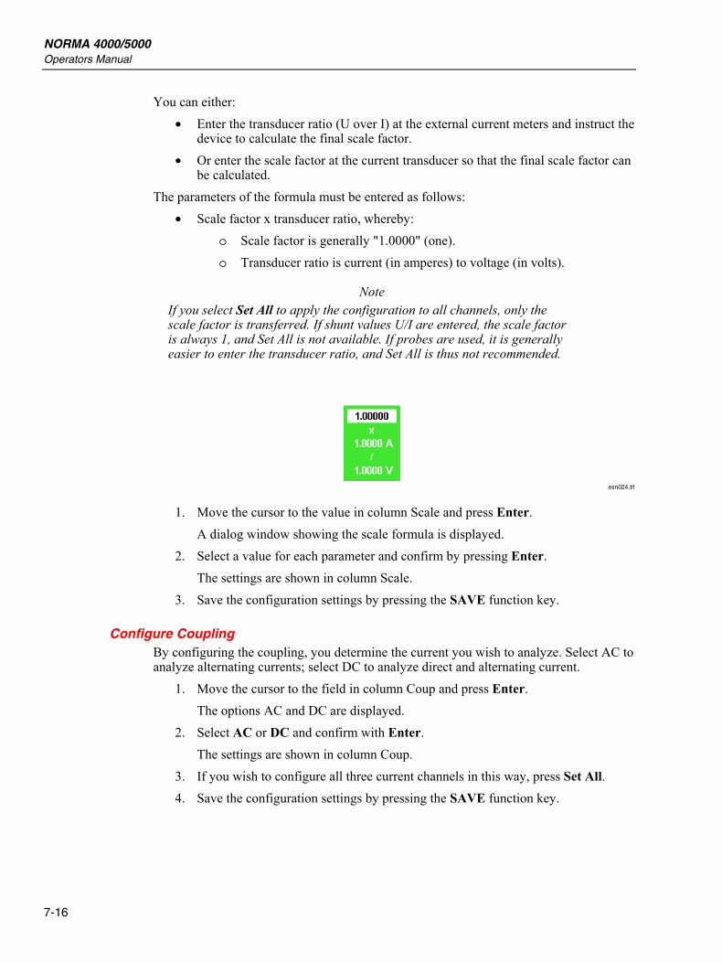
NORMA 4000/5000 Operators Manual
7-16
You can either: • Enter the transducer ratio (U over I) at the external current meters and instruct the
device to calculate the final scale factor. • Or enter the scale factor at the current transducer so that the final scale factor can
be calculated. The parameters of the formula must be entered as follows:
• Scale factor x transducer ratio, whereby: o Scale factor is generally "1.0000" (one). o Transducer ratio is current (in amperes) to voltage (in volts).
Note If you select Set All to apply the configuration to all channels, only the scale factor is transferred. If shunt values U/I are entered, the scale factor is always 1, and Set All is not available. If probes are used, it is generally easier to enter the transducer ratio, and Set All is thus not recommended.
esn024.tif
1. Move the cursor to the value in column Scale and press Enter. A dialog window showing the scale formula is displayed.
2. Select a value for each parameter and confirm by pressing Enter. The settings are shown in column Scale.
3. Save the configuration settings by pressing the SAVE function key.
Configure Coupling By configuring the coupling, you determine the current you wish to analyze. Select AC to analyze alternating currents; select DC to analyze direct and alternating current.
1. Move the cursor to the field in column Coup and press Enter. The options AC and DC are displayed.
2. Select AC or DC and confirm with Enter. The settings are shown in column Coup.
3. If you wish to configure all three current channels in this way, press Set All. 4. Save the configuration settings by pressing the SAVE function key.
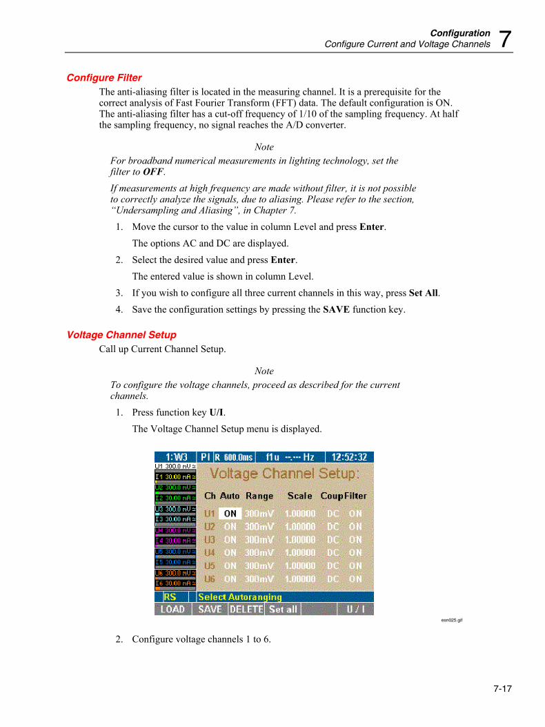
Configuration Configure Current and Voltage Channels 7
7-17
Configure Filter The anti-aliasing filter is located in the measuring channel. It is a prerequisite for the correct analysis of Fast Fourier Transform (FFT) data. The default configuration is ON. The anti-aliasing filter has a cut-off frequency of 1/10 of the sampling frequency. At half the sampling frequency, no signal reaches the A/D converter.
Note For broadband numerical measurements in lighting technology, set the filter to OFF. If measurements at high frequency are made without filter, it is not possible to correctly analyze the signals, due to aliasing. Please refer to the section, “Undersampling and Aliasing”, in Chapter 7.
1. Move the cursor to the value in column Level and press Enter. The options AC and DC are displayed.
2. Select the desired value and press Enter. The entered value is shown in column Level.
3. If you wish to configure all three current channels in this way, press Set All. 4. Save the configuration settings by pressing the SAVE function key.
Voltage Channel Setup Call up Current Channel Setup.
Note To configure the voltage channels, proceed as described for the current channels.
1. Press function key U/I. The Voltage Channel Setup menu is displayed.
esn025.gif
2. Configure voltage channels 1 to 6.
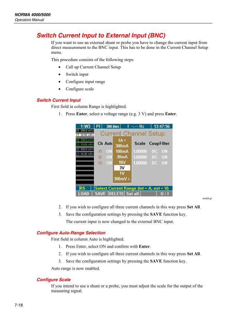
NORMA 4000/5000 Operators Manual
7-18
Switch Current Input to External Input (BNC) If you want to use an external shunt or probe you have to change the current input from direct measurement to the BNC input. This has to be done in the Current Channel Setup menu. This procedure consists of the following steps:
• Call up Current Channel Setup • Switch input • Configure input range • Configure scale
Switch Current Input First field in column Range is highlighted.
1. Press Enter, select a voltage range (e.g. 3 V) and press Enter.
esn026.gif
2. If you wish to configure all three current channels in this way press Set All. 3. Save the configuration settings by pressing the SAVE function key.
The current input is now changed to the external BNC input.
Configure Auto-Range Selection First field in column Auto is highlighted.
1. Press Enter, select ON and confirm with Enter. 2. If you wish to configure all three current channels in this way press Set All. 3. Save the configuration settings by pressing the SAVE function key.
Auto range is now enabled.
Configure Scale If you intend to use a shunt or a probe, you must adjust the scale for the output of the measuring signal.
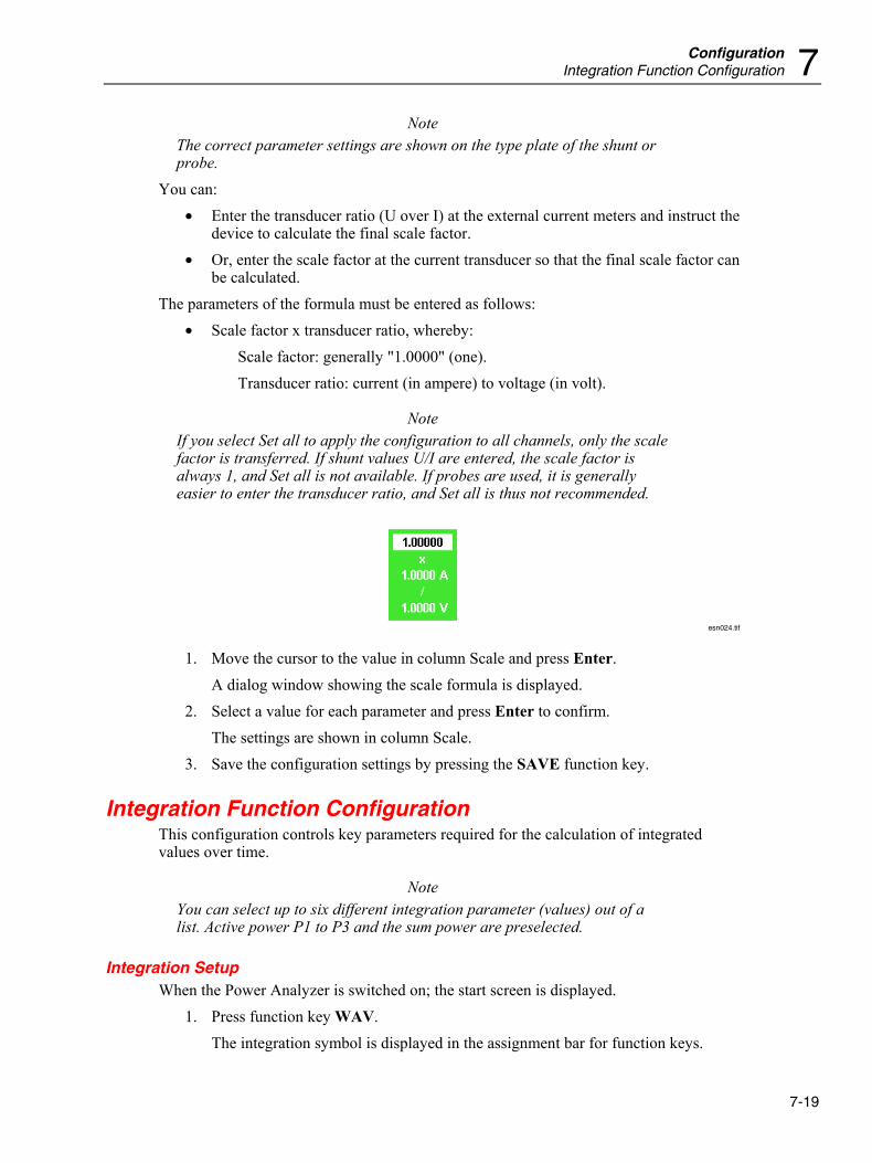
Configuration Integration Function Configuration 7
7-19
Note The correct parameter settings are shown on the type plate of the shunt or probe.
You can: • Enter the transducer ratio (U over I) at the external current meters and instruct the
device to calculate the final scale factor. • Or, enter the scale factor at the current transducer so that the final scale factor can
be calculated. The parameters of the formula must be entered as follows:
• Scale factor x transducer ratio, whereby: Scale factor: generally "1.0000" (one). Transducer ratio: current (in ampere) to voltage (in volt).
Note If you select Set all to apply the configuration to all channels, only the scale factor is transferred. If shunt values U/I are entered, the scale factor is always 1, and Set all is not available. If probes are used, it is generally easier to enter the transducer ratio, and Set all is thus not recommended.
esn024.tif
1. Move the cursor to the value in column Scale and press Enter. A dialog window showing the scale formula is displayed.
2. Select a value for each parameter and press Enter to confirm. The settings are shown in column Scale.
3. Save the configuration settings by pressing the SAVE function key.
Integration Function Configuration This configuration controls key parameters required for the calculation of integrated values over time.
Note You can select up to six different integration parameter (values) out of a list. Active power P1 to P3 and the sum power are preselected.
Integration Setup When the Power Analyzer is switched on; the start screen is displayed.
1. Press function key WAV. The integration symbol is displayed in the assignment bar for function keys.
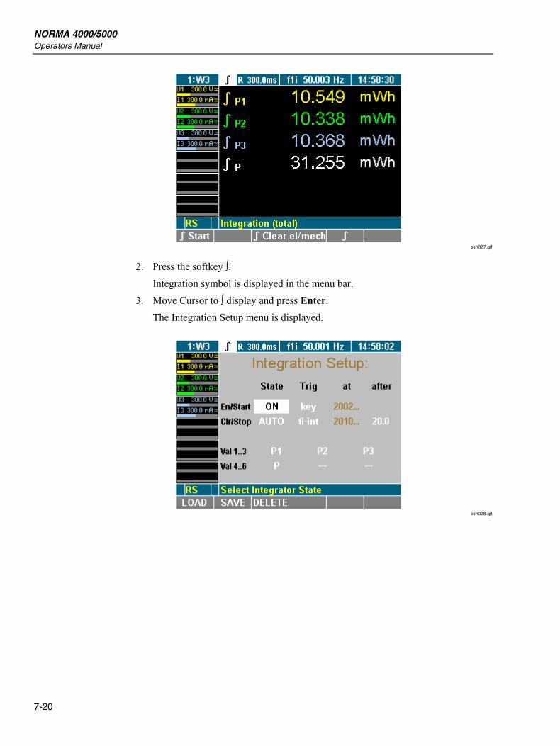
NORMA 4000/5000 Operators Manual
7-20
esn027.gif
2. Press the softkey ∫. Integration symbol is displayed in the menu bar.
3. Move Cursor to ∫ display and press Enter. The Integration Setup menu is displayed.
esn028.gif
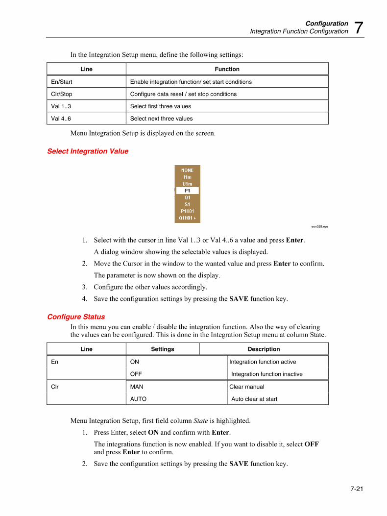
Configuration Integration Function Configuration 7
7-21
In the Integration Setup menu, define the following settings:
Line Function
En/Start Enable integration function/ set start conditions
Clr/Stop Configure data reset / set stop conditions
Val 1..3 Select first three values
Val 4..6 Select next three values
Menu Integration Setup is displayed on the screen.
Select Integration Value
esn029.eps
1. Select with the cursor in line Val 1..3 or Val 4..6 a value and press Enter. A dialog window showing the selectable values is displayed.
2. Move the Cursor in the window to the wanted value and press Enter to confirm. The parameter is now shown on the display.
3. Configure the other values accordingly. 4. Save the configuration settings by pressing the SAVE function key.
Configure Status In this menu you can enable / disable the integration function. Also the way of clearing the values can be configured. This is done in the Integration Setup menu at column State.
Line Settings Description
ON Integration function active En
OFF Integration function inactive
MAN Clear manual Clr
AUTO Auto clear at start
Menu Integration Setup, first field column State is highlighted.
1. Press Enter, select ON and confirm with Enter. The integrations function is now enabled. If you want to disable it, select OFF and press Enter to confirm.
2. Save the configuration settings by pressing the SAVE function key.
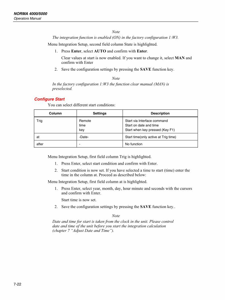
NORMA 4000/5000 Operators Manual
7-22
Note The integration function is enabled (ON) in the factory configuration 1:W3.
Menu Integration Setup, second field column State is highlighted. 1. Press Enter, select AUTO and confirm with Enter.
Clear values at start is now enabled. If you want to change it, select MAN and confirm with Enter
2. Save the configuration settings by pressing the SAVE function key.
Note In the factory configuration 1:W3 the function clear manual (MAN) is preselected.
Configure Start You can select different start conditions:
Column Settings Description
Trig Remote time key
Start via Interface command Start on date and time Start when key pressed (Key F1)
at -Date- Start time(only active at Trig time)
after - No function
Menu Integration Setup, first field column Trig is highlighted.
1. Press Enter, select start condition and confirm with Enter. 2. Start condition is now set. If you have selected a time to start (time) enter the
time in the column at. Proceed as described below: Menu Integration Setup, first field column at is highlighted.
1. Press Enter, select year, month, day, hour minute and seconds with the cursors and confirm with Enter. Start time is now set.
2. Save the configuration settings by pressing the SAVE function key..
Note Date and time for start is taken from the clock in the unit. Please control date and time of the unit before you start the integration calculation (chapter 7 “Adjust Date and Time”).
Configuration Save Configuration 7
7-23
Configure Stop You can select different stop conditions:
Column Settings Description
Remote Stop via Interface command
time Stop at date and time
key Stop when key pressed (Key F2)
Trig
ti-int Stop after time window
at -Date- Stop on date and time (only active at Trig time)
after -time- Integrations time window in sec. (only active at Trig ti-int)
Menu Integration Setup, second field column Trig marker.
• Press Enter, select stop condition and confirm with Enter. • Stop condition is now set. If you have selected a time to start (time) enter the
time in the column at. Proceed as described below: Menu Integration Setup, first field column at is highlighted.
• Press Enter, select year, month, day, hour minute and seconds with the cursors and press Enter to confirm.
• Stop time is now set. If you have an integration time window selected (ti-int) proceed as follow:
Menu Integration Setup, second field column after is highlighted. • Press Enter, select time with the cursors and confirm with Enter.
Stop time is now set. • Save the configuration settings by pressing the SAVE function key.
Save Configuration A configuration menu is displayed on the screen.
1. Press function key SAVE. A list showing all existing configurations is displayed.
2. Select a configuration (for example, 10:USER) and press Enter to confirm. The configuration is now being saved with the new name. The name of the new configuration, 10:USER, is displayed in the menu item.
At the next startup of the device, the last saved and loaded configuration is applied by default.
NORMA 4000/5000 Operators Manual
7-24
Delete Configuration A configuration menu is displayed on the screen.
1. Press function key DELETE. A list showing all existing configurations is displayed.
2. Select a configuration (for example. 10:USER) and confirm with Enter. The configuration is now being deleted.
3. Press Enter or Esc to return to the previous screen.
Undersampling and Aliasing If you want to make signal analyzes like DSO (scope) or harmonic analyzes (FFT) with a digital sampling procedures, you need to take care about Shannon’s sampling theorem that says: “The sample frequency must be minimum double than the highest signal frequency”. If you do not keep this rule, you will get results (frequencies or waveforms) that do not exist in truth (in other words, aliasing). If you want to measure a numeric time-based mean values like rms, rectified mean, mean, you do need not observe Shannon’s theorem. For the precision of the results, only the number of samples is important, not the sampling frequency (average time >> cycle duration). The sampling signal must be statistical independent, which means the sampling frequency must not be close to or a multiple of the signal frequency.
Note To work in the “undersampling mode”, the anti-aliasing filter must be turned OFF at the current and voltage channel (see the earlier section “Configure Current and Voltage Channels” in this chapter).
8-1
Chapter 8 Measuring Process
Title Page
Introduction........................................................................................................ 8-3 Prior to Measuring ............................................................................................. 8-3
Measuring with Default Configuration.......................................................... 8-3 Measuring with User-Defined Configuration................................................ 8-3
Measure Voltage, Current and Power................................................................ 8-4 Measured Values for Individual Channels .................................................... 8-4
View the Values of One Channel.............................................................. 8-4 View Detailed Values of One Channel ..................................................... 8-4
View Totals of all Measured Values ............................................................. 8-7 View Totals ............................................................................................... 8-7 View Efficiency ........................................................................................ 8-8
Compare Measured Values............................................................................ 8-8 View Fundamentals ....................................................................................... 8-10
View Fundamentals................................................................................... 8-10 View Fundamentals Details ...................................................................... 8-10
User-Defined Screen View............................................................................ 8-12 View User-Defined Screen ....................................................................... 8-12 Select Numeric Values .............................................................................. 8-13 Change User-Defined Display Size........................................................... 8-14 Save User Defined Screen......................................................................... 8-14 Back to Common Numeric Screen............................................................ 8-14
Change View Mode ........................................................................................... 8-14 Numerical Display......................................................................................... 8-15 Vector Graphs................................................................................................ 8-15
View Vector Graphs.................................................................................. 8-15 Adjust Scale .............................................................................................. 8-15
Oscilloscope Curves ...................................................................................... 8-16 View Oscilloscope Display ....................................................................... 8-16 Adjust Axial Scale..................................................................................... 8-17 Adjust Zero ............................................................................................... 8-17
Recorder View............................................................................................... 8-17 Fast Fourier Analysis ......................................................................................... 8-18
FFT Mode...................................................................................................... 8-19 Adjust Scale .............................................................................................. 8-19 View Details of a Measured Value ........................................................... 8-20

NORMA 4000/5000 Operators Manual
8-2
Set Frequency Range................................................................................. 8-20 Change View Mode................................................................................... 8-21
Harmonic Order Mode .................................................................................. 8-22 View Harmonics........................................................................................ 8-22
Harmonic Order Mode Related to Fundamental in %................................... 8-23 View Spectrum Relative to H01 ............................................................... 8-23
Integration Function/Electrical Work ................................................................ 8-24 Save and Print Measurements............................................................................ 8-26
Save Measurements ....................................................................................... 8-26 Print Measurements ....................................................................................... 8-26
Measuring Process Introduction 8
8-3
Introduction The Fluke NORMA 4000/5000 Power Analyzer is designed for the measuring of currents and voltages for up to three different channels. The Power Analyzer calculates rms values, real, apparent and idle power, and other derived values. The accuracy is thereby not affected by the wave form, frequency, or phase shift. Harmonics are output to maximum half the sampling frequency. You have the option to apply the default settings or a user-defined configuration. If you wish to use a user-defined configuration, you must first define and save the respective settings and then load the relevant configuration (see, section "Configuration" in Chapter 7). The Power Analyzer begins to measure as soon as the measuring arrangement is set and the device switched on.
Prior to Measuring Connect Power Analyzer to the mains (power) socket.
1. Check the measuring connections at the Power Analyzer. 2. Switch on the Power Analyzer.
Measuring with Default Configuration If you want to complete an analysis using the default configuration, no additional steps are required. Ensure that the factory configuration is loaded (see, "Load Configuration" in Chapter 7).
Measuring with User-Defined Configuration If you want to complete an analysis with a user-defined configuration, load the respective configuration (see "Configuration" in Chapter 7).
Note If you want to measure with external shunt or probe, make sure that there is no signal connected at the direct current inputs. Signals on both inputs (external- and direct-current input) can damage the measurement unit.
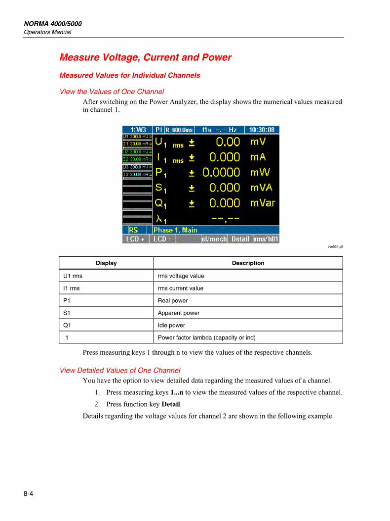
NORMA 4000/5000 Operators Manual
8-4
Measure Voltage, Current and Power
Measured Values for Individual Channels
View the Values of One Channel After switching on the Power Analyzer, the display shows the numerical values measured in channel 1.
esn030.gif
Display Description
U1 rms rms voltage value
I1 rms rms current value
P1 Real power
S1 Apparent power
Q1 Idle power
1 Power factor lambda (capacity or ind)
Press measuring keys 1 through n to view the values of the respective channels.
View Detailed Values of One Channel You have the option to view detailed data regarding the measured values of a channel.
1. Press measuring keys 1...n to view the measured values of the respective channel. 2. Press function key Detail.
Details regarding the voltage values for channel 2 are shown in the following example.
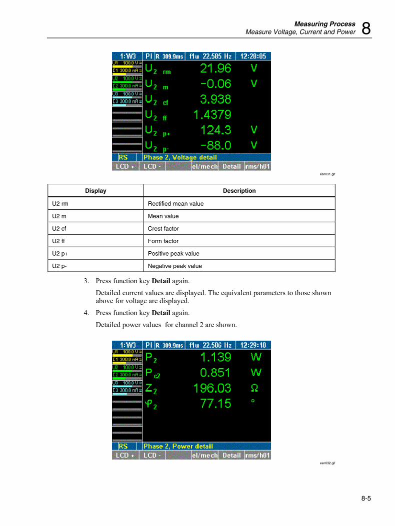
Measuring Process Measure Voltage, Current and Power 8
8-5
esn031.gif
Display Description
U2 rm Rectified mean value
U2 m Mean value
U2 cf Crest factor
U2 ff Form factor
U2 p+ Positive peak value
U2 p- Negative peak value
3. Press function key Detail again. Detailed current values are displayed. The equivalent parameters to those shown above for voltage are displayed.
4. Press function key Detail again. Detailed power values for channel 2 are shown.
esn032.gif
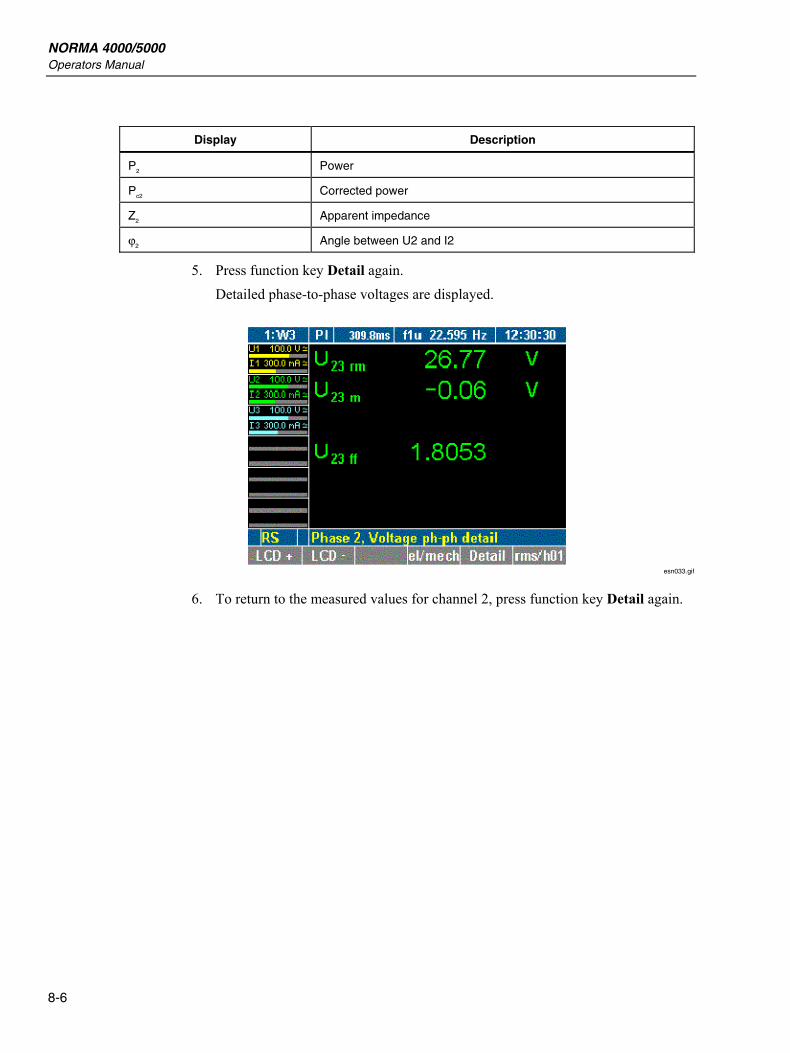
NORMA 4000/5000 Operators Manual
8-6
Display Description
P2 Power
Pc2 Corrected power
Z2 Apparent impedance
ϕ2 Angle between U2 and I2
5. Press function key Detail again. Detailed phase-to-phase voltages are displayed.
esn033.gif
6. To return to the measured values for channel 2, press function key Detail again.
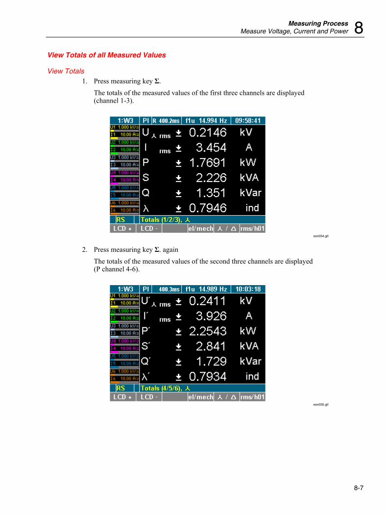
Measuring Process Measure Voltage, Current and Power 8
8-7
View Totals of all Measured Values
View Totals 1. Press measuring key Σ.
The totals of the measured values of the first three channels are displayed (channel 1-3).
esn034.gif
2. Press measuring key Σ. again The totals of the measured values of the second three channels are displayed (P channel 4-6).
esn035.gif
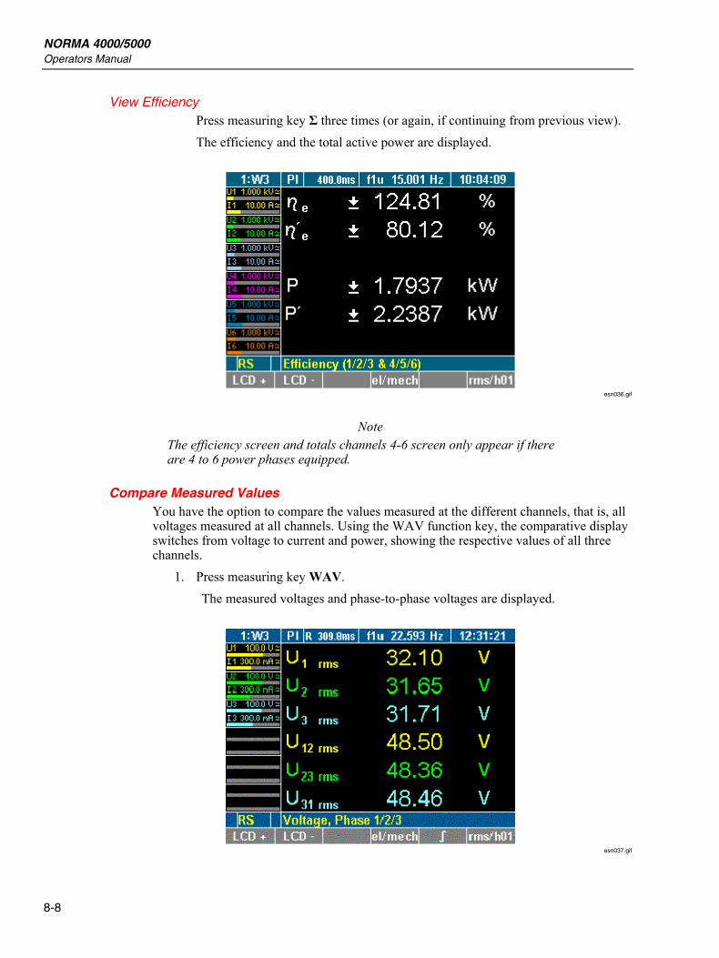
NORMA 4000/5000 Operators Manual
8-8
View Efficiency Press measuring key Σ three times (or again, if continuing from previous view). The efficiency and the total active power are displayed.
esn036.gif
Note The efficiency screen and totals channels 4-6 screen only appear if there are 4 to 6 power phases equipped.
Compare Measured Values You have the option to compare the values measured at the different channels, that is, all voltages measured at all channels. Using the WAV function key, the comparative display switches from voltage to current and power, showing the respective values of all three channels.
1. Press measuring key WAV. The measured voltages and phase-to-phase voltages are displayed.
esn037.gif
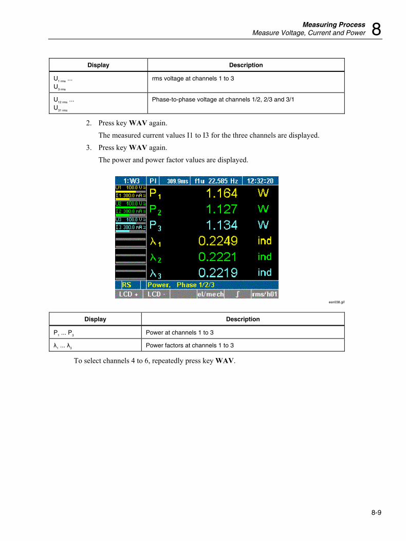
Measuring Process Measure Voltage, Current and Power 8
8-9
Display Description
U1 rms ... U3 rms
rms voltage at channels 1 to 3
U12 rms ... U31 rms
Phase-to-phase voltage at channels 1/2, 2/3 and 3/1
2. Press key WAV again. The measured current values I1 to I3 for the three channels are displayed.
3. Press key WAV again. The power and power factor values are displayed.
esn038.gif
Display Description
P1 ... P3 Power at channels 1 to 3
λ1 ... λ3 Power factors at channels 1 to 3
To select channels 4 to 6, repeatedly press key WAV.
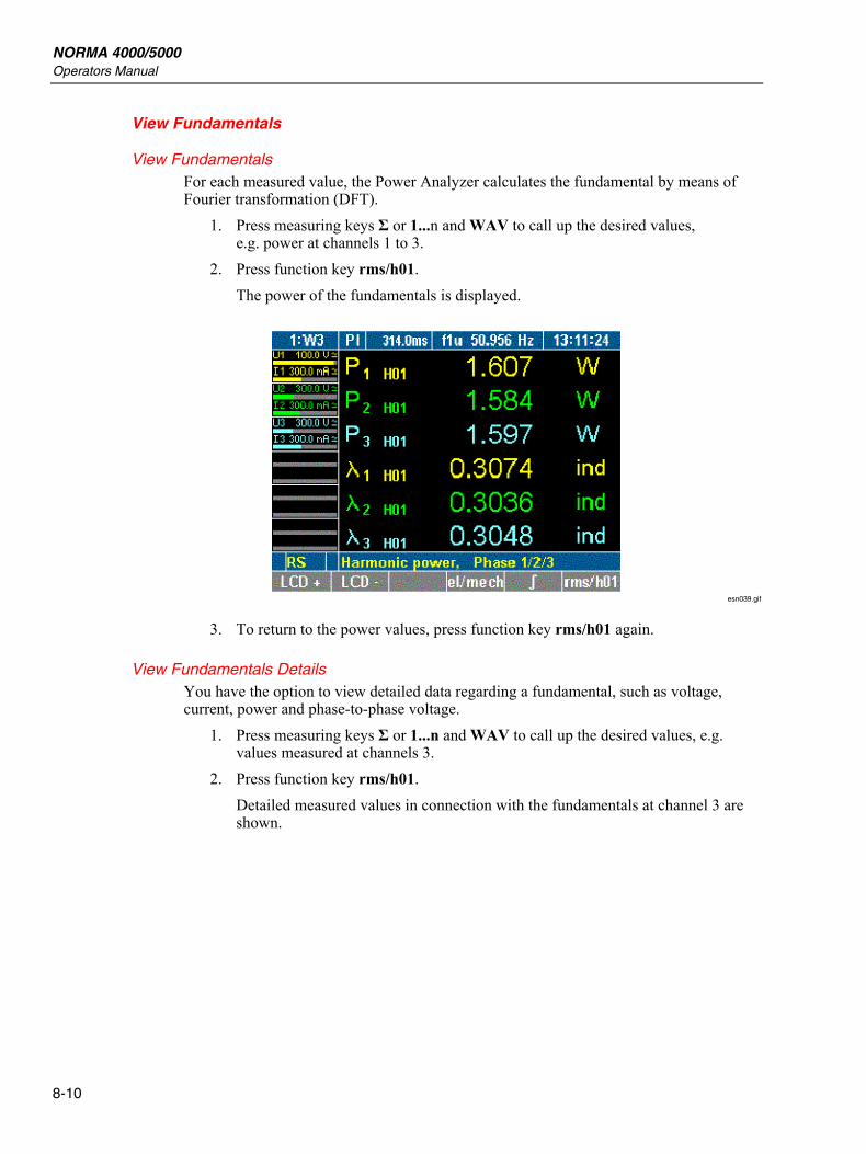
NORMA 4000/5000 Operators Manual
8-10
View Fundamentals
View Fundamentals For each measured value, the Power Analyzer calculates the fundamental by means of Fourier transformation (DFT).
1. Press measuring keys Σ or 1...n and WAV to call up the desired values, e.g. power at channels 1 to 3.
2. Press function key rms/h01. The power of the fundamentals is displayed.
esn039.gif
3. To return to the power values, press function key rms/h01 again.
View Fundamentals Details You have the option to view detailed data regarding a fundamental, such as voltage, current, power and phase-to-phase voltage.
1. Press measuring keys Σ or 1...n and WAV to call up the desired values, e.g. values measured at channels 3.
2. Press function key rms/h01. Detailed measured values in connection with the fundamentals at channel 3 are shown.
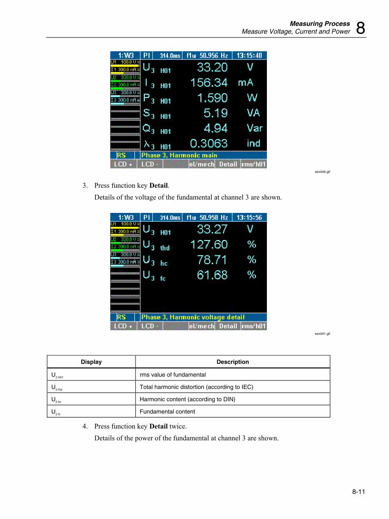
Measuring Process Measure Voltage, Current and Power 8
8-11
esn040.gif
3. Press function key Detail. Details of the voltage of the fundamental at channel 3 are shown.
esn041.gif
Display Description
U2 H01 rms value of fundamental
U2 thd Total harmonic distortion (according to IEC)
U2 hc Harmonic content (according to DIN)
U2 fc Fundamental content
4. Press function key Detail twice. Details of the power of the fundamental at channel 3 are shown.
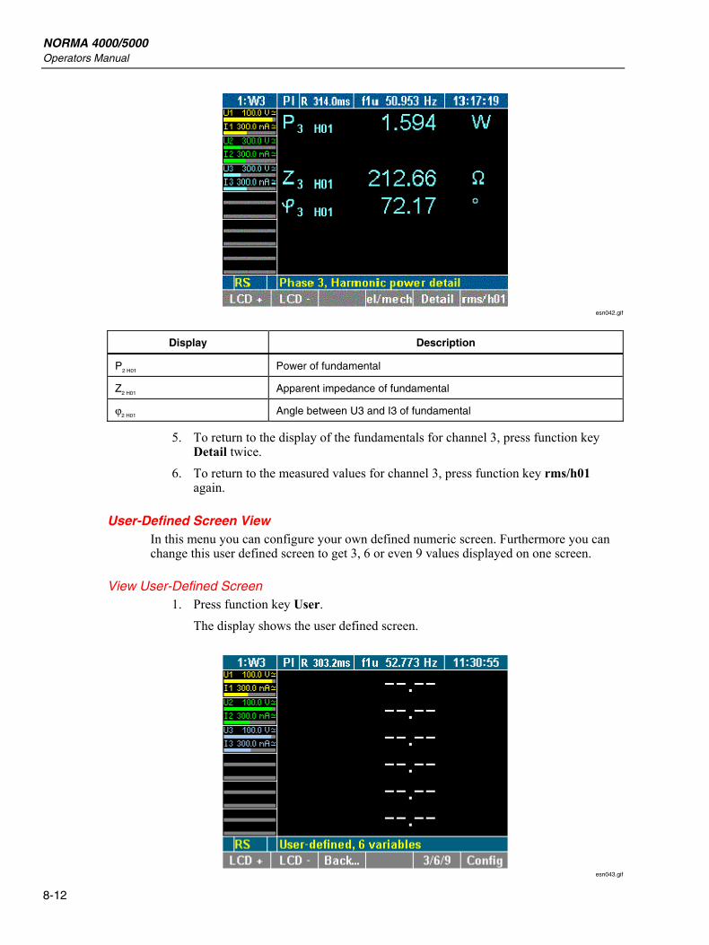
NORMA 4000/5000 Operators Manual
8-12
esn042.gif
Display Description
P2 H01 Power of fundamental
Z2 H01 Apparent impedance of fundamental
ϕ2 H01 Angle between U3 and I3 of fundamental
5. To return to the display of the fundamentals for channel 3, press function key Detail twice.
6. To return to the measured values for channel 3, press function key rms/h01 again.
User-Defined Screen View In this menu you can configure your own defined numeric screen. Furthermore you can change this user defined screen to get 3, 6 or even 9 values displayed on one screen.
View User-Defined Screen 1. Press function key User.
The display shows the user defined screen.
esn043.gif
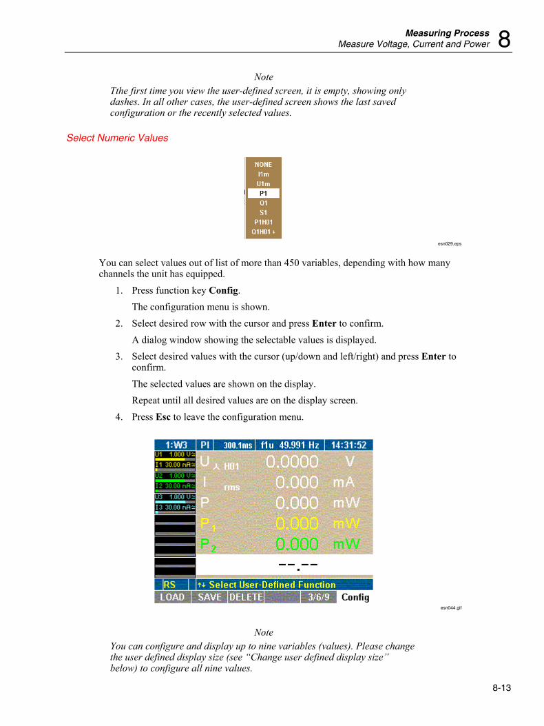
Measuring Process Measure Voltage, Current and Power 8
8-13
Note Tthe first time you view the user-defined screen, it is empty, showing only dashes. In all other cases, the user-defined screen shows the last saved configuration or the recently selected values.
Select Numeric Values
esn029.eps
You can select values out of list of more than 450 variables, depending with how many channels the unit has equipped.
1. Press function key Config. The configuration menu is shown.
2. Select desired row with the cursor and press Enter to confirm. A dialog window showing the selectable values is displayed.
3. Select desired values with the cursor (up/down and left/right) and press Enter to confirm. The selected values are shown on the display. Repeat until all desired values are on the display screen.
4. Press Esc to leave the configuration menu.
esn044.gif
Note You can configure and display up to nine variables (values). Please change the user defined display size (see “Change user defined display size” below) to configure all nine values.
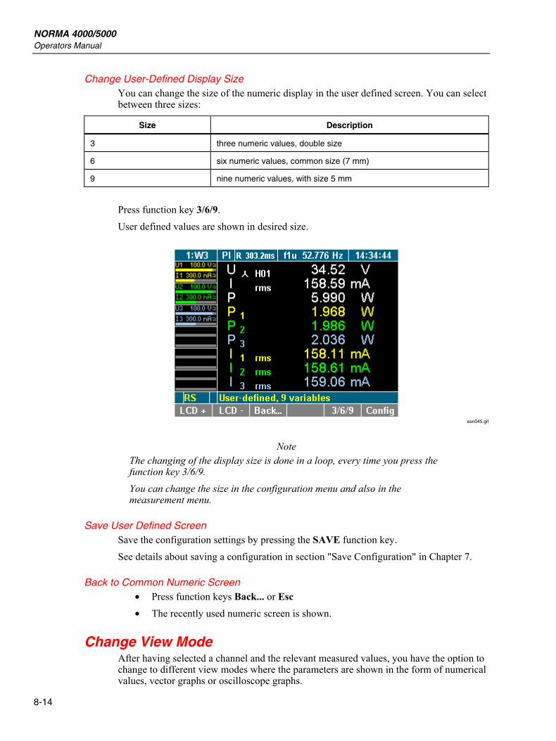
NORMA 4000/5000 Operators Manual
8-14
Change User-Defined Display Size You can change the size of the numeric display in the user defined screen. You can select between three sizes:
Size Description
3 three numeric values, double size
6 six numeric values, common size (7 mm)
9 nine numeric values, with size 5 mm
Press function key 3/6/9. User defined values are shown in desired size.
esn045.gif
Note The changing of the display size is done in a loop, every time you press the function key 3/6/9. You can change the size in the configuration menu and also in the measurement menu.
Save User Defined Screen Save the configuration settings by pressing the SAVE function key. See details about saving a configuration in section "Save Configuration" in Chapter 7.
Back to Common Numeric Screen • Press function keys Back... or Esc • The recently used numeric screen is shown.
Change View Mode After having selected a channel and the relevant measured values, you have the option to change to different view modes where the parameters are shown in the form of numerical values, vector graphs or oscilloscope graphs.
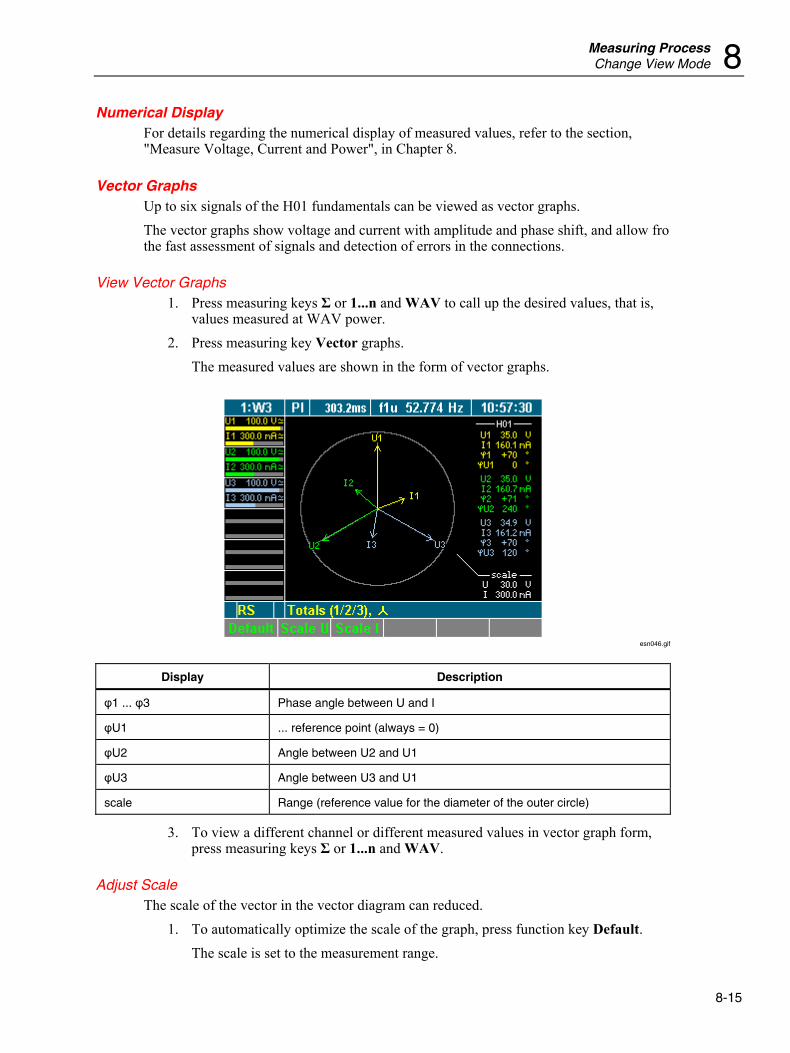
Measuring Process Change View Mode 8
8-15
Numerical Display For details regarding the numerical display of measured values, refer to the section, "Measure Voltage, Current and Power", in Chapter 8.
Vector Graphs Up to six signals of the H01 fundamentals can be viewed as vector graphs. The vector graphs show voltage and current with amplitude and phase shift, and allow fro the fast assessment of signals and detection of errors in the connections.
View Vector Graphs 1. Press measuring keys Σ or 1...n and WAV to call up the desired values, that is,
values measured at WAV power. 2. Press measuring key Vector graphs.
The measured values are shown in the form of vector graphs.
esn046.gif
Display Description
φ1 ... φ3 Phase angle between U and I
φU1 ... reference point (always = 0)
φU2 Angle between U2 and U1
φU3 Angle between U3 and U1
scale Range (reference value for the diameter of the outer circle)
3. To view a different channel or different measured values in vector graph form, press measuring keys Σ or 1...n and WAV.
Adjust Scale The scale of the vector in the vector diagram can reduced.
1. To automatically optimize the scale of the graph, press function key Default. The scale is set to the measurement range.
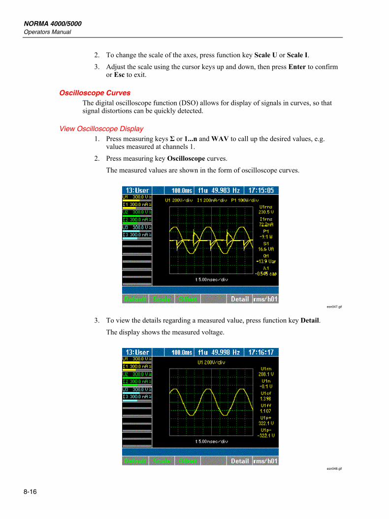
NORMA 4000/5000 Operators Manual
8-16
2. To change the scale of the axes, press function key Scale U or Scale I. 3. Adjust the scale using the cursor keys up and down, then press Enter to confirm
or Esc to exit.
Oscilloscope Curves The digital oscilloscope function (DSO) allows for display of signals in curves, so that signal distortions can be quickly detected.
View Oscilloscope Display 1. Press measuring keys Σ or 1...n and WAV to call up the desired values, e.g.
values measured at channels 1. 2. Press measuring key Oscilloscope curves.
The measured values are shown in the form of oscilloscope curves.
esn047.gif
3. To view the details regarding a measured value, press function key Detail. The display shows the measured voltage.
esn048.gif
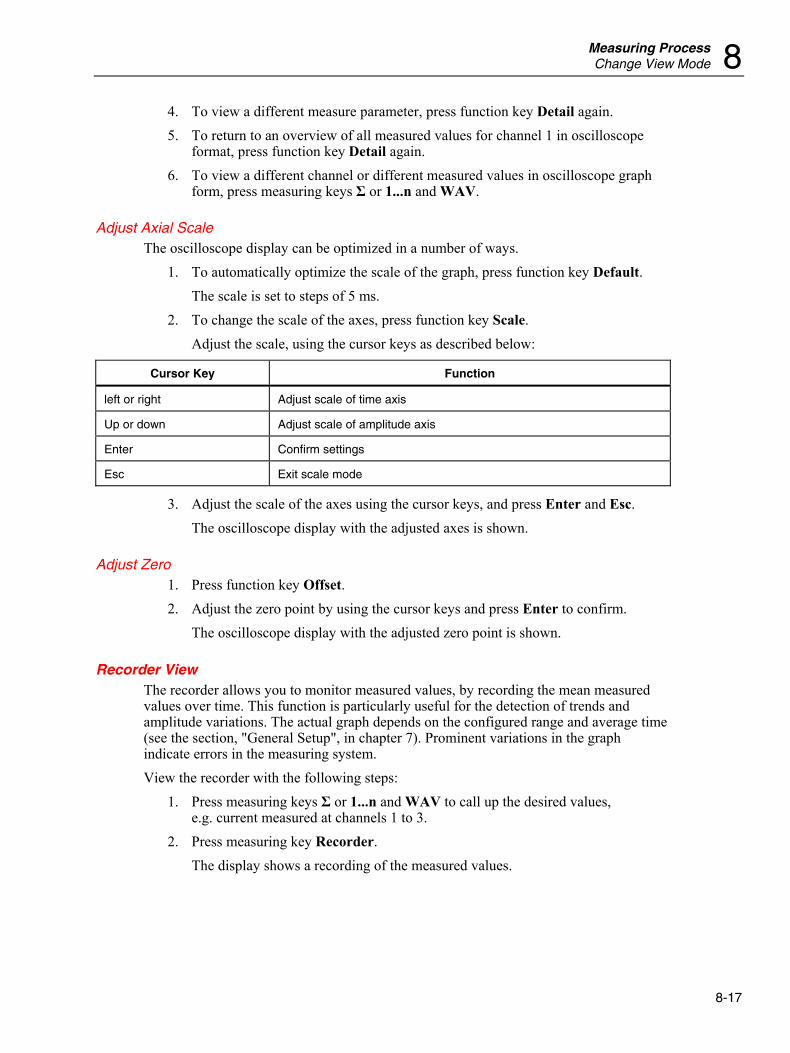
Measuring Process Change View Mode 8
8-17
4. To view a different measure parameter, press function key Detail again. 5. To return to an overview of all measured values for channel 1 in oscilloscope
format, press function key Detail again. 6. To view a different channel or different measured values in oscilloscope graph
form, press measuring keys Σ or 1...n and WAV.
Adjust Axial Scale The oscilloscope display can be optimized in a number of ways.
1. To automatically optimize the scale of the graph, press function key Default. The scale is set to steps of 5 ms.
2. To change the scale of the axes, press function key Scale. Adjust the scale, using the cursor keys as described below:
Cursor Key Function
left or right Adjust scale of time axis
Up or down Adjust scale of amplitude axis
Enter Confirm settings
Esc Exit scale mode
3. Adjust the scale of the axes using the cursor keys, and press Enter and Esc. The oscilloscope display with the adjusted axes is shown.
Adjust Zero 1. Press function key Offset. 2. Adjust the zero point by using the cursor keys and press Enter to confirm.
The oscilloscope display with the adjusted zero point is shown.
Recorder View The recorder allows you to monitor measured values, by recording the mean measured values over time. This function is particularly useful for the detection of trends and amplitude variations. The actual graph depends on the configured range and average time (see the section, "General Setup", in chapter 7). Prominent variations in the graph indicate errors in the measuring system. View the recorder with the following steps:
1. Press measuring keys Σ or 1...n and WAV to call up the desired values, e.g. current measured at channels 1 to 3.
2. Press measuring key Recorder. The display shows a recording of the measured values.
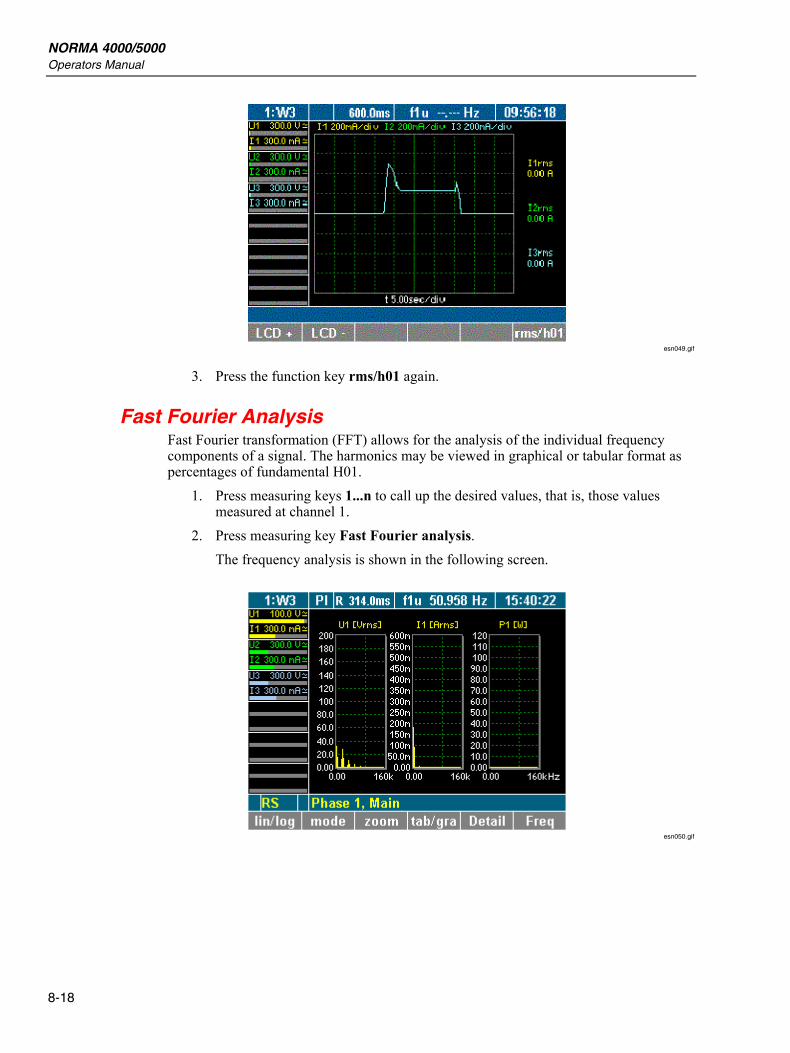
NORMA 4000/5000 Operators Manual
8-18
esn049.gif
3. Press the function key rms/h01 again.
Fast Fourier Analysis Fast Fourier transformation (FFT) allows for the analysis of the individual frequency components of a signal. The harmonics may be viewed in graphical or tabular format as percentages of fundamental H01.
1. Press measuring keys 1...n to call up the desired values, that is, those values measured at channel 1.
2. Press measuring key Fast Fourier analysis. The frequency analysis is shown in the following screen.
esn050.gif
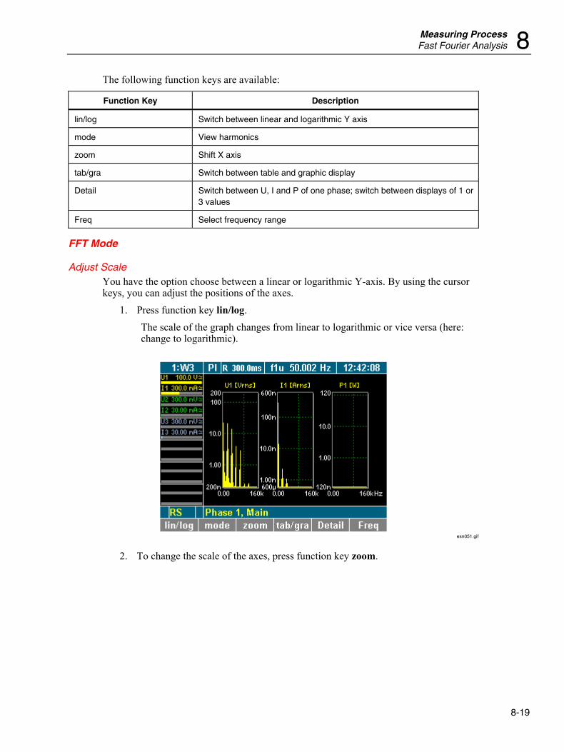
Measuring Process Fast Fourier Analysis 8
8-19
The following function keys are available:
Function Key Description
lin/log Switch between linear and logarithmic Y axis
mode View harmonics
zoom Shift X axis
tab/gra Switch between table and graphic display
Detail Switch between U, I and P of one phase; switch between displays of 1 or 3 values
Freq Select frequency range
FFT Mode
Adjust Scale You have the option choose between a linear or logarithmic Y-axis. By using the cursor keys, you can adjust the positions of the axes.
1. Press function key lin/log. The scale of the graph changes from linear to logarithmic or vice versa (here: change to logarithmic).
esn051.gif
2. To change the scale of the axes, press function key zoom.
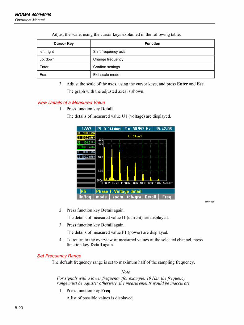
NORMA 4000/5000 Operators Manual
8-20
Adjust the scale, using the cursor keys explained in the following table:
Cursor Key Function
left, right Shift frequency axis
up, down Change frequency
Enter Confirm settings
Esc Exit scale mode
3. Adjust the scale of the axes, using the cursor keys, and press Enter and Esc. The graph with the adjusted axes is shown.
View Details of a Measured Value 1. Press function key Detail.
The details of measured value U1 (voltage) are displayed.
esn052.gif
2. Press function key Detail again. The details of measured value I1 (current) are displayed.
3. Press function key Detail again. The details of measured value P1 (power) are displayed.
4. To return to the overview of measured values of the selected channel, press function key Detail again.
Set Frequency Range The default frequency range is set to maximum half of the sampling frequency.
Note For signals with a lower frequency (for example, 10 Hz), the frequency range must be adjuste; otherwise, the measurements would be inaccurate.
1. Press function key Freq. A list of possible values is displayed.
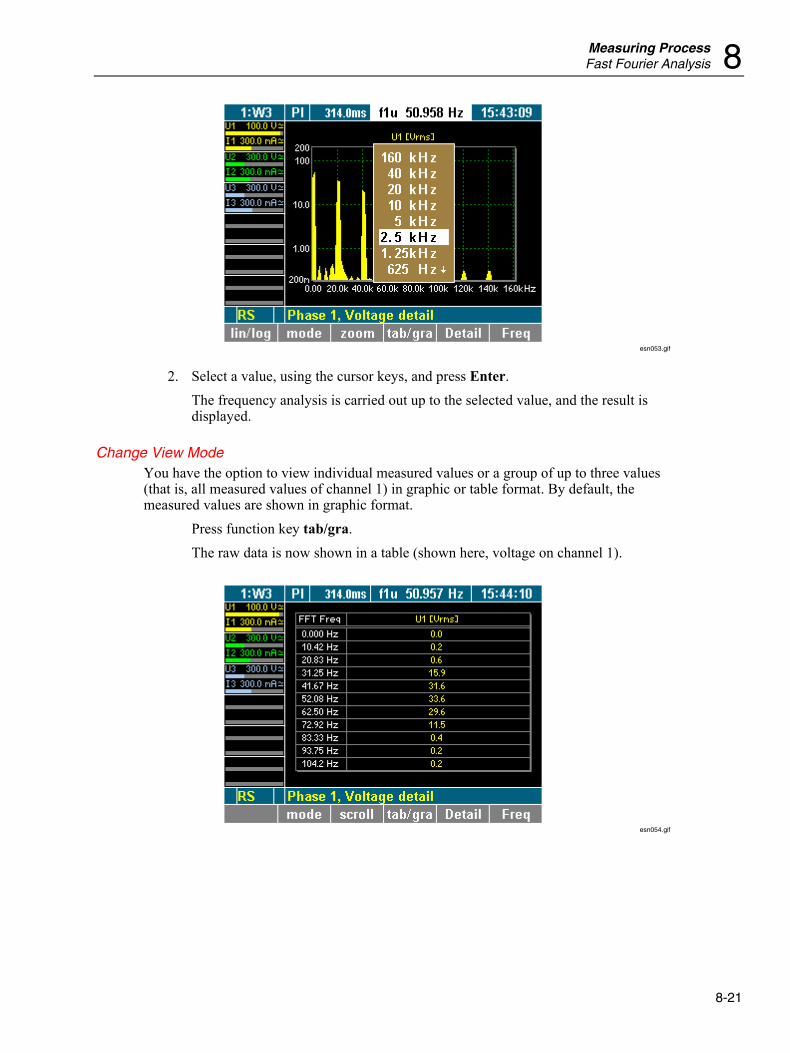
Measuring Process Fast Fourier Analysis 8
8-21
esn053.gif
2. Select a value, using the cursor keys, and press Enter. The frequency analysis is carried out up to the selected value, and the result is displayed.
Change View Mode You have the option to view individual measured values or a group of up to three values (that is, all measured values of channel 1) in graphic or table format. By default, the measured values are shown in graphic format.
Press function key tab/gra. The raw data is now shown in a table (shown here, voltage on channel 1).
esn054.gif
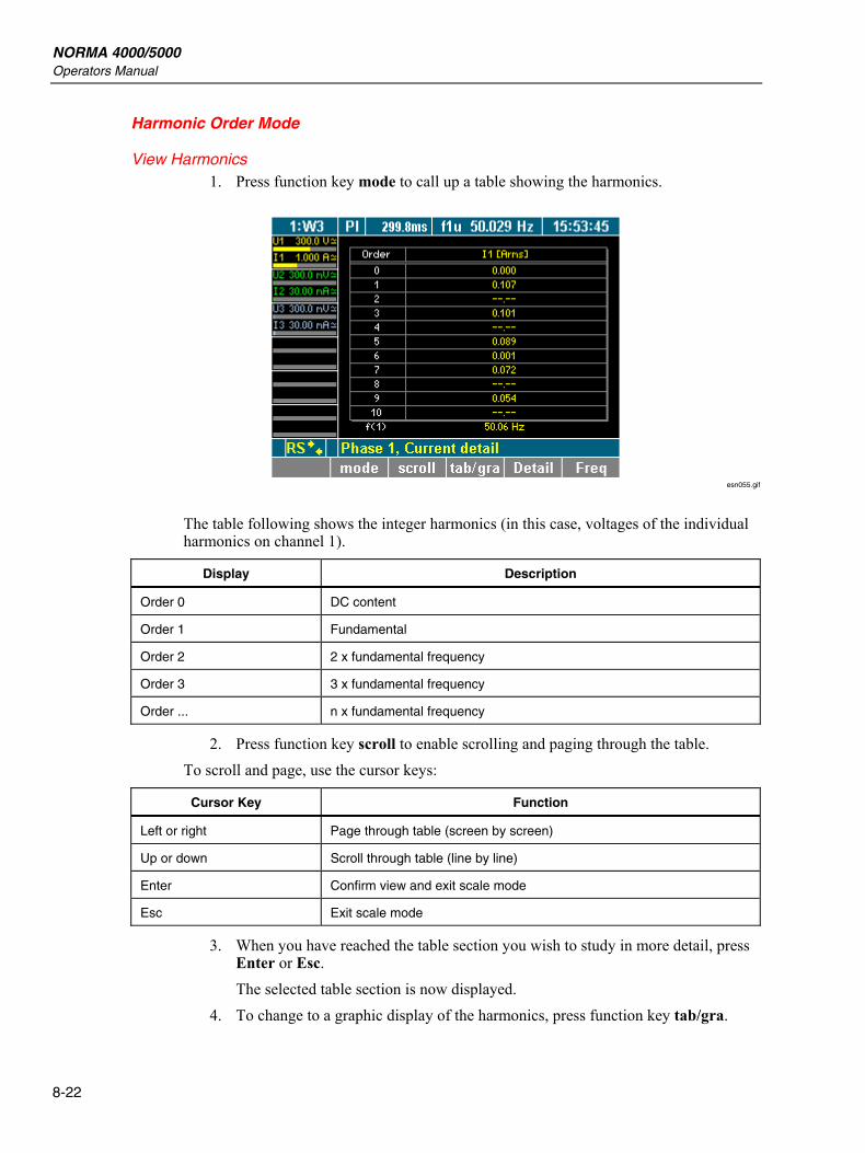
NORMA 4000/5000 Operators Manual
8-22
Harmonic Order Mode
View Harmonics 1. Press function key mode to call up a table showing the harmonics.
esn055.gif
The table following shows the integer harmonics (in this case, voltages of the individual harmonics on channel 1).
Display Description
Order 0 DC content
Order 1 Fundamental
Order 2 2 x fundamental frequency
Order 3 3 x fundamental frequency
Order ... n x fundamental frequency
2. Press function key scroll to enable scrolling and paging through the table. To scroll and page, use the cursor keys:
Cursor Key Function
Left or right Page through table (screen by screen)
Up or down Scroll through table (line by line)
Enter Confirm view and exit scale mode
Esc Exit scale mode
3. When you have reached the table section you wish to study in more detail, press Enter or Esc. The selected table section is now displayed.
4. To change to a graphic display of the harmonics, press function key tab/gra.
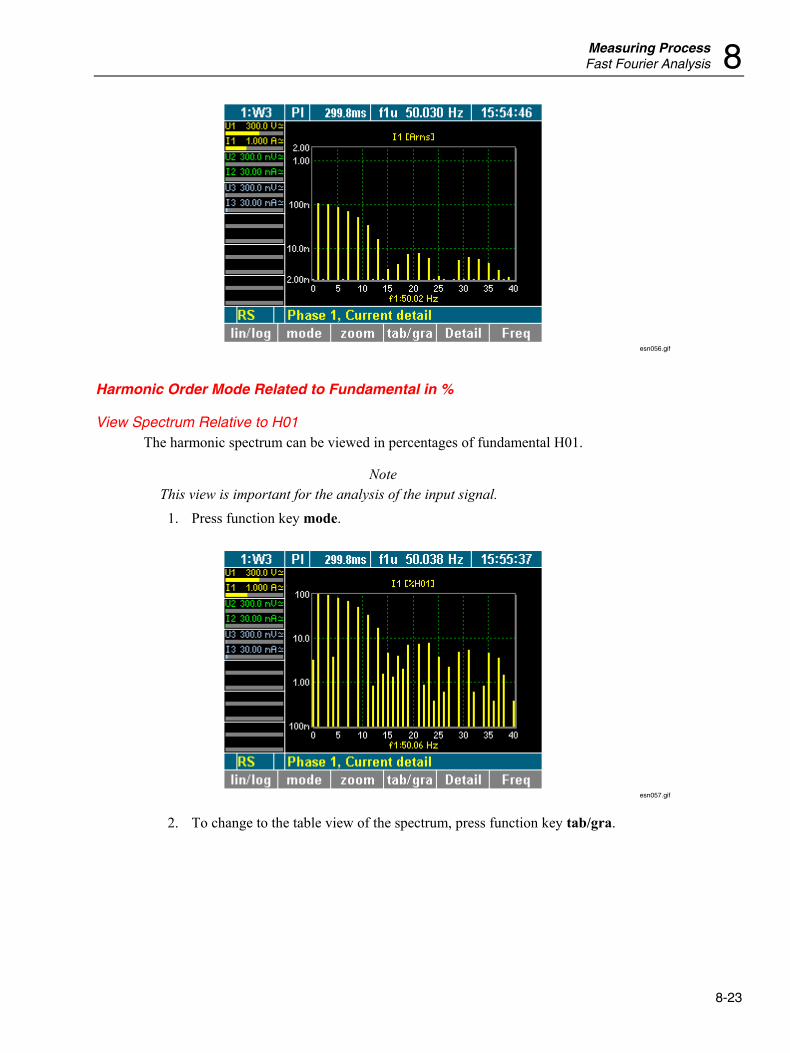
Measuring Process Fast Fourier Analysis 8
8-23
esn056.gif
Harmonic Order Mode Related to Fundamental in %
View Spectrum Relative to H01 The harmonic spectrum can be viewed in percentages of fundamental H01.
Note This view is important for the analysis of the input signal.
1. Press function key mode.
esn057.gif
2. To change to the table view of the spectrum, press function key tab/gra.
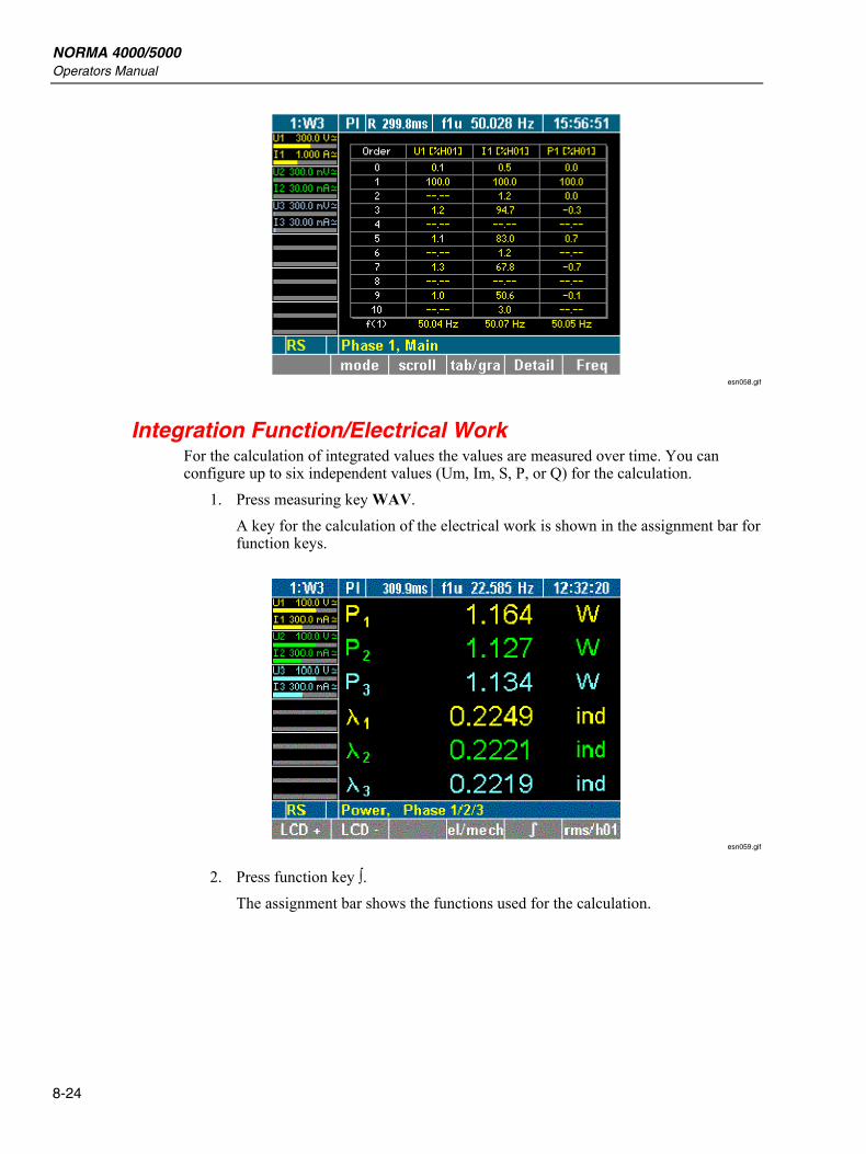
NORMA 4000/5000 Operators Manual
8-24
esn058.gif
Integration Function/Electrical Work For the calculation of integrated values the values are measured over time. You can configure up to six independent values (Um, Im, S, P, or Q) for the calculation.
1. Press measuring key WAV. A key for the calculation of the electrical work is shown in the assignment bar for function keys.
esn059.gif
2. Press function key ∫. The assignment bar shows the functions used for the calculation.
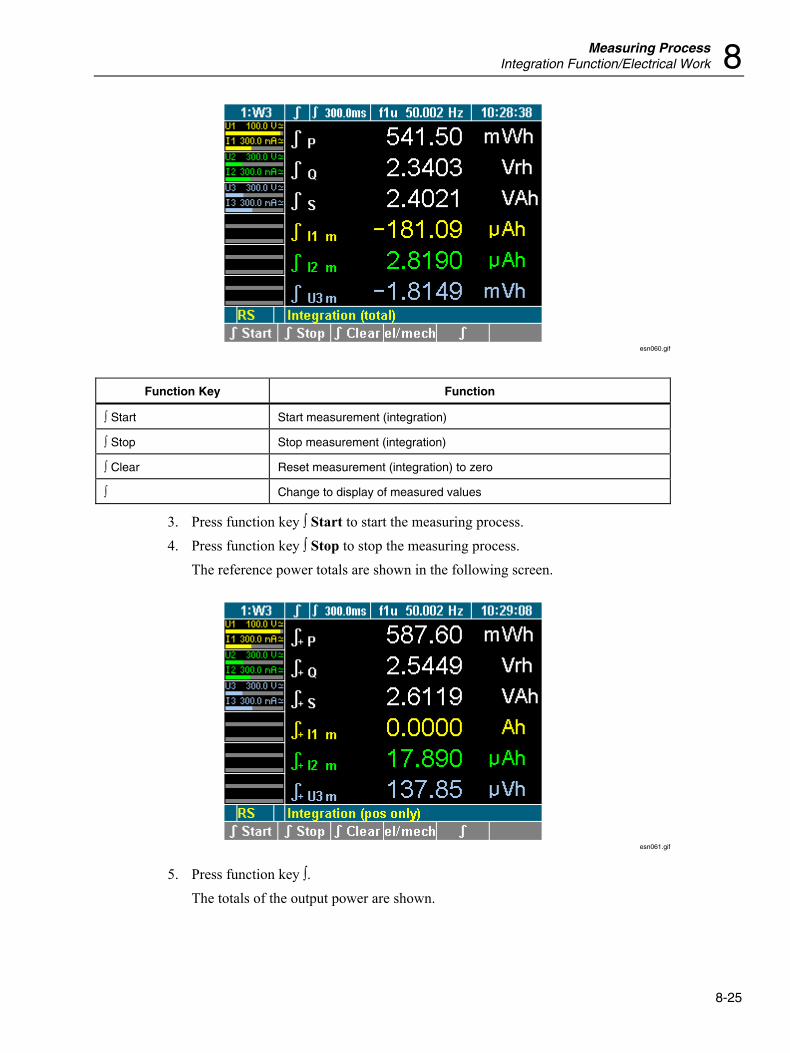
Measuring Process Integration Function/Electrical Work 8
8-25
esn060.gif
Function Key Function
∫ Start Start measurement (integration)
∫ Stop Stop measurement (integration)
∫ Clear Reset measurement (integration) to zero
∫ Change to display of measured values
3. Press function key ∫ Start to start the measuring process. 4. Press function key ∫ Stop to stop the measuring process.
The reference power totals are shown in the following screen.
esn061.gif
5. Press function key ∫. The totals of the output power are shown.
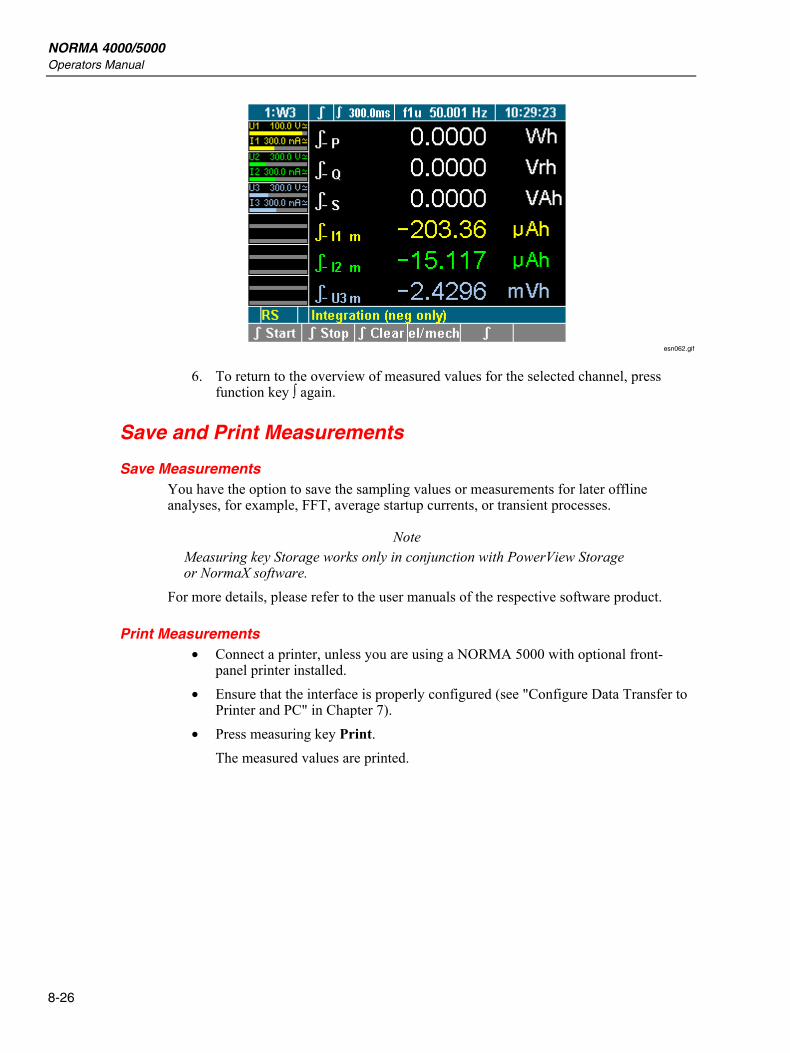
NORMA 4000/5000 Operators Manual
8-26
esn062.gif
6. To return to the overview of measured values for the selected channel, press function key ∫ again.
Save and Print Measurements
Save Measurements You have the option to save the sampling values or measurements for later offline analyses, for example, FFT, average startup currents, or transient processes.
Note Measuring key Storage works only in conjunction with PowerView Storage or NormaX software.
For more details, please refer to the user manuals of the respective software product.
Print Measurements • Connect a printer, unless you are using a NORMA 5000 with optional front-
panel printer installed. • Ensure that the interface is properly configured (see "Configure Data Transfer to
Printer and PC" in Chapter 7). • Press measuring key Print.
The measured values are printed.
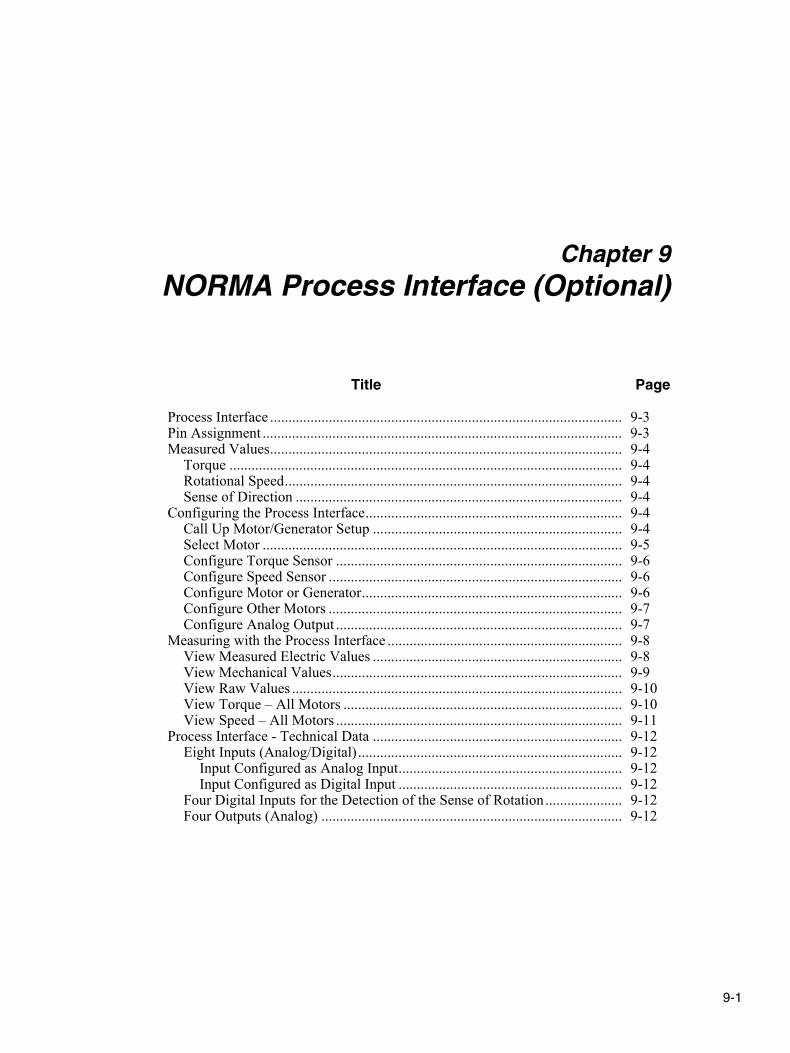
9-1
Chapter 9 NORMA Process Interface (Optional)
Title Page
Process Interface ................................................................................................ 9-3 Pin Assignment .................................................................................................. 9-3 Measured Values................................................................................................ 9-4
Torque ........................................................................................................... 9-4 Rotational Speed............................................................................................ 9-4 Sense of Direction ......................................................................................... 9-4
Configuring the Process Interface...................................................................... 9-4 Call Up Motor/Generator Setup .................................................................... 9-4 Select Motor .................................................................................................. 9-5 Configure Torque Sensor .............................................................................. 9-6 Configure Speed Sensor ................................................................................ 9-6 Configure Motor or Generator....................................................................... 9-6 Configure Other Motors ................................................................................ 9-7 Configure Analog Output .............................................................................. 9-7
Measuring with the Process Interface ................................................................ 9-8 View Measured Electric Values .................................................................... 9-8 View Mechanical Values............................................................................... 9-9 View Raw Values .......................................................................................... 9-10 View Torque – All Motors ............................................................................ 9-10 View Speed – All Motors .............................................................................. 9-11
Process Interface - Technical Data .................................................................... 9-12 Eight Inputs (Analog/Digital) ........................................................................ 9-12
Input Configured as Analog Input............................................................. 9-12 Input Configured as Digital Input ............................................................. 9-12
Four Digital Inputs for the Detection of the Sense of Rotation ..................... 9-12 Four Outputs (Analog) .................................................................................. 9-12

NORMA 4000/5000 Operators Manual
9-2
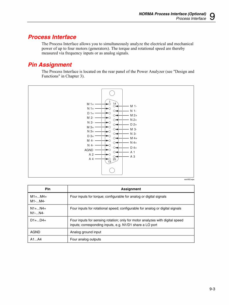
NORMA Process Interface (Optional) Process Interface 9
9-3
Process Interface The Process Interface allows you to simultaneously analyze the electrical and mechanical power of up to four motors (generators). The torque and rotational speed are thereby measured via frequency inputs or as analog signals.
Pin Assignment The Process Interface is located on the rear panel of the Power Analyzer (see "Design and Functions" in Chapter 3).
114
1325
M 1-
N 1-M 2+N 2+
D 2+
M 3-N 3-M 4+N 4+
D 4+A 1A 3
A 4A 2
AGND
N 4-
M 4-D 3+
N 3+M 3+
N 2-
M 2-D 1+
N 1+M 1+
esn063.eps
Pin Assignment
M1+...M4+ M1-...M4-
Four inputs for torque; configurable for analog or digital signals
N1+...N4+ N1-...N4-
Four inputs for rotational speed; configurable for analog or digital signals
D1+...D4+ Four inputs for sensing rotation; only for motor analyzes with digital speed inputs; corresponding inputs, e.g. N1/D1 share a LO port
AGND Analog ground input
A1...A4 Four analog outputs
NORMA 4000/5000 Operators Manual
9-4
Measured Values
Torque The torque is measured by means of a force transducer or torque measuring shaft with a ±10 V dc output or a frequency output.
Rotational Speed The speed is measured by means of an incremental encoder with TTl or AC output; alternatively, for example, an analog signal from a speedometer might be used.
Sense of Direction The sense of direction is detected by means of a permanent signal (L = sense of direction positive, H = sense of direction negative); alternatively, it might be determined using an incremental encoder. In this case, the following applies: if the signal is leading, the sense of direction is positive; if the signal is lagging, the sense of direction is negative.
Configuring the Process Interface Prior to starting the measuring process, the torque sensor and the speed sensor must be configured. To configure the Process Interface, select menu Motor/Generator Setup. The configuration procedure consists of the following steps:
• Call up Motor/Generator Setup • Select motor • Configure torque sensor • Configure speed sensor • Configure other motors • Configure analog outputs
Call Up Motor/Generator Setup • The device must be equipped with a ANALOG INTERFACE process interface • Menu item PI must be shown in the menu bar
If the Power Analyzer is equipped with a process interface, menu item PI is shown automatically in the menu.
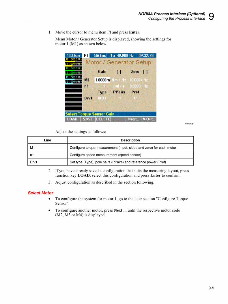
NORMA Process Interface (Optional) Configuring the Process Interface 9
9-5
1. Move the cursor to menu item PI and press Enter. Menu Motor / Generator Setup is displayed, showing the settings for motor 1 (M1) as shown below.
esn064.gif
Adjust the settings as follows:
Line Description
M1 Configure torque measurement (input, slope and zero) for each motor
n1 Configure speed measurement (speed sensor)
Drv1 Set type (Type), pole pairs (PPairs) and reference power (Pref)
2. If you have already saved a configuration that suits the measuring layout, press function key LOAD, select this configuration and press Enter to confirm.
3. Adjust configuration as described in the section following.
Select Motor • To configure the system for motor 1, go to the later section "Configure Torque
Sensor". • To configure another motor, press Next ... until the respective motor code
(M2, M3 or M4) is displayed.
NORMA 4000/5000 Operators Manual
9-6
Configure Torque Sensor The torque can be measured by means of force transducers or a torque-measuring shaft. The signal is transferred via a ±10 V AC output or a frequency output. In line M.. (for example, motor 1: M1), adjust the following settings:
Column Settings Description
Gain 1... Slope
Unit Nm/Hz Nm/V
Depending on force transducer or sensing shaft type
Zero 1... Voltage or frequency corresponding to speed = 0
Unit Hz, V Unit for zero, depending on sensor type
1. Move the cursor to a field in line M1 and press Enter. A list of possible options is displayed.
2. Select a value and press Enter to confirm. The value is now shown in the display field.
Configure Speed Sensor Possible speed sensors include the incremental encoder (measuring with TTL / AC output) or an analog signal. In line n (for example,motor 1: n1), adjust the settings as follows:
Column Settings Description
Gain 1... Slope
Unit pul/r rpm/V
Pulses per revolution Revolutions per volt
Zero 1... Voltage or frequency corresponding to speed = 0
Unit Hz, V Unit for zero, depending on sensor type
1. Move the cursor to a field in line n1 and press Enter. A list of possible options is displayed.
2. Select a value and press Enter to confirm. The value is now shown in the display field.
Configure Motor or Generator The Power Analyzer can be used for the analysis of both motors and generators. To configure the device, adjust the settings in line Drv1 for motor 1:
Column Settings Description
Type MOT GEN
Motor Generator
PPairs 1 ... 999 Number of pole pairs
Pref P ... P3 Reference power for efficiency calculation
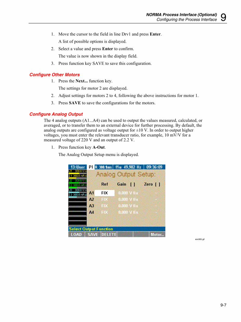
NORMA Process Interface (Optional) Configuring the Process Interface 9
9-7
1. Move the cursor to the field in line Drv1 and press Enter. A list of possible options is displayed.
2. Select a value and press Enter to confirm. The value is now shown in the display field.
3. Press function key SAVE to save this configuration.
Configure Other Motors 1. Press the Next... function key.
The settings for motor 2 are displayed. 2. Adjust settings for motors 2 to 4, following the above instructions for motor 1. 3. Press SAVE to save the configurations for the motors.
Configure Analog Output The 4 analog outputs (A1...A4) can be used to output the values measured, calculated, or averaged, or to transfer them to an external device for further processing. By default, the analog outputs are configured as voltage output for ±10 V. In order to output higher voltages, you must enter the relevant transducer ratio, for example, 10 mV/V for a measured voltage of 220 V and an output of 2.2 V.
1. Press function key A-Out. The Analog Output Setup menu is displayed.
esn065.gif
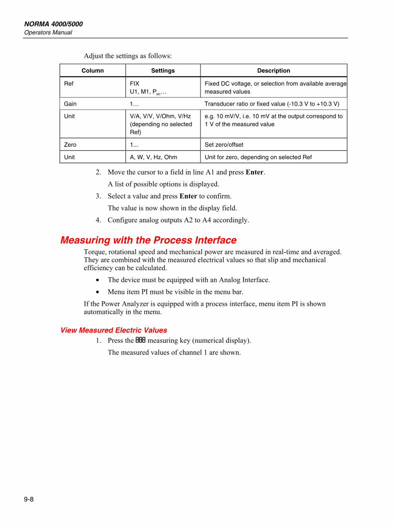
NORMA 4000/5000 Operators Manual
9-8
Adjust the settings as follows:
Column Settings Description
Ref FIX U1, M1, PM1…
Fixed DC voltage, or selection from available average measured values
Gain 1… Transducer ratio or fixed value (-10.3 V to +10.3 V)
Unit V/A, V/V, V/Ohm, V/Hz (depending no selected Ref)
e.g. 10 mV/V, i.e. 10 mV at the output correspond to 1 V of the measured value
Zero 1... Set zero/offset
Unit A, W, V, Hz, Ohm Unit for zero, depending on selected Ref
2. Move the cursor to a field in line A1 and press Enter. A list of possible options is displayed.
3. Select a value and press Enter to confirm. The value is now shown in the display field.
4. Configure analog outputs A2 to A4 accordingly.
Measuring with the Process Interface Torque, rotational speed and mechanical power are measured in real-time and averaged. They are combined with the measured electrical values so that slip and mechanical efficiency can be calculated.
• The device must be equipped with an Analog Interface. • Menu item PI must be visible in the menu bar.
If the Power Analyzer is equipped with a process interface, menu item PI is shown automatically in the menu.
View Measured Electric Values 1. Press the 888 measuring key (numerical display).
The measured values of channel 1 are shown.
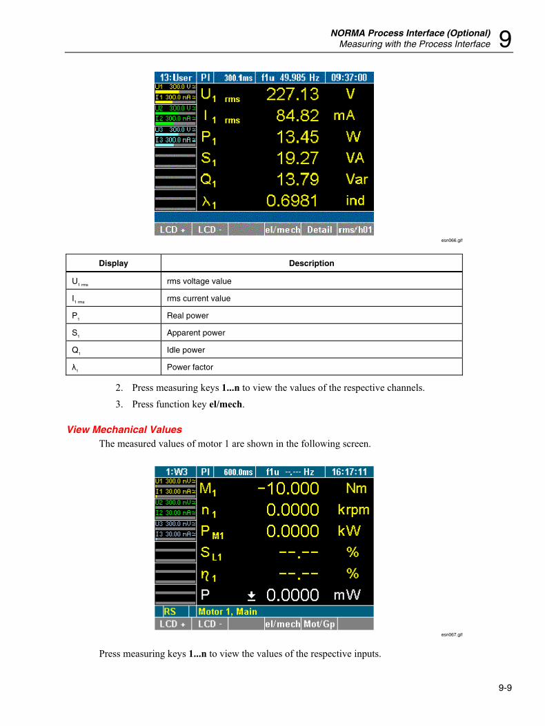
NORMA Process Interface (Optional) Measuring with the Process Interface 9
9-9
esn066.gif
Display Description
U1 rms rms voltage value
I1 rms rms current value
P1 Real power
S1 Apparent power
Q1 Idle power
λ1 Power factor
2. Press measuring keys 1...n to view the values of the respective channels. 3. Press function key el/mech.
View Mechanical Values The measured values of motor 1 are shown in the following screen.
esn067.gif
Press measuring keys 1...n to view the values of the respective inputs.
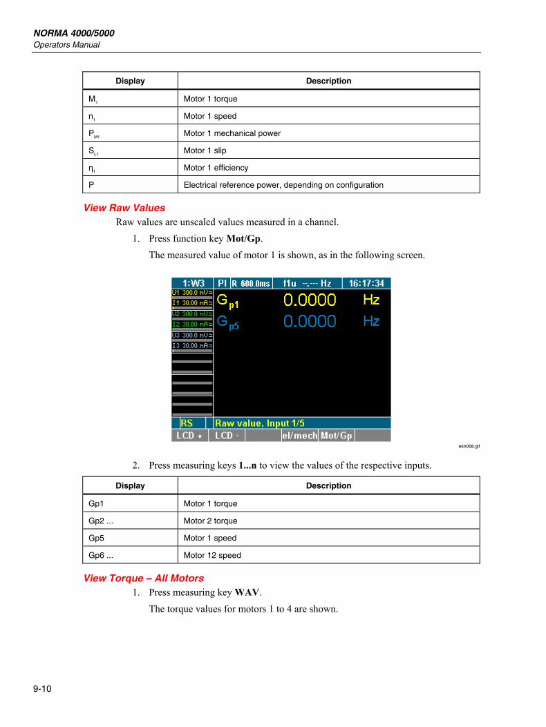
NORMA 4000/5000 Operators Manual
9-10
Display Description
M1 Motor 1 torque
n1 Motor 1 speed
PM1 Motor 1 mechanical power
SL1 Motor 1 slip
η1 Motor 1 efficiency
P Electrical reference power, depending on configuration
View Raw Values Raw values are unscaled values measured in a channel.
1. Press function key Mot/Gp. The measured value of motor 1 is shown, as in the following screen.
esn068.gif
2. Press measuring keys 1...n to view the values of the respective inputs.
Display Description
Gp1 Motor 1 torque
Gp2 ... Motor 2 torque
Gp5 Motor 1 speed
Gp6 ... Motor 12 speed
View Torque – All Motors 1. Press measuring key WAV.
The torque values for motors 1 to 4 are shown.
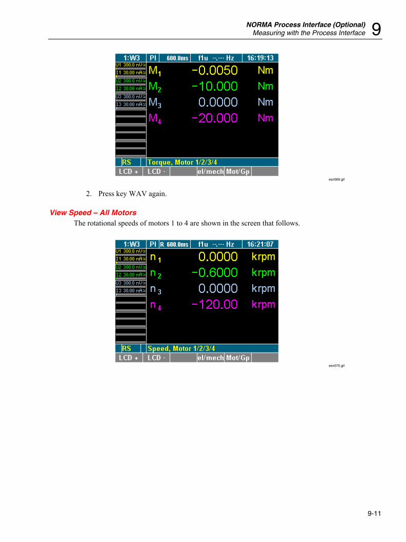
NORMA Process Interface (Optional) Measuring with the Process Interface 9
9-11
esn069.gif
2. Press key WAV again.
View Speed – All Motors The rotational speeds of motors 1 to 4 are shown in the screen that follows.
esn070.gif
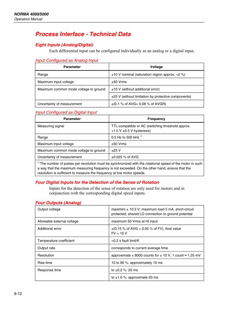
NORMA 4000/5000 Operators Manual
9-12
Process Interface - Technical Data
Eight Inputs (Analog/Digital) Each differential input can be configured individually as an analog or a digital input.
Input Configured as Analog Input
Parameter Voltage
Range ±10 V nominal (saturation region approx. +2 %)
Maximum input voltage ±50 Vrms
±10 V (without additional error) Maximum common mode voltage to ground
±25 V (without limitation by protective components)
Uncertainty of measurement ±(0.1 % of AVG+ 0.08 % of AVGR)
Input Configured as Digital Input
Parameter Frequency
Measuring signal TTL-compatible or AC (switching threshold approx. +1.5 V ±0.5 V hysteresis)
Range 0.5 Hz to 500 kHz [1]
Maximum input voltage ±50 Vrms
Maximum common mode voltage to ground ±25 V
Uncertainty of measurement ±0.025 % of AVG [1] The number of pulses per revolution must be synchronized with the rotational speed of the motor in such a way that the maximum measuring frequency is not exceeded. On the other hand, ensure that the resolution is sufficient to measure the frequency at low motor speeds.
Four Digital Inputs for the Detection of the Sense of Rotation Inputs for the detection of the sense of rotation are only used for motors and in conjunction with the corresponding digital speed inputs.
Four Outputs (Analog) Output voltage maximim ± 10.3 V; maximum load 5 mA, short-circuit
protected, shared LO connection to ground potential
Allowable external voltage maximum 50 Vrms at HI input
Additional error ±(0.15 % of AVG + 0.05 % of FV), final value FV = 10 V
Temperature coefficient <0.2 x fault limit/K
Output rate corresponds to current average time
Resolution approximate ± 8000 counts for ± 10 V, 1 count ≈ 1.25 mV
Rise time 10 to 90 %: approximately 10 ms
to ±0.2 %: 25 ms Response time
to ±1.0 %: approximate 20 ms
10-1
Chapter 10 Formulas
Title Page
Direct Current .................................................................................................... 10-3 Alternating Current ............................................................................................ 10-3 Fundamental and Harmonics ............................................................................. 10-4 Frequency Analysis............................................................................................ 10-5 Uncertainty of Measurement.............................................................................. 10-5

NORMA 4000/5000 Operators Manual
10-2
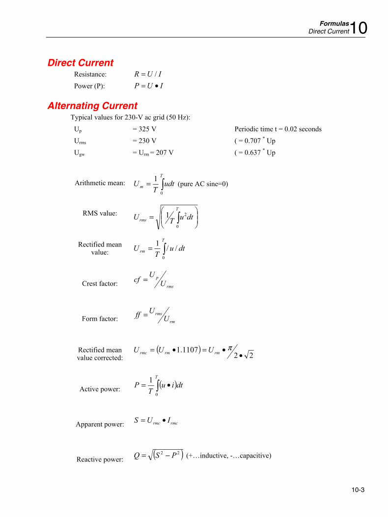
Formulas Direct Current10
10-3
Direct Current Resistance: IUR /= Power (P): IUP •=
Alternating Current Typical values for 230-V ac grid (50 Hz): Up = 325 V Periodic time t = 0.02 seconds Urms = 230 V ( = 0.707 * Up Ugw = Urm = 207 V ( = 0.637 * Up
Arithmetic mean: ∫=T
m udtT
U0
1 (pure AC sine=0)
RMS value: ⎟⎟⎠
⎞⎜⎜⎝
⎛= ∫
T
rms dtuTU0
21
Rectified mean value: ∫=
T
rm dtuT
U0
//1
Crest factor: rms
pU
Ucf =
Form factor: rm
rmsU
Uff =
Rectified mean value corrected:
( )22
1107.1•
•=•= πrmrmrmc UUU
Active power: ( )∫ •=T
dtiuT
P0
1
Apparent power: rmcrmc IUS •=
Reactive power: ( )22 PSQ −= (+…inductive, -…capacitive)
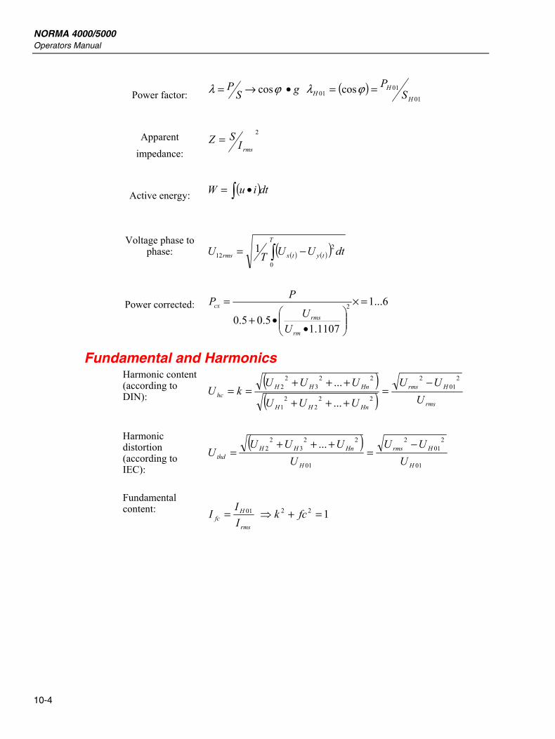
NORMA 4000/5000 Operators Manual
10-4
Power factor: gSP cos •→= ϕλ ( )
01
0101 cos
H
HH S
P== ϕλ
Apparent impedance:
2
rmsISZ =
Active energy: ( )dtiuW ∫ •=
Voltage phase to phase: ( ) ( )( )∫ −=
T
tytxrms dtUUTU0
212
1
Power corrected: 6...1
1107.15.05.0
2 =×
⎟⎟⎠
⎞⎜⎜⎝
⎛•
•+
=
rm
rms
cx
UU
PP
Fundamental and Harmonics Harmonic content (according to DIN):
( )( ) rms
Hrms
HnHH
HnHHhc U
UU
UUU
UUUkU
201
2
222
21
223
22
...
... −=
+++
+++==
Harmonic distortion (according to IEC):
( )01
201
2
01
223
22 ...
H
Hrms
H
HnHHthd U
UUU
UUUU
−=
+++=
Fundamental content:
rms
Hfc I
II 01= 122 =+⇒ fck
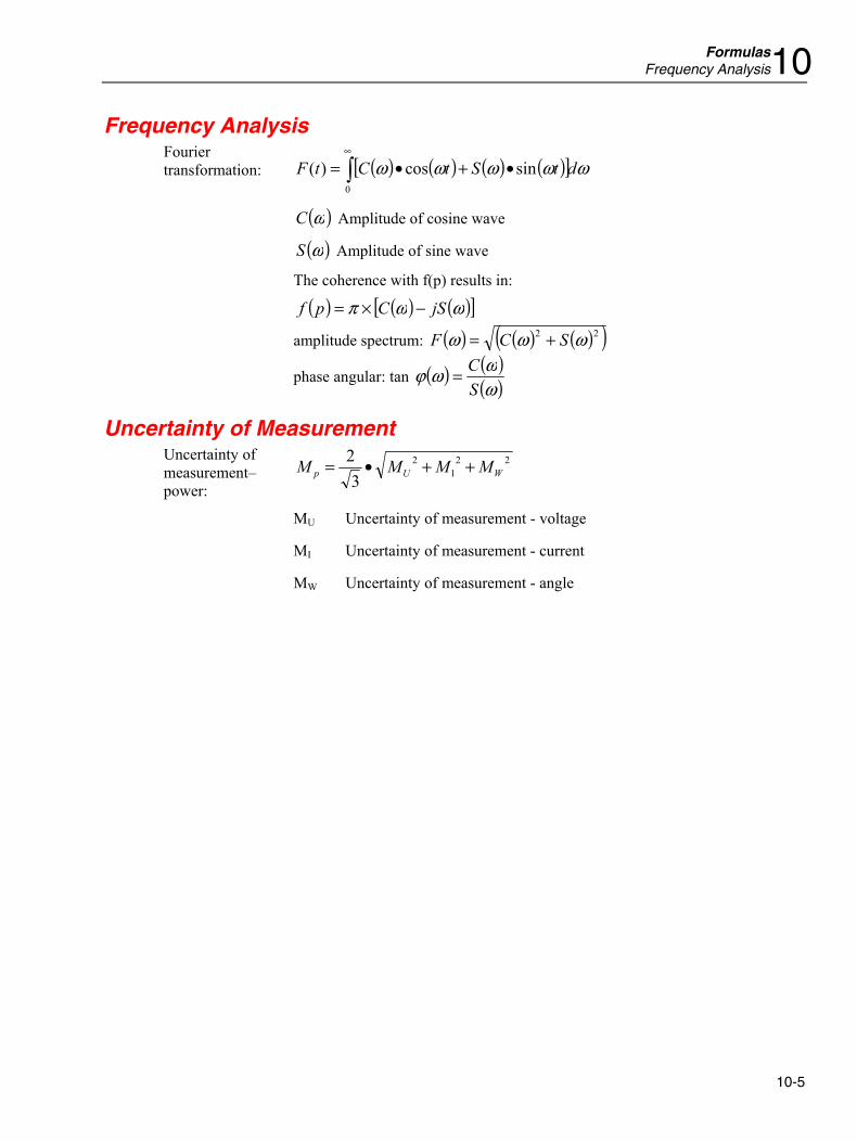
Formulas Frequency Analysis10
10-5
Frequency Analysis
( ) ( ) ( ) ( )[ ] ωωωωω dtStCtF ∫∞
•+•=0
sincos)(
( )ωC Amplitude of cosine wave
( )ωS Amplitude of sine wave
The coherence with f(p) results in:
( ) ( ) ( )[ ]ωωπ jSCpf −×=
amplitude spectrum: ( ) ( ) ( )( )22 ωωω SCF +=
Fourier transformation:
phase angular: tan ( ) ( )( )ωωωϕ
SC=
Uncertainty of Measurement 22
12
32
WUp MMMM ++•=
MU Uncertainty of measurement - voltage
MI Uncertainty of measurement - current
Uncertainty of measurement–power:
MW Uncertainty of measurement - angle

NORMA 4000/5000 Operators Manual
10-6
11-1
Chapter 11 Technical Data
Title Page
Technical Data Fluke NORMA 4000 ................................................................ 11-3 General Technical Data ................................................................................. 11-3 Ambient Conditions....................................................................................... 11-3 Specifications ................................................................................................ 11-4
Voltage ...................................................................................................... 11-4 Current ...................................................................................................... 11-4 Frequency Angle ....................................................................................... 11-5 Frequency and Synchronization ................................................................ 11-5 Data Memory ............................................................................................ 11-5 Configuration Memory.............................................................................. 11-5 Interfaces ................................................................................................... 11-6 Standards ................................................................................................... 11-6
Technical Data Fluke NORMA 5000 ................................................................ 11-7 General Technical Data ................................................................................. 11-7 Ambient Conditions....................................................................................... 11-7 Specifications ................................................................................................ 11-8
Voltage ...................................................................................................... 11-8 Current ...................................................................................................... 11-8 Frequency Angle ....................................................................................... 11-9 Frequency and Synchronization ................................................................ 11-9 Data Memory ............................................................................................ 11-9 Configuration Memory.............................................................................. 11-9 Interfaces ................................................................................................... 11-10 Standards ................................................................................................... 11-10
Block Diagrams ................................................................................................. 11-11 Overview ....................................................................................................... 11-11 Voltage Channels........................................................................................... 11-12 Current Channels ........................................................................................... 11-12

NORMA 4000/5000 Operators Manual
11-2
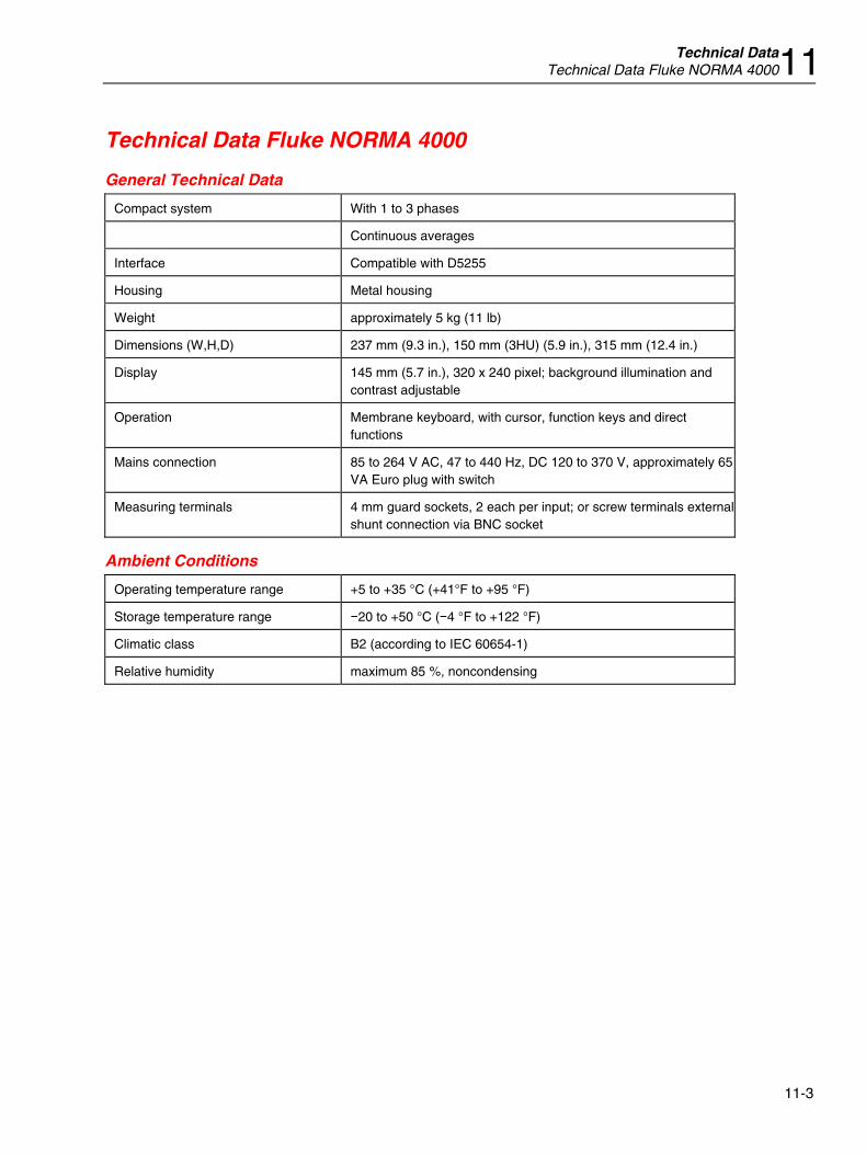
Technical Data Technical Data Fluke NORMA 400011
11-3
Technical Data Fluke NORMA 4000
General Technical Data
Compact system With 1 to 3 phases
Continuous averages
Interface Compatible with D5255
Housing Metal housing
Weight approximately 5 kg (11 lb)
Dimensions (W,H,D) 237 mm (9.3 in.), 150 mm (3HU) (5.9 in.), 315 mm (12.4 in.)
Display 145 mm (5.7 in.), 320 x 240 pixel; background illumination and contrast adjustable
Operation Membrane keyboard, with cursor, function keys and direct functions
Mains connection 85 to 264 V AC, 47 to 440 Hz, DC 120 to 370 V, approximately 65VA Euro plug with switch
Measuring terminals 4 mm guard sockets, 2 each per input; or screw terminals external shunt connection via BNC socket
Ambient Conditions
Operating temperature range +5 to +35 °C (+41°F to +95 °F)
Storage temperature range −20 to +50 °C (−4 °F to +122 °F)
Climatic class B2 (according to IEC 60654-1)
Relative humidity maximum 85 %, noncondensing
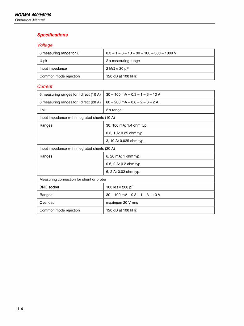
NORMA 4000/5000 Operators Manual
11-4
Specifications
Voltage
8 measuring range for U 0.3 – 1 – 3 – 10 – 30 – 100 – 300 – 1000 V
U pk 2 x measuring range
Input impedance 2 MΩ // 20 pF
Common mode rejection 120 dB at 100 kHz
Current
6 measuring ranges for I direct (10 A) 30 – 100 mA – 0.3 – 1 – 3 – 10 A
6 measuring ranges for I direct (20 A) 60 – 200 mA – 0.6 – 2 – 6 – 2 A
I pk 2 x range
Input impedance with integrated shunts (10 A)
30, 100 mA: 1.4 ohm typ.
0.3, 1 A: 0.25 ohm typ.
Ranges
3, 10 A: 0.025 ohm typ.
Input impedance with integrated shunts (20 A)
6, 20 mA: 1 ohm typ.
0.6, 2 A: 0.2 ohm typ
Ranges
6, 2 A: 0.02 ohm typ.
Measuring connection for shunt or probe
BNC socket 100 kΩ // 200 pF
Ranges 30 – 100 mV – 0.3 – 1 – 3 – 10 V
Overload maximum 20 V rms
Common mode rejection 120 dB at 100 kHz
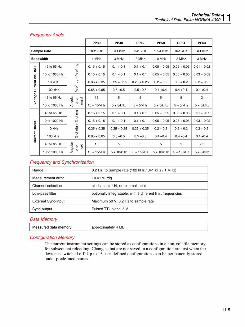
Technical Data Technical Data Fluke NORMA 400011
11-5
Frequency Angle
PP30 PP40 PP42 PP50 PP54 PP64
Sample Rate 102 kHz 341 kHz 341 kHz 1024 kHz 341 kHz 341 kHz
Bandwidth 1 MHz 3 MHz 3 MHz 10 MHz 3 MHz 3 MHz
45 to 65 Hz 0.15 + 0.15 0.1 + 0.1 0.1 + 0.1 0.05 + 0.05 0.05 + 0.05 0.01 + 0.02
10 to 1000 Hz 0.15 + 0.15 0.1 + 0.1 0.1 + 0.1 0.05 + 0.05 0.05 + 0.05 0.03 + 0.02
10 kHz 0.35 + 0.35 0.25 + 0.25 0.25 + 0.25 0.2 + 0.2 0.2 + 0.2 0.2 + 0.2
100 kHz % o
f rdg
+ %
of r
ng
0.65 + 0.65 0.5 +0.5 0.5 +0.5 0.4 +0.4 0.4 +0.4 0.4 +0.4
45 to 65 Hz 15 5 5 5 5 2
Vo
ltag
e C
urr
ent
via
BN
C
10 to 1000 Hz Ang
ular
erro
r
mgr
d
15 + 15/kHz 5 + 5/kHz 5 + 5/kHz 5 + 5/kHz 5 + 5/kHz 5 + 5/kHz
45 to 65 Hz 0.15 + 0.15 0.1 + 0.1 0.1 + 0.1 0.05 + 0.05 0.05 + 0.05 0.01 + 0.02
10 to 1000 Hz 0.15 + 0.15 0.1 + 0.1 0.1 + 0.1 0.05 + 0.05 0.05 + 0.05 0.03 + 0.02
10 kHz 0.35 + 0.35 0.25 + 0.25 0.25 + 0.25 0.2 + 0.2 0.2 + 0.2 0.2 + 0.2
100 kHz % o
f rdg
+ %
of r
ng
0.65 + 0.65 0.5 +0.5 0.5 +0.5 0.4 +0.4 0.4 +0.4 0.4 +0.4
45 to 65 Hz 15 5 5 5 5 2.5
Cu
rren
t D
irec
t
10 to 1000 Hz Ang
ular
erro
r
mgr
d
15 + 15/kHz 5 + 10/kHz 5 + 15/kHz 5 + 10/kHz 5 + 10/kHz 5 + 5/kHz
Frequency and Synchronization
Range 0.2 Hz to Sample rate (102 kHz / 341 kHz / 1 MHz)
Measurement error ±0.01 % rdg
Channel selection all channels U/I, or external input
Low-pass filter optionally integratable, with 3 different limit frequencies
External Sync-input Maximum 50 V, 0,2 Hz to sample rate
Sync-output Pulsed TTL signal 5 V
Data Memory
Measured data memory approximately 4 MB
Configuration Memory The current instrument settings can be stored as configurations in a non-volatile memory for subsequent reloading. Changes that are not saved in a configuration are lost when the device is switched off. Up to 15 user-defined configurations can be permanently stored under predefined names.
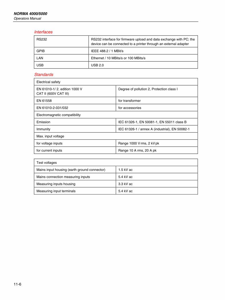
NORMA 4000/5000 Operators Manual
11-6
Interfaces
RS232 RS232 interface for firmware upload and data exchange with PC; the device can be connected to a printer through an external adapter
GPIB IEEE 488.2 / 1 MBit/s
LAN Ethernet / 10 MBits/s or 100 MBits/s
USB USB 2.0
Standards
Electrical safety
EN 61010-1/ 2. edition 1000 V CAT II (600V CAT III)
Degree of pollution 2, Protection class I
EN 61558 for transformer
EN 61010-2-031/032 for accessories
Electromagnetic compatibility
Emission IEC 61326-1, EN 50081-1, EN 55011 class B
Immunity IEC 61326-1 / annex A (industrial), EN 50082-1
Max. input voltage
for voltage inputs Range 1000 V rms, 2 kV pk
for current inputs Range 10 A rms, 20 A pk
Test voltages
Mains input housing (earth ground connector) 1.5 kV ac
Mains connection measuring inputs 5.4 kV ac
Measuring inputs housing 3.3 kV ac
Measuring input terminals 5.4 kV ac
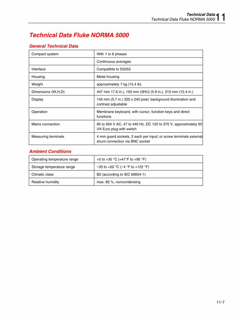
Technical Data Technical Data Fluke NORMA 500011
11-7
Technical Data Fluke NORMA 5000
General Technical Data
Compact system With 1 to 6 phases
Continuous averages
Interface Compatible to D5255
Housing Metal housing
Weight approximately 7 kg (15.4 lb)
Dimensions (W,H,D) 447 mm 17.6 in.), 150 mm (3HU) (5.9 in.), 315 mm (12.4 in.)
Display 145 mm (5.7 in.) 320 x 240 pixel; background illumination and contrast adjustable
Operation Membrane keyboard, with cursor, function keys and direct functions
Mains connection 85 to 264 V AC, 47 to 440 Hz, DC 120 to 370 V, approximately 65VA Euro plug with switch
Measuring terminals 4 mm guard sockets, 2 each per input; or screw terminals external shunt connection via BNC socket
Ambient Conditions
Operating temperature range +5 to +35 °C (+41°F to +95 °F)
Storage temperature range −20 to +50 °C (−4 °F to +122 °F)
Climatic class B2 (according to IEC 60654-1)
Relative humidity max. 85 %, noncondensing
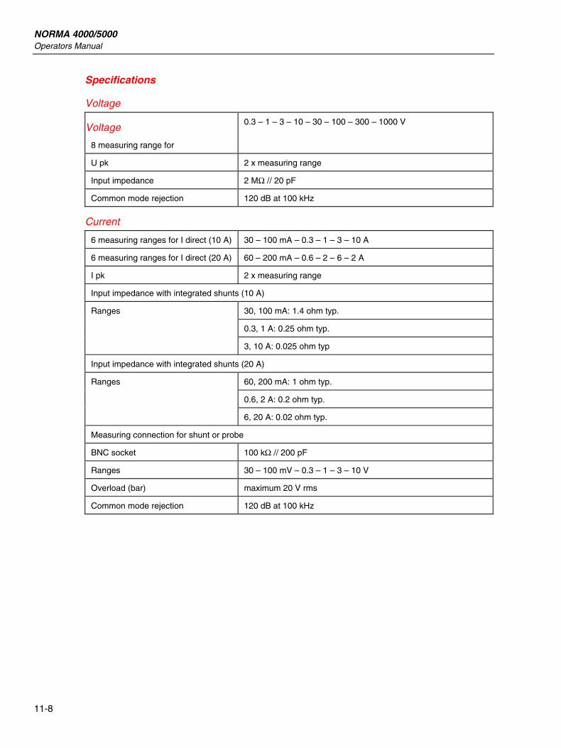
NORMA 4000/5000 Operators Manual
11-8
Specifications
Voltage
Voltage
8 measuring range for
0.3 – 1 – 3 – 10 – 30 – 100 – 300 – 1000 V
U pk 2 x measuring range
Input impedance 2 MΩ // 20 pF
Common mode rejection 120 dB at 100 kHz
Current
6 measuring ranges for I direct (10 A) 30 – 100 mA – 0.3 – 1 – 3 – 10 A
6 measuring ranges for I direct (20 A) 60 – 200 mA – 0.6 – 2 – 6 – 2 A
I pk 2 x measuring range
Input impedance with integrated shunts (10 A)
30, 100 mA: 1.4 ohm typ.
0.3, 1 A: 0.25 ohm typ.
Ranges
3, 10 A: 0.025 ohm typ
Input impedance with integrated shunts (20 A)
60, 200 mA: 1 ohm typ.
0.6, 2 A: 0.2 ohm typ.
Ranges
6, 20 A: 0.02 ohm typ.
Measuring connection for shunt or probe
BNC socket 100 kΩ // 200 pF
Ranges 30 – 100 mV – 0.3 – 1 – 3 – 10 V
Overload (bar) maximum 20 V rms
Common mode rejection 120 dB at 100 kHz

Technical Data Technical Data Fluke NORMA 500011
11-9
Frequency Angle
PP30 PP40 PP42 PP50 PP54 PP64
Sample Rate 102 kHz 341 kHz 341 kHz 1024 kHz 341 kHz 341 kHz
Bandwidth 1 MHz 3 MHz 3 MHz 10 MHz 3 MHz 3 MHz
45 to 65 Hz 0.15 + 0.15 0.1 + 0.1 0.1 + 0.1 0.05 + 0.05 0.05 + 0.05 0.01 + 0.02
10 to 1000 Hz 0.15 + 0.15 0.1 + 0.1 0.1 + 0.1 0.05 + 0.05 0.05 + 0.05 0.03 + 0.02
10 kHz 0.35 + 0.35 0.25 + 0.25 0.25 + 0.25 0.2 + 0.2 0.2 + 0.2 0.2 + 0.2
100 kHz % o
f rdg
+ %
of r
ng
0.65 + 0.65 0.5 +0.5 0.5 +0.5 0.4 +0.4 0.4 +0.4 0.4 +0.4
45 to 65 Hz 15 5 5 5 5 2
Vo
ltag
e C
urr
ent
via
BN
C
10 to 1000 Hz Ang
ular
erro
r
mgr
d
15 + 15/kHz 5 + 5/kHz 5 + 5/kHz 5 + 5/kHz 5 + 5/kHz 5 + 5/kHz
45 to 65 Hz 0.15 + 0.15 0.1 + 0.1 0.1 + 0.1 0.05 + 0.05 0.05 + 0.05 0.01 + 0.02
10 to 1000 Hz 0.15 + 0.15 0.1 + 0.1 0.1 + 0.1 0.05 + 0.05 0.05 + 0.05 0.03 + 0.02
10 kHz 0.35 + 0.35 0.25 + 0.25 0.25 + 0.25 0.2 + 0.2 0.2 + 0.2 0.2 + 0.2
100 kHz % o
f rdg
+ %
of r
ng
0.65 + 0.65 0.5 +0.5 0.5 +0.5 0.4 +0.4 0.4 +0.4 0.4 +0.4
45 to 65 Hz 15 5 5 5 5 2.5
Cu
rren
t D
irec
t
10 to 1000 Hz Ang
ular
erro
r
mgr
d
15 + 15/kHz 5 + 10/kHz 5 + 15/kHz 5 + 10/kHz 5 + 10/kHz 5 + 5/kHz
Frequency and Synchronization
Range 0.2 Hz ... Sample rate (102 kHz / 341 kHz / 1 MHz)
Measurement error ±0.01 % rdg
Channel selection all channels U/I, or external input
Low-pass filter optionally integratable, with 3 different limit frequencies
External Sync-input Max. 50 V, 0.2 Hz to sample rate
Sync-output Pulsed TTL signal 5 V
Data Memory
Measured data memory approximately 4 MB
Configuration Memory The current instrument settings can be stored as configurations in a non-volatile memory for subsequent reloading. Changes that are not saved in a configuration are lost when the device is switched off. Up to 15 user-defined configurations can be permanently stored under predefined names.
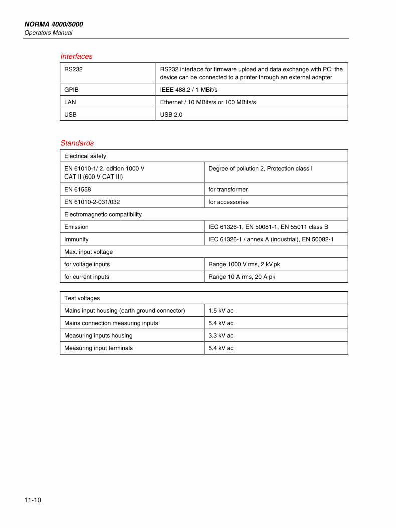
NORMA 4000/5000 Operators Manual
11-10
Interfaces
RS232 RS232 interface for firmware upload and data exchange with PC; the device can be connected to a printer through an external adapter
GPIB IEEE 488.2 / 1 MBit/s
LAN Ethernet / 10 MBits/s or 100 MBits/s
USB USB 2.0
Standards
Electrical safety
EN 61010-1/ 2. edition 1000 V CAT II (600 V CAT III)
Degree of pollution 2, Protection class I
EN 61558 for transformer
EN 61010-2-031/032 for accessories
Electromagnetic compatibility
Emission IEC 61326-1, EN 50081-1, EN 55011 class B
Immunity IEC 61326-1 / annex A (industrial), EN 50082-1
Max. input voltage
for voltage inputs Range 1000 V rms, 2 kV pk
for current inputs Range 10 A rms, 20 A pk
Test voltages
Mains input housing (earth ground connector) 1.5 kV ac
Mains connection measuring inputs 5.4 kV ac
Measuring inputs housing 3.3 kV ac
Measuring input terminals 5.4 kV ac
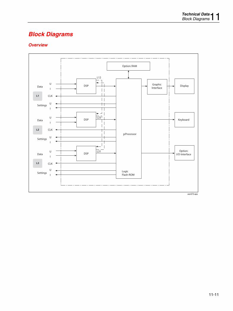
Technical Data Block Diagrams11
11-11
Block Diagrams
Overview
DSP
LogicFlash-ROM
Processor
Option: RAM
GraphicInterface
Display
Keyboard
Option:I/O-Interface
L31
L23
L12
DSP
DSPU
Data
Settings
Data
Settings
Data
Settings
CLK
I
U
CLK
I
U
CLK
I
U
I
U
I
U
I
esn073.eps
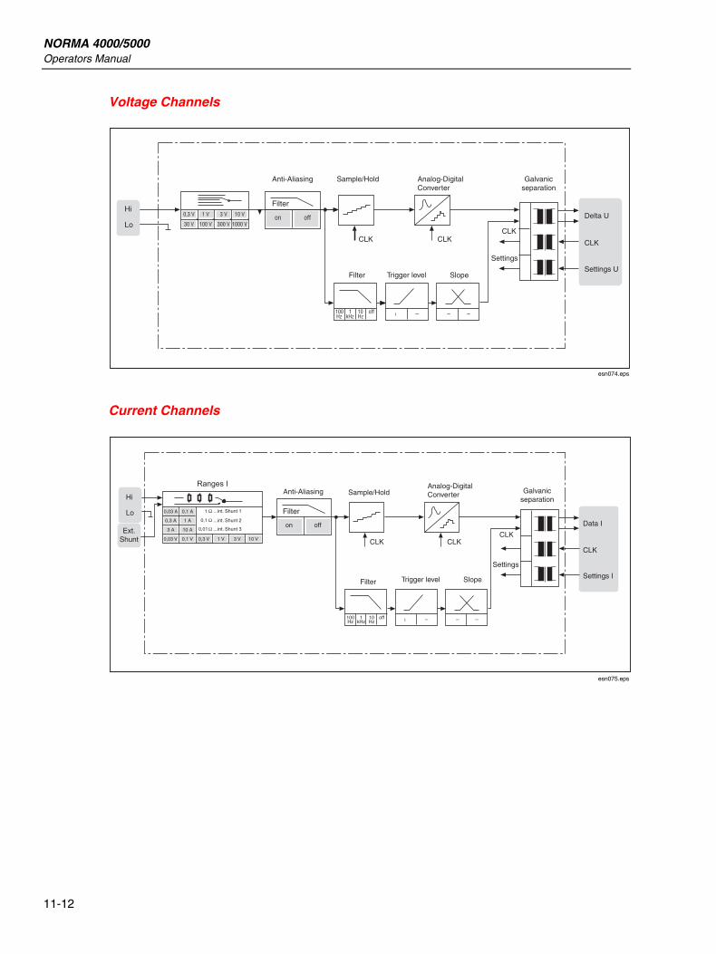
NORMA 4000/5000 Operators Manual
11-12
Voltage Channels
Anti-Aliasing
Hi
LoDelta U
Settings U
CLK
Sample/Hold
CLK CLK
SlopeFilter
100Hz
0,3 V
30 V
1 V
100 V
10 V
1000 Von
Filter
off3 V
300 V
10Hz
off1kHz
Trigger level
CLK
Settings
Analog-DigitalConverter
Galvanicseparation
esn074.eps
Current Channels
Anti-AliasingHi
Lo
Ext.Shunt
Data I
Settings I
CLK
Sample/Hold
CLK CLKCLK
SlopeFilter
100Hz
0,03 V 0,1 V 0,3 V
0,01
0,1
1
...int. Shunt 3
...int. Shunt 2
...int. Shunt 1
1 V 3 V 10 V
on
Filter
off3 A 10 A
0,3 A 1 A
0,03 A 0,1 A
10Hz
off1kHz
Trigger level
Settings
Analog-DigitalConverter Galvanic
separation
esn075.eps
12-1
Chapter 12 Service and Accessories
Title Page
Instrument .......................................................................................................... 12-3 Analyzer ........................................................................................................ 12-3 Optional Equipment....................................................................................... 12-3
Accessories ........................................................................................................ 12-4 Accessories .................................................................................................... 12-4 Software......................................................................................................... 12-4
Service ............................................................................................................... 12-4 General .......................................................................................................... 12-4

NORMA 4000/5000 Operators Manual
12-2
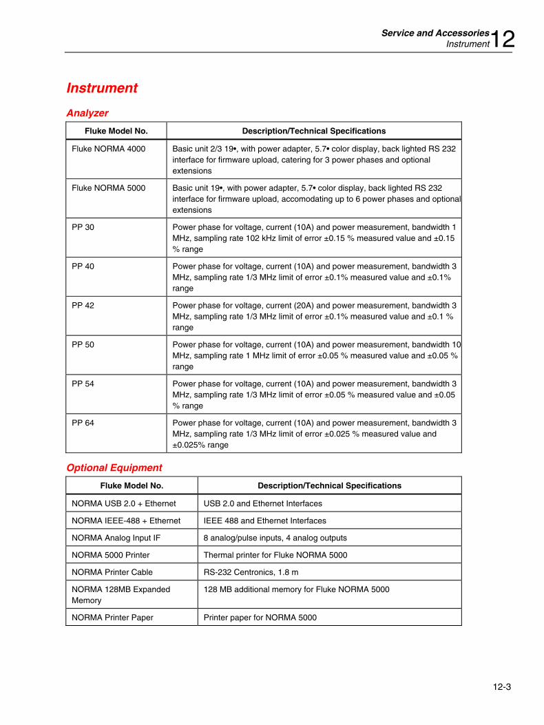
Service and Accessories Instrument12
12-3
Instrument
Analyzer
Fluke Model No. Description/Technical Specifications
Fluke NORMA 4000 Basic unit 2/3 19•, with power adapter, 5.7• color display, back lighted RS 232 interface for firmware upload, catering for 3 power phases and optional extensions
Fluke NORMA 5000 Basic unit 19•, with power adapter, 5.7• color display, back lighted RS 232 interface for firmware upload, accomodating up to 6 power phases and optional extensions
PP 30 Power phase for voltage, current (10A) and power measurement, bandwidth 1 MHz, sampling rate 102 kHz limit of error ±0.15 % measured value and ±0.15 % range
PP 40 Power phase for voltage, current (10A) and power measurement, bandwidth 3 MHz, sampling rate 1/3 MHz limit of error ±0.1% measured value and ±0.1% range
PP 42 Power phase for voltage, current (20A) and power measurement, bandwidth 3 MHz, sampling rate 1/3 MHz limit of error ±0.1% measured value and ±0.1 % range
PP 50 Power phase for voltage, current (10A) and power measurement, bandwidth 10 MHz, sampling rate 1 MHz limit of error ±0.05 % measured value and ±0.05 % range
PP 54 Power phase for voltage, current (10A) and power measurement, bandwidth 3 MHz, sampling rate 1/3 MHz limit of error ±0.05 % measured value and ±0.05 % range
PP 64 Power phase for voltage, current (10A) and power measurement, bandwidth 3 MHz, sampling rate 1/3 MHz limit of error ±0.025 % measured value and ±0.025% range
Optional Equipment
Fluke Model No. Description/Technical Specifications
NORMA USB 2.0 + Ethernet USB 2.0 and Ethernet Interfaces
NORMA IEEE-488 + Ethernet IEEE 488 and Ethernet Interfaces
NORMA Analog Input IF 8 analog/pulse inputs, 4 analog outputs
NORMA 5000 Printer Thermal printer for Fluke NORMA 5000
NORMA Printer Cable RS-232 Centronics, 1.8 m
NORMA 128MB Expanded Memory
128 MB additional memory for Fluke NORMA 5000
NORMA Printer Paper Printer paper for NORMA 5000
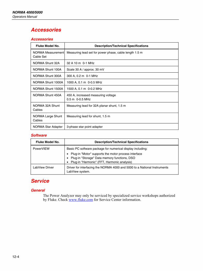
NORMA 4000/5000 Operators Manual
12-4
Accessories
Accessories
Fluke Model No. Description/Technical Specifications
NORMA Measurement Cable Set
Measuring lead set for power phase, cable length 1.5 m
NORMA Shunt 32A 32 A 10 m 0-1 MHz
NORMA Shunt 100A Scale 30 A / approx. 30 mV
NORMA Shunt 300A 300 A, 0.2 m 0-1 MHz
NORMA Shunt 1000A 1000 A, 0.1 m 0-0.5 MHz
NORMA Shunt 1500A 1500 A, 0.1 m 0-0.2 MHz
NORMA Shunt 450A 450 A, increased measuring voltage 0.5 m 0-0.5 MHz
NORMA 32A Shunt Cables
Measuring lead for 32A planar shunt, 1.5 m
NORMA Large Shunt Cables
Measuring lead for shunt, 1.5 m
NORMA Star Adapter 3-phase star point adapter
Software
Fluke Model No. Description/Technical Specifications
PowerVIEW Basic PC software package for numerical display including:
• Plug-in "Motor" supports the motor process interface • Plug-in "Storage" Data memory functions, DSO • Plug-in "Harmonic" (FFT, Harmonic analysis)
LabView Driver Driver for interfacing the NORMA 4000 and 5000 to a National Instruments LabView system.
Service
General The Power Analyzer may only be serviced by specialized service workshops authorized by Fluke. Check www.fluke.com for Service Center information.