norguard self-retracting lifelines instruction manual srl... · norguard self-retracting lifelines...
TRANSCRIPT

Norguard Self-Retracting Lifelines
Instruction Manual
Do not throw away these instructions!Read and understand these instructions before using equipment!
Form No. QD 154 March-13. Rev (0)

1
Table of Contents
Introduction 1
Applicable Safety Standards 2
Worker Classi�cations 2
Safety Information 2-4
Product Speci�c Applications 5-6
Limitations 6-7
Components and Speci�cations 8-9
Maintenance, Cleaning, and Storage 4
Inspection 5
Installation and Use 10-11
Inspection Log 17
Notes 17
Introduction
Thank you for purchasing a Norguard Self-Retracting Lifeline (SRL). This manual must be read andunderstood in its entirety, and used as part of an employee training program as required by CSA orany applicable provincial agency.
This and any other included instructions must be made available to the user of the equipment. Theuser must understand how to safely and e�ectively use the SRL, and all fall safety equipment used incombination with the SRL.
User Information
Date of �rst use:
Serial #:
Trainer:
User:
Labels 13-16
Recerti�cation 12
N
orgu
ard
580
Not
re D
ame
Ave.
Uni
t 16,
Sud
bury
, Ont
ario
, Can
ada,
P3C
5L2
pho
ne: (
800)
267
-685
5
ww
w.n
orgu
ard.
com

2
Applicable Safety Standards
When used according to instruction speci�cations, this product meets or exceeds all applicableCSA Z259.2.2-1998, OSHA 1926 Subpart M, OSHA 1910, ANSI Z359.14-2012, and ANSI A10.32-2012standards for fall protection. Applicable standards and regulations depend on the type of work beingdone, and also might include provincial regulations if applicable. Consult regulatory agencies for moreinformation on personal fall arrest systems and associated components.
Worker Classi�cations
! CAUTION Understand the following de�nitions of those whowork near or who may be exposed to fall hazards.
Quali�ed Person: A person with an accredited degree or certi�cation, and with extensive experienceor su�cient professional standing, who is considered pro�cient in planning and reviewing theconformity of fall protection and rescue systems.
Competent Person: A highly trained and experienced person who is ASSIGNED BY THE EMPLOYER tobe responsible for all elements of a fall safety program, including, but not limited to, its regulation,management, and application. A person who is pro�cient in identifying existing and predictablefall hazards, and who has the authority to stop work in order to eliminate hazards.
Authorized Person: A person who is assigned by their employer to work around or be subject topotential or existing fall hazards.
It is the responsibility of a Quali�ed or Competent person to supervise the job site and ensureall applicable safety regulations are complied with.
Safety Information
Do not alter equipment.
Do not misuse equipment.
Workplace conditions, including, but not limited to, �ame, corrosive chemicals, electrical shock,sharp objects, machinery, abrasive substances, weather conditions, and uneven surfaces, must beassessed by a Competent Person before fall protection equipment is selected.
The failure to understand and comply with safety regulations may result inserious injury or death. The regulations included herein are not all-inclusive,
are for reference only, and are not intended to replace a CompetentPerson’s judgement or knowledge of federal or provincial standards.
! WARNING
N
orgu
ard
580
Not
re D
ame
Ave.
Uni
t 16,
Sud
bury
, Ont
ario
, Can
ada,
P3C
5L2
pho
ne: (
800)
267
-685
5
ww
w.n
orgu
ard.
com

3
The analysis of the workplace must anticipate where workers will be performing their duties, theroutes they will take to reach their work, and the potential and existing fall hazards they may beexposed to.
Fall protection equipment must be chosen by a Competent Person. Selections must account for allpotential hazardous workplace conditions.
All fall protection equipment should be purchased new and in an unused condition.
Fall protection systems must be selected and installed under the supervision of a Competent Person,and used in a compliant manner.
Fall protection systems must be designed in a manner compliant with all federal, provincial, andsafety regulations.
Unless explicitly stated otherwise, the maximum allowable free fall distance for lanyards must notexceed 6’ (1.8m). No free fall allowed for non-LE SRLs. SRLs must arrest falls within 54” (137.1cm).
Forces applied to anchors must be calculated by a Competent Person.
Harnesses and connectors selected must be compliant with manufacturer’s instructions, and mustbe of compatible size and con�guration.
A pre-planned rescue procedure in the case of a fall is required. The rescue plan must be project-speci�c. The rescue plan must allow for employees to rescue themselves, or provide an alternativemeans for their prompt rescue.
Store rescue equipment in an easily accessible and clearly marked area.
Training of Authorized Persons to correctly erect, disassemble, inspect, maintain, store, and useequipment must be provided by a Competent Person.
Training must include the ability to recognize fall hazards, minimize the likelihood of fall hazards,and the correct use of personal fall arrest systems.
NEVER use fall protection equipment of any kind to hang, lift, support, or hoist tools or equipment,unless explicitly certi�ed for such use.
SRLs not suitable for use with aerial lifts.
Maintenance of equipment must be done according to manufacturer’s instructions. Equipmentinstructions must be retained for reference.
Prior to EACH use, all equipment in a fall protection system must be inspected for any potential orexisting de�ciencies that may result in its failure or reduced functionality. IMMEDIATELY removeequipment from service if any de�ciencies are found.
N
orgu
ard
580
Not
re D
ame
Ave.
Uni
t 16,
Sud
bury
, Ont
ario
, Can
ada,
P3C
5L2
pho
ne: (
800)
267
-685
5
ww
w.n
orgu
ard.
com

4
Equipment must be inspected by a Quali�ed Person at least every six months. SRLs must beinspected by a Competent Person at least monthly. These inspections must be documented inequipment instruction manual and on equipment inspection grid label.
Equipment must be inspected for defects, including, but not limited to, the absence of required labelsor markings, improper form/�t/function, evidence of cracks, sharp edges, deformation, corrosion,excessive heating, alteration, excessive wear, fraying, knotting, abrasion, and absence of parts.
Equipment that fails inspection in any way must immediately be removed from use, or repaired byan entity approved by the manufacturer.
No on-site repair of equipment unless explicitly permitted by Norguard.
Equipment subjected to forces of fall arrest must immediately be removed from use.
Snap hooks, carabiners, and other connectors must be selected and applied in a compatible fashion.All risk of disengagement must be eliminated. All snap hooks and carabiners must be self-lockingand self-closing, and must never be connected to each other.
Age, �tness, and health conditions can seriously a�ect the worker should a fall occur. Consult adoctor if there is any reason to doubt a user’s ability to withstand and safely absorb fall arrest forcesor perform set-up of equipment. Pregnant women and minors must not use this equipment.
Physical harm may still occur even if fall safety equipment functions correctly. Sustained post-fallsuspension may result in serious injury or death. Use trauma relief straps to reduce the e�ects ofsuspension trauma.
Allowable individual worker weight limit (including all equipment), unless explicitly statedotherwise, is 130-310 lbs (59-140.6 kg).
Maintenance, Cleaning, and Storage
Repairs to SRLs can only be made by a Norguard representative or an entity authorized by Norguard.Contact Norguard for all maintenance and repair needs at: 1-800-267-6855. If a SRL fails inspection inany way, immediately remove it from service, and contact Norguard to inquire about its return orrepair.
Cleaning after use is important for maintaining the safety and longevity of SRLs. Remove all dirt,corrosives, and contaminants from SRLs before and after each use. If equipment cannot be cleanedwith plain water, use mild soap and water, then rinse and wipe dry. NEVER clean SRLs with corrosivesubstances.
When not in use, store equipment where it will not be a�ected by heat, light, excessive moisture,chemicals, or other degrading elements. NEVER store with any lifeline played out.
N
orgu
ard
580
Not
re D
ame
Ave.
Uni
t 16,
Sud
bury
, Ont
ario
, Can
ada,
P3C
5L2
pho
ne: (
800)
267
-685
5
ww
w.n
orgu
ard.
com

5
KEEP INSTRUCTIONS AVAILABLE FOR REFERENCE. Record date of �rst use.
Prior to EACH use, inspect SRLs for de�ciencies, including, but not limited to, corrosion, deformation,pits, burrs, rough surfaces, sharp edges, cracking, rust, paint buildup, excessive heating, alteration,broken stitching, fraying, bird-caging, and missing or illegible labels. Inspect full length of cable.
Prior to EACH use, check lifeline retraction by pulling out a minimum 4’ (1.2m) and allowing it toretract under light tension; lifeline must retract completely. Pull lifeline sharply to test brakingfunction; brakes must engage. Check shock pack for signs of deployment, and/or fall arrest indicatorfor signs of activation. IMMEDIATELY remove from service if equipment does not function properly, or ifevidence exists of exposure to forces of fall arrest. For SRLs with rescue functionality, ensure winchhandle demonstrates full range of movement, and can be fully locked in place until needed. Ensurewinch can fully retract and release lifeline. IMMEDIATELY remove SRL from service if defects or damageare found.
Ensure that applicable work area is free of all damage, including, but not limited to, debris, rot, rust,decay, cracking, and hazardous materials. Ensure that selected work area will support the application-speci�c minimum loads set forth in this instruction manual. Work area MUST be stable.
EVERY month, a Competent Person other than the user must inspect SRLs. Competent Personinspections MUST be recorded in inspection log in instruction manual and on equipmentinspection grid label. The Competent Person must sign their initials in the box correspondingto the month and year the inspection took place.
During inspection, consider all applications and hazards SRLs have been subjected to.
Product Speci�c Applications
Inspection
! WARNING Use of equipment in unintended applications may result in seriousinjury or death. Maximum 1 attachment per connection point.
Personal Fall Arrest: Depending on product-speci�c con�guration, a SRL may be used in FallArrest applications to support a MAXIMUM 1 Personal Fall Arrest System (PFAS). Structure mustwithstand loads applied in the directions permitted by the system of at least 5,000 pounds(2,267.9kg). Maximum free fall is 2‘ (.6m) for SRLs certi�ed for use on a Leading Edge (LE). Nofree fall permitted when used with non-LE SRLs. For LE use, SRL must employ either an integralshock absorber or extension shock absorber. Applicable D-ring: Dorsal.
Restraint: Depending on product-speci�c con�guration, SRLs may be used in Restraintapplications to support a MAXIMUM 1 PFAS. Restraint systems prevent workers from reachingthe leading edge of a fall hazard. Always account for fully deployed length of SRL. Structuremust withstand loads applied in the directions permitted by the system of at least 1,000pounds (453.5kg). No free fall is permitted. Restraint systems may only be used on surfaceswith slopes up to 4/12 (vertical/horizontal). Applicable D-rings: Dorsal, Chest, Side, Shoulder.
N
orgu
ard
580
Not
re D
ame
Ave.
Uni
t 16,
Sud
bury
, Ont
ario
, Can
ada,
P3C
5L2
pho
ne: (
800)
267
-685
5
ww
w.n
orgu
ard.
com

6
FALL CLEARANCE CALCULATION
Lanyard length(6’ total)
Safety factor(3’ total)
Decelerationdistance (4’ total)
Height of harnessdorsal D-ring from
worker’s feet(6’ total)
Requireddistance
fromanchorage(19’ total)
Limitations
Compatibility: When making connections with SRLs, eliminate all possibility of roll-out. Roll-outoccurs when interference between a hook and the attachment point causes the hook gate tounintentionally open and release. All connections must be selected and deemed compatible withSRLs by a Competent Person. All connector gates must be self-closing and self-locking, and withstandminimum loads of 3,600 lbs. See the following for examples of compatible/incompatible connections:
Swing Falls: Prior to installation or use, makeconsiderations for eliminating or minimizing allswing fall hazards. Swing falls occur when the anchoris not directly above the location where a fall occurs.Always work as close to in line with the anchor point aspossible. Swing falls signi�cantly increase the likelihoodof serious injury or death in the event of a fall.
Fall Clearance: There must be su�cient clearancebelow the anchorage connector to arrest a fall beforethe user strikes the ground or an obstruction. Whencalculating fall clearance, account for a MINIMUM3’ safety factor, deceleration distance, user height,length of lanyard/SRL, and all other applicablefactors. Diagram shown is an example fallclearance calculation ONLY.
Rescue/Con�ned Space: SRLs designed with descent and ascent capabilities, through the useof an electronic or man-powered winch, may be used in Rescue/Con�ned Space applications.Rescue systems function to safely recover a worker from a con�ned location or after exposed toa fall. There are various con�gurations of Rescue systems depending on the type of rescue.Structure must withstand loads applied in the directions permitted by the system of at least3,000 pounds. No free fall is permitted. Applicable D-rings: Dorsal, chest, shoulder.
Refer to product labeling for additional product application information.
For all applications: worker weight capacity range (including all clothing, tools, and equipment)is 130-310 pounds, or up to 420 pounds if deemed permissible by a Competent Person
and used in combination with equipment explicitly certi�ed for such use.
N
orgu
ard
580
Not
re D
ame
Ave.
Uni
t 16,
Sud
bury
, Ont
ario
, Can
ada,
P3C
5L2
pho
ne: (
800)
267
-685
5
ww
w.n
orgu
ard.
com

7
Connectorclosed andlocked toD-ring. OK.
Two or moresnap hooks orcarabinersconnected toeach other. NO.
Two connectorsto sameD-ring. NO.
Connectordirectly tohorizontallifeline. NO.
Connectorto integrallanyard. NO.
Connector directlyto webbing. NO.
Application thatplaces loadon gate. NO.
Incompatibleor irregularapplication,which mayincrease riskof roll-out. NO.
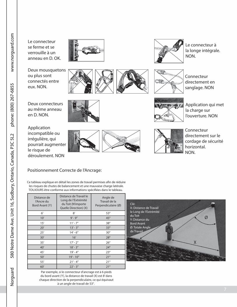
Correct Anchorage Positioning:
This chart details allowable working zones requiredto reduce risk of swing falls and improper side loading.
ALWAYS adhere to information speci�ed by chart.
Anchor DistanceFrom
Leading Edge (Y)
Working DistanceAlong Roof Edge
(Either Direction) (X)
Working AngleFrom
Perpendicular (Ø)
6’10’
15’20’25’
30’
35’40’45’50’55’60’
8’9’ - 9”
11’ - 7”13’ - 3”14’ - 6”
16’
17’ - 2”18’ - 3”19’ - 4”
19’ - 10”21’ - 4”22’ - 3”
53°45°
38°33°30°
28°
26°24°23°21°21°21°
For example, if the anchorage connector is 6 feet from the leadingedge (Y), the working distance (X) is 8’ in each direction fromthe perpendicular, which translates to a 53° working angle.
Key:X: Working DistanceAlong Roof EdgeY: Distance FromLeading EdgeØ: Total WorkingAngle
Y
X
Ø
7
N
orgu
ard
580
Not
re D
ame
Ave.
Uni
t 16,
Sud
bury
, Ont
ario
, Can
ada,
P3C
5L2
pho
ne: (
800)
267
-685
5
ww
w.n
orgu
ard.
com

8
Components and Speci�cations
Part # Length Description
10900CSA
10901CSA
10’ (3m)
10’ (3m)
Type 1 SRL. Aramid Fiber Webbing w/Carabiner, Swivel Top, & Snap Hook
Type 1 SRL. Aramid Fiber Webbing w/Carabiner, Swivel Top & Rebar Hook
10909CSA
10910CSA
10912CSA
20’ (6.1m)
20’ (6.1m)
25’ (7.6m)
Type 2 SRL. Aramid Fiber Webbing w/Carabiner, Swivel Top, Snap Hook, & Tag Line
Type 2 SRL. 3/16” (.47cm) Galvanized Cable w/Carabiner, Swivel Top, Snap Hook, & Tag Line
Type 2 SRL. 3/16” (.47cm) Galvanized Cable w/Carabiner, Swivel Top, Snap Hook, & Tag Line
10915CSA
10932CSA
10930CSA
10935CSA
30’ (9.1m)
20’ (6.1m)
25’ (7.6m)
30’ (9.1m)
Type 2 SRL. 3/16” (.47cm) Galvanized Cable w/Carabiner, Swivel Top, Snap Hook, & Tag Line
Type 2 SRL. 3/16” (.47cm) Stainless Steel Cable w/Carabiner, Swivel Top, Snap Hook, & Tag Line
Type 2 SRL. 3/16” (.47cm) Stainless Steel Cable w/Carabiner, Swivel Top, Snap Hook, & Tag Line
Type 2 SRL. 3/16” (.47cm) Stainless Steel Cable w/Carabiner, Swivel Top, Snap Hook, & Tag Line
10993CSA
10994CSA
10995CSA
10996CSA
10997CSA
10998CSA
6’ (1.8m)
10’ (3m)
10’ (3m)
6’ (1.8m)
10’ (3m)
6’ (1.8m)
Type 1 SRL. G-Link Dual Retractable System w/Aluminum Snap Hooks
Type 1 SRL. G-Link Dual Retractable System w/Aluminum Snap Hooks
Type 1 SRL. G-Link Dual Retractable System w/Steel Rebar Hooks
Type 1 SRL. G-Link Dual Retractable System w/Steel Rebar Hooks
Type 1 SRL. G-Link Dual Retractable System w/Aluminum Rebar Hooks
Type 1 SRL. G-Link Dual Retractable System w/Aluminum Rebar Hooks
10917CSA
10918CSA
10937CSA
10938CSA
50’ (15.3m)
65’ (19.8m)
50’ (15.3m)
65’ (19.8m)
Type 2 SRL. 3/16” (.47cm) MK Galvanized Cable w/Swivel Top & High Strength Snap Hook
Type 2 SRL. 3/16” (.47cm) MK Galvanized Cable w/Swivel Top & High Strength Snap Hook
Type 2 SRL. 3/16” (.47cm) MK Stainless Steel Cable w/Carabiner, Swivel Top, Snap Hook, & Tag Line
Type 2 SRL. 3/16” (.47cm) MK Stainless Steel Cable w/Carabiner, Swivel Top, Snap Hook, & Tag Line
10908CSA
10911CSA
10913CSA
10916CSA
10921CSA
10923CSA
10931CSA
10933CSA
10936CSA
20’ (6.1m)
20’ (6.1m)
25’ (7.6m)
30’ (9.1m)
20’ (6.1m)
25’ (7.6m)
20’ (6.1m)
25’ (7.6m)
30’ (9.1m)
10920CSA
10922CSA
10925CSA
10927CSA
10928CSA
20’ (6.1m)
25’ (7.6m)
30’ (9.1m)
50’ (15.3m)
65’ (19.8m)
Type 2 SRL. 1” (2.54cm) Nylon Webbing w/Carabiner, Swivel Top, & Boot Cover
Type 2 SRL. 3/16” (.47cm) Galvanized Cable w/Swivel Top, Swivel Snap Hook, & Boot Cover
Type 2 SRL. 3/16” (.47cm) Galvanized Cable w/Swivel Top, Swivel Snap Hook, & Boot Cover
Type 2 SRL. 3/16” (.47cm) Galvanized Cable w/Swivel Top, Swivel Snap Hook, & Boot Cover
Type 2 SRL. 3/16” (.47cm) Stainless Steel Cable w/Swivel Top, Swivel Snap Hook, & Boot Cover
Type 2 SRL. 3/16” (.47cm) Stainless Steel Cable w/Swivel Top, Swivel Snap Hook, & Boot Cover
Type 2 SRL. 3/16” (.47cm) Stainless Steel Cable w/Swivel Top, Swivel Snap Hook, & Boot Cover
Type 2 SRL. Leading Edge Certi�ed w/Shock Absorber and Boot Cover
Type 2 SRL. Leading Edge Certi�ed w/Shock Absorber and Boot Cover
Type 2 SRL. Leading Edge Certi�ed w/Shock Absorber and Boot Cover
Type 2 SRL. Leading Edge Certi�ed w/Shock Absorber and Boot Cover
Type 2 SRL. Leading Edge Certi�ed w/Shock Absorber and Boot Cover
10926CSA 30’ (9.1m)
Type 2 SRL. HD 3/16” (.47cm) Galvanized Cable w/Swivel Top, Swivel Snap Hook, & Boot Cover
Type 2 SRL. HD 3/16” (.47cm) Galvanized Cable w/Swivel Top, Swivel Snap Hook, & Boot Cover
Type 2 SRL. HD 3/16” (.47cm) Galvanized Cable w/Swivel Top, Swivel Snap Hook, & Boot Cover
N
orgu
ard
580
Not
re D
ame
Ave.
Uni
t 16,
Sud
bury
, Ont
ario
, Can
ada,
P3C
5L2
pho
ne: (
800)
267
-685
5
ww
w.n
orgu
ard.
com

9
Consult manufacturer for model-speci�c material composition.SRLs made from some of all of the following components:Aluminum, galvanized steel, stainless steel, nylon, polyester, and ABS plastic.
Connector(Snap Hook orRebar Hook)
Carabinerattachment point
Lifeline Housing
Lifeline
*Part #s: 10917CSA, 10918CSA, 10937CSA, 10938CSA, 10974CSA, and 10981CSA are not currentlyavailable. Contact Norguard for more information.
Part # Length Description
10946CSA
10950CSA
10’ (3m)
10’ (3m) Type 1 SRL. Heavy Duty Yellow Jacket Cable SRL w/Shock Pack
Type 1 SRL. Yellow Jacket Cable SRL w/High Strength Swivel Snap Hook
10952CSA
10956CSA
10957CSA
10’ (3m)
10’ (3m)
10’ (3m)
Type 1 SRL. Yellow Jacket Cable SRL w/Aluminum Rebar Hook
Type 1 SRL. Yellow Jacket Cable SRL w/High Strength Non-Indicating Snap Hook
Type 1 SRL. Yellow Jacket Cable SRL w/High Strength Indicating Snap Hook
10974CSA
10984CSA
10981CSA
10985CSA
10987CSA
10989CSA
11009CSA
50’ (15.3m)
65’ (19.8m)
50’ (15.3m)
25’ (7.6m)
20’ (6.1m)
16’ (4.9m)
80’ (24.4m)
Type 3 SRL. 3/16” (.47cm) 3-Way Rescue/Retrieval SRL.
Type 3 SRL. 3/16” (.47cm) 3-Way Rescue/Retrieval SRL.
Type 2 SRL. 3/16” (.47cm) Galvanized Cable w/Swivel Top, Swivel Snap Hook, & Carabiner
Type 2 SRL. 3/16” (.47cm) Galvanized Cable w/Swivel Top, Swivel Snap Hook, & Carabiner
Type 2 SRL. 3/16” (.47cm) Galvanized Cable w/Swivel Top, Swivel Snap Hook, & Carabiner
Type 2 SRL. 3/16” (.47cm) Galvanized Cable w/Swivel Top, Swivel Snap Hook, & Carabiner
Type 2 SRL. 3/16” (.47cm) Galvanized Cable w/Swivel Top, Swivel Snap Hook, & Carabiner
Example Norguard SRL:
Example impact indicator:• Green: Undeployed
• Red: Deployed
*Shock absorber thatshows signs of
deployment alsofunctions as an
impact indicator.
10910ARCSA 20’ (6.1m) Type 2 SRL. 3/16” (.47cm) Galvanized Cable w/Carabiner, Swivel Top, Aluminum Snap Hook, & Tag Line
10912ARCSA 25’ (7.6m)
10915ARCSA 30’ (9.1m)
Type 2 SRL. 3/16” (.47cm) Galvanized Cable w/Carabiner, Swivel Top, Aluminum Snap Hook, & Tag Line
Type 2 SRL. 3/16” (.47cm) Galvanized Cable w/Carabiner, Swivel Top, Aluminum Snap Hook, & Tag Line
N
orgu
ard
580
Not
re D
ame
Ave.
Uni
t 16,
Sud
bury
, Ont
ario
, Can
ada,
P3C
5L2
pho
ne: (
800)
267
-685
5
ww
w.n
orgu
ard.
com
10
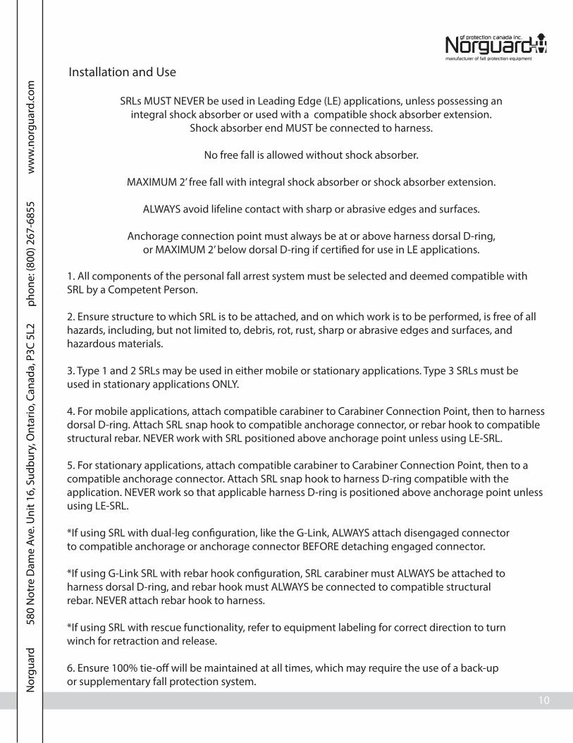
Installation and Use
SRLs MUST NEVER be used in Leading Edge (LE) applications, unless possessing anintegral shock absorber or used with a compatible shock absorber extension.
Shock absorber end MUST be connected to harness.
No free fall is allowed without shock absorber.
MAXIMUM 2’ free fall with integral shock absorber or shock absorber extension.
ALWAYS avoid lifeline contact with sharp or abrasive edges and surfaces.
Anchorage connection point must always be at or above harness dorsal D-ring,or MAXIMUM 2’ below dorsal D-ring if certi�ed for use in LE applications.
1. All components of the personal fall arrest system must be selected and deemed compatible withSRL by a Competent Person.
2. Ensure structure to which SRL is to be attached, and on which work is to be performed, is free of allhazards, including, but not limited to, debris, rot, rust, sharp or abrasive edges and surfaces, andhazardous materials.
3. Type 1 and 2 SRLs may be used in either mobile or stationary applications. Type 3 SRLs must beused in stationary applications ONLY.
4. For mobile applications, attach compatible carabiner to Carabiner Connection Point, then to harnessdorsal D-ring. Attach SRL snap hook to compatible anchorage connector, or rebar hook to compatiblestructural rebar. NEVER work with SRL positioned above anchorage point unless using LE-SRL.
5. For stationary applications, attach compatible carabiner to Carabiner Connection Point, then to acompatible anchorage connector. Attach SRL snap hook to harness D-ring compatible with theapplication. NEVER work so that applicable harness D-ring is positioned above anchorage point unlessusing LE-SRL.
*If using SRL with dual-leg con�guration, like the G-Link, ALWAYS attach disengaged connectorto compatible anchorage or anchorage connector BEFORE detaching engaged connector.
*If using G-Link SRL with rebar hook con�guration, SRL carabiner must ALWAYS be attached toharness dorsal D-ring, and rebar hook must ALWAYS be connected to compatible structuralrebar. NEVER attach rebar hook to harness.
*If using SRL with rescue functionality, refer to equipment labeling for correct direction to turnwinch for retraction and release.
6. Ensure 100% tie-o� will be maintained at all times, which may require the use of a back-upor supplementary fall protection system.
N
orgu
ard
580
Not
re D
ame
Ave.
Uni
t 16,
Sud
bury
, Ont
ario
, Can
ada,
P3C
5L2
pho
ne: (
800)
267
-685
5
ww
w.n
orgu
ard.
com

11
LE SRL Additional Use Instructions:
LE SRLs are tested and certi�ed for horizontal use over a steel edge without burrs. LE SRLs may beused over similar surfaces, such as metal sheeting or other steel formations.
The allowable angle of redirection of the lifeline portion of LE SRLs at the leading edge of a fall hazardMUST be at least 90° (see Image 1).
Anchor point MUST be situated no lower than the leading edge of applicable fall hazard(s).
Prior to use, a Competent Person MUST calculate adequate fall clearance (see pg. 6).
LE SRLs may be used in combination with horizontal lifelines. All installation, set-up, and use ofhorizontal lifelines must be done under the supervision of a Quali�ed Person.
NEVER work on the far side of an opening that is opposite the LE SRL anchorage point.
In the event of a fall over the edge, special rescue measures may be necessary. Always account foruse of LE SRLs in job site rescue plan developed by job site Competent Person.
Setback Distance
Image 1 Image 2
Leading Edge
ALWAYS adhere to the following warnings and speci�cations when using LE SRLs.! WARNING
ALWAYS attach to anchorage connector that will allow for required setback distance (see Image 2).
•Setback distance: As determined by product testing, Norguard LE SRLs MUST be installed a MINIMUM 6’ (1.8m) from the leading edge of applicable fall hazard(s).
X≤90°
X≥90°
N
orgu
ard
580
Not
re D
ame
Ave.
Uni
t 16,
Sud
bury
, Ont
ario
, Can
ada,
P3C
5L2
pho
ne: (
800)
267
-685
5
ww
w.n
orgu
ard.
com

12
Recerti�cation
Type 1 SRL:
All Type 1 SRLs MUST be removed from service if exposed to forces of fall arrest. Type 1 SRLs are notrepairable, and do not require recerti�cation by the manufacturer for continued use. As long as SRLpasses all inspection requirements speci�ed by this instruction manual, the lifetime of SRLs thatpossess a webbing lifeline is 5 years from the date of �rst use, or from the date of manufacture if thedate of �rst use is not recorded, and the lifetime of SRLs that possess a cable lifeline is inde�nite.
Type 2 SRL:
All Type 2 SRLs MUST be removed from service if exposed to forces of fall arrest, and returned to themanufacturer for repair. Type 2 SRLs MUST be returned to the manufacturer for inspection,maintenance, and recerti�cation for continued use no more than 2 years after the date ofmanufacture, and annually thereafter. After initial recerti�cation, manufacturer will label SRL with nextrequired recerti�cation date. Provided that SRL is recerti�ed by the manufacturer according toinstruction speci�cations, and as long as SRL passes all inspection requirements speci�ed by thisinstruction manual, the lifetime of SRLs that possess a webbing lifeline is 5 years from the date of �rstuse, or from the date of manufacture if the date of �rst use is not recorded, and the lifetime of SRLsthat possess a cable lifeline is inde�nite.
Type 3 SRL:
All Type 3 SRLs MUST be removed from service if exposed to forces of fall arrest, and returned to themanufacturer for repair. Type 3 SRLs MUST be returned to the manufacturer for inspection,maintenance, and recerti�cation for continued use no more than 2 years after the date ofmanufacture, and annually thereafter. After initial recerti�cation, manufacturer will label SRL with nextrequired recerti�cation date. Provided that SRL is recerti�ed by the manufacturer according toinstruction speci�cations, and as long as SRL passes all inspection requirements speci�ed by thisinstruction manual, the lifetime of SRLs that possess a webbing lifeline is 5 years from the date of �rstuse, or from the date of manufacture if the date of �rst use is not recorded, and the lifetime of SRLsthat possess a cable lifeline is inde�nite.
For reference only.Background to be clear.
For reference only.No border around label.
1/2”(1.27cm)
1” (2.54cm)
To Be Recerti�edOn Or Before
Recerti�cation Label: • Will be affixed to SRL upon its return to user after manufacturer recertification.
N
orgu
ard
580
Not
re D
ame
Ave.
Uni
t 16,
Sud
bury
, Ont
ario
, Can
ada,
P3C
5L2
pho
ne: (
800)
267
-685
5
ww
w.n
orgu
ard.
com

13
Labels
10900CSA, 10901CSA:
10909CSA, 10910CSA, 10912CSA, 10915CSA, 10930CSA, 10932CSA, 10935CSA, 10910ARCSA,10912ARCSA,10915ARCSA:
OSHA 1926.502, 1910.66ANSI Z359.14-2012, A10.32-2012
CSA Z259.2.2-98
SELF
-RETRACTING LIFELINE
J F M AA JM J S O N DYR
YR
YR
YR
YR
20’ 1” WEB6m 2.54cm TOILE
20’ 3/16” CABLE6m .47cm CABLE
25’ 3/16” CABLE7.6m .47cm CABLE
30’ 3/16” CABLE9.1m .47cm CABLE
Serial # / # de SérieLot # / # de Lot Mfg. Date / Date de Fabrication
10909CSA
ANSI Z359.14-2012, A10.32-2012OSHA 1926.502, 1910.66
CSA Z259.2.2-98
_____/_____Date of first use /
Date de la première utilisation
INSPECTION: Inspect unit in accordance to the manufacturer’s instruction manual and regulatory guidelines. Check lifeline retraction by pulling out a minimum 4 ft. of lifeline and allowing it to retract under light tension, lifeline should retract completely. Pull sharply to test locking function, brakes must engage. Before use, inspect the lifeline condition, function and condition of fasteners, and legibility of labels. Also, check for evidence of defects, damage or missing parts. User must inspect the impact indicator for signs of activation. Device must be taken out of
service after arresting a fall or if the impact indicator show signs of activation. / Appareil doit être mis hors service après avoir
arête une chute ou si l’indcateur d’impact montre des signes d’activation. Do not use if inspection reveals an unsafe condition. Unit must be inspected by a trained and Competent Person at least monthly. This device must be sent back to the manufacturer or an authorized service
center a maximum of 2 years after date of manufacture for recertification, and annually thereafter. / Cet appareil
doit être renvoyé au fabricant ou à un centre de service autorisé un maximum de 2 ans après la date de fabrication de l’inspection fabricant, et annuellement par la suite.
90063 (Rev. A)
SPECIFICATIONS:Class B SRLType 2 SRL / Catégorie 2Average arresting force: 900 lbs.Maximum arresting force: 1,800 lbs. / Force d’arrêt max: 816.4 kgMaximum arresting distance: 54 in. / Distance maximale d’arrêt: 137.1 cmCapacity Range: 130-310 lbs. / Plage de puissance: 58.9-140.6 kg
WARNING: Prior to use, fully read and understand all manufacturer’s instructions provided with equipment at time of
shipment. / Suivre toutes les instructions du fabricant incluses au moment de l’expédition. DO NOT ATTEMPT TO SELF
SERVICE OR REPAIR! DO NOT REMOVE THIS LABEL.
USE: Always use in accordance with manufacturer’s instruction manual and labels included with this device at the time of shipment.
This device is only for use by one person as a fall arrester. / Cet appareil doit uniquement êntre utilisê par une seule personne
comme un atichute. Always connect the snap hook directly to the attachment point on the safety harness. Guard against
swing-falls by keeping the lifeline vertically overhead. No free fall is allowed. SRL must always be positioned at or
above harness D-ring. Do not allow lifeline to come in contact with sharp or abrasive edges and surfaces.
Ensure that connection to anchorage is secured properly before use. May be used as a component of a PFAS in HLL applications. Design, installation, and utilization of HLLs must be supervised by a Qualified Person. Unsuitable for
horizontal use.
10910CSA (g)
10930CSA (ss)
10910ARCSA
10912CSA (g)
10932CSA (ss)
10915CSA (g)
10935CSA (ss)CUSTOMCOUTUME
10912ARCSA 10915ARCSA
OSHA 1926.502, 1910.66ANSI Z359.14-2012, A10.32-2012
CSA Z259.2.2-98
Max. arresting distance: 54 in / Distance maximale d’arrêt: 137.1 cmMax. arresting force: 1,800 lbs. / Force d'arrêt max: 816.4 kgCapacity Range: 130-310 lbs. / Plage de puissance: 58.9-140.6 kgAverage arresting force: 900 lbs.Type 1 SRL / Catégorie 1Class B SRL
WARNING: Prior to use,fully read and understand all manufacturer’s instructions
provided with equipment at time of shipment. / Suivre toutes les instructions du fabricant
incluses au moment de l’expédition. DO NOT ATTEMPT TO SELF SERVICE OR
REPAIR! DO NOT REMOVE THIS LABEL.
USE: Always use in accordance with manufacturer’s instruction manual and labels
included with this device at the time of shipment. This device is only for use by
one person as a fall arrester. / Cet appareil doit uniquement êntre utilisê par une seule
personne comme un atichute. Always connect the snap hook directly to the attachment point on the safety harness. Guard against swing-falls by keeping the
lifeline vertically overhead. No free fall is allowed. SRL must always be positioned at or above harness
D-ring. Do not allow lifeline to come in contact with sharp or abrasive edges and surfaces. Ensure that connection to anchorage is secured properly
before use. May be used as a component of a PFAS in HLL applications. Design, installation and utilization of HLLs must be supervised by a
Qualified Person. Unsuitable for horizontal use.
90062 (Rev. A)
_____/_____Date of first use /Date de la première utilisation
INSPECTION: Before use, inspect the lifeline condition, function and condition of fasteners, and legibility of labels. Also, check for evidence of defects, damage or missing parts. User must inspect the impact indicator for signs of activation. Check lifeline retraction by pulling out a minimum 4 ft. of lifeline and allowing it to retract under light tension, lifeline should retract completely. Pull sharply to test locking
function, brakes must engage. Device must be taken out of service after arresting a fall or if the
impact indicator show signs of activation. / Appareil doit être mis hors service après avoir arête une chute ou si l’indcateur d’impact montre des signes d’activation.
Inspection by a Competent Person required monthly.
Serial # / # de SérieLot # / # de Lot Mfg. Date / Date deFabrication
10' Nylon, 7/8" Width3m Nylon, 2.2cm Largeur
10900CSA 10901CSA
Front Back
Front
Back
N
orgu
ard
580
Not
re D
ame
Ave.
Uni
t 16,
Sud
bury
, Ont
ario
, Can
ada,
P3C
5L2
pho
ne: (
800)
267
-685
5
ww
w.n
orgu
ard.
com
14
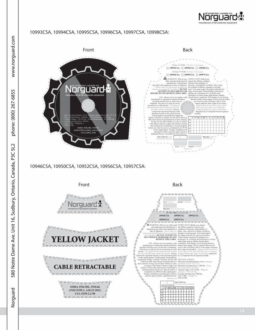
10993CSA, 10994CSA, 10995CSA, 10996CSA, 10997CSA, 10998CSA:
10946CSA, 10950CSA, 10952CSA, 10956CSA, 10957CSA:
OSHA 1926.502, 1910.66ANSI Z359.14-2012, A10.32-2012
CSA Z259.2.2-98
Max. arresting distance: 54 in / Distance maximale d’arrêt: 137.1 cmMax. arresting force: 1,800 lbs. / Force d'arrêt max: 816.4 kgCapacity Range: 130-310 lbs. / Plage de puissance: 58.9-140.6 kgAverage arresting force: 900 lbs.Type 1 SRL / Catégorie 1Class B SRL
WARNING: Prior to use,fully read and understand all manufacturer’s instructions
provided with equipment at time of shipment. / Suivre toutes les instructions du fabricant
incluses au moment de l’expédition. DO NOT ATTEMPT TO SELF SERVICE OR
REPAIR! DO NOT REMOVE THIS LABEL.
USE: Always use in accordance with manufacturer’s instruction manual and labels
included with this device at the time of shipment. This device is only for use by
one person as a fall arrester. / Cet appareil doit uniquement êntre utilisê par une seule
personne comme un atichute. Always connect the snap hook directly to the attachment point on the safety harness. Guard against swing-falls by keeping the
lifeline vertically overhead. No free fall is allowed. SRL must always be positioned at or above harness
D-ring. Do not allow lifeline to come in contact with sharp or abrasive edges and surfaces. Ensure
that connection to anchorage is secured properly before use. May be used as a component of a PFAS
in HLL applications. Design, installation and utilization of HLLs must be supervised by a
Qualified Person. Unsuitable for horizontal use.
____/____Date of first use / Datede la première utilisation
INSPECTION: Before use, inspect the lifeline condition, function and condition of fasteners, and legibility of labels. Also, check for evidence of defects, damage or missing parts. User must inspect the impact indicator for signs of activation. Check lifeline retraction by pulling out a minimum 4 ft. of lifeline and allowing it to retract under light tension, lifeline should retract completely. Pull sharply to test locking
function, brakes must engage. Device must be taken out of service after arresting a fall or if the
impact indicator show signs of activation. / Appareil doit être mis hors service après avoir arête une chute ou si l’indcateur d’impact montre des signes d’activation.
Inspection by a Competent Person required monthly.
Serial # / # de SérieLot # / # de Lot
Mfg. Date / Datede Fabrication
6' Nylon, 7/8" Width / 1.8m Nylon, 2.2cm Largeur
10993CSA 10996CSA 10998CSA10' Nylon, 7/8" Width / 3m Nylon, 2.2cm Largeur
10994CSA 10995CSA 10997CSA
90064 (Rev. A)
Front Back
WARNING: Prior to use, fully read and understand all manufacturer’s
instructions provided with equipment at time of shipment. / Suivre toutes les
instructions du fabricant incluses au moment de l’expédition. DO NOT ATTEMPT TO
SELF SERVICE OR REPAIR! DO NOT REMOVE THIS LABEL.
USE: Always use in accordance with manufacturer’s instruction manual and labels
included with this device at the time of shipment. This device is only for use by one person as a fall
arrester. / Cet appareil doit uniquement êntre utilisê par une seule personne comme un atichute. Always
connect the snap hook directly to the attachment point on the safety harness. Guard against swing-falls by
keeping the lifeline vertically overhead. No free fall is allowed. SRL must always be positioned at or
above harness D-ring. Do not allow lifeline to come in contact with sharp or abrasive edges and
surfaces. Ensure that connection to anchorage is secured properly before use. May be used as a
component of a PFAS in HLL applications. Design, installation and utilization of HLLs
must be supervised by a Qualified Person.90067 (Rev. A)
INSPECTION: Before use, inspect the lifeline condition, function and condition of fasteners, and legibility of labels. Also, check for evidence of defects, damage or missing parts. User must inspect the impact indicator for signs of activation. Check lifeline retraction by pulling out a minimum 4 ft. of lifeline and allowing it to retract under light tension, lifeline should retract completely. Pull sharply to test locking function, brakes must engage. Device must be taken out of service after arresting a fall or if the impact indicator show signs of activation. / Appareil doit être mis hors service après avoir arête une chute ou si l’indcateur d’impact montre des signes d’activation. Inspection by a Competent Person required monthly.
SPECIFICATIONS:Maximum arresting distance: 54 in / Distance maximale d’arrêt: 137.1 cmMaximum arresting force: 1,800 lbs. / Force d'arrêt maximale: 816.4 kgCapacity range: 130-310 lbs. / Plage de puissance: 58.9-140.6 kgAverage arresting force: 900 lbs.Type 1 SRL / Catégorie 1Class B SRL
Serial # / # de SérieLot # / # de Lot
Mfg. Date / Date de Fabrication
10' 3/16" Cable / 3m .47cm Cable
10946CSA 10950CSA
10956CSA 10957CSA
10952CSA
____/____ Date of first use /Date de la première utilisation
OSHA 1926.502, 1910.66ANSI Z359.1, A10.32-2012,
CSA Z259.2.2-98
Front Back
N
orgu
ard
580
Not
re D
ame
Ave.
Uni
t 16,
Sud
bury
, Ont
ario
, Can
ada,
P3C
5L2
pho
ne: (
800)
267
-685
5
ww
w.n
orgu
ard.
com
15
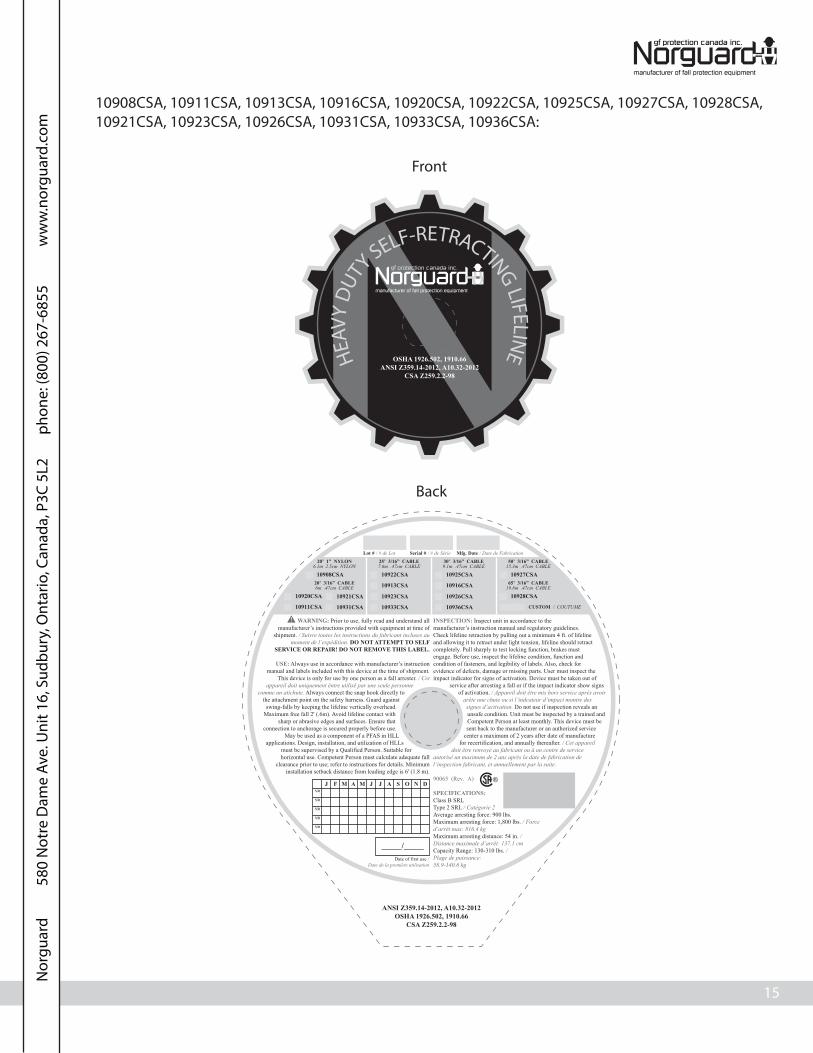
10908CSA, 10911CSA, 10913CSA, 10916CSA, 10920CSA, 10922CSA, 10925CSA, 10927CSA, 10928CSA,10921CSA, 10923CSA, 10926CSA, 10931CSA, 10933CSA, 10936CSA:
OSHA 1926.502, 1910.66ANSI Z359.14-2012, A10.32-2012
CSA Z259.2.2-98
HEAV
Y D
UTY SELF-RETRACTING LIFELIN
E
25’ 3/16” CABLE7.6m .47cm CABLE
30’ 3/16” CABLE9.1m .47cm CABLE
50’ 3/16” CABLE15.3m .47cm CABLE
Serial # / # de SérieLot # / # de Lot Mfg. Date / Date de Fabrication
ANSI Z359.14-2012, A10.32-2012OSHA 1926.502, 1910.66
CSA Z259.2.2-98
J F M AA JM J S O N DYR
YR
YR
YR
YR
_____/_____Date of first use /
Date de la première utilisation
INSPECTION: Inspect unit in accordance to the manufacturer’s instruction manual and regulatory guidelines. Check lifeline retraction by pulling out a minimum 4 ft. of lifeline and allowing it to retract under light tension, lifeline should retract completely. Pull sharply to test locking function, brakes must engage. Before use, inspect the lifeline condition, function and condition of fasteners, and legibility of labels. Also, check for evidence of defects, damage or missing parts. User must inspect the impact indicator for signs of activation. Device must be taken out of
service after arresting a fall or if the impact indicator show signs of activation. / Appareil doit être mis hors service après avoir
arête une chute ou si l’indcateur d’impact montre des signes d’activation. Do not use if inspection reveals an unsafe condition. Unit must be inspected by a trained and Competent Person at least monthly. This device must be sent back to the manufacturer or an authorized service
center a maximum of 2 years after date of manufacture for recertification, and annually thereafter. / Cet appareil
doit être renvoyé au fabricant ou à un centre de service autorisé un maximum de 2 ans après la date de fabrication de l’inspection fabricant, et annuellement par la suite.
90065 (Rev. A)
SPECIFICATIONS:Class B SRLType 2 SRL / Catégorie 2Average arresting force: 900 lbs.Maximum arresting force: 1,800 lbs. / Force d’arrêt max: 816.4 kgMaximum arresting distance: 54 in. / Distance maximale d’arrêt: 137.1 cmCapacity Range: 130-310 lbs. / Plage de puissance: 58.9-140.6 kg
WARNING: Prior to use, fully read and understand all manufacturer’s instructions provided with equipment at time of
shipment. / Suivre toutes les instructions du fabricant incluses au moment de l’expédition. DO NOT ATTEMPT TO SELF
SERVICE OR REPAIR! DO NOT REMOVE THIS LABEL.
USE: Always use in accordance with manufacturer’s instruction manual and labels included with this device at the time of shipment.
This device is only for use by one person as a fall arrester. / Cet appareil doit uniquement êntre utilisê par une seule personne
comme un atichute. Always connect the snap hook directly to the attachment point on the safety harness. Guard against
swing-falls by keeping the lifeline vertically overhead. Maximum free fall 2' (.6m). Avoid lifeline contact with
sharp or abrasive edges and surfaces. Ensure that connection to anchorage is secured properly before use.
May be used as a component of a PFAS in HLL applications. Design, installation, and utilization of HLLs
must be supervised by a Qualified Person. Suitable for horizontal use. Competent Person must calculate adequate fall
clearance prior to use; refer to instructions for details. Minimum installation setback distance from leading edge is 6' (1.8 m).
10922CSA10908CSA
10913CSA
10923CSA
20’ 3/16” CABLE6m .47cm CABLE
20’ 1” NYLON6.1m 2.5cm NYLON
10920CSA
10911CSA
10925CSA
10916CSA
10927CSA65’ 3/16” CABLE
19.8m .47cm CABLE
10928CSA10926CSA
10933CSA
10921CSA
10931CSA 10936CSA CUSTOM / COUTUME
Front
Back
N
orgu
ard
580
Not
re D
ame
Ave.
Uni
t 16,
Sud
bury
, Ont
ario
, Can
ada,
P3C
5L2
pho
ne: (
800)
267
-685
5
ww
w.n
orgu
ard.
com

16
retractable
J F M AA JM J S O N DYR
YR
YR
YR
YR
_____/_____Date of first use /Date de la première utilisation
ANSI Z359.14-2012, A10.32-2012OSHA 1926.502, 1910.66 CSA Z259.2.2-98
16’ 3/16” CABLE4.9m .47cm CABLE
20’ 3/16” CABLE6.1m .47cm CABLE
25’ 3/16” CABLE7.7m .47cm CABLE
50’ 3/16” CABLE15.3m .47cm CABLE
Serial # / # de SérieLot # / # de Lot Mfg. Date / Date de Fabrication
10984CSA10989CSA 10985CSA 10987CSA
80’ 3/16” CABLE24.4m .47cm CABLE
11009CSA
WARNING: Prior to use, fully read and understand all manufacturer’s instructions provided with equipment
at time of shipment. / Suivre toutes les instructions du fabricant incluses au moment de l’expédition.DO NOT
ATTEMPT TO SELF SERVICE OR REPAIR! DO NOT REMOVE THIS LABEL!
USE: Always use in accordance with manufacturer’s instruction manual and labels included with this device at the time of
shipment. This device is only for use by one person as a fall arrester. / Cet appareil doit uniquement êntre utilisê par une
seule personne comme un atichute. Always connect the snap hook directly to the attachment point on the safety
harness. Guard against swing-falls by keeping the lifeline vertically overhead. No free fall is allowed. SRL must always be positioned at or above harness
D-ring. Do not allow lifeline to come in contact with sharp or abrasive edges and surfaces. Ensure that
connection to anchorage is secured properly before use. May be used as a component of a PFAS in HLL
applications. Design, installation, and utilization of HLLs must be supervised by a Qualified Person. Unsuitable for horizontal use.
INSPECTION: Inspect unit in accordance to the manufacturer’s instruction manual and regulatory guidelines. Check lifeline retraction by pulling out a minimum 4 ft. of lifeline and allowing it to retract under light tension, lifeline should retract completely. Pull sharply to test locking function, brakes must engage. Before use, inspect the lifeline condition, function and condition of fasteners, and legibility of labels. Also, check for evidence of defects, damage or missing parts. User must inspect the impact indicator for signs of activation. Device must be taken out of
service after arresting a fall or if the impact indicator show signs of activation. / Appareil doit être mis hors service
après avoir arête une chute ou si l’indcateur d’impact montre des signes d’activation. Do not use if inspection reveals an unsafe condition. Unit must be inspected by a trained and Competent Person at least monthly. This device must be sent back to the manufacturer or an
authorized service center a maximum of 2 years after date of manufacture for recertification, and annually
thereafter. / Cet appareil doit être renvoyé au fabricant ou à un centre de service autorisé un maximum de 2 ans après la date
de fabrication de l’inspection fabricant, et annuellement par la suite.
SPECIFICATIONS:Type 2 SRL / Catégorie 2Class B SRLAverage arresting force: 900 lbs.Maximum arresting force: 1,800 lbs. / Force d’arrêt max: 816.4 kgMaximum arresting distance: 54 in. / Distance maximale d’arrêt: 137.1 cmCapacity range: 130-310 lbs. / Plage de puissance: 58.9-140.6 kg
90068 (Rev. A)
10984CSA, 10985CSA, 10987CSA, 10989CSA, 11009CSA:
Front
Back
N
orgu
ard
580
Not
re D
ame
Ave.
Uni
t 16,
Sud
bury
, Ont
ario
, Can
ada,
P3C
5L2
pho
ne: (
800)
267
-685
5
ww
w.n
orgu
ard.
com

17
Inspection Log
Notes
If equipment fails inspection IMMEDIATELY REMOVE FROM SERVICE.
User must inspect prior to EACH use. Competent Person must complete formal inspection atleast EVERY month. Competent Person to inspect and initial inspection log and SRL inspectiongrid label.
Date of �rst use: __________________. As long as SRL passes pre-use and Competent Personinspections and is recerti�ed as required by this instruction manual, product lifetime for SRLwith webbing lifeline is 5 years from date of �rst use, or, if not recorded, from date ofmanufacture, and product lifetime for SRL with cable lifeline is inde�nite.
This inspection log must be speci�c to one SRL. Separate inspection logs must be used for eachSRL. All inspection records must be made visible and available to all users at all times.
N
orgu
ard
580
Not
re D
ame
Ave.
Uni
t 16,
Sud
bury
, Ont
ario
, Can
ada,
P3C
5L2
pho
ne: (
800)
267
-685
5
ww
w.n
orgu
ard.
com

Cordage de Sécurité Auto-Rétractable de Norguard
Mode d’Emploi
Ne pas jeter ces instructions!Veuillez lire et comprendre ces instructions avant l’utilisation de l’equipment!
No. du formulaire QD 154 Mars-13. Rév. (0)

6
AUTOMNE LE CALCUL DU PASSAGE
Longueur cordon(6’ total)
Facteur de Sécurité(3’ total)
Décélérationdistance (4’ total)
Hauteur du harnaisanneau en D arrière
des pieds du travailleur(6’ total)
Distancerequise entre
anchorage(19’ total)
Limitations
Compatibilité: Lorsque des connexions sont faites avec les CSAR, éliminez toute possibilité dedéroulement. Le déroulement survient quand l’interférence entre un crochet et le point d’attachecause au crochet de s’ouvrir involontairement et de lâcher. Toutes les connexions doivent être choisieset considérées comme compatibles avec les CSAR par une Personne Compétente. Tous les connecteursdoivent se verrouiller et se fermer automatiquement, et supporter des charges minimum de 3,600livres. Voir ce que suit à titre d’exemple sur les connexions compatibles et incompatibles:
Les Chutes de Balancement: Avant toute installation ou utilisation,prendre en compte l’élimination ou la minimisation de tous les dangersde balance de chute. Les chutes de balancement se produisent quandl’ancre n’est pas directement au-dessus de l’endroit où la chute se produit.Travailler toujours le plus près possible en ligne avec le point d’ancre. Leschutes de balancement augmentent de façon signi�cative la probabilitéde blessures graves ou même la mort dans le cas d’une chute.
Espace Dégagé en cas de Chute: Il doit y avoir su�sammentd’espace dégagé en-dessous du connecteur d’ancrage pour prévenirune chute avant que l’utilisateur ne touche le sol ou un obstacle.Lors du calcul de l’espace dégagé en cas de chute, prendre encompte un facteur de sécurité MINIMUN de 3’, la distance dedécélération, la taille de l’utilisation, la longueur la onge/ CSAR,et tous les autres facteurs applicables. Diagramme ci est unexemple de calcul dégagement d'automne seulement.
Espace Con�né/de Sauvetage: Les CSAR conçus avec des capacités de descente et demontée, par l’utilisation d’une manivelle électronique ou manuel, peuvent être utilisésdans des applications d’espace con�né/ de sauvetage. Les systèmes de sauvetage sontutilisés a�n de récupérer en toute sécurité un travaileur d’un lieu con�né ou après avoir étéexposé à une chute. Il existe plusieurs con�gurations de systèmes de sauvetage, selon letype de sauvetage. La structure doit être capable de supporter des charges qui s’appliquentdans les directions permises par le système d’au moins 3,000 livres. Aucune chute libre n’estpermise. Anneaux en D applicables : Dos, poitrine, épaule.
Pour toutes les applications : la capacité du poids du travailleur (incluant tous lesvêtements et l’équipement) est entre 130 et 310 livres ou jusqu’à 420 livres, si cela est
permis par la Personne Compétente et pouvant être utilisée en combinaison avecl’équipement, certi�ée explicitement pour une telle utilisation. Se référer à l’étiquetage du
produit pour des renseignements supplémentaires sur l’application du produit.
Retenue: Selon la con�guration spéci�que du produit, les CSAR peuvent être utilisés enapplications de retenue pour soutenir 1 SIAC MAXIMUM. Les systèmes de retenue empêchentles travailleurs d'atteindre le bord avant d'un danger de chute. Toujours prendre en compte lalongueur d'un CSAR entièrement déployé. La structure doit être capable de supporter descharges qui s'appliquent dans les directions permises par le système d'au moins 1,000 livres(453.5 kg). Aucune chute libre permise. Les systèmes de retenue peuvent seulement êtreutilisés sur des surfaces avec des pentes jusqu'à 4/12 (vertical/horizontal). Anneaux en Dapplicables : Dos, poitrine, côté, épaule.
N
orgu
ard
580
Not
re D
ame
Ave.
Uni
t 16,
Sud
bury
, Ont
ario
, Can
ada,
P3C
5L2
pho
ne: (
800)
267
-685
5
ww
w.n
orgu
ard.
com

12
Recerti�cation
Tous les CSAR Catégorie 1 DOIVENT être retirés du service s'ils sont exposés à des forces pourempêcher les chutes. Les CSAR de Catégorie 1 ne peuvent pas être réparés, et ne nécessitent pas unerecerti�cation par le fabricant pour une utilisation continue. Tant que le CSAR passe les exigences enmatière d'inspection spéci�ées par ce mode d'emploi, la durée de vie des CSAR avec un cordage desécurité à sangle est de 5 ans à partir de la date de la première utilisation, ou à partir de la date de lafabrication si la date de la première utilisation n'est pas enregistrée. La durée de vie des CSAR quipossèdent un câble de cordage de sécurité est indé�nie.
Tous les CSAR Catégorie 2 DOIVENT être mis hors service s'ils sont exposés à des forces qui empêchentles chutes, et sont rendus au fabricant pour les réparer. Les CSAR Catégorie 2 DOIVENT être rendus aufabricant pour une inspection, maintenance et recerti�cation pour une utilisation continue pendantune durée ne dépassant pas 2 ans après la date de fabrication, et annuellement par la suite. Après larecerti�cation initiale, le fabricant étiquettera le CSAR avec la date de la prochaine recerti�cationobligatoire. Tant que le CSAR est recerti�é par le fabricant, selon les spéci�cations des instructions, ettant que le CSAR passe toutes les exigences en matière d'inspection, la durée de vie des CSAR avec uncordage de sécurité à sangle est de 5 ans à partir de la date de la première utilisation, ou à partir dela date de la fabrication si la date de la première utilisation n'est pas enregistrée. La durée de vie desCSAR qui possèdent un câble de cordage de sécurité est indé�nie.
Tous les CSAR Catégorie 3 DOIVENT être mis hors service s'ils sont exposés aux forces pour empêcherles chutes, et être rendus au fabricant pour une inspection, maintenance et recerti�cation pour uneutilisation continue pendant une durée ne dépassant pas 2 ans après la date de fabrication, etannuellement par la suite. Après la recerti�cation initiale, le fabricant étiquettera le CSAR avec la datede la prochaine recerti�cation obligatoire. Tant que le CSAR est recerti�é par le fabricant, selon lesspéci�cations des instructions, et tant que le CSAR passe toutes les exigences en matière d'inspection,la durée de vie des CSAR avec un cordage de sécurité à sangle est de 5 ans à partir de la date de lapremière utilisation, ou à partir de la date de la fabrication si la date de la première utilisation n'estpas enregistrée. La durée de vie des CSAR qui possèdent un câble de cordage de sécurité est indé�nie.
À titre de référence uniquement Arrière sans obstruction.
À titre de référenceuniquement. Aucunebordure autour del'étiquette.
1/2”(1.27cm)
1” (2.54cm)
To Be Recerti�edOn Or Before
Étiquette de Recerti�cation : • Elle sera fixée au CSAR à son retour à l'utilisateur après la recertification du fabricant.
CSAR Catégorie 1:
CSAR Catégorie 2:
CSAR Catégorie 3:
N
orgu
ard
580
Not
re D
ame
Ave.
Uni
t 16,
Sud
bury
, Ont
ario
, Can
ada,
P3C
5L2
pho
ne: (
800)
267
-685
5
ww
w.n
orgu
ard.
com

1
Table de Matières
Introduction 1
Normes de Sécurité Applicables 2
Classi�cations des Travailleurs 2
Informations sur la Sécurité 2-4
Applications Spéci�ques sur le Produit 5-6
Limites 6-7
Composants et Spéci�cations 8-9
Entretien, Nettoyage et Entreposage 4
Inspection 5
Installation et Utilisation 10-11
Journal d’Inspection 17
Remarques 17
Introduction
Merci d’avoir acheté un cordage de sécurité auto-rétractable de Norguard (CSAR). Ce manuel doit êtrelu et compris au complet, et être utilisé comme partie d’un programme de formation d’employés,conformément au CSA ou toute agence provinciale applicable.
Ces instructions et toute autre incluse doivent être disponibles à l’utilisateur de l’équipement.L’utilisateur doit comprendre comment utiliser e�cacement et en toute sécurité le CSAR, et toutéquipement de sécurité antichute avec le CSAR.
Information Concernant L’utilisation
Date de laPremière Utilisation:
No. de Série:
Formateur:
Utilisateur:
Étiquettes 13-16
Recerti�cation 12
N
orgu
ard
580
Not
re D
ame
Ave.
Uni
t 16,
Sud
bury
, Ont
ario
, Can
ada,
P3C
5L2
pho
ne: (
800)
267
-685
5
ww
w.n
orgu
ard.
com

2
Normes de Sécurité Applicables:
Lorsqu’il est utilisé conformément aux détails des instructions, ce produit répond ou va au-delà detoutes les normes CSA Z259.2.2-1998, OSHA 1926 Subpart M, OSHA 1910, ANSI Z359.14-2012, et ANSIA10.32-2012 pour la protection contre les chutes. Les normes applicables et les règlementationsdépendent du type de travail fait, et peuvent inclure des règlementations provinciales, le cas échéant.Veuillez consulter les organismes de réglementation pour plus de renseignements sur les systèmes deprotection contre les chutes et les composants associés.
Classi�cations des Travailleurs
Veuillez comprendre les dé�nitions suivantes de ceux quitravaillent près ou qui sont exposés aux dangers de chutes.! MISE EN GARDE
Personne Quali�ée : Une personne qui a une certi�cation ou un degré accrédité, et avec une vasteexpérience ou une connaissance professionnelle su�sante, qui est considérée comme compétente enmatière de plani�cation et de révision de la conformité des systèmes de sauvetage et de protectioncontre les chutes.
Personne Compétente : Une personne hautement formée et expérimentée qui est ASSIGNÉE PARL’EMPLOYEUR pour être responsable de tous les éléments liés au programme de sécurité contre leschutes, incluant mais sans se limiter, sa réglementation, gestion et application. Une personne qui estcompétente dans l’identi�cation des dangers prévisibles et existants, et qui a l’autorité d’arrêter letravail a�n d’éliminer les dangers.
Personne Autorisée : Une personne qui est assignée par leur employeur à travailler autour ou êtresujette à des dangers de chutes existants ou potentiels.
La Personne Quali�ée ou Compétente est responsable de la supervision du site de travail et des’assurer que toutes les réglementations en matière de sécurité sont respectées.
Informations sur la Sécurité
Ne pas modi�er l’équipement.
Ne pas mal utiliser l’équipement.
Les conditions en milieu de travail, incluant, mais sans se limiter, �amme, produits chimiquescorrosifs, choc électrique, objets pointus, machines, substances abrasives, conditions météorologiques,surfaces inégales, doivent être évaluées par une Personne Compétente avant que tout équipement deprotection contre les chutes soit choisi.
L’incapacité de comprendre et d’être conforme aux règlementations de sécuritépeut entraîner des blessures sérieuses ou même la mort. Les règlementations
incluses par la présente e sont pas exhaustives, sont à titre de référenceseulement, et ne sont pas faites pour remplacer le jugement d’une personne
compétente ou les normes provinciales ou fédérales.
! AVERTISSEMENT
N
orgu
ard
580
Not
re D
ame
Ave.
Uni
t 16,
Sud
bury
, Ont
ario
, Can
ada,
P3C
5L2
pho
ne: (
800)
267
-685
5
ww
w.n
orgu
ard.
com

3
L’analyse du milieu de travail doit anticiper l’endroit où les travailleurs exécuteront leurs tâches, lesroutes qu’ils prendront pour atteindre leur lieu de travail, et les dangers de chutes potentiels etexistants auxquels ils peuvent être exposés.
L’équipement de protection contre les chutes doit être choisi par une Personne Compétente. Les choixdoivent prendre en compte de toutes les conditions du milieu de travail liées à des dangers potentiels. Tout équipement de protection contre les chutes doit être acheté en état neuf. Les systèmes deprotection contre les chutes doivent être choisis et installés sous la supervision d’une PersonneCompétente, et être utilisés d’une manière conforme. Les systèmes de protection contre les chutesdoivent être conçus d’une manière conforme avec toutes les réglementations de sécurité fédéraleset provinciales.
Sauf indication contraire, la distance de chute libre permise pour les longes ne doit pas excéder 6'(1.8m). Aucune chute libre maximalepermise pour les non-BA CSAR. Les CSAR doivent arrêter leschutes à 54” (137.1cm). Les forces qui s’appliquent aux ancres doivent être calculées par unePersonne Compétente.
Les harnais et connecteurs choisis doivent être conformes avec les instructions du fabricant, et doiventêtre compatibles en taille et con�guration.
Une procédure de sauvetage pré-plani�ée, dans le cas d’une chute, est nécessaire. Le plan de sauvetagedoit lier spéci�quement au projet. Le plan de sauvetage doit être lié permettre aux employés d’êtrecapables de se sauver eux-mêmes, ou fournir un moyen alternatif à leur sauvetage immédiat.
L’entreposage de l’équipement de sauvetage doit se trouver dans une zone facilement accessible etclairement indiquée.
La formation des Personnes Autorisées, qui doivent ériger, désassembler, inspecter, maintenir,entreposer, et utiliser correctement l’équipement, doit être faite par une Personne Compétente. Laformation doit inclure la capacité de reconnaître les dangers de chutes, minimiser la probabilité desdangers de chutes, et la bonne utilisation des systèmes de protection contre les chutes.
NE JAMAIS utiliser l’équipement de protection contre les chutes dans le but d’accrocher, de soulever, oude maintenir des outils ou de l’équipement, sauf si cela est explicitement certi�é pour une telleutilisation.
Les CSAR ne sont pas adaptés pour une utilisation avec les systèmes élévateurs.
L’entretien de l’équipement doit être fait en conformité avec les instructions du fabricant. Lesinstructions de l’équipement doivent être gardées à titre de référence.
Avant CHAQUE utilisation, tous les équipements dans le système de protection contre les chutesdoivent être inspectés en cas de problèmes potentiels ou existants qui pourraient entraîner sondisfonctionnement ou sa fonctionnalité réduite. Mettre IMMÉDIATEMENT l'équipement hors service sides défauts sont constatés.
N
orgu
ard
580
Not
re D
ame
Ave.
Uni
t 16,
Sud
bury
, Ont
ario
, Can
ada,
P3C
5L2
pho
ne: (
800)
267
-685
5
ww
w.n
orgu
ard.
com

4
L’équipement doit être inspecté par une Personne Quali�ée au moins tous les six mois. Les CSARdoivent être inspectés par une Personne Compétente au moins tous les mois. Ces inspections doiventêtre documentées dans le mode d’emploi de l’équipement et sur l’étiquette d’inspection del’équipement. L’équipement doit être inspecté de tout défaut, incluant, mais sans se limiter, l’absencedes étiquettes ou signalisations obligatoires, mauvaise forme/ajustement/fonction, chaleur excessive,usure excessive, e�lochure, nouage, abrasion et absence de pièces.
L’équipement qui ne réussi pas l’inspection doit être immédiatement retiré de toute utilisation, ouêtre réparé par une entité approuvée par le fabricant. Aucune réparation sur le site ne doit être faite,sauf si cela est explicitement permis par Norguard.
L’équipement qui doit subir les forces d’un arrêt de chute doit être immédiatement retiré de touteutilisation.
Les mousquetons et autres connecteurs doivent être choisis et utilisés d'une façon compatible. Toutrisque de désengagement doit être éliminé. Tous les mousquetons doivent se verrouiller et se fermerautomatiquement, et ne doivent jamais être connectés entre eux.
L’âge, l’e�ort physique, et les conditions de santé peuvent avoir un e�et sérieux sur le travailleur siune chute devait se produire. Consultez un docteur s’il y a un doute quant à la capacité de l’utilisateurde supporter et d’absorber en toute sécurité les forces d’arrêt de chute ou d’e�ectuer l’installation del’équipement. Les femmes enceintes et les mineurs ne doivent pas utiliser cet équipement.
Des blessures physiques peuvent toujours se produire même si l’équipement de sécurité contre leschutes fonctionne correctement. Toute suspension soutenue après une chute peut entraîner desblessures sérieuses ou même la mort. Utilisez des sangles de soulagement de traumatisme a�n deréduire les e�ets de la suspension.
La limite autorisé de poids du travailleur individuel (incluant tout l’équipement), sauf indication ducontraire, est entre 130 et 310lbs (entre 59 et 140.6 kg)
Entretien, Nettoyage, et Entreposage
Les réparations aux CSAR doivent être faites par un représentant Norguard ou par une entité autoriséepar Norguard. Contactez Norguard pour tout besoin en entretien ou réparation au : 1-800-267-6855. Siun CSAR ne réussi pas l’inspection, retirez-le immédiatement du service, et contactez Norguard pourfaire une demande de retour ou de réparation.
Le nettoyage après utilisation est important a�n de maintenir la sécurité et la longévité des CSAR.Retirez toute poussière, corrosion et contaminant des CSAR avant et après utilisation. Si l’équipementne peut pas être nettoyé avec de l’eau, utilisez un peu de savon et de l’eau, puis rincez et séchez. NEJAMAIS nettoyer les CSAR avec des substances corrosives.
Lorsque l’équipement n’est plus utilisé, entreposez-le dans un endroit sans chaleur, lumière,moisissure excessive, produits chimiques ou d’autres éléments négatifs. NE JAMAIS entreposer avec uncordage déployé.
N
orgu
ard
580
Not
re D
ame
Ave.
Uni
t 16,
Sud
bury
, Ont
ario
, Can
ada,
P3C
5L2
pho
ne: (
800)
267
-685
5
ww
w.n
orgu
ard.
com

5
Applications Spéci�ques au Produit
Inspection
Équipement Individuel Antichute: Selon la con�guration spéci�que du produit, un CSAR peutêtre utilisé dans les applications de prévention de chutes pour soutenir un MAXIMUM d'unsystème individuel antichute (SIAC). La structure doit supporter des charges qui s'appliquentdans les directions permises par le système d'au moins 5,000 livres (2,276kg). La chute libremaximale est de 2' (.6m) pour les CSAR certi�és pour une utilisation sur un bord avant (BA).Aucune chute libre permise lors d'une utilisation avec les non-BA CSAR. Pour une utilisation BA,le CSAR doit utiliser un amortisseur de choc intégral ou une extension d'amortisseur de choc.Anneau en D applicable : Dos.
Des applications non prévues de l'équipement pourraientcauser des blessures sérieuses ou même entraîner la mort.
Une attache maximum par point de connexion. ! AVERTISSEMENT
GARDER LES INSTRUCTIONS DISPONIBLES À TITRE DE RÉFÉRENCE. Enregistrer la date de la premièreutilisation.
Avant CHAQUE utilisation, véri�ez la rétraction du cordage de sécurité retirant un minimum de 4'(1.2 m) et en le permettant de se rétracter sous une légère tension; le cordage de sécurité doit serétracter complètement. Tirez fermement le cordage de sécurité pour tester la fonction de freinage;les freins doivent être engagés. Véri�ez l'emballage de choc pour les signes de déploiement, et/oul'indicateur d'arrêt des chutes pour des signes d'activation. Mettre IMMÉDIATEMENT l'équipement horsservice s'il ne fonctionne pas correctement, ou s'il existe une exposition aux forces pour prévenir leschutes. Pour les CSAR avec une fonctionnalité de sauvetage, s'assurer que la manivelle o�re unmouvement complet, et qu'elle puisse être entièrement verrouillée jusqu'à la �n de son utilisation.Mettre le CSAR IMMÉDIATEMENT hors service en cas de défaut ou de dommage trouvé.
CHAQUE mois, une Personne Compétente, autre que l'utilisateur, doit inspecter les CSAR. Lesinspections d'une Personne Compétente doivent être inscrites dans le journal d'inspection dumode d'emploi et sur l'étiquette d'inspection de l'équipement. La Personne Compétente doitinscrire leurs initiales dans la case qui correspond au mois et à l'année quand l'inspection a étéfaite. Pendant l'inspection, prendre en compte toutes les applications et dangers que les CSARauraient pu subir.
S'assurer que toute la zone de travail applicable soit sans dommage, incluant, mais sans se limiter,aux débris, à l'usure, �ssure et matières dangereuses. S'assurer que la zone de travail choisie peutsoutenir l'application des charges minimum spéci�ques mentionnées dans ce mode d'emploi. La zonede travail DOIT être stable.
Avant CHAQUE utilisation, inspectez les CSAR pour tout défaut, incluant, mais sans selimiter, corrosion, déformation, fosse, bavure, surfaces rugueuses, bords coupants, �ssures, usure,accumulation de peinture, excès de chaleur, altération, couture brisée, e�lochure, déformation enlanterne, et étiquettes manquantes ou illisibles. Inspectez toute la longueur du câble.
N
orgu
ard
580
Not
re D
ame
Ave.
Uni
t 16,
Sud
bury
, Ont
ario
, Can
ada,
P3C
5L2
pho
ne: (
800)
267
-685
5
ww
w.n
orgu
ard.
com
7
Le connecteurse ferme et severrouille à unanneau en D. OK.
Deux mousquetonsou plus sontconnectés entreeux. NON.
Deux connecteursau même anneauen D. NON.
Connecteurdirectement sur lecordage de sécuritéhorizontal.NON.
Le connecteur àla longe intégrale.NON.
Connecteurdirectement ensanglage. NON
Application qui metla charge surl’ouverture. NON
Applicationincompatible ouirrégulière, quipourrait augmenterle risque dedéroulement. NON
Positionnement Correcte de l’Ancrage:
Ce tableau explique en détail les zones de travail permises a�n de réduireles risques de chutes de balancement et une mauvaise charge latérale.TOUJOURS être conforme aux informations spéci�ées dans le tableau.
Distance del’Ancre du
Bord Avant (Y)
Distance de Travail leLong de l’Extrémitédu Toit (N’importe
Quelle Direction) (X)
Angle deTravail de la
Perpendiculaire (Ø)
6’10’
15’20’25’
30’
35’40’45’50’55’60’
8’9’ - 9”
11’ - 7”13’ - 3”14’ - 6”
16’
17’ - 2”18’ - 3”19’ - 4”
19’ - 10”21’ - 4”22’ - 3”
53°45°
38°33°30°
28°
26°24°23°21°21°21°
Par exemple, si le connecteur d’ancrage est à 6 piedsdu bord avant (Y), la distance de travail (X) est 8’ dans
chaque direction de la perpendiculaire, ce qui équivautà un angle de travail de 53°.
Clé:X: Distance de Travaille Long de l’Extrémitédu ToitY: Distance duBord AvantØ: Totale Anglede Travail
Y
X
Ø
N
orgu
ard
580
Not
re D
ame
Ave.
Uni
t 16,
Sud
bury
, Ont
ario
, Can
ada,
P3C
5L2
pho
ne: (
800)
267
-685
5
ww
w.n
orgu
ard.
com
8
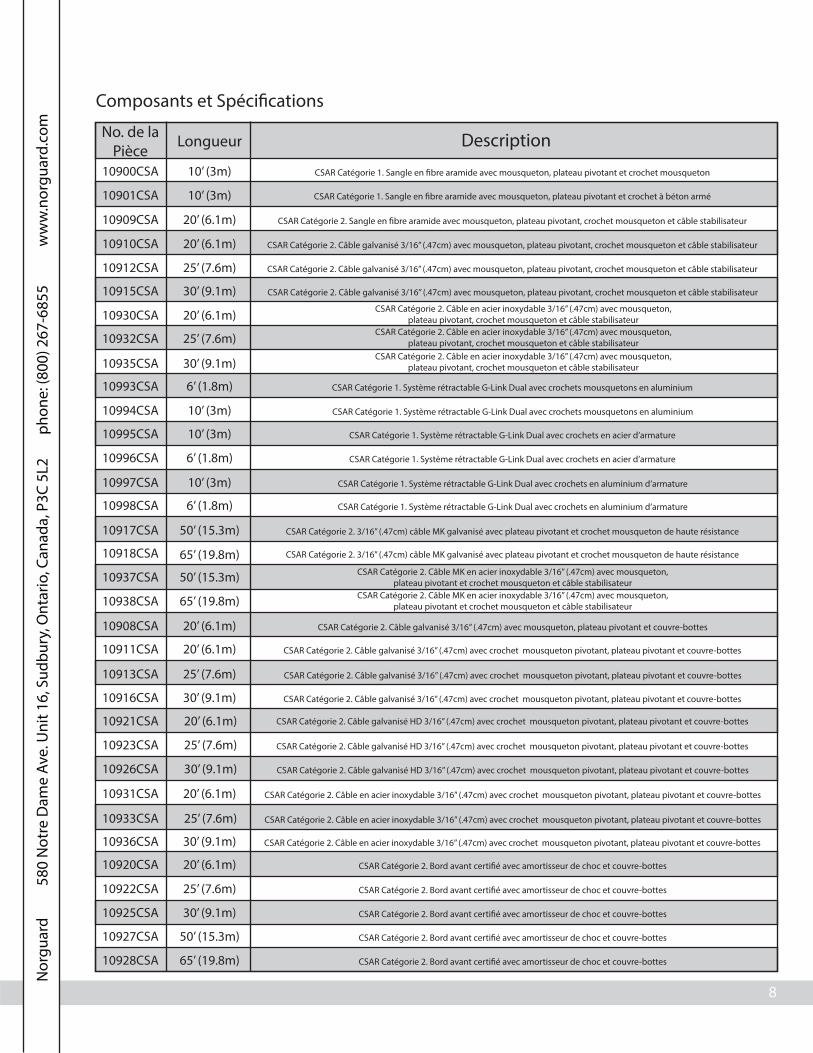
Composants et Spéci�cations
No. de laPièce
Longueur Description
10900CSA
10901CSA
10’ (3m)
10’ (3m)
CSAR Catégorie 1. Sangle en �bre aramide avec mousqueton, plateau pivotant et crochet mousqueton
CSAR Catégorie 1. Sangle en �bre aramide avec mousqueton, plateau pivotant et crochet à béton armé
10909CSA
10910CSA
10912CSA
20’ (6.1m)
20’ (6.1m)
25’ (7.6m)
CSAR Catégorie 2. Sangle en �bre aramide avec mousqueton, plateau pivotant, crochet mousqueton et câble stabilisateur
CSAR Catégorie 2. Câble galvanisé 3/16” (.47cm) avec mousqueton, plateau pivotant, crochet mousqueton et câble stabilisateur
CSAR Catégorie 2. Câble galvanisé 3/16” (.47cm) avec mousqueton, plateau pivotant, crochet mousqueton et câble stabilisateur
10915CSA
10932CSA
10930CSA
10935CSA
30’ (9.1m)
20’ (6.1m)
25’ (7.6m)
30’ (9.1m)
CSAR Catégorie 2. Câble galvanisé 3/16” (.47cm) avec mousqueton, plateau pivotant, crochet mousqueton et câble stabilisateur
CSAR Catégorie 2. Câble en acier inoxydable 3/16” (.47cm) avec mousqueton,plateau pivotant, crochet mousqueton et câble stabilisateur
10993CSA
10994CSA
10995CSA
10996CSA
10997CSA
10998CSA
6’ (1.8m)
10’ (3m)
10’ (3m)
6’ (1.8m)
10’ (3m)
6’ (1.8m)
CSAR Catégorie 1. Système rétractable G-Link Dual avec crochets mousquetons en aluminium
CSAR Catégorie 1. Système rétractable G-Link Dual avec crochets mousquetons en aluminium
CSAR Catégorie 1. Système rétractable G-Link Dual avec crochets en acier d’armature
CSAR Catégorie 1. Système rétractable G-Link Dual avec crochets en acier d’armature
CSAR Catégorie 1. Système rétractable G-Link Dual avec crochets en aluminium d’armature
CSAR Catégorie 1. Système rétractable G-Link Dual avec crochets en aluminium d’armature
10917CSA
10918CSA
10937CSA
10938CSA
50’ (15.3m)
65’ (19.8m)
50’ (15.3m)
65’ (19.8m)
CSAR Catégorie 2. 3/16” (.47cm) câble MK galvanisé avec plateau pivotant et crochet mousqueton de haute résistance
CSAR Catégorie 2. 3/16” (.47cm) câble MK galvanisé avec plateau pivotant et crochet mousqueton de haute résistance
CSAR Catégorie 2. Câble MK en acier inoxydable 3/16” (.47cm) avec mousqueton,plateau pivotant et crochet mousqueton et câble stabilisateur
10908CSA
10911CSA
10913CSA
10916CSA
10921CSA
10923CSA
10931CSA
10933CSA
10936CSA
20’ (6.1m)
20’ (6.1m)
25’ (7.6m)
30’ (9.1m)
20’ (6.1m)
25’ (7.6m)
20’ (6.1m)
25’ (7.6m)
30’ (9.1m)
10920CSA
10922CSA
10925CSA
10927CSA
10928CSA
20’ (6.1m)
25’ (7.6m)
30’ (9.1m)
50’ (15.3m)
65’ (19.8m)
CSAR Catégorie 2. Câble galvanisé 3/16” (.47cm) avec mousqueton, plateau pivotant et couvre-bottes
CSAR Catégorie 2. Câble galvanisé 3/16” (.47cm) avec crochet mousqueton pivotant, plateau pivotant et couvre-bottes
CSAR Catégorie 2. Câble galvanisé 3/16” (.47cm) avec crochet mousqueton pivotant, plateau pivotant et couvre-bottes
CSAR Catégorie 2. Câble galvanisé 3/16” (.47cm) avec crochet mousqueton pivotant, plateau pivotant et couvre-bottes
CSAR Catégorie 2. Câble en acier inoxydable 3/16” (.47cm) avec crochet mousqueton pivotant, plateau pivotant et couvre-bottes
CSAR Catégorie 2. Câble en acier inoxydable 3/16” (.47cm) avec crochet mousqueton pivotant, plateau pivotant et couvre-bottes
CSAR Catégorie 2. Câble en acier inoxydable 3/16” (.47cm) avec crochet mousqueton pivotant, plateau pivotant et couvre-bottes
CSAR Catégorie 2. Bord avant certi�é avec amortisseur de choc et couvre-bottes
CSAR Catégorie 2. Bord avant certi�é avec amortisseur de choc et couvre-bottes
CSAR Catégorie 2. Bord avant certi�é avec amortisseur de choc et couvre-bottes
CSAR Catégorie 2. Bord avant certi�é avec amortisseur de choc et couvre-bottes
CSAR Catégorie 2. Bord avant certi�é avec amortisseur de choc et couvre-bottes
10926CSA 30’ (9.1m)
CSAR Catégorie 2. Câble galvanisé HD 3/16” (.47cm) avec crochet mousqueton pivotant, plateau pivotant et couvre-bottes
CSAR Catégorie 2. Câble galvanisé HD 3/16” (.47cm) avec crochet mousqueton pivotant, plateau pivotant et couvre-bottes
CSAR Catégorie 2. Câble galvanisé HD 3/16” (.47cm) avec crochet mousqueton pivotant, plateau pivotant et couvre-bottes
CSAR Catégorie 2. Câble en acier inoxydable 3/16” (.47cm) avec mousqueton,plateau pivotant, crochet mousqueton et câble stabilisateur
CSAR Catégorie 2. Câble en acier inoxydable 3/16” (.47cm) avec mousqueton,plateau pivotant, crochet mousqueton et câble stabilisateur
CSAR Catégorie 2. Câble MK en acier inoxydable 3/16” (.47cm) avec mousqueton,plateau pivotant et crochet mousqueton et câble stabilisateur
N
orgu
ard
580
Not
re D
ame
Ave.
Uni
t 16,
Sud
bury
, Ont
ario
, Can
ada,
P3C
5L2
pho
ne: (
800)
267
-685
5
ww
w.n
orgu
ard.
com

9
Consulter le fabricant pour la composition de matériel spéci�que du modèle. Les CSAR fabriqués àpartir des de tous les composants suivants :Aluminium, acier galvanisé, acier inoxydable, nylon, polyester, et plastique ABS.
Connecteur (crochetmousquetonou crochet de
barre d’armature)
Point d’attachedu mousqueton
Emplacement ducordage de sécurité
Cordage desécurité
*Numéros de pièce(s) : 10917CSA, 10918CSA, 10937CSA, 10938CSA, 10974CSA, et 10981CSA ne sont pasactuellement disponible. Contactez Norguard pour plus de renseignements.
Part # Length Description
10946CSA
10950CSA
10’ (3m)
10’ (3m) CSAR Catégorie 1. Câble CSAR avec gaine jaune hautement résistant avec emballage de choc
CSAR Catégorie 1. Câble CSAR avec gaine jaune avec crochet mousqueton pivotant hautement résistant
10952CSA
10956CSA
10957CSA
10’ (3m)
10’ (3m)
10’ (3m)
CSAR Catégorie 1. Câble CSAR avec gaine jaune avec crochet en aluminium d’armature
CSAR Catégorie 1. Câble CSAR avec gaine jaune avec crochet mousqueton non indicatif hautement résistant
CSAR Catégorie 1. Câble CSAR avec gaine jaune avec crochet mousqueton indicatif hautement résistant
10974CSA
10984CSA
10981CSA
10985CSA
10987CSA
10989CSA
11009CSA
50’ (15.3m)
65’ (19.8m)
50’ (15.3m)
25’ (7.6m)
20’ (6.1m)
16’ (4.9m)
80’ (24.4m)
CSAR Catégorie 3. CSAR sauvetage/récupération en 3 façons de 3/16” (.47cm)
CSAR Catégorie 3. CSAR sauvetage/récupération en 3 façons de 3/16” (.47cm)
CSAR Catégorie 2. Câble galvanisé 3/16” (.47cm) avec plateau pivotant, crochet mousqueton pivotant et mousqueton
CSAR Catégorie 2. Câble galvanisé 3/16” (.47cm) avec plateau pivotant, crochet mousqueton pivotant et mousqueton
CSAR Catégorie 2. Câble galvanisé 3/16” (.47cm) avec plateau pivotant, crochet mousqueton pivotant et mousqueton
CSAR Catégorie 2. Câble galvanisé 3/16” (.47cm) avec plateau pivotant, crochet mousqueton pivotant et mousqueton
CSAR Catégorie 2. Câble galvanisé 3/16” (.47cm) avec plateau pivotant, crochet mousqueton pivotant et mousqueton
Exemple CSAR Norguard:
Exemple d’indicateur d’impact:• Vert: non déployé• Rouge: déployé
*L’amortisseur de choc quimontre des signes de
déploiement fonctionneaussi comme un
indicateur d’impact.
10910ARCSA 20’ (6.1m) CSAR Catégorie 2. Câble galvanisé 3/16” (.47cm) avec mousqueton, plateau pivotant,crochet mousqueton en aluminium et câble stabilisateur
10912ARCSA 25’ (7.6m)
10915ARCSA 30’ (9.1m)
CSAR Catégorie 2. Câble galvanisé 3/16” (.47cm) avec mousqueton, plateau pivotant,crochet mousqueton en aluminium et câble stabilisateur
CSAR Catégorie 2. Câble galvanisé 3/16” (.47cm) avec mousqueton, plateau pivotant,crochet mousqueton en aluminium et câble stabilisateur
N
orgu
ard
580
Not
re D
ame
Ave.
Uni
t 16,
Sud
bury
, Ont
ario
, Can
ada,
P3C
5L2
pho
ne: (
800)
267
-685
5
ww
w.n
orgu
ard.
com
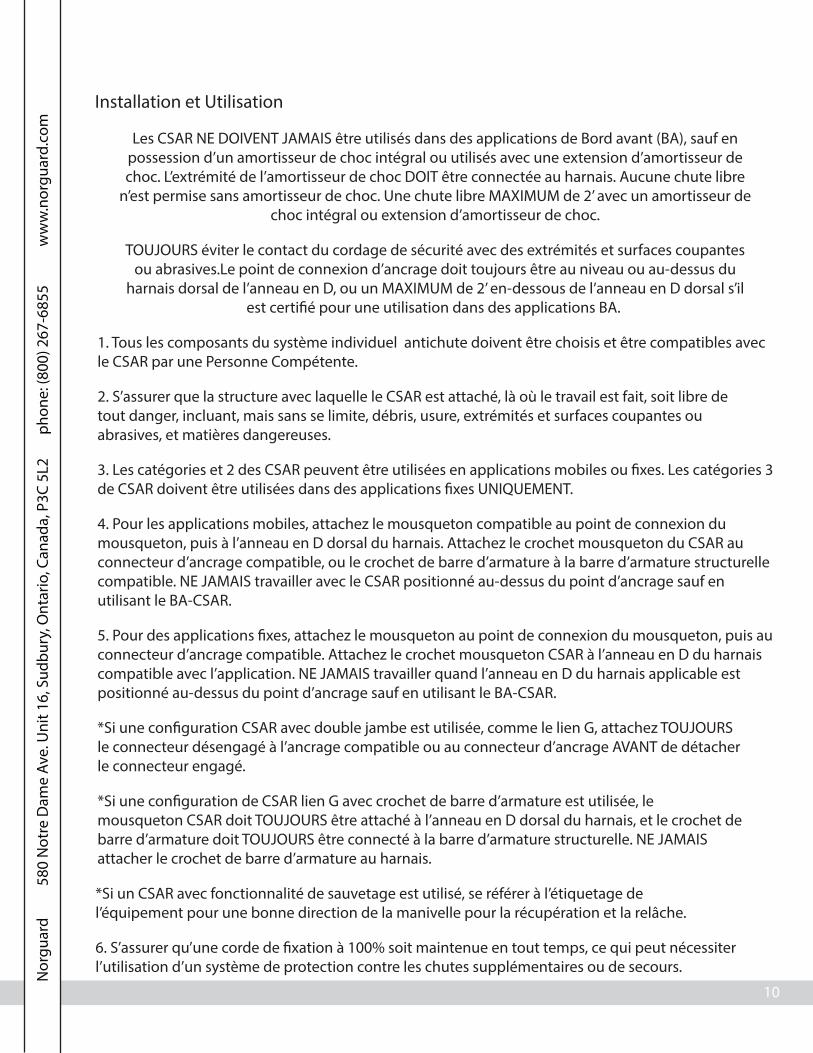
10
Installation et Utilisation
Les CSAR NE DOIVENT JAMAIS être utilisés dans des applications de Bord avant (BA), sauf enpossession d’un amortisseur de choc intégral ou utilisés avec une extension d’amortisseur dechoc. L’extrémité de l’amortisseur de choc DOIT être connectée au harnais. Aucune chute libre
n’est permise sans amortisseur de choc. Une chute libre MAXIMUM de 2’ avec un amortisseur dechoc intégral ou extension d’amortisseur de choc.
6. S’assurer qu’une corde de �xation à 100% soit maintenue en tout temps, ce qui peut nécessiterl’utilisation d’un système de protection contre les chutes supplémentaires ou de secours.
TOUJOURS éviter le contact du cordage de sécurité avec des extrémités et surfaces coupantesou abrasives.Le point de connexion d’ancrage doit toujours être au niveau ou au-dessus du
harnais dorsal de l’anneau en D, ou un MAXIMUM de 2’ en-dessous de l’anneau en D dorsal s’ilest certi�é pour une utilisation dans des applications BA.
1. Tous les composants du système individuel antichute doivent être choisis et être compatibles avecle CSAR par une Personne Compétente.
2. S’assurer que la structure avec laquelle le CSAR est attaché, là où le travail est fait, soit libre detout danger, incluant, mais sans se limite, débris, usure, extrémités et surfaces coupantes ouabrasives, et matières dangereuses.
3. Les catégories et 2 des CSAR peuvent être utilisées en applications mobiles ou �xes. Les catégories 3de CSAR doivent être utilisées dans des applications �xes UNIQUEMENT.
4. Pour les applications mobiles, attachez le mousqueton compatible au point de connexion dumousqueton, puis à l’anneau en D dorsal du harnais. Attachez le crochet mousqueton du CSAR auconnecteur d’ancrage compatible, ou le crochet de barre d’armature à la barre d’armature structurellecompatible. NE JAMAIS travailler avec le CSAR positionné au-dessus du point d’ancrage sauf enutilisant le BA-CSAR.
5. Pour des applications �xes, attachez le mousqueton au point de connexion du mousqueton, puis auconnecteur d’ancrage compatible. Attachez le crochet mousqueton CSAR à l’anneau en D du harnaiscompatible avec l’application. NE JAMAIS travailler quand l’anneau en D du harnais applicable estpositionné au-dessus du point d’ancrage sauf en utilisant le BA-CSAR.
*Si une con�guration CSAR avec double jambe est utilisée, comme le lien G, attachez TOUJOURSle connecteur désengagé à l’ancrage compatible ou au connecteur d’ancrage AVANT de détacherle connecteur engagé.
*Si une con�guration de CSAR lien G avec crochet de barre d’armature est utilisée, lemousqueton CSAR doit TOUJOURS être attaché à l’anneau en D dorsal du harnais, et le crochet debarre d’armature doit TOUJOURS être connecté à la barre d’armature structurelle. NE JAMAISattacher le crochet de barre d’armature au harnais.
*Si un CSAR avec fonctionnalité de sauvetage est utilisé, se référer à l’étiquetage del’équipement pour une bonne direction de la manivelle pour la récupération et la relâche.
N
orgu
ard
580
Not
re D
ame
Ave.
Uni
t 16,
Sud
bury
, Ont
ario
, Can
ada,
P3C
5L2
pho
ne: (
800)
267
-685
5
ww
w.n
orgu
ard.
com
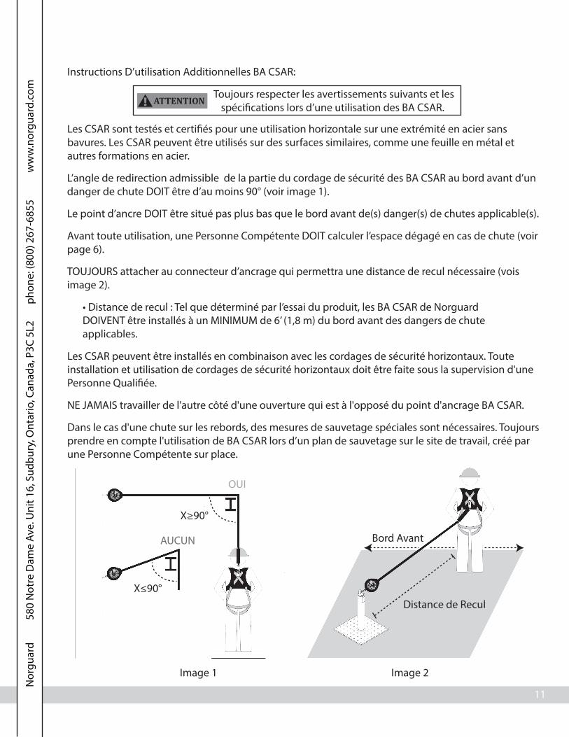
11
Instructions D’utilisation Additionnelles BA CSAR:
Les CSAR sont testés et certi�és pour une utilisation horizontale sur une extrémité en acier sansbavures. Les CSAR peuvent être utilisés sur des surfaces similaires, comme une feuille en métal etautres formations en acier.
L’angle de redirection admissible de la partie du cordage de sécurité des BA CSAR au bord avant d’undanger de chute DOIT être d’au moins 90° (voir image 1).
Le point d’ancre DOIT être situé pas plus bas que le bord avant de(s) danger(s) de chutes applicable(s).
Avant toute utilisation, une Personne Compétente DOIT calculer l’espace dégagé en cas de chute (voirpage 6).
Les CSAR peuvent être installés en combinaison avec les cordages de sécurité horizontaux. Touteinstallation et utilisation de cordages de sécurité horizontaux doit être faite sous la supervision d'unePersonne Quali�ée.
NE JAMAIS travailler de l'autre côté d'une ouverture qui est à l'opposé du point d'ancrage BA CSAR.
Dans le cas d'une chute sur les rebords, des mesures de sauvetage spéciales sont nécessaires. Toujoursprendre en compte l'utilisation de BA CSAR lors d’un plan de sauvetage sur le site de travail, créé parune Personne Compétente sur place.
Distance de Recul
Image 1 Image 2
Bord Avant
TOUJOURS attacher au connecteur d’ancrage qui permettra une distance de recul nécessaire (voisimage 2).
X≤90°
X≥90°
Toujours respecter les avertissements suivants et lesspéci�cations lors d’une utilisation des BA CSAR. ! ATTENTION
• Distance de recul : Tel que déterminé par l’essai du produit, les BA CSAR de NorguardDOIVENT être installés à un MINIMUM de 6’ (1,8 m) du bord avant des dangers de chuteapplicables.
AUCUN
OUI
N
orgu
ard
580
Not
re D
ame
Ave.
Uni
t 16,
Sud
bury
, Ont
ario
, Can
ada,
P3C
5L2
pho
ne: (
800)
267
-685
5
ww
w.n
orgu
ard.
com

13
Étiquettes
10900CSA, 10901CSA:
10909CSA, 10910CSA, 10912CSA, 10915CSA, 10930CSA, 10932CSA, 10935CSA, 10910ARCSA,10912ARCSA,10915ARCSA:
OSHA 1926.502, 1910.66ANSI Z359.14-2012, A10.32-2012
CSA Z259.2.2-98
SELF
-RETRACTING LIFELINE
J F M AA JM J S O N DYR
YR
YR
YR
YR
20’ 1” WEB6m 2.54cm TOILE
20’ 3/16” CABLE6m .47cm CABLE
25’ 3/16” CABLE7.6m .47cm CABLE
30’ 3/16” CABLE9.1m .47cm CABLE
Serial # / # de SérieLot # / # de Lot Mfg. Date / Date de Fabrication
10909CSA
ANSI Z359.14-2012, A10.32-2012OSHA 1926.502, 1910.66
CSA Z259.2.2-98
_____/_____Date of first use /
Date de la première utilisation
INSPECTION: Inspect unit in accordance to the manufacturer’s instruction manual and regulatory guidelines. Check lifeline retraction by pulling out a minimum 4 ft. of lifeline and allowing it to retract under light tension, lifeline should retract completely. Pull sharply to test locking function, brakes must engage. Before use, inspect the lifeline condition, function and condition of fasteners, and legibility of labels. Also, check for evidence of defects, damage or missing parts. User must inspect the impact indicator for signs of activation. Device must be taken out of
service after arresting a fall or if the impact indicator show signs of activation. / Appareil doit être mis hors service après avoir
arête une chute ou si l’indcateur d’impact montre des signes d’activation. Do not use if inspection reveals an unsafe condition. Unit must be inspected by a trained and Competent Person at least monthly. This device must be sent back to the manufacturer or an authorized service
center a maximum of 2 years after date of manufacture for recertification, and annually thereafter. / Cet appareil
doit être renvoyé au fabricant ou à un centre de service autorisé un maximum de 2 ans après la date de fabrication de l’inspection fabricant, et annuellement par la suite.
90063 (Rev. A)
SPECIFICATIONS:Class B SRLType 2 SRL / Catégorie 2Average arresting force: 900 lbs.Maximum arresting force: 1,800 lbs. / Force d’arrêt max: 816.4 kgMaximum arresting distance: 54 in. / Distance maximale d’arrêt: 137.1 cmCapacity Range: 130-310 lbs. / Plage de puissance: 58.9-140.6 kg
WARNING: Prior to use, fully read and understand all manufacturer’s instructions provided with equipment at time of
shipment. / Suivre toutes les instructions du fabricant incluses au moment de l’expédition. DO NOT ATTEMPT TO SELF
SERVICE OR REPAIR! DO NOT REMOVE THIS LABEL.
USE: Always use in accordance with manufacturer’s instruction manual and labels included with this device at the time of shipment.
This device is only for use by one person as a fall arrester. / Cet appareil doit uniquement êntre utilisê par une seule personne
comme un atichute. Always connect the snap hook directly to the attachment point on the safety harness. Guard against
swing-falls by keeping the lifeline vertically overhead. No free fall is allowed. SRL must always be positioned at or
above harness D-ring. Do not allow lifeline to come in contact with sharp or abrasive edges and surfaces.
Ensure that connection to anchorage is secured properly before use. May be used as a component of a PFAS in HLL applications. Design, installation, and utilization of HLLs must be supervised by a Qualified Person. Unsuitable for
horizontal use.
10910CSA (g)
10930CSA (ss)
10910ARCSA
10912CSA (g)
10932CSA (ss)
10915CSA (g)
10935CSA (ss)CUSTOMCOUTUME
10912ARCSA 10915ARCSA
OSHA 1926.502, 1910.66ANSI Z359.14-2012, A10.32-2012
CSA Z259.2.2-98
Max. arresting distance: 54 in / Distance maximale d’arrêt: 137.1 cmMax. arresting force: 1,800 lbs. / Force d'arrêt max: 816.4 kgCapacity Range: 130-310 lbs. / Plage de puissance: 58.9-140.6 kgAverage arresting force: 900 lbs.Type 1 SRL / Catégorie 1Class B SRL
WARNING: Prior to use,fully read and understand all manufacturer’s instructions
provided with equipment at time of shipment. / Suivre toutes les instructions du fabricant
incluses au moment de l’expédition. DO NOT ATTEMPT TO SELF SERVICE OR
REPAIR! DO NOT REMOVE THIS LABEL.
USE: Always use in accordance with manufacturer’s instruction manual and labels
included with this device at the time of shipment. This device is only for use by
one person as a fall arrester. / Cet appareil doit uniquement êntre utilisê par une seule
personne comme un atichute. Always connect the snap hook directly to the attachment point on the safety harness. Guard against swing-falls by keeping the
lifeline vertically overhead. No free fall is allowed. SRL must always be positioned at or above harness
D-ring. Do not allow lifeline to come in contact with sharp or abrasive edges and surfaces. Ensure that connection to anchorage is secured properly
before use. May be used as a component of a PFAS in HLL applications. Design, installation and utilization of HLLs must be supervised by a
Qualified Person. Unsuitable for horizontal use.
90062 (Rev. A)
_____/_____Date of first use /Date de la première utilisation
INSPECTION: Before use, inspect the lifeline condition, function and condition of fasteners, and legibility of labels. Also, check for evidence of defects, damage or missing parts. User must inspect the impact indicator for signs of activation. Check lifeline retraction by pulling out a minimum 4 ft. of lifeline and allowing it to retract under light tension, lifeline should retract completely. Pull sharply to test locking
function, brakes must engage. Device must be taken out of service after arresting a fall or if the
impact indicator show signs of activation. / Appareil doit être mis hors service après avoir arête une chute ou si l’indcateur d’impact montre des signes d’activation.
Inspection by a Competent Person required monthly.
Serial # / # de SérieLot # / # de Lot Mfg. Date / Date deFabrication
10' Nylon, 7/8" Width3m Nylon, 2.2cm Largeur
10900CSA 10901CSA
Front Back
Front
Back
N
orgu
ard
580
Not
re D
ame
Ave.
Uni
t 16,
Sud
bury
, Ont
ario
, Can
ada,
P3C
5L2
pho
ne: (
800)
267
-685
5
ww
w.n
orgu
ard.
com

14
10993CSA, 10994CSA, 10995CSA, 10996CSA, 10997CSA, 10998CSA:
10946CSA, 10950CSA, 10952CSA, 10956CSA, 10957CSA:
OSHA 1926.502, 1910.66ANSI Z359.14-2012, A10.32-2012
CSA Z259.2.2-98
Max. arresting distance: 54 in / Distance maximale d’arrêt: 137.1 cmMax. arresting force: 1,800 lbs. / Force d'arrêt max: 816.4 kgCapacity Range: 130-310 lbs. / Plage de puissance: 58.9-140.6 kgAverage arresting force: 900 lbs.Type 1 SRL / Catégorie 1Class B SRL
WARNING: Prior to use,fully read and understand all manufacturer’s instructions
provided with equipment at time of shipment. / Suivre toutes les instructions du fabricant
incluses au moment de l’expédition. DO NOT ATTEMPT TO SELF SERVICE OR
REPAIR! DO NOT REMOVE THIS LABEL.
USE: Always use in accordance with manufacturer’s instruction manual and labels
included with this device at the time of shipment. This device is only for use by
one person as a fall arrester. / Cet appareil doit uniquement êntre utilisê par une seule
personne comme un atichute. Always connect the snap hook directly to the attachment point on the safety harness. Guard against swing-falls by keeping the
lifeline vertically overhead. No free fall is allowed. SRL must always be positioned at or above harness
D-ring. Do not allow lifeline to come in contact with sharp or abrasive edges and surfaces. Ensure
that connection to anchorage is secured properly before use. May be used as a component of a PFAS
in HLL applications. Design, installation and utilization of HLLs must be supervised by a
Qualified Person. Unsuitable for horizontal use.
____/____Date of first use / Datede la première utilisation
INSPECTION: Before use, inspect the lifeline condition, function and condition of fasteners, and legibility of labels. Also, check for evidence of defects, damage or missing parts. User must inspect the impact indicator for signs of activation. Check lifeline retraction by pulling out a minimum 4 ft. of lifeline and allowing it to retract under light tension, lifeline should retract completely. Pull sharply to test locking
function, brakes must engage. Device must be taken out of service after arresting a fall or if the
impact indicator show signs of activation. / Appareil doit être mis hors service après avoir arête une chute ou si l’indcateur d’impact montre des signes d’activation.
Inspection by a Competent Person required monthly.
Serial # / # de SérieLot # / # de Lot
Mfg. Date / Datede Fabrication
6' Nylon, 7/8" Width / 1.8m Nylon, 2.2cm Largeur
10993CSA 10996CSA 10998CSA10' Nylon, 7/8" Width / 3m Nylon, 2.2cm Largeur
10994CSA 10995CSA 10997CSA
90064 (Rev. A)
Front Back
WARNING: Prior to use, fully read and understand all manufacturer’s
instructions provided with equipment at time of shipment. / Suivre toutes les
instructions du fabricant incluses au moment de l’expédition. DO NOT ATTEMPT TO
SELF SERVICE OR REPAIR! DO NOT REMOVE THIS LABEL.
USE: Always use in accordance with manufacturer’s instruction manual and labels
included with this device at the time of shipment. This device is only for use by one person as a fall
arrester. / Cet appareil doit uniquement êntre utilisê par une seule personne comme un atichute. Always
connect the snap hook directly to the attachment point on the safety harness. Guard against swing-falls by
keeping the lifeline vertically overhead. No free fall is allowed. SRL must always be positioned at or
above harness D-ring. Do not allow lifeline to come in contact with sharp or abrasive edges and
surfaces. Ensure that connection to anchorage is secured properly before use. May be used as a
component of a PFAS in HLL applications. Design, installation and utilization of HLLs
must be supervised by a Qualified Person.90067 (Rev. A)
INSPECTION: Before use, inspect the lifeline condition, function and condition of fasteners, and legibility of labels. Also, check for evidence of defects, damage or missing parts. User must inspect the impact indicator for signs of activation. Check lifeline retraction by pulling out a minimum 4 ft. of lifeline and allowing it to retract under light tension, lifeline should retract completely. Pull sharply to test locking function, brakes must engage. Device must be taken out of service after arresting a fall or if the impact indicator show signs of activation. / Appareil doit être mis hors service après avoir arête une chute ou si l’indcateur d’impact montre des signes d’activation. Inspection by a Competent Person required monthly.
SPECIFICATIONS:Maximum arresting distance: 54 in / Distance maximale d’arrêt: 137.1 cmMaximum arresting force: 1,800 lbs. / Force d'arrêt maximale: 816.4 kgCapacity range: 130-310 lbs. / Plage de puissance: 58.9-140.6 kgAverage arresting force: 900 lbs.Type 1 SRL / Catégorie 1Class B SRL
Serial # / # de SérieLot # / # de Lot
Mfg. Date / Date de Fabrication
10' 3/16" Cable / 3m .47cm Cable
10946CSA 10950CSA
10956CSA 10957CSA
10952CSA
____/____ Date of first use /Date de la première utilisation
OSHA 1926.502, 1910.66ANSI Z359.1, A10.32-2012,
CSA Z259.2.2-98
Front Back
N
orgu
ard
580
Not
re D
ame
Ave.
Uni
t 16,
Sud
bury
, Ont
ario
, Can
ada,
P3C
5L2
pho
ne: (
800)
267
-685
5
ww
w.n
orgu
ard.
com

15
10908CSA, 10911CSA, 10913CSA, 10916CSA, 10920CSA, 10922CSA, 10925CSA, 10927CSA, 10928CSA,10921CSA, 10923CSA, 10926CSA, 10931CSA, 10933CSA, 10936CSA:
OSHA 1926.502, 1910.66ANSI Z359.14-2012, A10.32-2012
CSA Z259.2.2-98
HEAV
Y D
UTY SELF-RETRACTING LIFELIN
E
25’ 3/16” CABLE7.6m .47cm CABLE
30’ 3/16” CABLE9.1m .47cm CABLE
50’ 3/16” CABLE15.3m .47cm CABLE
Serial # / # de SérieLot # / # de Lot Mfg. Date / Date de Fabrication
ANSI Z359.14-2012, A10.32-2012OSHA 1926.502, 1910.66
CSA Z259.2.2-98
J F M AA JM J S O N DYR
YR
YR
YR
YR
_____/_____Date of first use /
Date de la première utilisation
INSPECTION: Inspect unit in accordance to the manufacturer’s instruction manual and regulatory guidelines. Check lifeline retraction by pulling out a minimum 4 ft. of lifeline and allowing it to retract under light tension, lifeline should retract completely. Pull sharply to test locking function, brakes must engage. Before use, inspect the lifeline condition, function and condition of fasteners, and legibility of labels. Also, check for evidence of defects, damage or missing parts. User must inspect the impact indicator for signs of activation. Device must be taken out of
service after arresting a fall or if the impact indicator show signs of activation. / Appareil doit être mis hors service après avoir
arête une chute ou si l’indcateur d’impact montre des signes d’activation. Do not use if inspection reveals an unsafe condition. Unit must be inspected by a trained and Competent Person at least monthly. This device must be sent back to the manufacturer or an authorized service
center a maximum of 2 years after date of manufacture for recertification, and annually thereafter. / Cet appareil
doit être renvoyé au fabricant ou à un centre de service autorisé un maximum de 2 ans après la date de fabrication de l’inspection fabricant, et annuellement par la suite.
90065 (Rev. A)
SPECIFICATIONS:Class B SRLType 2 SRL / Catégorie 2Average arresting force: 900 lbs.Maximum arresting force: 1,800 lbs. / Force d’arrêt max: 816.4 kgMaximum arresting distance: 54 in. / Distance maximale d’arrêt: 137.1 cmCapacity Range: 130-310 lbs. / Plage de puissance: 58.9-140.6 kg
WARNING: Prior to use, fully read and understand all manufacturer’s instructions provided with equipment at time of
shipment. / Suivre toutes les instructions du fabricant incluses au moment de l’expédition. DO NOT ATTEMPT TO SELF
SERVICE OR REPAIR! DO NOT REMOVE THIS LABEL.
USE: Always use in accordance with manufacturer’s instruction manual and labels included with this device at the time of shipment.
This device is only for use by one person as a fall arrester. / Cet appareil doit uniquement êntre utilisê par une seule personne
comme un atichute. Always connect the snap hook directly to the attachment point on the safety harness. Guard against
swing-falls by keeping the lifeline vertically overhead. Maximum free fall 2' (.6m). Avoid lifeline contact with
sharp or abrasive edges and surfaces. Ensure that connection to anchorage is secured properly before use.
May be used as a component of a PFAS in HLL applications. Design, installation, and utilization of HLLs
must be supervised by a Qualified Person. Suitable for horizontal use. Competent Person must calculate adequate fall
clearance prior to use; refer to instructions for details. Minimum installation setback distance from leading edge is 6' (1.8 m).
10922CSA10908CSA
10913CSA
10923CSA
20’ 3/16” CABLE6m .47cm CABLE
20’ 1” NYLON6.1m 2.5cm NYLON
10920CSA
10911CSA
10925CSA
10916CSA
10927CSA65’ 3/16” CABLE
19.8m .47cm CABLE
10928CSA10926CSA
10933CSA
10921CSA
10931CSA 10936CSA CUSTOM / COUTUME
Front
Back
N
orgu
ard
580
Not
re D
ame
Ave.
Uni
t 16,
Sud
bury
, Ont
ario
, Can
ada,
P3C
5L2
pho
ne: (
800)
267
-685
5
ww
w.n
orgu
ard.
com

16
retractable
J F M AA JM J S O N DYR
YR
YR
YR
YR
_____/_____Date of first use /Date de la première utilisation
ANSI Z359.14-2012, A10.32-2012OSHA 1926.502, 1910.66 CSA Z259.2.2-98
16’ 3/16” CABLE4.9m .47cm CABLE
20’ 3/16” CABLE6.1m .47cm CABLE
25’ 3/16” CABLE7.7m .47cm CABLE
50’ 3/16” CABLE15.3m .47cm CABLE
Serial # / # de SérieLot # / # de Lot Mfg. Date / Date de Fabrication
10984CSA10989CSA 10985CSA 10987CSA
80’ 3/16” CABLE24.4m .47cm CABLE
11009CSA
WARNING: Prior to use, fully read and understand all manufacturer’s instructions provided with equipment
at time of shipment. / Suivre toutes les instructions du fabricant incluses au moment de l’expédition.DO NOT
ATTEMPT TO SELF SERVICE OR REPAIR! DO NOT REMOVE THIS LABEL!
USE: Always use in accordance with manufacturer’s instruction manual and labels included with this device at the time of
shipment. This device is only for use by one person as a fall arrester. / Cet appareil doit uniquement êntre utilisê par une
seule personne comme un atichute. Always connect the snap hook directly to the attachment point on the safety
harness. Guard against swing-falls by keeping the lifeline vertically overhead. No free fall is allowed. SRL must always be positioned at or above harness
D-ring. Do not allow lifeline to come in contact with sharp or abrasive edges and surfaces. Ensure that
connection to anchorage is secured properly before use. May be used as a component of a PFAS in HLL
applications. Design, installation, and utilization of HLLs must be supervised by a Qualified Person. Unsuitable for horizontal use.
INSPECTION: Inspect unit in accordance to the manufacturer’s instruction manual and regulatory guidelines. Check lifeline retraction by pulling out a minimum 4 ft. of lifeline and allowing it to retract under light tension, lifeline should retract completely. Pull sharply to test locking function, brakes must engage. Before use, inspect the lifeline condition, function and condition of fasteners, and legibility of labels. Also, check for evidence of defects, damage or missing parts. User must inspect the impact indicator for signs of activation. Device must be taken out of
service after arresting a fall or if the impact indicator show signs of activation. / Appareil doit être mis hors service
après avoir arête une chute ou si l’indcateur d’impact montre des signes d’activation. Do not use if inspection reveals an unsafe condition. Unit must be inspected by a trained and Competent Person at least monthly. This device must be sent back to the manufacturer or an
authorized service center a maximum of 2 years after date of manufacture for recertification, and annually
thereafter. / Cet appareil doit être renvoyé au fabricant ou à un centre de service autorisé un maximum de 2 ans après la date
de fabrication de l’inspection fabricant, et annuellement par la suite.
SPECIFICATIONS:Type 2 SRL / Catégorie 2Class B SRLAverage arresting force: 900 lbs.Maximum arresting force: 1,800 lbs. / Force d’arrêt max: 816.4 kgMaximum arresting distance: 54 in. / Distance maximale d’arrêt: 137.1 cmCapacity range: 130-310 lbs. / Plage de puissance: 58.9-140.6 kg
90068 (Rev. A)
10984CSA, 10985CSA, 10987CSA, 10989CSA, 11009CSA:
Front
Back
N
orgu
ard
580
Not
re D
ame
Ave.
Uni
t 16,
Sud
bury
, Ont
ario
, Can
ada,
P3C
5L2
pho
ne: (
800)
267
-685
5
ww
w.n
orgu
ard.
com

17
Journal D'inspection
Remarques
Si l'équipement échoue l'inspection, METTEZ-LE IMMÉDIATEMENT HORS SERVICE
L'utilisateur doit inspecter avant CHAQUE utilisation. La personne Compétente doit compléterune inspection formelle au moins TOUS les mois. Une Personne Compétente doit inspecter etinscrire ses initiales dans le journal d'inspection et l'étiquette d'inspection du CSAR.
Date de la première utilisation : __________________. Tant que le CSAR passe les inspectionsde pré-utilisation et de la personne Compétente et est recerti�é selon ce mode d'emploi, ladurée de vie des CSAR avec un cordage de sécurité à sangle est de 5 ans à partir de la date dela première utilisation, ou à partir de la date de la fabrication si la date de la premièreutilisation n'est pas enregistrée. La durée de vie des CSAR qui possèdent un câble de cordagede sécurité est indé�nie
Ce journal d'inspection doit être spéci�que à un CSAR. Les journaux d'inspection séparésdoivent être utilisés pour chaque CSAR. Tous les enregistrements d'inspection doivent êtrevisibles et disponibles à tous les utilisateurs en tout temps.
N
orgu
ard
580
Not
re D
ame
Ave.
Uni
t 16,
Sud
bury
, Ont
ario
, Can
ada,
P3C
5L2
pho
ne: (
800)
267
-685
5
ww
w.n
orgu
ard.
com