norbord inc. | an international producer of wood-based panels. · materials) give scientific...
TRANSCRIPT

Moisture-Resistant Wall Construction
B U I L D A B E T T E R H O M E

A few facts about wood:We’re growing more wood every day. For the
past 100 years, the amount of forestland in the United
States has remained stable at a level of about 751 mil-
lion acres.1 Forests and wooded lands
cover over 40 percent of North America’s
land mass.2 Net growth of forests has
exceeded net removal since 19523; in
2011, net forest growth was measured
at double the amount of resources
removed.4 American landowners plant
more than two-and-a-half billion new
trees every year.5 In addition, millions
of trees seed naturally.
Manufacturing wood is energy efficient. Over 50 percent of the energy
consumed in manufacturing wood prod-
ucts comes from bioenergy such as tree
bark, sawdust, and other harvesting
by-products.6 Very little of the energy
used to manufacture engineered wood
comes from fossil fuels. Plus, modern methods allow
manufacturers to get more out of each log, ensuring
that very little of the forest resource is wasted.
Life Cycle Assessment measures the long-term green value of wood. Studies by CORRIM
(Consortium for Research on Renewable Industrial
Materials) give scientific validation to the strength
of wood as a green building product. In examining
building products’ life cycles—from
extraction of the raw material to dem-
olition of the building at the end of its
long lifespan—CORRIM found that
wood had a more positive impact on
the environment than steel or concrete
in terms of embodied energy, global
warming potential, air emissions, water
emissions and solid waste production.
For the complete details of the report,
visit www.CORRIM.org.
Wood adds environmental value throughout the life of a structure. When the goal is energy-eff icient
construction, wood’s low thermal con-
ductivity makes it a superior material.
As an insulator, wood is six times more
efficient than an equivalent thickness of brick, 105
times more efficient than concrete, and 400 times
more efficient than steel.7
Good news for a healthy planet. For every ton
of wood grown, a young forest produces 1.07 tons of
oxygen and absorbs 1.47 tons of carbon dioxide.
Wood is the natural choice for the environment, for design, and for strong, resilient construction.
Wood: The Natural ChoiceEngineered wood products are among the most beautiful and environmentally friendly building materials. In manufacture, they are produced efficiently from a renewable resource. In construction, the fact that engineered wood products are available in a wide variety of sizes and dimensions means there is less jobsite waste and lower disposal costs. In completed buildings, engineered wood products are carbon storehouses that deliver decades of strong, dependable structural performance. Plus, wood’s natural properties, combined with highly efficient wood-frame construction systems, make it a top choice in energy conservation.
1. United States Department of Agriculture, U.S. Forest Service, FS-979, June 2011; 2. FAO, UN-ECE (1996) North American Timber Trends Study. ECE/TIM/SP/9. Geneva; Smith et al. (1994), Forest Statistics of the United States, 1992. Gen. Tech. Rep. NC-168; 3. United States Department of Agriculture, U.S. Forest Service; FS-801 Revised September 2009; 4. U.S. Department of Agriculture, U.S. Forest Service, August 2014; 5. Forest Landowners Association, 2011; 6. U.S. Environmental Protection Agency, March 2007; 7. Produced for the Commonwealth of Australia by the Institute for Sustainable Futures, University of Technology, Sydney, 2010.
30
25
20
15
10
5
01952
Net Forest Growth
Resources Removed
2011
U.S. Forest Growth and All Forest Product Removals
Billions of cubic feet/year
Source: USDA—Forest Service
Wood-TheNaturalChoice-final.indd 1 8/11/2016 9:58:22 AM

Built-In Protection from Moisture IntrusionThe Build a Better Home program from APA provides builders and
homeowners with construction guidelines that protect homes against
damaging moisture infiltration. Preventing moisture from getting
trapped inside the building envelope is key to constructing long-
lasting homes that stay dry and comfortable.
Walls are an integral part of this weather-resistive system. Designing
and constructing wall details correctly, particularly around window
and door openings, can prevent harmful moisture build-up whether
the moisture originates from outside or inside the building.
This publication outlines the two primary sources of moisture in
wood wall construction and methods to prevent its accumula-
tion. Other design factors not covered in this publication include
insulation options and other energy considerations and design rec-
ommendations for buildings within flood zones. Check with your
local building department for these and other requirements specific
to your location.
Form No. A530C ■ © 2016 APA – The Engineered Wood Association ■ www.apawood.org 3
Build a Better Home: Moisture-Resistant Wall Construction

AVOIDING MOISTURE ACCUMULATION IN WALLS
Water can accumulate in walls from two
sources: water leaks and vapor-laden air that
penetrates the wall to produce condensa-
tion. Water from leaks presents the greatest
threat of water accumulation in walls. Since
water can leak directly into the wall, it
can quickly accumulate to levels that will
degrade the wood components as well as
other products in the wall. Moisture vapor
from air penetration and vapor diffusion are
important, but they represent much smaller
amounts of water accumulation.
HOW WATER LEAKS
INTO WOOD WALL
CONSTRUCTION
Water leaking through the envelope of a
structure is the largest contributor to build-
ing damage. Leaks are caused by a number
of factors, including:
■ Improper or missing flashing
■ Improper installation of water-resistive
barriers
■ Poorly designed or executed wall
intersections and penetrations
Wood structures have the ability to absorb,
distribute and dissipate small amounts of
water, especially from intermittent sources.
Problems arise when there are design or
construction errors that allow water into
wall cavities at a rate that exceeds the struc-
ture’s ability to absorb and dissipate the
water by evaporation. Wood construction
will perform indefinitely if done properly,
but it is subject to failure if exposed to pro-
longed wetting where the wood moisture
content exceeds 19 percent.
The control of water leaks into walls involves proper design, construction and maintenance. Design features
such as roof overhangs can provide moisture protection. Proper construction incorporates products like flashing,
water-resistant barriers, and caulks with the structural and architectural components in such a way that water is
deflected or drained down and away from the wall. Proper maintenance of caulks and paint is necessary for long-
term moisture performance of walls.
Window sill with flange
Pan flashing (or self-adhered flashing)
Wood structural panel sheathing
Caulking/sealant with backer rod
Drip edge
Pan flashing (or self-adhered flashing)
Water-resistive barrier—lap over top of metal head flashing
Wood siding
Metal head flashing
Self-adhered flashing
Sloped top and drip-edged head trim
Caulking/sealant with backer rod
Sealant
Window flange
Water-resistive barrier
Wood structural panel sheathing
Wood siding
FIGURE 1
CROSS-SECTION OF WINDOW OPENING SHOWING INTEGRATION OF STRUCTURE’S WATER-RESISTIVE SYSTEM IN A WALL WITH WOOD SIDING
Form No. A530C ■ © 2016 APA – The Engineered Wood Association ■ www.apawood.org 4
Build a Better Home: Moisture-Resistant Wall Construction

PREVENTING LEAKS WITH FLASHING
Flashing is used to deflect water and thus prevent leaks around wall intersections, window and door openings,
and penetrations. Flashing can be made from galvanized steel, copper, aluminum, lead, vinyl, cut strips of
water-resistive barrier materials, or various self-adhered membrane flashing products. At small wall penetrations,
such as exhaust vents, custom flashing is used in lieu of conventional flashing because of the irregular shapes.
Flashing directs water flow down and away from the interior of the structure to the outside of the wall covering. In
every example shown here, the water-resistive barrier laps over the top edge of the flashing. In such a manner, the
flashing is part of a whole water-resistive system that is continuously redirecting water flow down and away from
the interior of the structure.
Figures 1 through 16 illustrate examples of typical flashing details for wood-framed walls with various exterior finishes.
WATER-RESISTIVE BARRIERS
Long-term durability of wood-framed walls
depends largely on keeping water out of the
wall cavity. In order to accomplish this, a pro-
tective weather- or water-resistive barrier (i.e.,
building paper), or an approved alternative,
such as “house wrap” that also sheds water is
needed. (In this publication, weather-resistive
barriers and house wrap are generally referred
to as water-resistive barriers.)
Water-resistive barrier materials provide a line
of defense for the building envelope against
the intrusion of water. The materials and
labor costs associated with these products
provide inexpensive protection for structural
components and reduce the risk of moisture
accumulation and damage to moisture-
sensitive materials such as wood sheathing
and studs. The barriers must be installed
properly, however, to prevent water leaks
into the wall cavity. Proper installation at
corners and intersections and incorporation of
flashing are particularly important.
The basic principle behind water-resistive
barrier materials is to provide a continuous
drainage plane that sheds moisture down and
away from the plane of the structural wall
surface. This is accomplished by overlapping
successive layers of water-resistive barrier
behind the exterior finish and over the
structural sheathing. In conjunction with
properly applied f lashing, water-resistive
FIGURE 2
FLASHING WINDOW WHEN USING WATER-RESISTIVE BARRIER
Apply water-resistivebarrier and cut modied
Apply sill ashingand window sealant
Create windowopening
Install window and apply jamb ashing
Apply headashing
Fold water-resistivebarrier down and tape over cuts
Note: In the case of single-wall construction consisting of siding applied direct to studs or over nonstructural sheathing, it may be necessary to attach the windows to the outside of the building. In such instances, refer to the manufacturer’s recommended installation procedures.
Form No. A530C ■ © 2016 APA – The Engineered Wood Association ■ www.apawood.org 5
Build a Better Home: Moisture-Resistant Wall Construction

barriers direct leakage away from the wood
structural panel sheathing. This principle also
extends to wall penetrations, such as windows
and doors, plumbing hose bibs, electrical
boxes, wall-mounted air conditioners and
vents for appliances, and at junctures with
horizontal surfaces such as exterior decks and
cantilevered balconies, or sloping roof-to-wall
surfaces. It is especially important in these
cases to ensure that water leaks are not directed
down the sheathing onto structural elements
below, or into the wall cavity.
Figures 1 through 16 illustrate how the
water-resistive barrier materials and flashing
work together to channel any water running
down the outside face of the barrier over the
flashing and outside of the envelope.
Wall Intersections and PenetrationsThere are many types of penetrations, including
dryer vents, bathroom exhaust fans, exterior
electrical outlets, exterior lights, and gas lines.
The unique construction detailing around these
penetrations requires special attention, including
details around the following:
■ Deck to wall intersections
■ Wall to roof intersections
■ Gutter to roof or wall intersections
■ Skylight installation
Figures 10 and 11 illustrate typical wall
intersection details. Figures 12 and 13 show a
common wall penetration detail using a water-
resistive barrier. Figure 14 shows a common
wall penetration detail using flashing and building paper. Figure 15 is an example of the detailing required at the intersection
of an outside deck and an exterior wall. Figure 16 shows the flashing and use of building paper around a door opening.
CAULKING AS A WATERPROOFING COMPONENT
Elastomeric exterior sealants, known as caulks, are a popular component of the waterproofing system used in
modern structures. Used to seal the cracks between individual elements of the building’s exterior finish, caulks
help keep wind and water from penetrating the skin of the structure. Caulks are never perfect, even when carefully
installed. However, caulks can be used as a secondary or tertiary part of the water-protective system.
Caulks are not permanent. They have a limited lifetime and must be replaced on a periodic basis. As a result, a caulked
joint cannot be the sole form of waterproofing at a given location. Intelligent building design, the use of back-up methods
of waterproofing such as building paper or “house wrap,” and proper placement of flashing should always be used in
conjunction with caulked joints.
FIGURE 3
FLASHING WINDOW WHEN USING BUILDING PAPER
Note: In the case of single-wall construction consisting of siding applied direct to studs or over nonstructural sheathing, it may be necessary to attach the windows to the outside of the building. In such instances, refer to the manufacturer’s recommended installation procedures.
Form No. A530C ■ © 2016 APA – The Engineered Wood Association ■ www.apawood.org 6
Build a Better Home: Moisture-Resistant Wall Construction
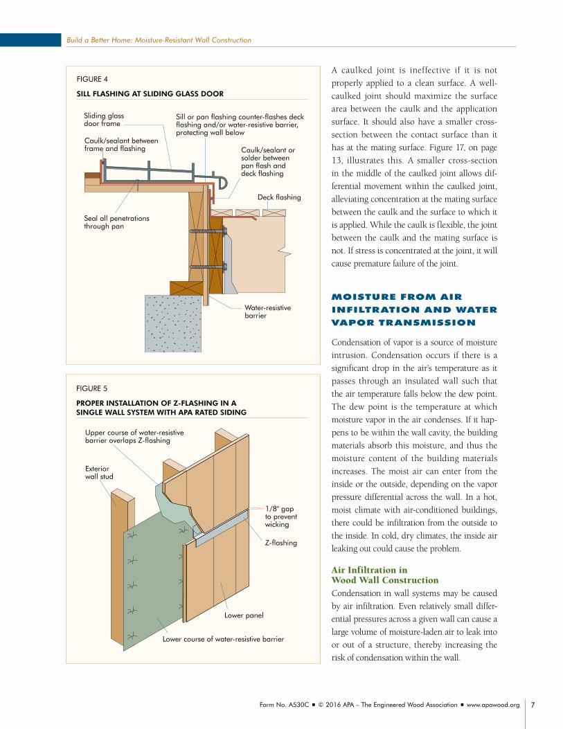
FIGURE 4
SILL FLASHING AT SLIDING GLASS DOOR
FIG 14.17
Deck flashing
Caulk/sealant orsolder betweenpan flash and deck flashing
Sill or pan flashing counter-flashes deck flashing and/or water-resistive barrier, protecting wall below
Caulk/sealant betweenframe and flashing
Seal all penetrationsthrough pan
Water-resistivebarrier
Sliding glass door frame
FIGURE 5
PROPER INSTALLATION OF Z-FLASHING IN A SINGLE WALL SYSTEM WITH APA RATED SIDING
FIG 14.18
1/8" gap to prevent wicking
Exteriorwall stud
Lower course of water-resistive barrier
Lower panel
Z-flashing
Upper course of water-resistive barrier overlaps Z-flashing
A caulked joint is ineffective if it is not
properly applied to a clean surface. A well-
caulked joint should maximize the surface
area between the caulk and the application
surface. It should also have a smaller cross-
section between the contact surface than it
has at the mating surface. Figure 17, on page
13, illustrates this. A smaller cross-section
in the middle of the caulked joint allows dif-
ferential movement within the caulked joint,
alleviating concentration at the mating surface
between the caulk and the surface to which it
is applied. While the caulk is flexible, the joint
between the caulk and the mating surface is
not. If stress is concentrated at the joint, it will
cause premature failure of the joint.
MOISTURE FROM AIR
INFILTRATION AND WATER
VAPOR TRANSMISSION
Condensation of vapor is a source of moisture
intrusion. Condensation occurs if there is a
significant drop in the air’s temperature as it
passes through an insulated wall such that
the air temperature falls below the dew point.
The dew point is the temperature at which
moisture vapor in the air condenses. If it hap-
pens to be within the wall cavity, the building
materials absorb this moisture, and thus the
moisture content of the building materials
increases. The moist air can enter from the
inside or the outside, depending on the vapor
pressure differential across the wall. In a hot,
moist climate with air-conditioned buildings,
there could be infiltration from the outside to
the inside. In cold, dry climates, the inside air
leaking out could cause the problem.
Air Infiltration in Wood Wall ConstructionCondensation in wall systems may be caused
by air infiltration. Even relatively small differ-
ential pressures across a given wall can cause a
large volume of moisture-laden air to leak into
or out of a structure, thereby increasing the
risk of condensation within the wall.
Form No. A530C ■ © 2016 APA – The Engineered Wood Association ■ www.apawood.org 7
Build a Better Home: Moisture-Resistant Wall Construction

FIGURE 7
CROSS-SECTION OF WINDOW SHOWING INTEGRATION OF STRUCTURE’S WATER-RESISTIVE SYSTEM IN A WALL WITH PORTLAND CEMENT STUCCO EXTERIOR WALL COVERING
Flashing over drip cap
Two layers of Grade D building paper or equivalent
Stucco
Sealant
Flashing under sill
Stucco
Two layers of Grade D building paper or equivalent
Metal lath
Metal lath
Wood structural panel
Wood structural panel
Note: Metal lath and water-resistive barrier must extend down over flashing.
Window
Window
FIGURE 6
CROSS-SECTION OF WINDOW SHOWING INTEGRATION OF STRUCTURE’S WATER-RESISTIVE SYSTEM IN A WALL WITH BRICK VENEER
Water-resistive barrier
Air gap
Wood structuralpanel
Through-wallflashing (installedbefore window)
Sealant
Water-resistive barrier
Air gap
Through-wallflashing
Self-adhered flashing
Steel lintel
Sealant
Weep holes
1" min.
Weep holes
Window
Window
Wood structuralpanel sheathing
Form No. A530C ■ © 2016 APA – The Engineered Wood Association ■ www.apawood.org 8
Build a Better Home: Moisture-Resistant Wall Construction

Air Infiltration BarriersDifferential air pressures across the wall
assembly can cause air infiltration. This
differ ential air pressure can be caused by an
unbalanced ventilation system, the stack effect
caused by hot air rising within the structure,
the use of unvented heating appliances,
or wind. The actual differen tial pressure
does not have to be very large to cause a
significant amount of air leakage in one
direction or another. If the moisture-laden
airflow persists for a significant length of time,
condensation buildup can cause moisture
damage to the structure and degrade the living
conditions therein.
An air infiltration barrier such as house wrap
can reduce the flow of moisture-laden air into
the wall cavity if installed properly. The air
barrier can be placed on the inside or outside
surface of the wall. In a cold climate that
requires a warm-side vapor retarder, the vapor
retarder may act as the air barrier as well, if
properly applied and sealed.
Because the major model building codes
allow air barriers to be used in lieu of building
paper for most applications, the use of these
products is on the rise. To get the full benefits
of an air barrier, it must be sealed as described
below to ensure that it is airtight.
Air barriers are available in rolls up to 9
feet wide, allowing the builder to wrap the
barrier all the way around the house dur-
ing construction. This is the origin of the
term “house wrap.” The large size speeds up
installation and minimizes the number of
seam seals. When the wrap is used as an air
barrier, all of the splits, seams, penetrations
and damaged areas must be repaired using a
special adhesive-backed seam tape.
Figure 18, on page 13, shows general
installation techniques for proper application
of an air barrier.
FIGURE 8
FLASHING AND WATER-RESISTIVE BARRIER INSTALLATION AT BRICK LEDGE
Water-resistive barrier
Brick tie
Wood structuralpanel
Weep holes
Air space (1" typical)
Treated lumber
Base flashing
FIGURE 9
FLASHING INSTALLATION AT TERMINATION OF PORTLAND CEMENT STUCCO EXTERIOR WALL COVERING
Where wood contacts stucco, cover with two layers of Grade D building paper or equivalent
Flashing
Grade
Note: Metal lath and building paper must extend down over flashing.
Wood structural panel
Metal lath
Treated lumber
Form No. A530C ■ © 2016 APA – The Engineered Wood Association ■ www.apawood.org 9
Build a Better Home: Moisture-Resistant Wall Construction

FIGURE 12
INTEGRATION OF STRUCTURE’S WATER-RESISTIVE SYSTEM AT A TYPICAL WALL PENETRATION
FIGURE 13
INTEGRATION OF STRUCTURE’S WATER-RESISTIVE SYSTEM AT A TYPICAL WALL PENETRATION WITH PRODUCTS THAT HAVE FLANGES
FIGURE 11
FLASHING INSTALLATION AT PORTLAND CEMENT STUCCO-TO-ROOF INTERSECTION
Base flashing
Roofing androof deck
Counter flashing
Metal lath
Wood structuralpanel
Two layers of Grade D building paper or equivalent
Note: Metal lath and weather-resistive barrier must extend down over flashing.
FIGURE 10
FLASHING INSTALLATION AT BRICK VENEER-TO-ROOF INTERSECTION
Counter flashing
Base flashing
Air space (1" typical)
Water-resistive barrier
Roofing and roof deck
Brick tie
Wood structural panel
Note: Sheathing not shown for clarity.
Flexible membrane
flashing
Tape
Water-resistivebarrier
Note: Sheathing not shown for clarity.
6" Minimum overlap
Self-adheredmembrane
flashing
Water-resistivebarrier
Tape
Note: Seal the water-resistive barrier around all electrical, HVAC, and plumbing penetrations. Start taping or flashing
at bottom of penetrations, shingling upper tape over bottom tape.
Form No. A530C ■ © 2016 APA – The Engineered Wood Association ■ www.apawood.org 10
Build a Better Home: Moisture-Resistant Wall Construction

Vapor Transmission in Wood Wall ConstructionVapor transmission is the molecular passage of water through the components of a building. A differential water
vapor pressure across the wall causes this movement. In cold weather, vapor from the interior of the structure can
permeate through the interior wall finish and condense on cooler framing and sheathing surfaces in the wall cavity
if there are surfaces colder than the dew point temperture. To prevent this, an effective interior (“warm side”) vapor
retarder installed beneath the interior wall finish or insulated sheathing is recommended by codes for most cold
climate regions.
The “warm side” vapor retarder in exterior walls may be omitted in regions with moderate temperatures, such as
the southern and southeastern United States. In warm, humid regions close to the Gulf of Mexico, in Hawaii, and
in the Caribbean regions where air conditioning is prevalent, the vapor retarder should be installed on the exterior
side of the wall behind the sheathing. This will prevent humid air from penetrating into the wall cavity and causing
increased condensation on the cooler interior wall surface.
Selection and Installation of Vapor RetarderWhen the warm side is determined to be the inside wall, the vapor retarder can be kraft paper or foil/kraft paper
facing on the wall insulation. The effectiveness of this vapor retarder depends on how carefully the insulation is
installed. The most effective installation technique is to cut the insulation batt length slightly oversize so it can be
friction-fit to avoid gaps at the top and bottom wall plates. Also, the installation tabs of the insulation facing should
be lapped and stapled onto the nailing surface of the studs instead of the sides of the studs to “seal” the insulation
facing against air and moisture leakage and to minimize gaps between the insulation and studs.
FIGURE 14
INTEGRATION OF STRUCTURE’S WEATHER-RESISTIVE SYSTEM AT A TYPICAL WALL PENETRATION
Water-resistive barrieroverlaps flashing
Water-resistive barrier under flashing
Nail first piece of flashing at top
Set second piece of flashing in caulking
2" overlap
3"
6"
Nail second flashing piece at top
Note: Sheathing not shown for clarity.
Form No. A530C ■ © 2016 APA – The Engineered Wood Association ■ www.apawood.org 11
Build a Better Home: Moisture-Resistant Wall Construction

FIGURE 16
PROPER INSTALLATION OF BUILDING PAPER—SHOWN AROUND A DOOR OPENING
6" min. vertical laps of building paper
Horizontal laps of building paper (2" min.) 4"–6" recommended3rd course
of building paper
Sealant betweenflashing andbuilding paper
Install successive layers of building paper“shingle-lap” layers starting at bottom and proceeding to top of wall
2nd course of building paper
1st course of building paper
Flashing
Flashing under building paper; Seal to sheathing
FIGURE 15
WATER-RESISTIVE SYSTEM AT AN EXTERIOR DECK
1/2" diameter lag screws or thru-bolts with washers
Exterior sheathing
Water-resistive barrier
Existing stud wall
Rim Board
Wood I-joist
2" min.
2" min.
1-5/8" min.5" max.
Existing foundation wall
Remove siding at ledger prior to installation
Continuous flashing extending at least 3" past joist hanger
Deck joist
Joist hanger
Self-adhered bituminous membrane
2x ledger board (preservative-treated);must be greater than or equal to the depth of the deck joist
Floor sheathing
Leave 3/4" gap betweenbottom of siding and top of deck
Form No. A530C ■ © 2016 APA – The Engineered Wood Association ■ www.apawood.org 12
Build a Better Home: Moisture-Resistant Wall Construction

Alternatively, an effective continuous vapor
retarder can be installed by using a separate
layer of 4-mil polyethylene sheeting stapled
over the interior side of the wall framing.
In this case, unfaced insulation without
an integral vapor retarder facing may be
used and friction-fit to fill the stud cavities
without gaps. While polyethylene sheeting
makes a very good vapor retarder, it is
relatively difficult to install. In most cases,
the use of polyethylene is not necessary
even in very cold regions. Ordinary interior
latex paint applied over drywall can provide
sufficient vapor retardant properties.
FIGURE 18
PROPER AIR BARRIER INSTALLATION DETAILS TWO-STORY WALL SHOWN (not to scale)
6"–12" overlap at corner and vertical joints
Upper roll overlapsbottom by 6"
2"–3" overlap at sill plate/foundation
Cut air barrier andwrap around sill and sides of window opening
6"–12" overlap at allhorizontal joints
Tape all tears and holes
Attach per manufacturer’srecommendations
Tape all joints withair-barrier tape
Wood structural panel
FIGURE 17
CAULKED JOINT GEOMETRY
Backer rod
Hour-glass caulk profile
Fillet caulk profile
Form No. A530C ■ © 2016 APA – The Engineered Wood Association ■ www.apawood.org 13
Build a Better Home: Moisture-Resistant Wall Construction

INSTALLING RAIN-SCREEN WALLS
The entire exterior finish, weather-proofing,
and flashing system in wood construction
relies on gravity to keep bulk water out of the
building envelope. Wind-driven rain can com-
promise these safeguards because the water
is hitting the wall from a different angle. If
wind-driven rain is an infrequent occurrence,
the forgiving nature of wood construction can
often account for the occasional influx of water
into the building system. The moisture will be
removed through capillary suction and evapo-
ration and the entire building frame will dry.
In areas where wind-driven rain is frequent,
the amount of water driven into the wall
system could be more damaging. In these
cases, a rain-screen wall is often used. Rain-
screen wall construction creates an air space
between the exterior finish system and the
weather-resistive system. This separation is
made with the use of pressure-treated lumber
spacers that are installed vertically and
carefully detailed around openings and
penetrations to allow drainage of any water
that makes it through the exterior finish. This
space—3/4 to 1 inch—is open at the bottom
to allow the air space to equalize with the
exterior air pressure. The top is trimmed out
to allow for air flow while preventing wind-
driven rain from getting behind the screen.
The openings at the top and bottom have pest
screens. This system is often used with an
interior air barrier to allow the air pressure in
the interior of the wall to equalize with that
in the air space behind the cladding. This
will eliminate the driving force that causes
water to leak into the wall.
FIGURE 19
RAIN-SCREEN WALL DETAILS
Water-resistive barrier
Seal water-resistive barrier per manufacturer’s recommendations
Seal bottomplate to concrete
Wood studs
Drywall
Wind
Wind
Wind
Wind
Furring strips/airspace
Soffit vent
Screen
Trim
Roof gutter
Siding
Vapor retarder(if appropriate)
Wood structural panel sheathing
Siding
Furring strip/airspace
Water-resistive barrier
Rim board
Wood structural panel sheathing
Vapor retarder (if appropriate)
Drywall
Wood studs
Insulation baffle
Treated lumber
FlashingPest screen
Form No. A530C ■ © 2016 APA – The Engineered Wood Association ■ www.apawood.org 14
Build a Better Home: Moisture-Resistant Wall Construction

About APAAPA is a nonprofit trade association whose member mills produce
approximately 85 percent of the structural wood panel products
manufactured in North America.
The Association’s trademark appears only on products
manufactured by member mills and is the manufac-
turer’s assurance that the product conforms to the stan-
dard shown on the trademark. That standard may be
an APA performance standard, the Voluntary Product
Standard PS 1-09, Structural Plywood, or Voluntary
Product Standard PS 2-10, Performance Standards for
Wood-Based Structural-Use Panels. Panel quality of all
APA trademarked products is subject to verification
through an APA audit.
APA’s services go far beyond quality testing and inspection. Research and
promotion programs play important roles in developing and improving panel
and engineered wood systems, and in helping users and specifiers better
understand and apply products.
More Information OnlineVisit APA’s website at apawood.org for more information on engineered wood
products, wood design and construction, and technical issues and answers.
Online publication ordering is also available through the website.
RATED SHEATHING
32/16SIZED FOR SPACING
EXPOSURE 1THICKNESS 0.451 IN.
PS 1-09 C-D PRP-108
15/32 CATEGORY000
Form No. A530C ■ © 2016 APA – The Engineered Wood Association ■ www.apawood.org 15
Build a Better Home: Moisture-Resistant Wall Construction

Build a Better Home: Moisture-Resistant Wall Construction
We have field representatives in many major U.S. cities and in Canada who can help answer questions involving APA trademarked products.
For additional assistance in specifying engineered wood products, contact us:
APA HEADQUARTERS7011 So. 19th St. ■ Tacoma, Washington 98466
(253) 565-6600 ■ Fax: (253) 565-7265
PRODUCT SUPPORT HELP DESK(253) 620-7400 ■ [email protected]
DISCLAIMERThe information contained herein is based on APA – The Engineered Wood Association’s continuing programs of laboratory testing, product research, and comprehensive field experience. Neither APA, nor its members make any warranty, expressed or implied, or assume any legal liability or responsibility for the use, application of, and/or reference to opinions, findings, conclusions, or rec-ommendations included in this publication. Consult your local jurisdiction or design professional to assure compliance with code, construction, and performance requirements. Because APA has no control over quality of workmanship or the conditions under which engineered wood products are used, it cannot accept responsibility for product performance or designs as actually constructed.
Form No. A530C/Revised August 2016