nonlinear,three-dimensionalbeamtheory fordynamicanalysis · 2019-09-06 ·...
TRANSCRIPT
Nonlinear, Three-dimensional Beam Theory
for Dynamic Analysis∗
Shilei Han and Olivier A. BauchauDepartment of Aerospace Engineering,
University of Maryland
College Park, Maryland 20742
Abstract
For beams undergoing large motions but small strains, the displacement field can be de-composed into an arbitrarily large rigid-section motion and a warping field. When applyingbeam theory to dynamic problems, it is customary to assume that all inertial effects associatedwith warping are negligible. This paper examines this assumption in details. It is shown thatinertial forces affect the beam’s dynamic response in two manner: (1) warping motion inducesinertial forces directly and (2) secondary warping arise that alters the beam’s constitutivelaws. Numerical examples demonstrate the range of validity of the proposed approach forbeams made of both homogeneous, isotropic and heterogeneous, anisotropic materials. Forlow-frequency warping, it is shown that inertial forces associated with warping and secondarywarping resulting from inertial forces are negligible. To examine the dynamic behavior ofbeams over a wider range of frequencies, their dispersion curves, natural vibration frequencies,and mode shapes are evaluated using both one- and three-dimensional models; good correlationis observed between the two models. Applications of the proposed beam theory to multibodyproblems are also presented; here again, good correlation is observed between the predictionof beam models and of full three-dimensional analysis.
1 Introduction
A beam is defined as a structure having one of its dimensions much larger than the other two.The generally curved axis of the beam is defined along that longer dimension and the cross-sectionslides along this axis. The cross-section’s geometric and physical properties are assumed to remainuniform along the beam’s span. Numerous components found in flexible multibody systems arebeam-like structures: linkages, transmission shafts, robotic arms, etc. Aeronautical structures suchas aircraft wings or helicopter rotor and wind turbine blades are often treated as beams.
Beam theories approximate three-dimensional, beam-like structures with a one-dimensionalmodels, while retaining, to the extent possible, an accurate representation of the local, three-dimensional stress and strain fields over the cross-section. Classical beam theories are based onkinematic assumptions: for instance, Timoshenko beam theory is based on the rigid cross-sectionassumption [1]. When dealing with flexible multibody systems, beams undergo large motion, callingfor a more accurate kinematic description. Reissner [2] and Simo [3, 4] developed the geometricallyexact beam theory, which is also based on the rigid cross-section assumption. In many applica-tions, however, beams are complex build-up structures presenting elaborate sectional geometries.
∗Multibody System Dynamics, 41(2): pp 173–200, 2017
1

In addition, laminated composite materials have found increased use in many applications, lead-ing to heterogeneous, highly anisotropic structures. Furthermore, the beam’s axis may also beinitially curved. For such constructions, cross-section out-of-plane and in-plane warping have beenshown [5, 6, 7, 8, 9, 10, 11] to alter stress distributions and sectional stiffness properties significantly.
A rigorous beam theory should provide exact solutions for Saint-Venant’s problem [12, 13], i.e.,three-dimensional equilibrium should be satisfied at every point of the beam except near its twoends. Numerous authors have attempted to solve Saint-Venant’s problem [14, 15, 16, 17, 18, 19,20], but the work of Giavotto et al. [21] is a milestone because their approach is applicable torealistic engineering problems: based on a two-dimensional finite element analysis of the cross-section, the beam’s sectional stiffness properties are evaluated and local, three-dimensional stressfields are recovered for anisotropic beams of arbitrary geometric configurations. Two types ofsolutions were identified: the central solutions, which are the solutions of Saint-Venant’s problem,and the extremity solutions, which decay exponentially away from the beam’s ends. The decayrates of the extremity solutions provide a quantification of Saint-Venant’s principle. The samesemi-discretization procedure was also adopted by Borri et al. [5], Hodges [22, 23], Dong et al. [24],and El Fatmi and Zenzri [25] to solve complex beam problems.
Zhong [17, 26] introduced the Hamiltonian formulation for elasticity and developed novel analyt-ical techniques based on Hamiltonian formalism. Based on this formulation, Bauchau and Han [8]have shown that the central solutions are exact solutions of three-dimensional elasticity and existfor uniform beams of general cross-sectional shape made of anisotropic materials. The same istrue for initially curved and twisted beams undergoing large motion but small strains [9]. Saint-Venant’s problem deals with infinitely long, uniform beams undergoing small strain deformationand subjected to loading at their end sections only. Beams must be very long and loaded at theirends only to allow the effect of the end solutions to vanish, leaving the central solutions as exactsolutions of the problem. The proposed approach provides a comprehensive analysis methodologyfor evaluating the dynamic response of beams within the framework of multibody dynamics. Start-ing with the three-dimensional equations of elasticity, a rigorous procedure based on Hamilton’sformulation produces one-dimensional, beam-like equations. Once these equations are solved, local,three-dimensional strain and stress fields are recovered.
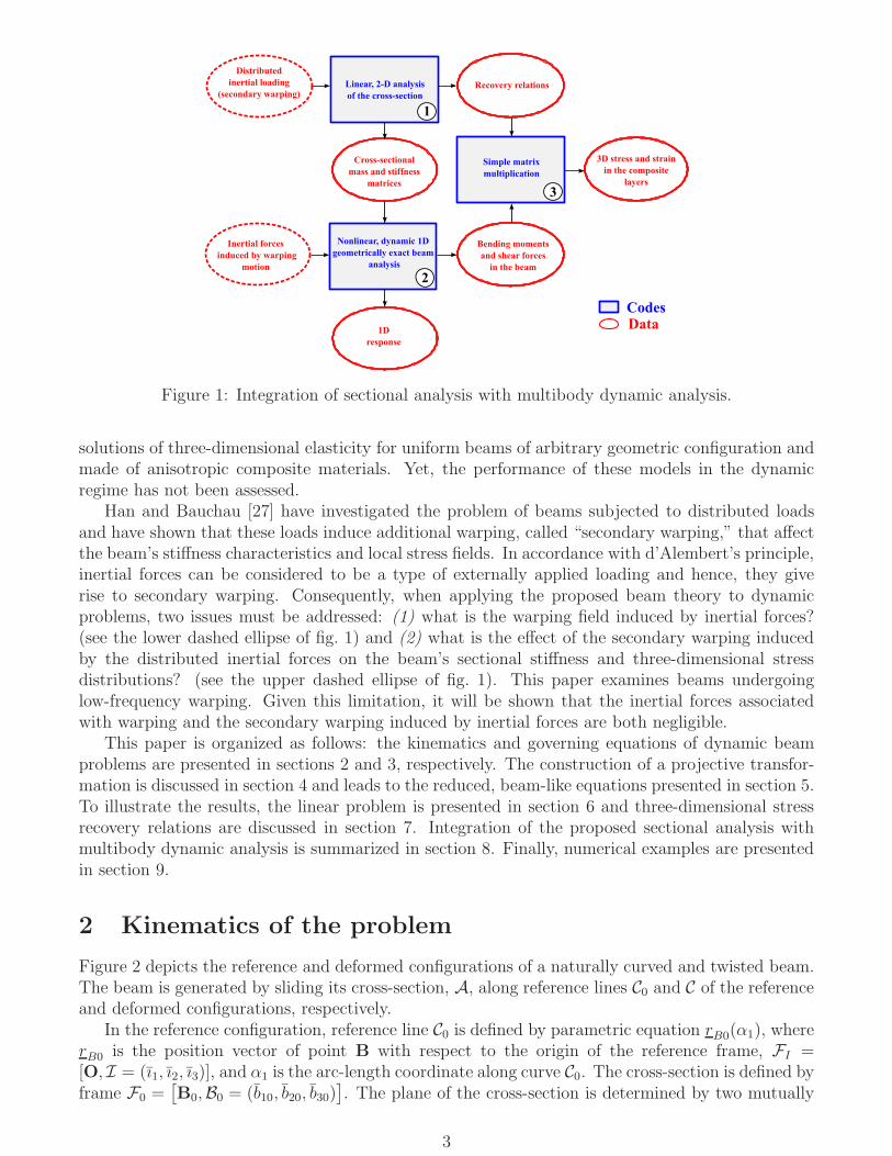
The overall process is depicted in fig. 1. The process starts with a linear, two-dimensionalanalysis of the cross-section (box 1 of fig. 1). This step, called “sectional analysis,” evaluatesthe sectional compliance and mass matrices. Given the distribution of material properties andgeometry of the cross-section, the sectional analysis provides the beam’s 6×6 sectional complianceand mass matrices. These sectional matrices take into account the three-dimensional deformationof the beam’s cross-section stemming from complex sectional geometries, material heterogeneity,and initial curvature of the reference line.
The second step of the process is a one-dimensional, nonlinear analysis of the geometricallyexact beam problem (box 2 of fig. 1). Typically, this analysis is performed via a finite elementdiscretization of the beam and time integration of the resulting discrete equations. At the endof this process, time histories of the stress resultants are available for the entire duration of thesimulation. The sectional compliance and mass matrices obtained from the sectional analysis areinputs to this process. The final step of the process is the recovery of local, three-dimensional strainand stress fields (box 3 of fig. 1). The recovery relationships are provided by the sectional analysis.
In summary, for small strain problems, the nonlinear, three-dimensional elasticity problem splitsinto two simpler problems: the linear sectional analysis problem and the nonlinear geometricallyexact beam problem. As illustrated in fig. 1, the sectional analysis is both a pre- and post-processorfor the beam analysis and is run once only, prior to the nonlinear beam analysis.
While the strategy has been applied to dynamic problems, little attention has been devoted toinertial effects. The goal of this paper is to assess the range of validity of the proposed beam theorywhen applied to dynamics problems. For static problems, the proposed approach provides exact
2
Linear, 2-D analysis
of the cross-section
Nonlinear, dynamic 1D
geometrically exact beam
analysis
Simple matrix
multiplication
Recovery relations
Cross-sectional
mass and stiffness
matrices
Bending moments
and shear forces
in the beam
3D stress and strain
in the composite
layers
CodesData
1D
response
2
1
3
Distributed
inertial loading
(secondary warping)
Inertial forces
induced by warping
motion
Figure 1: Integration of sectional analysis with multibody dynamic analysis.
solutions of three-dimensional elasticity for uniform beams of arbitrary geometric configuration andmade of anisotropic composite materials. Yet, the performance of these models in the dynamicregime has not been assessed.
Han and Bauchau [27] have investigated the problem of beams subjected to distributed loadsand have shown that these loads induce additional warping, called “secondary warping,” that affectthe beam’s stiffness characteristics and local stress fields. In accordance with d’Alembert’s principle,inertial forces can be considered to be a type of externally applied loading and hence, they giverise to secondary warping. Consequently, when applying the proposed beam theory to dynamicproblems, two issues must be addressed: (1) what is the warping field induced by inertial forces?(see the lower dashed ellipse of fig. 1) and (2) what is the effect of the secondary warping inducedby the distributed inertial forces on the beam’s sectional stiffness and three-dimensional stressdistributions? (see the upper dashed ellipse of fig. 1). This paper examines beams undergoinglow-frequency warping. Given this limitation, it will be shown that the inertial forces associatedwith warping and the secondary warping induced by inertial forces are both negligible.
This paper is organized as follows: the kinematics and governing equations of dynamic beamproblems are presented in sections 2 and 3, respectively. The construction of a projective transfor-mation is discussed in section 4 and leads to the reduced, beam-like equations presented in section 5.To illustrate the results, the linear problem is presented in section 6 and three-dimensional stressrecovery relations are discussed in section 7. Integration of the proposed sectional analysis withmultibody dynamic analysis is summarized in section 8. Finally, numerical examples are presentedin section 9.
2 Kinematics of the problem
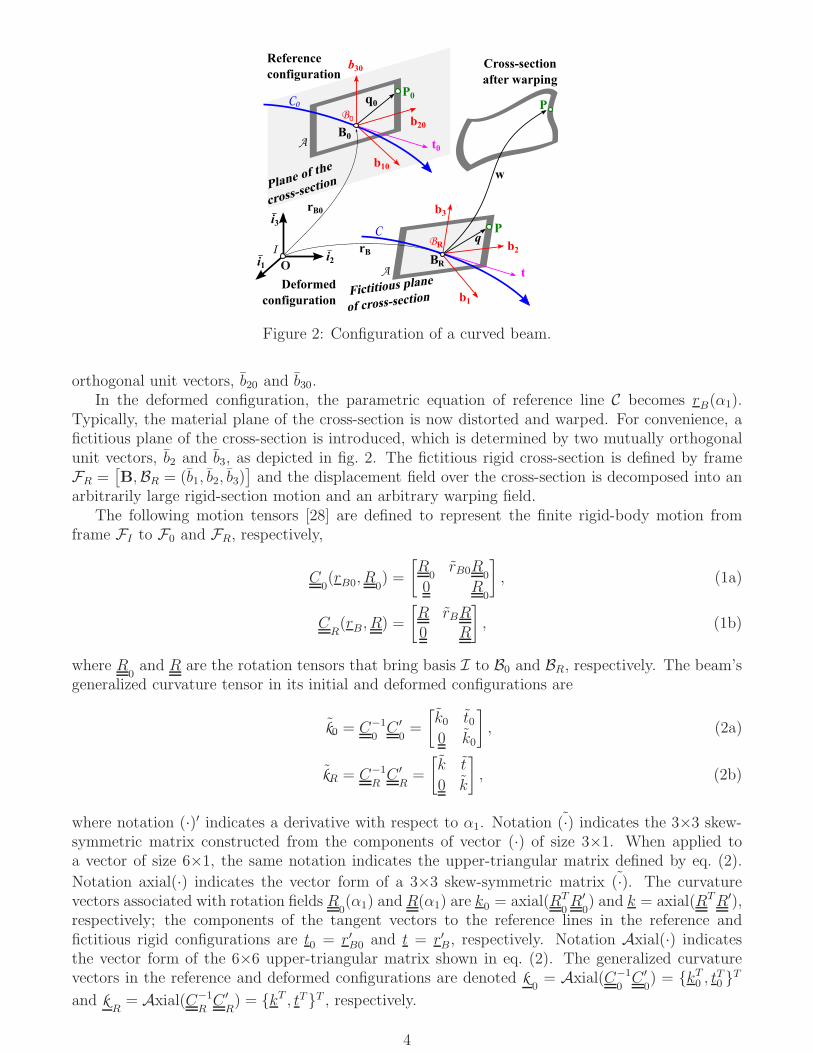
Figure 2 depicts the reference and deformed configurations of a naturally curved and twisted beam.The beam is generated by sliding its cross-section, A, along reference lines C0 and C of the referenceand deformed configurations, respectively.
In the reference configuration, reference line C0 is defined by parametric equation rB0(α1), where
rB0is the position vector of point B with respect to the origin of the reference frame, FI =
[O, I = (ı1, ı2, ı3)], and α1 is the arc-length coordinate along curve C0. The cross-section is defined byframe F0 =
[
B0,B0 = (b10, b20, b30)]
. The plane of the cross-section is determined by two mutually
3
P0
O
I
C0B
P
Deformed
configuration
Reference
configuration
B
Plane of the
cross-section
q0
Fictitious plane
of cross-section
P
Cross-section
after warping
B0
B
C
i1_
b3
b2
b1
b10
b20
b30
w
t0
t
rB
q
A
A
rB0
i3_
i2_
0
R
R
Figure 2: Configuration of a curved beam.
orthogonal unit vectors, b20 and b30.In the deformed configuration, the parametric equation of reference line C becomes rB(α1).
Typically, the material plane of the cross-section is now distorted and warped. For convenience, afictitious plane of the cross-section is introduced, which is determined by two mutually orthogonalunit vectors, b2 and b3, as depicted in fig. 2. The fictitious rigid cross-section is defined by frameFR =
[
B,BR = (b1, b2, b3)]
and the displacement field over the cross-section is decomposed into anarbitrarily large rigid-section motion and an arbitrary warping field.
The following motion tensors [28] are defined to represent the finite rigid-body motion fromframe FI to F0 and FR, respectively,
C0(rB0
, R0) =
[
R0rB0R
0
0 R0
]
, (1a)
CR(rB, R) =
[
R rBR0 R
]
, (1b)
where R0and R are the rotation tensors that bring basis I to B0 and BR, respectively. The beam’s
generalized curvature tensor in its initial and deformed configurations are
k0 = C−1
0C ′
0=
[
k0 t00 k0
]
, (2a)
kR = C−1
RC ′
R=
[
k t
0 k
]
, (2b)
where notation (·)′ indicates a derivative with respect to α1. Notation (·) indicates the 3×3 skew-symmetric matrix constructed from the components of vector (·) of size 3×1. When applied toa vector of size 6×1, the same notation indicates the upper-triangular matrix defined by eq. (2).
Notation axial(·) indicates the vector form of a 3×3 skew-symmetric matrix (·). The curvaturevectors associated with rotation fields R
0(α1) and R(α1) are k0 = axial(RT
0R′
0) and k = axial(RTR′),
respectively; the components of the tangent vectors to the reference lines in the reference andfictitious rigid configurations are t
0= r′B0
and t = r′B, respectively. Notation Axial(·) indicatesthe vector form of the 6×6 upper-triangular matrix shown in eq. (2). The generalized curvaturevectors in the reference and deformed configurations are denoted k
0= Axial(C−1
0C ′
0) = kT
0, tT
0T
and kR= Axial(C−1
RC ′
R) = kT , tTT , respectively.
4
For dynamic problems, motion tensor CRis a function of time, t. The components of the beam’s
generalized velocity vector, resolved in material basis, are
vR = C−1
RC
R=
[
ω v0 ω
]
, vR = Axial(C−1
RC
R) =
RT rBaxial(RT R)
=
vω
, (3)
where notation ˙(·) indicates a derivative with respect to time. Velocity vector vR combines velocityvector v of the cross-section’s reference point and its angular velocity, ω = axial(RT R), both resolvedin material basis B.
2.1 Acceleration components
Let α2 and α3 denote the in-plane material coordinates along the directions of unit vectors b20 andb30, respectively. The position vector of an arbitrary material point P of the beam in its referenceconfiguration becomes
r0(α1, α2, α3) = rB0
(α1) +R0(α1)q, (4)
where vector q = 0, α2, α3T . After deformation, the position vector of a material point becomes
r(α1, α2, α3, t) = rB(α1, t) +R (α1, t)[
q + w(α1, α2, α3, t)]
, (5)
where w is the warping field and its components resolved in basis B are denoted wi, i.e., w =w1b1 + w2b2 + w3b3.
The velocity vector of point P becomes
r = rB +R[
ω(q + w) + w]
= R[
v + w + ω(q + w)]
. (6)
Taking a second time derivative yields the components of the acceleration vector, resolved in thematerial basis, as
a = RT r = v − qω + ωv + ωωq
+ w + 2ωw + ( ˙ω + ωω)w.(7)
The first line of this equation lists the acceleration terms stemming from the rigid-section motionand the second line those originating from warping deformation; hence, the warping induced inertialforces are f I
W= ρ[w + 2ωw + ( ˙ω + ωω)w], where ρ is the material density.
Textbooks on vibration establish that the frequency of beam bending vibrations is Ω2
n ∝n4H/(mL4), where n is the mode number, L the beam’s length, H its bending stiffness, and mits mass per unit span. If a is a representative dimension of the cross-section, these quantitiescan be estimated as H ∝ Ea4 and m = ρa2. Furthermore, λn = L/n is a good estimate of thewave length of the associated vibration mode shape, leading to Ω2
n ∝ Ea2/(ρλ4n). If the beam isvibrating at this frequency, ‖f I
W‖ ≈ ρΩ2
n(1 + ‖ω‖/Ωn)2‖w‖ ≈ ρΩ2
n‖w‖, where the norm of theangular velocity vector was assumed to be of the same order of magnitude as the vibration fre-quency to obtain the last result. Finally, the norm of the inertial force vector can be estimated as‖f I
W‖ ≈ (a/λn)
4E‖w‖/a2. For beams undergoing torsional vibration, as similar reasoning yields
Ω2
n ∝ E/(ρλ2n), leading to ‖f I
W‖ ≈ (a/λn)
2E‖w‖/a2.The warping induced strains are estimated as ǫW ≈ ‖w‖/a, the corresponding stresses as σW =
EǫW , and stress gradients as ∇σW = σW/a. This leads to ‖f I
W‖ ≈ (a/λn)
4∇σW and ‖f I
W‖ ≈
(a/λn)2∇σW for beam undergoing bending and torsional vibrations, respectively. Clearly, for low-
frequency vibrations λn ≫ a and hence, ‖f I
W‖ ≪ ∇σW . Because the dynamic equilibrium condition
states that ∇σW + ‖f I
W‖+ rigid-section motion induced inertial forces = 0, the warping induced
inertial forces can be neglected.
5
In summary, for beams undergoing low-frequency vibration, defined as vibration for whichλn ≫ a, warping induced inertial forces can be neglected. The low-frequency assumption is notan additional assumption. Indeed, even for static problems, beam theory is valid only if stressesvary slowly along its span. Clearly, beam theory can only predict accurately low-frequency modesand for such modes, warping induced inertial forces are negligible. For high-frequency vibration,a three-dimensional elasticity model should be used and warping induced inertial forces should beincluded. Finally, it should be noted that in many practical applications, structures respond in theirlowest-frequency modes only; little vibratory energy is associated with the high-frequency modeswhich can be neglected altogether.
When warping induced inertial forces are negligible, the acceleration vector in eq. (7) reduces to
a ≈ v − qω + ωv + ωωq = z vR + ψΩR = π aR. (8)
Matrix z = [I,−q], matrix π = [z, ψ], and the following quantities were defined
ψ =
1 0 0 0 0 0 α3 α2
0 1 0 −α2 0 α3 0 00 0 1 0 −α3 α2 0 0
, aR =
vR
ΩR
. (9)
Let vi and ωi, i = 1, 2, 3, denote the ith components of velocity of the cross-section’s reference pointand its angular velocity, v and ω, respectively. Array ΩT
R = v3ω2−v2ω3, v1ω3−v3ω1, v2ω1−v1ω2, ω2
1+
ω2
3, ω2
1+ ω2
2, ω2ω3, ω1ω3, ω1ω2 and array aR collects all components related to the acceleration of
the rigid section.
2.2 Strain components
Because sectional warping generates strains that are of the same order as those due to rigid-sectionmotion, warping effects must to be taken into account when evaluating the strain field. Assumingsmall warping and strain components, the Green-Lagrange strain tensor reduces to
γ ≈ Aw′ +B w + z eR, (10)
where eR stores the beam’s sectional strains due to the fictitious rigid cross-section motion
eR = kR− k
0. (11)
These sectional strain measures are identical to those derived by Reissner [2] and Simo [3].Let ti0 and ki0 denote the ith components of the tangent and curvature vectors t
0and k
0,
respectively. In eq. (10), the following differential operators were defined
A =1√g
[
I0
]
, B =
[
DO
DI
]
, (12)
where scalar√g = t10 − k30α2 + k20α3 is the determinant of the metric tensor in the reference
configuration. In eq. (12), differential operators, DOand D
Iwere defined as
DO=
d −k30 k20
k30 +√g∂
∂α2
d −k10
−k20 +√g∂
∂α3
k10 d
, DI=
0√g∂
∂α2
0
0 0√g∂
∂α3
0√g∂
∂α3
√g∂
∂α2
, (13)
where scalar d = −(t20 − k10α3)∂(·)/∂α2 − (t30 + k10α3)∂(·)/∂α3. A more detailed derivation of thestrain components is given by Han and Bauchau [9].
6

2.3 Semi-discretization of the warping field
The following semi-discretization of the displacement field is performed,
w(α1, α2, α3) = N(α2, α3)w(α1), (14)
where matrix N(α2, α3) stores the two-dimensional shape functions used in the discretization and
array w(α1) the nodal values of the displacement field. Notation (·) indicates nodal quantities ofthe discretized variables. Let ℓ be the number of nodes used to discretize the beam’s cross-sectionand n = 3ℓ the total number of degrees of freedom. Introducing this discretization into eq. (6)and (10) yields the components of the acceleration vector and strain tensor as
a = N Π aR, (15a)
γ = AN w′ +BN w +N Z eR, (15b)
where matrices Z and Π stack the rows of matrices z and π, respectively, for each of the nodes overthe cross-section.
3 Governing equations
The beam’s governing equations will be derived based on the Hamiltonian formalism. The inertialforces is derived in section 3.1, followed by the investigation of strain energy of the system insection 3.2 and at last, governing equations are obtained.
3.1 Inertial forces
The beam is assumed to be made of linearly elastic, anisotropic materials. The cross-sectional dis-tribution of materials is arbitrary but remains uniform along the beam’s span. In view of eq. (15a),the nodal inertial force are
fI= −
∫
A
NTN Π aRρ√gdA = −MΠ aR = −m v + vTm v , (16)
where ρ is the mass density of the material and the mass matrix, of size n × n, is M =∫
AρNTN
√gdA. Because the inertial effects due to warping are ignored, the beam’s sectional
mass matrix, m, of size 6× 6, becomes
m = ZTMZ. (17)
Due to the nature of the problem, matrix m presents the following structure,
m =
m00 0 0 0 m00α3m −m00α2m
0 m00 0 −m00α3m 0 00 0 m00 m00α2m 0 00 −m00α3m m00α2m m11 0 0
m00α3m 0 0 0 m22 −m23
−m00α2m 0 0 0 −m23 m33
. (18)
The sectional mass per unit span is m00 =∫
Aρ√gdA; the coordinates of the sectional center of
mass with respect to the reference point are m00α2m =∫
Aρα2
√gdA and m00α3m =
∫
Aρα3
√gdA;
the sectional mass moments of inertia per unit span about to unit vectors b2 and b3 are m22 =∫
Aρα2
3
√gdA and m33 =
∫
Aρα2
2
√gdA, respectively; the sectional cross-product of inertia per unit
span ism23 =∫
Aρα2α3
√gdA; finally, the polar moment of inertia per unit span ism11 = m22+m33.
The following identity is used to yield the last equality in eq. (16),
−vTm v = ZTdiag (ω)MZ = ΨΩ. (19)
7
3.2 Strain energy
The strain energy density of the beam is
L =1
2
∫
A
γTDγ√gdA, (20)
where the components of the 6×6 material stiffness matrix resolved the material basis are denotedas D. Introducing the discretized components of strain tensor given by eq. (15b), the strain energydensity becomes
L =1
2
(
Z e + w′) [
M(
Z e + w′)
+ CT w]
+1
2wT
[
C(
Z e + w′)
+ E w]
. (21)
Matrices M , C, and E, each of size n× n, are
M =
∫
A
(AN)TD(AN)√gdA, (22a)
C =
∫
A
(AN)TD(BN)√gdA, (22b)
E =
∫
A
(BN)TD(BN)√gdA. (22c)
Given the distribution of material stiffness properties, these matrices can be evaluated by integrationover the cross-section.
3.3 Governing equations
For this problem, the strain energy density is also the Lagrangian of the system. The nodal forcesare introduced is introduced
p =∂L
∂(
w′ + Z eR
) =M(
w′ + Z eR
)
+ CT w. (23)
The nodal displacements and forces are dual variables in Hamilton’s formalism. The Hamiltonianof the system, denoted H , is defined via Legendre’s transformation [29] as H = pT (Z eR + w′)− L
and tedious algebra reveals that H = −1/2 xT (J H)x, where array x stores the nodal displacements
and forces xT = wT pT, and matrices H and J , both of size 2n× 2n, are defined as
H =
[
−M−1CT M−1
E − CM−1CT CM−1
]
, and J =
[
0 I−I 0
]
. (24)
Matrix H is Hamiltonian, i.e., (J H) = (J H)T .Hamilton’s principle, provides two sets of equations for the problem. The first set, w′ + Z eR =
∂H/∂p, is identical to eqs. (23), i.e., defines the nodal forces. The second set, p′ = −∂H/∂w +MΠ aR, provides the governing equations of the problem. The combination of the two sets defines2n first-order, ordinary differential equations with constant coefficients
x′ = J∂H
∂x= H x−
[
Z0
]
eR +
[
0MΠ
]
aR, (25)
where identity JT J = I was used. The corresponding homogenous problem, x′ = H x, provides thegoverning equations form the associated linear, static beam problem.
8
Equation (25) is the governing equations for geometrically nonlinear, dynamic three-dimensionalbeam problems. Although it can be solved directly, the computational cost is usually too high fora practical beam problems. A proper utilization of the beam’s span-wise uniformity leads to asignificant reduction of problem size. Clearly, the solution of eq. (25) is determined by the nature ofthe eigenvalues of Hamiltonian matrix H , as discussed by Zhong [26] and Han and Bauchau [9, 11].
For linear, static beam problems, i.e., x′ = H x, the twelve null and purely imaginary eigen-values of the Hamiltonian give rise to polynomial and trigonometric solutions [11], respectively,corresponding to the solution of Saint-Venant’s problem. Finally, the eigenvalues of the Hamilto-nian matrix presenting non-vanishing real parts give rise to exponentially decaying solutions, whichcan be usually ignored because their effect is significant near the beam’s ends only.
Equations (25) show that nonlinear dynamics beam problems are represented by a nonhomoge-neous Hamiltonian system. As expected from d’Alembert’s principle, inertial forces can be viewedas externally distributed loads: matrix MΠ and array aR store the loading pattern over the cross-section and the corresponding load distribution along the reference line, respectively. Consequently,dynamic beam problems form a special case of Almansi-Michell’s problem discussed by Han andBauchau [27]. Clearly, the solutions not only depend on the eigenvalues of matrix H but also onthe nonhomogeneous terms related to inertial forces. To reduce problem size, the three-dimensionalgoverning equations will be projected onto a subspace spanned by the twelve generalized eigenvec-tors of the Hamiltonian matrix associated with its null and purely imaginary eigenvalues and by aset of secondary warping modes related to the inertial forces.
4 Dimensional reduction
To solve Almansi-Michell’s problem, Han and Bauchau [27] expanded the applied load distributionfunction in Taylor series and the secondary warping modes associated with the various orders ofexpansion were taken into account accordingly. For simplicity, only the 0th order expansion of theinertial force is considered here. The augmented projection is constructed as follows
x = X g +QaR, (26)
where matrix X , matrix Q, and array g are defined as follows
X =
[
Z W0 Y
]
, Q =
[
UV
]
, g =
uf
. (27)
MatrixX , of size 2n×12, is symplectic because it stores the eigenvectors and generalized eigenvectorsof matrix H , see details in refs. [9, 27], implying the following identities
ZTY = I, and W TY = 0. (28)
Matrices W and Y , each of size n×6, are interpreted as the nodal warping and forces, respectively,associated with unit sectional stress resultants. Matrices U and V , each of size n × 11, are yet
undetermined and their ith columns store the secondary warping and nodal forces, respectively,induced by unit values of the ith entry of acceleration array aR. Finally, array g
T = uT fT storesthe six components of infinitesimal rigid-section motion, u, and stress resultants, f , both resolvedin the material basis.
Using projection (26), the Hamiltonian matrix reduces to
HX = X
[
−kR S
0 k TR
]
, (29a)
H
[
UV
]
=
[
WY
]
ZTMΠ−
[
0MΠ
]
. (29b)
9
Equation (29a) is the governing equation for the nodal warping and forces stored in matricesW andY , respectively, and is obtained by considering the homogeneous part of the problem only; eq. (29b)is the governing equation for the secondary warping, U , and is obtained from the non-homogeneouspart of the problem, assuming that matrices W and Y are known. Matrix S will be interpretedlater as the sectional compliance matrix.
As will be shown in sections 5 and 7, secondary warping affects the beam’s reduced govern-ing equations and the stress recovery process. Numerical examples will show that the effects ofsecondary warping are typically small for beam undergoing low-frequency vibration.
5 The one-dimensional beam equations
Introducing coordinate transformation (26) in governing equations (27), pre-multiplying by XT J ,and using the symplectic orthogonal property (28), leads to the reduced equations
uf
′
=
[
−kR S
0 k TR
]
uf
+
S GaR − eRm vR − vT
Rm vR
, (30)
where sectional mass matrix m is defined by eq. (17) and matrix G = −ZTV results from thesecondary warping. Identity (19) is used to derive eq. (30).
The last six equations of this set provide the equilibrium equations, f ′ + kRf = m vR − vTRm vR,
where the right-hand side are the distributed inertial forces due to rigid-section motion. The firstsix equations define the sectional constitutive laws, e = eW + eR = S(f +GaR), where the sectionalstrains due to warping are defined as
eW = u′ + kRu, (31)
and symmetric matrix S stores the components of the sectional compliance matrix resolved in thematerial basis.
To complete the formulation, sets of strain- and velocity-displacement relationships must bedeveloped. The motion of the cross-section combines the motion associated with the fictitiousrigid-section, see eq. (1b), with the additional infinitesimal rigid-section motion, u, included in thewarping field
C(α1) = CR
(
I + u)
. (32)
For the infinitesimal motion u, the corresponding motion tensor is found as exponential map, exp(u),and can be approximated as I + u. Motion tensor C describes the average motion of the deformedcross-section including warping.
The components of beam’s curvature vector in its deformed configuration are
k =[
CR
(
I + u)
]−1 [
CR
(
I + u)
]′
≈ kR + eW , (33)
where higher-order terms were neglected. Using eq. (31) then results in k − k0= eR + eW = e. The
components of beam’s beam’s generalized velocity are
v =[
CR
(
I + u)
]−1 ∂
∂t
[
CR
(
I + u)
]
≈ vR + u. (34)
Because u is infinitesimal, it is reasonable to assume that k ≈ kR, v ≈ vR and a = aR, where
array a stores the acceleration related terms for the average rigid-section motion. The nonlinearequations for three-dimensional dynamic beam problems, eqs. (25), have been reduced to a set of
10
24 equations,
v = Axial(
C−1C)
, (35a)
e = Axial(
C−1C ′)
−Axial(
C−1
0C ′
0
)
, (35b)
e = S(
f +GaR)
, (35c)
f′ − k Tf = mv − vTmv , (35d)
Kinematic equations (35a) and (35b) define the sectional velocity and strain measures for therigid-section motion. Equations (35c) and (35d) are constitutive and equilibrium equations, respec-tively, for nonlinear dynamic beam problems. The term GaR in eq. (35c) represents the effectsof secondary warping. Introducing constitutive equations (35c) into equilibrium equations (35d),leads to (S−1e)′ − k TS−1e = m v − vTm v − (GaR)
′ + k TGaR. Clearly, the relative magnitudes ofmatrices G and m reveals the relative importance of contributions from rigid-section inertial forcesand secondary warping induced inertial effects. In the numerical examples below, it will be shownthat matrix G is several orders magnitude smaller than matrix m and hence, can be ignored.
When the secondary warping due to acceleration, GaR, is neglected, governing equations (35)becomes identical to those derived by Reissner [2], and Simo and co-workers [3, 4]. The presentpaper has underlined the assumptions required to obtain these equations. Furthermore, because itis based on a two-dimensional model of the cross-section, the present approach provides an accurateexpression for the sectional compliance matrix and allows recovery of the three-dimensional stressstate at any point in the beam, see section 7.
6 The linear problem
The previous developments are valid for beams undergoing large motion but small strain. Forlinear problems, the beam undergoes small motion only, an important problem in its own right.The linear problem is obtained by setting C
R= I, which implies eR = 0 and vR = 0 . Moreover,
the acceleration given by eq. (7) reduces to a = w and the beam’s governing equation become
x′ = H x+
0
M ¨w
. (36)
The strain- and velocity-displacement relationships, eqs. (35a) and (35b), are now become v = uand e = u′ + k u, respectively. The acceleration components simply reduce to U and finally, thereduced governing equation of the problem, eq. (35), become
u′
= −k u+ S f, (37a)
f′
= mu+ k Tf, (37b)
The wave solutions of eqs. (36) are expressed in terms of exponential functions, x(α1, t) =x exp j(kα1 − ωt), where xT = wT pT stores the amplitude of the variables, j =
√−1 is the
imaginary unit, complex number k = kr + jki is the wavenumber, and ω is the circular frequency.Introducing this solution into eq. (36) gives the following eigenvalue problem
jk
wp
=
(
H −[
0 0ω2
M 0
])
wp
. (38)
The dispersion relationship, i.e., the relationship between ω and k, is obtained easily by solvingthis eigenvalue problem: for a given frequency ω, wave numbers k are the eigenvalue of eq. (38).
11
Because the system is Hamiltonian, the eigenvalues come in groups of four with the following formk = ±kr ± jki. Equivalently, eliminating p from eq. (38) yields a Hermitian eigenvalue problem
[
k2M + jk(C − CT ) + E − ω2M]
w = 0. (39)
The same procedure is applied to obtain the dispersion curves of reduced problem (37): intro-ducing the wave solutions u(α1, t) = u exp j(kα1−ωt) and f(α1, t) = f exp j(kα1−ωt) leads to thefollowing eigenvalue problem
jk
uf
=
[
−k S
−ω2m k T
]
uf
. (40)
Eliminating the sectional stress resultant then yields a Hermitian eigenvalue problem[
k2S−1 + jk(k TS−1 − S−1k ) + k
TS−1k − ω2m
]
u = 0. (41)
For a given frequency ω, 2n and 12 eigenvalues result from the original (eq. (39)) and reduced(eq. (41)) eigenproblems, respectively. Note that exp j(kα1 − ωt) = exp(−kiα1) exp j(krα1 − ωt)and hence, coefficient ki can be interpreted as the spatial decay rate of the corresponding mode:the modes with the smallest |ki| are the most important because they affect the largest portionof the beam. Accordingly, the dispersion relations provide a simply way of validating the dimen-sional reduction process: in the low-frequency range, the 12 dispersion curves of the reduced systemshould coincide with their 12 counterparts of the original system associated with lowest magnitudeof ki. Achenbach [30] has shown that the dispersion relationships predicted by planar Timoshenkobeam theory are in good agreement with those resulting from two-dimensional elasticity in thelow-frequency range. Volovoi and Hodges [31] compared the dispersion relationships for compositebeams based on the variational asymptotic method with those obtained from three-dimensionalelasticity; they reported good correlation in the low-frequency range. This validation will be per-formed numerically in section 9.1 for a set of more complex beam problems based on the proposedmodel.
7 Local stress recovery
Combining eqs. (26) and (27) yields the nodal displacement and force fields as
w = Z u+W f +WfaR, (42a)
p = Y f + YfaR, (42b)
where Wf= U −W ZT V and Y
f= V − Y ZT V . The first two terms on the right-hand side of
eq. (42a) describe the contributions of the rigid-section motion and stress resultants, respectively.The third term describes the effects of inertial forces and can be ignored for beams undergoinglow-frequency motion.
Introducing the nodal displacements and their derivatives into eq. (15b) yields the three-dimensional strain field as γ = AN(Z u′+W f ′)+BN(Z u+W f). This expression can be simplifiedwith the help of eqs. (35) and the fact that rigid-body motion creates no strains, AN Z+BN Z = 0,to find
γ =[
AN(
Z S +W k T)
+BN W]
f. (43)
Finally, the three-dimensional stress field is obtained from the constitutive laws as τ = Dγ. In-
troducing orthogonality condition (28) into eq. (42a), leads to u = Y T w, which implies that therigid-section motion is an average of the nodal displacements.
12

Another approach to validation of the dynamic model is to perform a modal analysis for thereduced one-dimensional model and compare the resulting mode shapes with those obtained fromthree-dimensional FEM analysis. Furthermore, the three-dimensional stress field recovered from theone-dimensional model can be compared with its counterpart obtained from the three-dimensionalmodel. Such validation will be presented for specific beam problems in section 9.2.
8 Overall analysis strategy
The overall analysis strategy is summarised in this section. In the first step, the sectional analysisuses standard finite element tools to evaluate the Hamiltonian of the system, eq. (24), based onthe stiffness matrices, M , C, and E defined by eqs. (22). The sectional analysis yields recoverymatrix W defined in eq. (26), which represents the nodal warping associated with unit sectionalstress resultants. The sectional compliance and mass matrices, S and m, are also provided bythe sectional analysis. The second step of the process is a one-dimensional, nonlinear analysis ofthe geometrically exact beam problem defined by eqs. (35). In the final step, eq. (43) is used torecover the three-dimensional stress field through a simple matrix multiplication. The inertial forcesinduced by warping are negligible compared to the inertial forces due to the rigid-section motion,as proved in section 2.1. The secondary warping effects, indicated by matrix U in eq. (26), GaR ineq. (35c), and W
fin eq. (42a) are also negligible. The numerical examples presented in section 9
all use this solution procedure.The proposed methodology presented here provides a unified analysis procedure for complex
beam model in flexible multibody dynamics. The assumptions made in the derivations above andtheir implications are summarized as follows. (1) The beam undergoes large motion but strainsand warping displacements remain small. (2) The beam undergoes low-frequency motion. Forsuch problems, both of the warping induced inertial forces and the secondary warping resultingfrom inertial forces can be ignored. (3) Beam properties remain uniform along its span althoughsectional material properties and geometric configuration are arbitrary. (4) The beam’s span ismuch larger than a representative dimension of the cross-section. Consequently, the developmentsfocus on the central solution, because the contributions of the extremity solutions are negligibleaway from the beam ends.
9 Numerical examples
To validate the proposed approach, a set of numerical examples will be presented. The proceduredescribed in the previous section was used for the solution of the examples.
9.1 Dispersion curves of two typical cross-sections
Figure 3 depicts two cross-sections: (a) a solid section and (b) a box section. The square solid sectionis of dimension b = 0.1 m and is made of steel with Young’s modulus E = 207 GPa, Poisson’s ratioν = 0.3, and mass density ρ1 = 7,800 kg·m−3. The square box section is of dimension b = 0.1 mand the wall consists of a single ply of graphite/epoxy material, of thickness tp = 0.018 m. Thematerial mass density is ρ2 = 1,600 kg·m−3 and the material stiffness properties are: longitudinalmodulus EL = 181 GPa, transverse modulus ET = 10.3 GPa, shearing modulus GLT = 7.17 GPa,and Poisson’s ratios νLT = 0.28 and νTN = 0.33. The lay-up angle is 30; 0 fibers are aligned withthe axis of the beam and a positive ply angle indicates a right-hand rotation about the local outernormal to the wall.
The proposed approach used meshes of 36 and 20 8-node two-dimensional elements for theanalyses of solid and box cross-sections, respectively. Dispersion curves of the following four beam
13

b B
30
tp
tp
b2
_
b3
_
Solid cross-section Box cross-section
b B b2
_
b3
_
Figure 3: Configuration of two cross-section.
configurations were investigated: (1) P1: a straight beam with the isotropic solid section, (2) P2:a pre-twisted beam (kT = π, 0, 0 m−1) with the isotropic solid section, (3) P3: a straight beamwith the heterogenous box section, and (4) P4: a pre-twisted beam (kT = π, 0, 0 m−1) with theheterogenous box section.
5
4
3
2
1
0
-1
-2
ω/Ω
Re(bk
)Im
(bk
)
0 0.2 0.4 0.6 0.8 1.0 1.2 1.4 1.6 1.8 2.0
Figure 4: Dispersion curves for beam P1.1D model: dashed line, 3D model: solidline. Extension-torsion: (⊳) and (⊲), bending-shearing: (), () and (×).
5
4
3
2
1
0
-1
-20 0.2 0.4 0.6 0.8 1.0 1.2 1.4 1.6 1.8 2.0
/
Re(bk
)
I b
k)
Figure 5: Dispersion curves for beam P2.1D model: dashed line, 3D model: solidline. Extension-torsion: (⊳) and (⊲), bending-shearing: (), () and (×).
To generate the dispersion curves, the following procedure was used. Wave numbers are evalu-ated at discrete frequencies, ωk = k∆Ω, k = 0, 1, 2, . . . , N. The Arnoldi algorithm is used to extractthe eigenvalues of the system. For the reduced beam equations, all 12 eigenvalues are extracted;for the three-dimensional model, the 60 eigenvalues with the lowest absolute values are obtained.To draw the dispersion curves, the eigenvalues of the three-dimensional model must be trackedproperly. For k = 0, the 20 eigenvalues with the lowest norm are retained. For the next frequency,k = 1, 20 eigenvalues are selected from the pool of the 60 eigenvalues with the lowest norm. Theselection procedure identifies 20 eigenvalues that are in the close neighborhood of those select at k= 0. The distances between the 20 eigenvalues at step k = 0 and all the eigenvalues obtained at k= 1 are evaluated; the distance is defined as the norm of the difference between the complex wavenumbers. The sum of the distances of the 20 eigenvalues selected at k = 1 is the smallest for allchoices of 20 eigenvalues within the pool of 60. A multi-object tracking algorithm is used for thistask. The process then repeats for the successive values of k.
The dispersion curves for these four problems are shown in fig. 4 to 7. The dispersion curvesfor the one- and three-dimensional beam models were obtained, as presented in section 6. Wavenumbers were normalized by the sectional dimension as bk and frequencies were normalized as ω/Ω,where Ω =
√
E/(ρ1b2) and Ω =√
EL/(ρ2b2) for the solid and box sections, respectively. Becausethe eigenvalues appear in groups of four with the following form k = ±kr ± jki, the figures showthe positive real and negative imaginary parts of the wave number only.
For each mode, the six stress resultants can be evaluated by integrating the out-of-plane stresscomponents over the cross-section. Based on this information, the modes fall into two groups: thefirst group of modes, called the “extension-torsion” modes, present stress resultants involving ex-
14
tension forces and twisting moments only, the second group of modes, called the “bending-shearing”modes, present stress resultants involving bending moments and shear forces only. For static prob-lems, the twelve modes with vanishing real parts form four Jordan chains [11]. Two chains, each ofsize two, are associated with deformation modes of the structure when subjected to unit extensionforce and torque, respectively. The other two chains, each of size four, capture the deformationmodes of the structure subjected unit bending moments and shear forces in the two transversedirections.
Low-frequency dynamics problems can be viewed as small perturbations of static problems butfor dynamics problems, Luongo [32] pointed out that the Jordan chains break down. The twoJordan chains of length two degenerate into two pairs of real eigenvalues of opposite signs, andthe corresponding modes exhibits both extension and torsion for problems P2, P3, and P4. Forproblem P1, extension and torsion modes are decoupled. The two chains of length four degenerateinto pairs of complex conjugate eigenvalues and two pairs of real eigenvalues of opposite signs, andthe corresponding modes exhibits both shearing and bending. The multiplicities of each eigenvaluesare listed in table 1.
2
1
0
-10 0.05 0.1 0.15 0.2
/
Re(bk
b
k
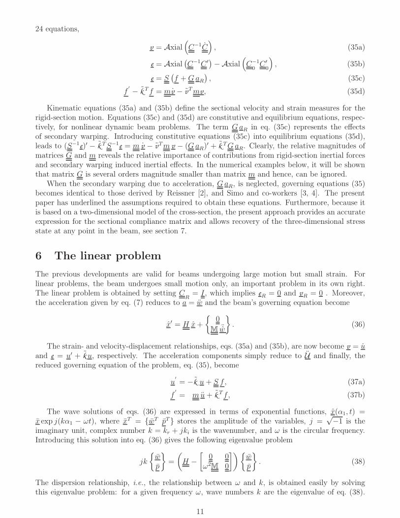
Figure 6: Dispersion curves for beam P3.1D model: dashed line, 3D model: solidline. Extension-torsion: (⊳) and (⊲), bending-shearing: (), () and (×), extremity modes:(⋄).
2
1
0
-10 0.05 0.1 0.15 0.2
/
Re(bk
b
k
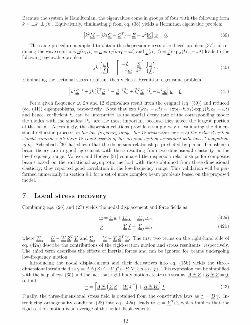
Figure 7: Dispersion curves for beam P4.1D model: dashed line, 3D model: solidline. Extension-torsion: (⊳) and (⊲), bending-shearing: (), () and (×), extremity modes:(⋄).
Table 1: Multiplicity of the eigenvalues k and their low-frequency limit, bkr0 = limω→0 bkr(ω).Nature of the deformation: extension (E), torsion (T), bending (B), shearing (S).
(E) (T) (E-T) (B-S) (B-S)ki = 0 ki = 0 ki = 0 ki = 0 ki 6= 0
Mult. bkr0 Mult. bkr0 Mult. kr0 Mult. bkr0 Mult. bkr0P1 2× 0 2× 0 0× 4× 0 4× 0P2 0× 0× 4× 0 4× b‖k‖ 4× b‖k‖P3 0× 0× 4× 0 4× 0 4× 0P4 0× 0× 4× 0 4× b‖k‖ 4× b‖k‖
For isotropic beams, problems P1 andP2, the dispersion curves of the one- and three-dimensionalmodels are in close agreement with each other for ω/Ω ∈ [0, 2], or ω ∈ [0, 103] kHz. For compositebeams, problems P3 and P4, good agreement is observed for ω/Ω ∈ [0, 0.06], or ω ∈ [0, 6.38] kHz.As frequency increase, one pairs of extremity modes, i.e., modes with vanishing resultants, becomesdominant because the associated Im(k) is very small. Clearly, both geometric configuration andmaterial properties affect the range of validity of the one-dimensional beam model. As observedin these examples, the range of validity of the proposed dynamic analysis procedure is far smaller
15

for beams made of anisotropic materials than for those made of isotropic materials. Clearly, theterm “low-frequency vibration” must be quantified if it is to be used as a criterion for assessing theaccuracy of beam models.
9.2 Modal analysis of a composite beam
i1
_
i2
_
i3
_
1D and 3D beam model
b3
_
b2
_
B
Figure 8: Configuration of the composite box.
To further assess the validity of the proposed beam model in the dynamic regime, a cantileveredcomposite beam of length L = 2.0 m with the untwisted box section described in section 9.1 wasinvestigated. The proposed approach used 20, 8-node two-dimensional elements for the sectionalanalysis and 8, 4-node one-dimensional elements for the beam analysis. A reference solution wasobtained with ABAQUS using 20-node three-dimensional brick elements: 20 elements were usedover the cross-section and 80 along the beam’s span. Sectional analysis provides the beam’s massproperties as m00 = 9.446 kg/m and m22 = 0.01096 kg·m. The predicted sectional stiffness matrixis
S∗−1
105=
3, 840 0 0 −66.71 0 00 626.6 0 0 37.11 00 0 626.6 0 0 37.11
−66.71 0 0 2.246 0 00 37.11 0 0 4.573 00 0 37.11 0 0 4.573
, (44)
where units of the entries are as follows: N·m−1 for i, j = 1, 2, 3; N·m for i, j = 4, 5, 6; and N forthe other entries. Material anisotropy causes extension-twisting and shearing-bending coupling toarise, resulting in the off-diagonal terms of the sectional stiffness matrix.
As discussed in section 5, distributed inertial forces generate secondary warping characterizedby matrix G appearing in eq. (30) and such effects are usually negligible. These arguments can bevalidated by evaluating matrix G and noticing that the magnitude of this matrix is 3 to 4 orderssmaller than the mass matrix m for this example.
Modal analysis was performed for both the proposed and ABAQUS models. Table 2 lists thefirst seven bending modes predicted by the two models; good correlation is observed between thetwo sets of predictions. Each natural frequency in bending listed in the table has two associatedbending modes with eigenvectors in two orthogonal planes. In most cases, the natural frequenciespredicted by the beam model were slightly lower than those predicted by the ABAQUS model.This stems from a difference in the boundary conditions: for the ABAQUS model, all displacementcomponents at all nodes of the root section are constrained whereas for the proposed model, averagesectional displacement are constrained, but warping is allowed. Consequently, the beam model ismore compliant than its three-dimensional counterpart, resulting in lower frequencies.
16
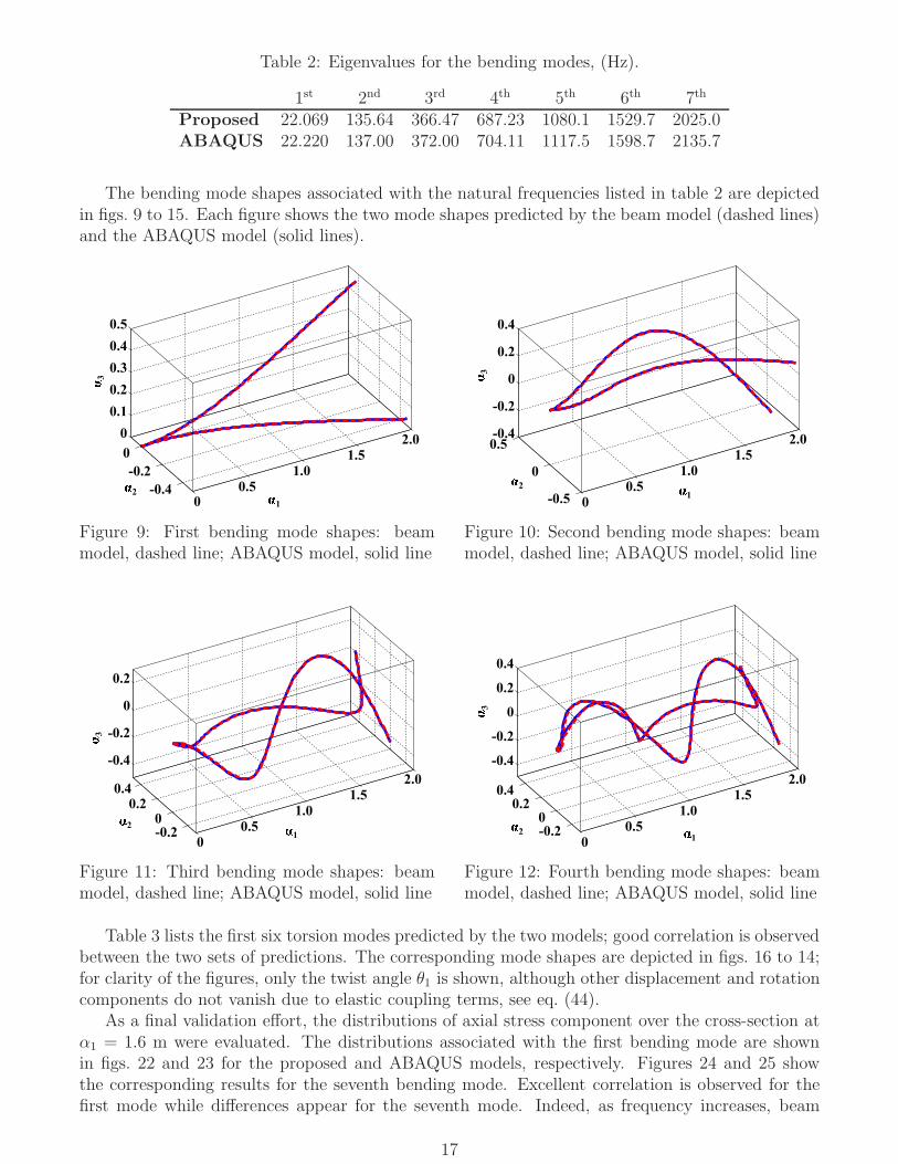
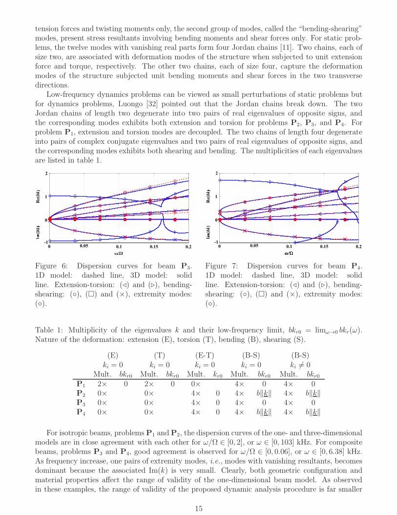
Table 2: Eigenvalues for the bending modes, (Hz).
1st 2nd 3rd 4th 5th 6th 7th
Proposed 22.069 135.64 366.47 687.23 1080.1 1529.7 2025.0ABAQUS 22.220 137.00 372.00 704.11 1117.5 1598.7 2135.7
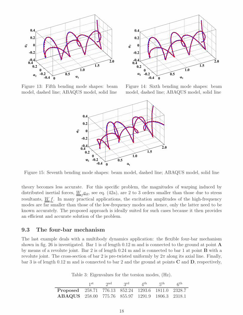
The bending mode shapes associated with the natural frequencies listed in table 2 are depictedin figs. 9 to 15. Each figure shows the two mode shapes predicted by the beam model (dashed lines)and the ABAQUS model (solid lines).
1
2
3
00.5
1.0
1.5
2.0
-0.4
-0.2
0
0
0.1
0.2
0.3
0.4
0.5
Figure 9: First bending mode shapes: beammodel, dashed line; ABAQUS model, solid line
1
2
0
0.5
1.0
1.5
2.0
-0.5
0
0.5-0.4
-0.2
0
0.2
0.4
3
Figure 10: Second bending mode shapes: beammodel, dashed line; ABAQUS model, solid line
1
2
3
0
0.5
1.0
1.5
2.0
-0.20
0.20.4
-0.4
-0.2
0
0.2
Figure 11: Third bending mode shapes: beammodel, dashed line; ABAQUS model, solid line
12
0
0.5
1.0
1.5
2.0
-0.20
0.20.4
-0.4
-0.2
0
0.2
0.4
3
Figure 12: Fourth bending mode shapes: beammodel, dashed line; ABAQUS model, solid line
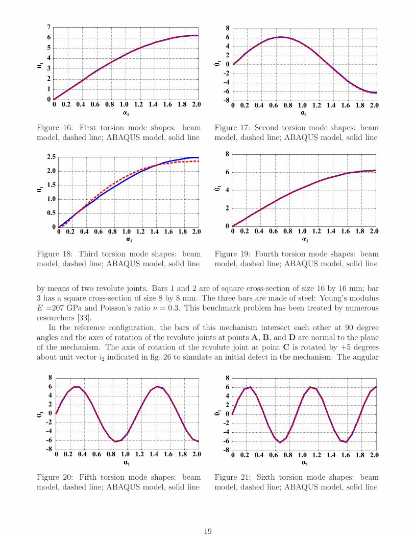
Table 3 lists the first six torsion modes predicted by the two models; good correlation is observedbetween the two sets of predictions. The corresponding mode shapes are depicted in figs. 16 to 14;for clarity of the figures, only the twist angle θ1 is shown, although other displacement and rotationcomponents do not vanish due to elastic coupling terms, see eq. (44).
As a final validation effort, the distributions of axial stress component over the cross-section atα1 = 1.6 m were evaluated. The distributions associated with the first bending mode are shownin figs. 22 and 23 for the proposed and ABAQUS models, respectively. Figures 24 and 25 showthe corresponding results for the seventh bending mode. Excellent correlation is observed for thefirst mode while differences appear for the seventh mode. Indeed, as frequency increases, beam
17
12
3
0
0.5
1.0
1.5
2.0
-0.4-0.20
0.20.4-0.4
-0.2
0
0.2
0.4
Figure 13: Fifth bending mode shapes: beammodel, dashed line; ABAQUS model, solid line
1
2
3
0
0.5
1.0
1.5
2.0
-0.4-0.20
0.20.4-0.4
-0.2
0
0.2
0.4
Figure 14: Sixth bending mode shapes: beammodel, dashed line; ABAQUS model, solid line
1
2
3
0
0.5
1.0
1.5
2.0
-0.4-0.20
0.20.4-0.4
-0.2
0
0.2
0.4
Figure 15: Seventh bending mode shapes: beam model, dashed line; ABAQUS model, solid line
theory becomes less accurate. For this specific problem, the magnitudes of warping induced bydistributed inertial forces, W
faR, see eq. (42a), are 2 to 3 orders smaller than those due to stress
resultants, W f . In many practical applications, the excitation amplitudes of the high-frequencymodes are far smaller than those of the low-frequency modes and hence, only the latter need to beknown accurately. The proposed approach is ideally suited for such cases because it then providesan efficient and accurate solution of the problem.
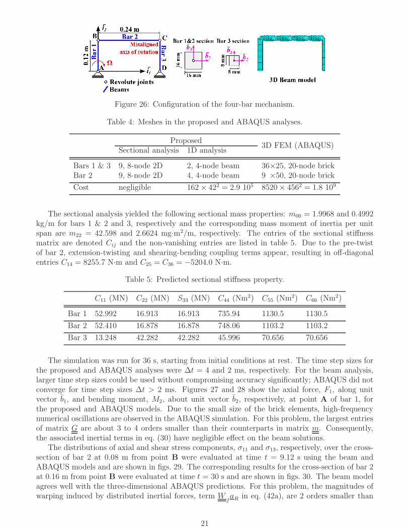
9.3 The four-bar mechanism
The last example deals with a multibody dynamics application: the flexible four-bar mechanismshown in fig. 26 is investigated. Bar 1 is of length 0.12 m and is connected to the ground at point Aby means of a revolute joint. Bar 2 is of length 0.24 m and is connected to bar 1 at point B with arevolute joint. The cross-section of bar 2 is pre-twisted uniformly by 2π along its axial line. Finally,bar 3 is of length 0.12 m and is connected to bar 2 and the ground at points C and D, respectively,
Table 3: Eigenvalues for the torsion modes, (Hz).
1st 2nd 3rd 4th 5th 6th
Proposed 258.71 776.13 852.24 1293.6 1811.0 2328.7ABAQUS 258.00 775.76 855.97 1291.9 1806.3 2318.1
18
1
1
0 0.2 0.4 0.6 0.8 1.0 1.2 1.4 1.6 1.8 2.00
1
2
3
4
5
6
7
Figure 16: First torsion mode shapes: beammodel, dashed line; ABAQUS model, solid line
1
!
1
0 0.2 0.4 0.6 0.8 1.0 1.2 1.4 1.6 1.8 2.0-8
-6
-4
-2
0
2
4
6
8
Figure 17: Second torsion mode shapes: beammodel, dashed line; ABAQUS model, solid line
"1
#
1
0 0.2 0.4 0.6 0.8 1.0 1.2 1.4 1.6 1.8 2.00
0.5
1.0
1.5
2.0
2.5
Figure 18: Third torsion mode shapes: beammodel, dashed line; ABAQUS model, solid line
$1
%
1
0 0.2 0.4 0.6 0.8 1.0 1.2 1.4 1.6 1.8 2.00
2
4
6
8
Figure 19: Fourth torsion mode shapes: beammodel, dashed line; ABAQUS model, solid line
by means of two revolute joints. Bars 1 and 2 are of square cross-section of size 16 by 16 mm; bar3 has a square cross-section of size 8 by 8 mm. The three bars are made of steel: Young’s modulusE =207 GPa and Poisson’s ratio ν = 0.3. This benchmark problem has been treated by numerousresearchers [33].
In the reference configuration, the bars of this mechanism intersect each other at 90 degreeangles and the axes of rotation of the revolute joints at points A, B, and D are normal to the planeof the mechanism. The axis of rotation of the revolute joint at point C is rotated by +5 degreesabout unit vector ı2 indicated in fig. 26 to simulate an initial defect in the mechanism. The angular
&1
'
1
0 0.2 0.4 0.6 0.8 1.0 1.2 1.4 1.6 1.8 2.0-8
-6
-4
-2
0
2
4
6
8
Figure 20: Fifth torsion mode shapes: beammodel, dashed line; ABAQUS model, solid line
(1
*
1
0 0.2 0.4 0.6 0.8 1.0 1.2 1.4 1.6 1.8 2.0-8
-6
-4
-2
0
2
4
6
8
Figure 21: Sixth torsion mode shapes: beammodel, dashed line; ABAQUS model, solid line
19

−0.05 0 0.05−0.05
0
0.05
α2
α 3
−1000
−500
0
500
1000
Figure 22: Axial stress component, σ11, distri-bution for the 1st bending mode at α1 = 1.6 m,beam model.
−0.05 0 0.05−0.05
0
0.05
α2
α 3
−1000
−500
0
500
1000
Figure 23: Axial stress component, σ11, distri-bution for the 1st bending mode at α1 = 1.6 m,ABAQUS model.
−0.05 0 0.05−0.05
0
0.05
α2
α 3
−4
−3
−2
−1
0
1
2
3
4x 10
5
Figure 24: Axial stress component, σ11, distri-bution for the 7th bending mode at α1 = 1.6 m,beam model.
−0.05 0 0.05−0.05
0
0.05
α2
α 3
−4
−3
−2
−1
0
1
2
3
4x 10
5
Figure 25: Axial stress component, σ11, distri-bution for the 7th bending mode at α1 = 1.6 m,ABAQUS model.
velocity at point A of bar 1 is prescribed as
Ω(t) =
0.3[1− cos (πt)] rad/s, 0 ≤ t ≤ 1 s;
0.6 rad/s, t ≥ 1 s.(45)
For reference, a full three-dimensional FEM analysis was performed using ABAQUS. The twoend-sections of each bar were enforced to remain rigid using multi-point constraints in ABAQUS.The four revolute joints are modeled using connector elements in ABAQUS. The meshes used inthe proposed approach and ABAQUS are summarized in table 4. The computational costs forboth the proposed and ABAQUS analyses are also shown table 4. In both cases, the main costper iteration is the factorization of the stiffness matrix, which can be estimated [34] as C ∝ nm2,where n is the size of the stiffness matrix and m its average half-bandwidth. The cost for sectionalanalysis is negligible because it is performed once only at the onset of the simulation, as discussedin section 8. For this example, the proposed approach is four orders of magnitude more efficientthan three-dimensional FEM analysis.
20
0+,- .
Bar 2
Bar
1 Bar 3
A
B C
D12346
Revolute jointsBeams
Misaligned
axis of rotation
Ω
Figure 26: Configuration of the four-bar mechanism.
Table 4: Meshes in the proposed and ABAQUS analyses.
Proposed3D FEM (ABAQUS)
Sectional analysis 1D analysis
Bars 1 & 3 9, 8-node 2D 2, 4-node beam 36×25, 20-node brickBar 2 9, 8-node 2D 4, 4-node beam 9 ×50, 20-node brick
Cost negligible 162× 422 = 2.9 105 8520× 4562 = 1.8 109
The sectional analysis yielded the following sectional mass properties: m00 = 1.9968 and 0.4992kg/m for bars 1 & 2 and 3, respectively and the corresponding mass moment of inertia per unitspan are m22 = 42.598 and 2.6624 mg·m2/m, respectively. The entries of the sectional stiffnessmatrix are denoted Cij and the non-vanishing entries are listed in table 5. Due to the pre-twistof bar 2, extension-twisting and shearing-bending coupling terms appear, resulting in off-diagonalentries C14 = 8255.7 N·m and C25 = C36 = −5204.0 N·m.
Table 5: Predicted sectional stiffness property.
C11 (MN) C22 (MN) S33 (MN) C44 (Nm2) C55 (Nm2) C66 (Nm2)
Bar 1 52.992 16.913 16.913 735.94 1130.5 1130.5
Bar 2 52.410 16.878 16.878 748.06 1103.2 1103.2
Bar 3 13.248 42.282 42.282 45.996 70.656 70.656
The simulation was run for 36 s, starting from initial conditions at rest. The time step sizes forthe proposed and ABAQUS analyses were ∆t = 4 and 2 ms, respectively. For the beam analysis,larger time step sizes could be used without compromising accuracy significantly; ABAQUS did notconverge for time step sizes ∆t > 2 ms. Figures 27 and 28 show the axial force, F1, along unitvector b1, and bending moment, M2, about unit vector b2, respectively, at point A of bar 1, forthe proposed and ABAQUS models. Due to the small size of the brick elements, high-frequencynumerical oscillations are observed in the ABAQUS simulation. For this problem, the largest entriesof matrix G are about 3 to 4 orders smaller than their counterparts in matrix m. Consequently,the associated inertial terms in eq. (30) have negligible effect on the beam solutions.
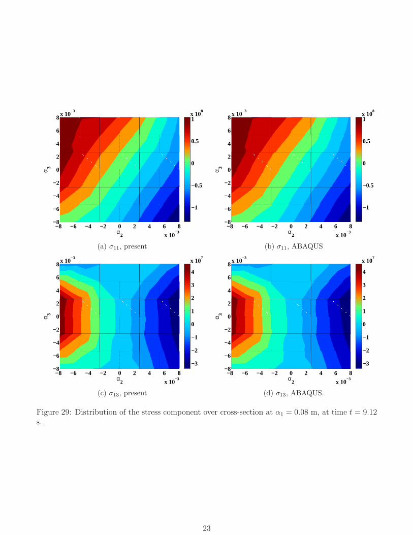
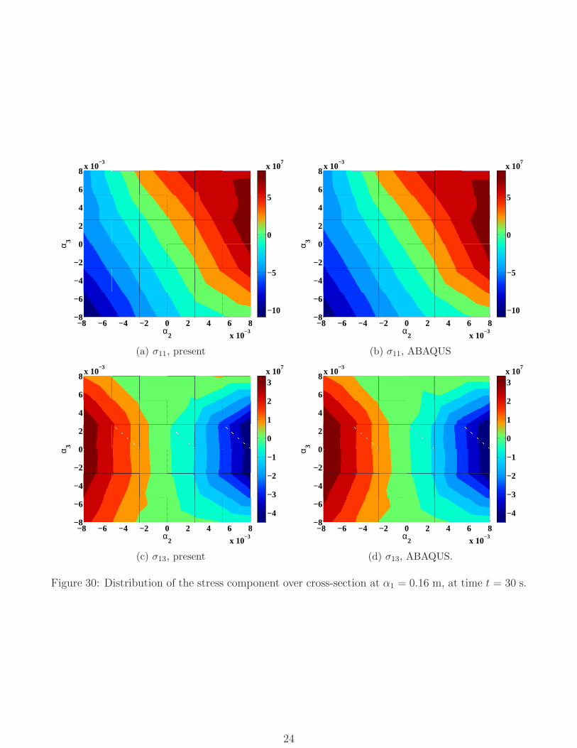
The distributions of axial and shear stress components, σ11 and σ13, respectively, over the cross-section of bar 2 at 0.08 m from point B were evaluated at time t = 9.12 s using the beam andABAQUS models and are shown in figs. 29. The corresponding results for the cross-section of bar 2at 0.16 m from point B were evaluated at time t = 30 s and are shown in figs. 30. The beam modelagrees well with the three-dimensional ABAQUS predictions. For this problem, the magnitudes ofwarping induced by distributed inertial forces, term W
faR in eq. (42a), are 2 orders smaller than
21

T789 :;<
F
1
=>?@
0 6 EG EH GJ KL KMNMLLL
NJLLL
NGLLL
0
GLLL
JLLL
6000
Figure 27: Reaction force, F1, at joint A. Proposed: dashed line, ABAQUS: thinner solid line
OPQR SUV
M
WXYZ[\
0 6 ]^ ]_ ^` ab acd^bb
d]bb
0
100
Figure 28: Reaction force, M2, at joint A. Proposed: dashed line, ABAQUS: thinner solid line
those of warping due to stress resultants, W f . Consequently, secondary warping has little effecton the three-dimensional stress distributions.
10 Conclusions
Most beam theories have been developed for application to dynamic problems, yet surprisingly littleattention has been devoted to inertial effects. Warping deformation is known to affect sectionalstiffness and stress distributions significantly, and hence, is included in the evaluation of the strainenergy. On the other hand, cross-sections are assumed to remain rigid when evaluating the kineticenergy.
This paper has assessed the validity of beam theory proposed by the authors when applied todynamic problems by answering two questions: (1) what is the warping field induced by inertialforces? and (2) what is the effect of the secondary warping induced by the distributed inertial forcesof the beam’s sectional stiffness and three-dimensional stress distributions?
Dispersion curves provide a powerful tool for describing the dynamic behavior of structures.To validate the proposed model, dispersion curves were computed for straight and pre-twistedbeams made of isotropic or anisotropic materials. In all cases, the dispersion curves computed bythe proposed beam models were found to be in good agreement with those obtained from three-dimensional models in the low-frequency range. These examples show that the term “low-frequencywarping” must be defined precisely: the beam’s geometric configuration and the nature of thematerials it is made of alter the range of validity of the model.
The inertial forces induced by warping deformation were proved to be negligible compared toelastic forces. Numerical examples were used to assess the importance of secondary warping. Forlow-frequency warping, the effects of secondary warping were found to be negligible. To furtherassess the accuracy of the proposed model, the twenty lowest modes of a cantilevered beam-likestructure were computed using both beam and three-dimensional models. The frequencies, modeshapes, and associated stress distributions predicted by the two models were found to be in good
22
−8 −6 −4 −2 0 2 4 6 8
x 10−3
−8
−6
−4
−2
0
2
4
6
8x 10
−3
α2
α 3
−1
−0.5
0
0.5
1x 10
8
(a) σ11, present
−8 −6 −4 −2 0 2 4 6 8
x 10−3
−8
−6
−4
−2
0
2
4
6
8x 10
−3
α2
α 3
−1
−0.5
0
0.5
1x 10
8
(b) σ11, ABAQUS
−8 −6 −4 −2 0 2 4 6 8
x 10−3
−8
−6
−4
−2
0
2
4
6
8x 10
−3
α2
α 3
−3
−2
−1
0
1
2
3
4
x 107
(c) σ13, present
−8 −6 −4 −2 0 2 4 6 8
x 10−3
−8
−6
−4
−2
0
2
4
6
8x 10
−3
α2
α 3
−3
−2
−1
0
1
2
3
4
x 107
(d) σ13, ABAQUS.
Figure 29: Distribution of the stress component over cross-section at α1 = 0.08 m, at time t = 9.12s.
23
−8 −6 −4 −2 0 2 4 6 8
x 10−3
−8
−6
−4
−2
0
2
4
6
8x 10
−3
α2
α 3
−10
−5
0
5
x 107
(a) σ11, present
−8 −6 −4 −2 0 2 4 6 8
x 10−3
−8
−6
−4
−2
0
2
4
6
8x 10
−3
α2
α 3
−10
−5
0
5
x 107
(b) σ11, ABAQUS
−8 −6 −4 −2 0 2 4 6 8
x 10−3
−8
−6
−4
−2
0
2
4
6
8x 10
−3
α2
α 3
−4
−3
−2
−1
0
1
2
3x 10
7
(c) σ13, present
−8 −6 −4 −2 0 2 4 6 8
x 10−3
−8
−6
−4
−2
0
2
4
6
8x 10
−3
α2
α 3
−4
−3
−2
−1
0
1
2
3x 10
7
(d) σ13, ABAQUS.
Figure 30: Distribution of the stress component over cross-section at α1 = 0.16 m, at time t = 30 s.
24
agreement.With the proposed approach, the nonlinear, dynamic three-dimensional equations of beams are
decomposed into a linear, sectional analysis, and a nonlinear, one-dimensional analysis along thebeam’s span. The proposed approach can be integrated into existing nonlinear beam models easily.It provides the beam’s sectional stiffness matrix that includes the effect of warping deformation.Furthermore, it enable the accurate evaluation of three-dimensional stress fields. The completeprocess is three to four orders of magnitude more computationally efficient than three-dimensionalfinite element analysis.
References
[1] O.A. Bauchau and J.I. Craig. Structural Analysis with Application to Aerospace Structures.Springer, Dordrecht, Heidelberg, London, New-York, 2009.
[2] E. Reissner. On one-dimensional large-displacement finite-strain beam theory. Studies inApplied Mathematics, 52:87–95, 1973.
[3] J.C. Simo. A finite strain beam formulation. The three-dimensional dynamic problem. Part I.Computer Methods in Applied Mechanics and Engineering, 49(1):55–70, 1985.
[4] J.C. Simo and L. Vu-Quoc. A three-dimensional finite strain rod model. Part II: Computationalaspects. Computer Methods in Applied Mechanics and Engineering, 58(1):79–116, 1986.
[5] M. Borri, G.L. Ghiringhelli, and T. Merlini. Linear analysis of naturally curved and twistedanisotropic beams. Composites Engineering, 2(5-7):433–456, 1992.
[6] D.H. Hodges. Nonlinear Composite Beam Theory. AIAA, Reston, Virginia, 2006.
[7] E. Carrera, G. Gaetano, and M. Petrolo. Beam Structures: Classical and Advanced Theories.John Wiley & Sons, New York, 2011.
[8] O.A. Bauchau and S.L. Han. Three-dimensional beam theory for flexible multibody dynamics.Journal of Computational and Nonlinear Dynamics, 9(4):041011 (12 pages), 2014.
[9] S.L. Han and O.A. Bauchau. Nonlinear three-dimensional beam theory for flexible multibodydynamics. Multibody System Dynamics, 34(3):211–242, July 2015.
[10] S.L. Han and O.A. Bauchau. Manipulation of motion via dual entities. Nonlinear Dynamics,85(1):509–524, July 2016.
[11] S.L. Han and O.A. Bauchau. On Saint-Venant’s problem for helicoidal beams. Journal ofApplied Mechanics, 83(2):021009 (14 pages), 2016.
[12] J. C.-B. de Saint-Venant. Memoire sur la torsion des prismes. Receuil des Savants Etrangers,14:233–560, 1855.
[13] J. C.-B. de Saint-Venant. Memoire sur la flexion des prismes. Journal de Mathematiques deLiouville, 1:89–189, 1856.
[14] D. Iesan. Saint-Venant’s problem for inhomogeneous and anisotropic elastic bodies. Journalof Elasticity, 6(3):277–294, 1976.
[15] V.L. Berdichevsky. On the energy of an elastic rod. Prikladnaya Matematika y Mekanika,45(4):518–529, 1982.
25
[16] A. Mielke. Normal hyperbolicity of center manifolds and Saint-Venant’s principle. Archive ofRational Mechanics and Analysis, 110:353–372, December 1990.
[17] W.X. Zhong. Plane elasticity problem in strip domain and Hamiltonian system. Journal ofDalian University of Technology, 4:373–384, 1991.
[18] A.N. Druz, N.A. Polyakov, and Y.A. Ustinov. Homogeneous solutions and Saint-Venant prob-lems for a naturally twisted rod. Journal of Applied Mathematics and Mechanics, 60(4):657–664, 1996.
[19] P. Ladeveze and J. Simmonds. New concepts for linear beam theory with arbitrary geometryand loading. European Journal of Mechanics - A/Solids, 17(3):377–402, 1998.
[20] W.A. Yao, W.X. Zhong, and C.W. Lim. Symplectic Elasticity. World Scientific Publishing Co.Pte. Ltd., New Jersey, 2009.
[21] V. Giavotto, M. Borri, P. Mantegazza, G. Ghiringhelli, V. Carmaschi, G.C. Maffioli, andF. Mussi. Anisotropic beam theory and applications. Computers & Structures, 16(1-4):403–413, 1983.
[22] C.E.S. Cesnik and D.H. Hodges. VABS: A new concept for composite rotor blade cross-sectionalmodeling. Journal of the American Helicopter Society, 42(1):27–38, January 1997.
[23] W.B. Yu, V.V. Volovoi, D.H. Hodges, and X.Y. Hong. Validation of the variational asymptoticbeam sectional (VABS) analysis. AIAA Journal, 40(10):2105–2112, October 2002.
[24] S.B. Dong, J.B. Kosmatka, and H.C. Lin. On Saint-Venant’s problem for an inhomogeneous,anisotropic cylinder - Part I: Methodology for Saint-Venant solutions. Journal of AppliedMechanics, 68(3):376–381, 2000.
[25] R. El Fatmi and H. Zenzri. On the structural behavior and the Saint-Venant solution in theexact beam theory: Application to laminated composite beams. Computers & Structures,80(16-17):1441–1456, 2002.
[26] W.X. Zhong. A New Systematic Methodology for Theory of Elasticity. Dalian University ofTechnology Press, Dalian, 1995.
[27] S.L. Han and O.A. Bauchau. On the solution of Almansi-Michell’s problem. InternationalJournal of Solids and Structures, 75-76(1):156–171, December 2015.
[28] O.A. Bauchau. Flexible Multibody Dynamics. Springer, Dordrecht, Heidelberg, London, New-York, 2011.
[29] C. Lanczos. The Variational Principles of Mechanics. Dover Publications, Inc., New York,1970.
[30] J.D. Achenbach. Wave Propagation in Elastic Solids. Elsevier, The Netherlands, 1973.
[31] V.V. Volovoi and D.H. Hodges. Theory of anisotropic thin-walled beams. Journal of AppliedMechanics, 1998.
[32] A. Luongo. Eigensolutions sensitivity for nonsymmetric matrices with repeated eigenvalues.AIAA Journal, 31:1321–1328, 1993.
26

[33] O.A. Bauchau, P. Betsch, A. Cardona, J. Gerstmayr, B. Jonker, P. Masarati, and V. Son-neville. Validation of flexible multibody dynamics beam formulations using benchmark prob-lems. Multibody System Dynamics, 37(1):29–48, May 2016.
[34] K.J. Bathe. Finite Element Procedures. Prentice Hall, Inc., Englewood Cliffs, New Jersey,1996.
27