nonlinear dynamic analysis based on experimental data of rc
TRANSCRIPT

NONLINEAR DYNAMIC ANALYSIS BASED ONEXPERIMENTAL DATA OF RC TELECOMMUNICATIONTOWERS SUBJECTED TO WIND LOADING
MARCELO A. SILVA AND REYOLANDO M. L. R. F. BRASIL
Received 15 January 2005; Revised 27 March 2006; Accepted 4 April 2006
The goal of this paper is to propose a nonlinear dynamic model based on experimentaldata and NBR-6123-87 to accomplish a nonlinear dynamic analysis of slender structuressubjected to wind loading. At first we compute the static answer given by the mean windspeed. In this part of the problem we consider the concept of effective stiffness to rep-resent the physical nonlinearity of material and a P-Delta method to represent the ge-ometrical nonlinearity. Considering the final stiffness obtained in that P-Delta method,we compute the dynamic answer given by the floating wind speed, according to the dis-crete dynamic model given by NBR-6123-87. A 40 m RC telecommunication tower wasanalyzed, and the results obtained were compared with those given by linear static anddynamic models.
Copyright © 2006 M. A. Silva and R. M. L. R. F. Brasil. This is an open access article dis-tributed under the Creative Commons Attribution License, which permits unrestricteduse, distribution, and reproduction in any medium, provided the original work is prop-erly cited.
1. Introduction
The models proposed by the Brazilian code NBR-6123-87 [2] to accomplish a dynamicanalysis of structures-subjected wind loading are based on linear dynamic models. In RCstructures where the effective stiffness changes continuously due to nonlinear materialbehavior and the level of strength, linear models could not describe precisely the structurebehavior. Computation of cross-sections properties, and consequently the displacementsand internal loads, in slender RC structures subjected to wind loading is a very difficulttask because as the loads change along time, cross-sections properties change too. Whichstiffness do we consider? Wind speed is defined by two components, one is the mean windspeed and the other is the floating wind speed. Mean wind speed applies on the structuresstatic loads, while floating wind speed applies on dynamic loading. The models given byNBR-6123-87 [2] are based on linear dynamic models, in other words, they consider aconstant stiffness along time, what does not happen in practice.
Hindawi Publishing CorporationMathematical Problems in EngineeringVolume 2006, Article ID 46815, Pages 1–10DOI 10.1155/MPE/2006/46815

2 Nonlinear dynamic analysis
Original structure
(a)
Discretized structure
δ (nodal displacement)
M (lumbed mass)
EIEF (effective stiffness)
(b)
Figure 2.1. Typical RC telecommunication tower: original and discretized structure.
In this work the authors analyze a prefabricated 40 m RC telecommunication tower(Figure 2.1) similar to others erected at Minas Gerais and Espırito Santo states of Brazil.For the effects of the mean wind speed on structure, the authors consider a nonlinear be-havior. In this phase, a P-Delta effect will be considered on the structure. In each iteration,the effective stiffness is given by Brasil and Silva [1]. After this method of converging, weinitiate the computation of the dynamic effects of wind given by the floating wind speed.The authors consider that the structure vibrates around an equilibrium position. Thisposition is that one given by the last iteration of the P-Delta method. Then, the natu-ral modes and frequencies of vibration are computed considering the effective stiffnessgiven by the last iteration of P-Delta method. Once the natural shapes and frequenciesare known, the dynamic analysis can be done according to NBR-6123-87 [2]. The sum ofthe static, given by P-Delta method with Brasil and Silva [1] curves, and dynamic compo-nents, provided by the discrete dynamic model of NBR-6123-87 [2], gives the structurebehavior.
2. Nonlinear dynamic analysis
2.1. Linear static analysis (LSA). According to NBR-6123-87 [2],V0 (meters per second)is the mean wind speed computed on 3 seconds, at 10 meters above ground, at a plainterrain with no roughness, and with recurrence of 50 years. The topographic factor is S1,
M. A. Silva and R. M. L. R. F. Brasil 3
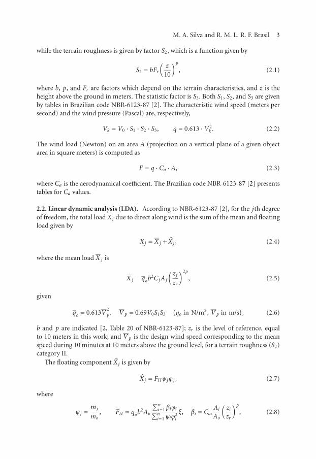
while the terrain roughness is given by factor S2, which is a function given by
S2 = bFr(z
10
)p, (2.1)
where b, p, and Fr are factors which depend on the terrain characteristics, and z is theheight above the ground in meters. The statistic factor is S3. Both S1, S2, and S3 are givenby tables in Brazilian code NBR-6123-87 [2]. The characteristic wind speed (meters persecond) and the wind pressure (Pascal) are, respectively,
Vk =V0 · S1 · S2 · S3, q = 0.613 ·V 2k . (2.2)
The wind load (Newton) on an area A (projection on a vertical plane of a given objectarea in square meters) is computed as
F = q ·Ca ·A, (2.3)
where Ca is the aerodynamical coefficient. The Brazilian code NBR-6123-87 [2] presentstables for Ca values.
2.2. Linear dynamic analysis (LDA). According to NBR-6123-87 [2], for the jth degreeof freedom, the total load Xj due to direct along wind is the sum of the mean and floatingload given by
Xj = X j + X j , (2.4)
where the mean load X j is
X j = qob2CjAj
(zjzr
)2p
, (2.5)
given
qo = 0.613V2p, V p = 0.69V0S1S3
(qo in N/m2, V p in m/s
), (2.6)
b and p are indicated [2, Table 20 of NBR-6123-87]; zr is the level of reference, equalto 10 meters in this work; and V p is the design wind speed corresponding to the meanspeed during 10 minutes at 10 meters above the ground level, for a terrain roughness (S2)category II.
The floating component X j is given by
X j = FHψjϕj , (2.7)
where
ψj =mj
mo, FH = qob2Ao
∑ni=1βiϕi∑ni=1ψiϕ
2i
ξ, βi = Cai AiAo
(zizr
)p, (2.8)

4 Nonlinear dynamic analysis
mi, m0, Ai, A0, ξ, and Cai being, respectively, the lumped mass at the ith degree of free-dom, a reference mass, the equivalent area at the ith degree of freedom, a reference area,the dynamic amplification coefficient [2, Figure 17 of NBR-6123-87], and the area Aiaerodynamical coefficient.
Note that ϕ = [ϕi] is a given mode of vibration. To compute ϕi and ξ, it is necessaryto consider the structure mass and stiffness. The lumped mass can be easily calculatedby summing the mass around an influence region of the node. The total homogenizedmoment of inertia of the cross-section is given by
Itotal = Ic + Ishom, where Ishom=Is(EsEc sec
−1)
, Ec sec=0.9× 6600√fck+3.5 (MPa),
(2.9)
Es, Ec sec, Is, Ishom, Ic, and fck being, respectively, the elasticity modulus of steel, the secantelasticity modulus of concrete (NBR-6118-78 [3]), the moment of inertia related to thestructure axis of the total longitudinal steel area, the homogenized moment of inertia ofthe longitudinal steel area, the moment of inertia of the total cross-section area, and thecharacteristic compressive resistance in MPa at 28 days concrete. Since this model is basedon linear dynamic models, we consider the cross-section moment of inertia as the totalstiffness, such as
I = Itotal, (2.10)
of each section to compute stiffness matrix of the structure. This assumption may be jus-tified because if this is a linear elastic model, any cross-section damage can be consideredin this analysis, so the stiffness to be considered must be the total stiffness.
When r modes are considered in the analysis, the combination of these modes, for agiven dynamic variable Q, is computed as
Q =[ r∑k=1
Q2i
]1/2
, (2.11)
and
Yi = 13Xi (2.12)
is a transversal dynamic load.
2.3. Nonlinear dynamic analysis (NDA). As stated before, the loads due to the windspeed present two components: the static loads due to mean wind speed and the dynamicloads due to the floating wind speed. The static loads are computed as given in (2.5)and (2.6). We call the first results obtained using these equations as the first-order staticinternal loads. At this point, we consider that the structure under those static loads issubjected to the P-Delta effect. The static displacements (δi( j)) at the ith node and thejth iteration of the P-Delta method are computed considering the effective stiffness. Dif-ferently of what occurs in Section 2.2, we consider the following expressions to compute

M. A. Silva and R. M. L. R. F. Brasil 5
the moment of inertia (Brasil and Silva [1]) at the ith node and the jth iteration of theP-Delta method:
Ii( j) = IEFi( j) =wi( j)Itotal i, where wi( j) =w(xi( j)
), xi( j) =
Mki( j−1)
Mui, (2.13)
IEF , w, x, Mk, and Mu being, respectively, the effective moment of inertia, the parameterof effective stiffness, the level of strength, the working bending moment due to meanwind speed, and the ultimate code-based moment of a given cross-section. In (2.13) weconsider the damage that occurred in the cross-sections is represented by the effectivestiffness concept.
Finally, the P-Delta effect is computed, at the ith node and the jth iteration of theP-Delta method, as
ΔMki( j) = ΔNki(δi( j)− δi( j−1)
), Mki( j) =Mki( j−1) +
∑l
ΔMkl( j). (2.14)
We call the final results obtained using these equations as the second order static inter-nal loads. Considering the stiffness obtained in the final iteration of P-Delta method wecompute the modes and frequencies of the vibration of the structure and so accomplishthe dynamic analysis, as described by (2.7) and (2.8). We considered that the structuredisplaces around the equilibrium position given by the P-Delta method.
3. Structure analyzed and numerical results
The structure analyzed here is an RC telecommunication tower 40 m long and with a di-ameter of 60 cm. The structure is cylindrical with cross-section in circular ring. Propertieschange along the structure axis, because the thickness and steel area vary along the axis.The concrete used in the fabrication of the structure presents characteristic resistance( fck) at 28 days equal to 45 MPa, which represents, according to (2.9), Ec sec = 41.4GPa.We consider the elasticity modulus of the structure E = Ec sec. The concrete covering is25 mm. The concrete design resistance is fcd = 45/1.3MPa. The steel used in confectionof the structure presents fyd = 500/1.15MPa (steel design stress) and Es = 210GPa. Thestructure is discretized into 40 elements of one meter long each one. The properties areshown in Table 3.1.
In Table 3.1 we used the following notations: Node is the node number in the finiteelements method (FEM) program; Height is the level related to the ground level; Øextis the external diameter of the cross-section; Thick is the thickness of the cross-section;M is the nodal mass (lumped mass); A total is the cross-section area; Ic is the momentof inertia of the circular ring; nb is the number of longitudinal bars of the reinforcedconcrete section; øb is the diameter of longitudinal bars; As is the total longitudinal steelarea; Rb is the radius of the circle that passes along the longitudinal bars axis; Is is the totalmoment of inertia of the steel area; I total is the total homogenized moment of inertia ofthe reinforced concrete cross-section; and Is/I total = ws is the lower boundary value forw in each section.

6 Nonlinear dynamic analysis
Table 3.1. Structure properties.
NodeHeight øext Thick M A total Ic nb øb As Rb Is I total Is/I
total(m) (cm) (cm) (kgf) (cm2) (cm4) (mm) (cm2) (cm) (cm4) (cm4)
1 40 60 10 802 1521 500417 20 13 25 27 8643 535650 7%
2 39 60 10 420 1521 500417 20 13 25 27 8643 535650 7%
3 38 60 10 420 1521 500417 20 13 25 27 8643 535650 7%
4 37 60 10 420 1521 500417 20 13 25 27 8643 535650 7%
5 36 60 10 420 1521 500417 20 13 25 27 8643 535650 7%
6 35 60 10 420 1521 500417 20 13 25 27 8643 535650 7%
7 34 60 10 420 1521 500417 20 13 25 27 8643 535650 7%
8 33 60 10 420 1521 500417 20 13 25 27 8643 535650 7%
9 32 60 10 420 1521 500417 20 13 25 27 8643 535650 7%
10 31 60 13 531 1963 576678 20 13 25 27 8643 611911 6%
11 30 60 12 831 1850 560211 15 16 30 26 10483 602945 7%
12 29 60 11 473 1731 540542 15 16 30 26 10483 583275 7%
13 28 60 11 469 1716 537852 15 16 30 26 10483 580585 7%
14 27 60 11 469 1716 537852 15 16 30 26 10483 580585 7%
15 26 60 11 469 1716 537852 15 16 30 26 10483 580585 7%
16 25 60 11 469 1716 537852 16 16 32 26 11182 583434 8%
17 24 60 11 469 1716 537852 17 16 34 26 11881 586283 8%
18 23 60 11 469 1716 537852 18 16 36 26 12579 589132 9%
19 22 60 11 469 1716 537852 19 16 38 26 13278 591981 9%
20 21 60 11 469 1716 537852 20 16 40 26 13977 594830 10%
21 20 60 14 533 1973 578100 20 16 40 26 13977 635077 9%
22 19 60 15 896 2112 595395 15 20 47 26 16136 661174 10%
23 18 60 16 599 2238 608505 15 20 47 26 16136 674284 10%
24 17 60 13 520 1921 570729 16 20 50 26 17212 640894 11%
25 16 60 13 520 1921 570729 16 20 50 26 17212 640894 11%
26 15 60 13 520 1921 570729 17 20 53 26 18288 645279 12%
27 14 60 13 520 1921 570729 18 20 57 26 19364 649664 12%
28 13 60 13 520 1921 570729 19 20 60 26 20439 654050 13%
29 12 60 13 520 1921 570729 19 20 60 26 20439 654050 13%
30 11 60 13 520 1921 570729 20 20 63 26 21515 658435 13%
31 10 60 13 520 1921 570729 22 20 69 26 23667 667206 14%
32 9 60 16 599 2238 608505 22 20 69 26 23667 704981 14%
33 8 60 16 930 2249 609579 15 25 74 26 24744 710448 14%
34 7 60 17 605 2261 610622 15 25 74 26 24744 711491 14%
35 6 60 14 556 2063 589658 16 25 79 26 26394 697251 15%
36 5 60 14 556 2063 589658 16 25 79 26 26394 697251 15%
37 4 60 14 556 2063 589658 17 25 83 26 28043 703976 16%
38 3 60 14 556 2063 589658 17 25 83 26 28043 703976 16%
39 2 60 14 556 2063 589658 17 25 83 26 28043 703976 16%
40 1 60 18 628 2351 618137 17 25 83 26 28043 732455 16%
41 0 60 18 334 2351 618137 17 25 83 26 28043 732455 16%

M. A. Silva and R. M. L. R. F. Brasil 7
0
0.2
0.4
0.6
0.8
1
1.2
w
0 0.2 0.4 0.6 0.8 1 1.2 1.4
x
Silva and Brasil cubicLower boundaryUpper boundary
Figure 3.1. Effective stiffness adopted.
According to NBR-6123-87 [2], we consider the basic wind speed of V0 = 35m/s, thetopographic factor is S1 = 1, terrain roughness category IV , class B, which gives S2 ≡(b; p; Fr), and the statistic factor is S3 = 1.1. As we stated before, the wind load on anarea A is F = q ·Ca ·A, where Ca is the aerodynamical coefficient. Several equipmentsare installed on the structure, they are stairway with anti-falls cable, platform with an-tennas supports, night signer lights, protection against atmospheric discharges system,and installed antennas. The values of A and Ca are tower, 0 ≤ z ≤ 40m, A = 0.6 m2/m,and Ca = 0.6; stairways, 0 ≤ z ≤ 40m, A = 0.05 m2/m and Ca = 2; cables, 0 ≤ z ≤ 40m,A= 0.15 m2/m, and Ca = 1.2; platform and antennas supports, z = 40m, A= 1 m2, andCa = 2; antennas, z = 40m, A = 3 m2, and Ca = 1. Table 3.1 shows the nodal mass (M)and area for the structure analyzed.
Based on the results obtained by Brasil and Silva [1], in this section we adopt thefollowing equation (Figure 3.1) for the effective stiffness parameters:
w =−1.5x3 + 3.3x2− 2.5x+ 1.1, ws ≤w ≤ 1, para i= 0,1, . . . ,n. (3.1)
Note that the upper value is equal to 1.0 and lower values vary. Because of the safetycoefficients adopted materials, and design process, usually in tests structures present val-ues of x =Mk/Mu ≥ 1.0. For a 30 m structure tested by Brasil and Silva [1], the maximumvalue assumed by x was 1.33 and for other similar 40 m structure the maximum wasx = 1.53.
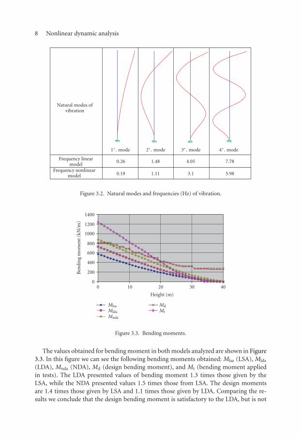
Considering the lumped mass (M) given in Table 3.1, the total homogenized momentof inertia for the LDA model, and the effective moment of inertia of the final iteration ofP-Delta method for the NDA, we compute the natural modes and frequencies of vibration(Figure 3.2). Note that in nonlinear model the frequencies are smaller than in LSA. Thecoefficient of amplification ξ presented values until 2.35 for LDA and 2.65 for NDA.
8 Nonlinear dynamic analysis
Natural modes ofvibration
Frequency linearmodel
Frequency nonlinearmodel
1◦. mode 2◦. mode 3◦. mode 4◦. mode
0.26 1.48 4.05 7.78
0.19 1.11 3.1 5.98
Figure 3.2. Natural modes and frequencies (Hz) of vibration.
0
200
400
600
800
1000
1200
1400
Ben
din
gm
omen
t(k
N/m
)
0 10 20 30 40
Height (m)
MlsaMldaMnda
MdMt
Figure 3.3. Bending moments.
The values obtained for bending moment in both models analyzed are shown in Figure3.3. In this figure we can see the following bending moments obtained: Mlsa (LSA), Mlda
(LDA), Mnda (NDA), Md (design bending moment), and Mt (bending moment appliedin tests). The LDA presented values of bending moment 1.3 times those given by theLSA, while the NDA presented values 1.5 times those from LSA. The design momentsare 1.4 times those given by LSA and 1.1 times those given by LDA. Comparing the re-sults we conclude that the design bending moment is satisfactory to the LDA, but is not

M. A. Silva and R. M. L. R. F. Brasil 9
satisfactory for NDA. Other important conclusion is about the excellent performanceof the structure related to the safety coefficient near to failure. The structure resisteda load around 1.53 times the design moment. As we stated before, this is due to the safetycoefficients applied on material strength. Results from tests show that the structure resistssatisfactorily the bending moments given by NDA.
Other important considerations here are related to the elasticity modulus of concrete.In this work we considered E = 41.4GPa, computed according to NBR-6118-78 (ABNT[3]) Brazilian code. This value is larger than the values measured in tests, around 21GPa,and larger than the value given by the revision of that code, the new NBR-6118-03 (ABNT[4]), around 31.9GPa for the adopted concrete. Tests showed that when we compute acertain functionw1(x) considering a given elasticity modulus of concrete E1 and solve theproblem again using another value E2, the new value of w is w2(x) = E1w1/E2, in otherwords, the quantity E1w1 = E2w2 = Eiwi is a constant for different values of E adopted.
4. Conclusions
In this work we propose a nonlinear dynamic model based on experimental data andthe discrete dynamic model given by NBR-6123-87 [2]. We adopted the effective stiffnessconcept to represent the physical nonlinearity and used a P-Delta method to computethe geometrical nonlinearity. We considered a cubic equation to represent the effectivestiffness. We accomplished the NDA considering the effective stiffness in function of thestrength level in each iteration of the P-Delta method. The effective stiffness obtained inthe final iteration of the P-Delta method was used to compute the natural frequencies andmodes of vibration. We considered that the structure displaces around the equilibriumposition given by the P-Delta method. Finally, we computed the sum of nonlinear staticand dynamic strength. We compared the values obtained from the NDA with those fromthe LSA and the LDA. The LDA presented values of bending moment 1.3 times thosegiven by the LSA, while the NDA presented values 1.5 times those from the LSA. Thedesign moments are 1.4 times those given by the LSA and 1.1 times those given by theLDA. We conclude that the design bending moment is satisfactory to the LDA, but is notsatisfactory for the NDA. Results from tests show that “in practice” the structure resistssatisfactorily the bending moments given by the NDA.
Suggestions for future works are(i) process this structure considering different equations for the effective stiffness;
(ii) accomplish this NDA using the synthetic wind method (Franco [5]).
References
[1] R. M. L. R. F. Brasil and M. A. Silva, RC large displacements: optimization applied to experimen-tal results, Proceedings of the Seventh International Conference on Computational StructuresTechnology, Lisbon, 2004.
[2] ABNT - Associacao Brasileira de Normas Tecnicas, NBR-6123-87: Forcas Devidas ao Vento emEdificacoes, 1987 (Portuguese).
[3] ABNT - Associacao Brasileira de Normas Tecnicas, NBR-6118-78: Projeto e Execucao de Obrasde Concreto Armado, 1978 (Portuguese).

10 Nonlinear dynamic analysis
[4] ABNT - Associacao Brasileira de Normas Tecnicas, NBR-6118-03: Projeto de Obras de Concreto,2003 (Portuguese).
[5] M. Franco, Direct Along-Wind Dynamic Analysis of Tall Structures, Boletim Tecnico da EscolaPolitecnica da Universidade de Sao Paulo, BT/PEF/9303, 1993.
Marcelo A. Silva: Department of Structures and Foundations Engineering (PEF/EPUSP),Polytechnic School, University of Sao Paulo, Rua Parnamirim 97, A24, CEP 05.331-020,Sao Paulo, BrazilE-mail address: m araujo [email protected]
Reyolando M. L. R. F. Brasil: Department of Structures and Foundations Engineering (PEF/EPUSP),Polytechnic School, University of Sao Paulo, Rua Parnamirim 97, A24, CEP 05.331-020,Sao Paulo, BrazilE-mail address: [email protected]

Submit your manuscripts athttp://www.hindawi.com
Hindawi Publishing Corporationhttp://www.hindawi.com Volume 2014
MathematicsJournal of
Hindawi Publishing Corporationhttp://www.hindawi.com Volume 2014
Mathematical Problems in Engineering
Hindawi Publishing Corporationhttp://www.hindawi.com
Differential EquationsInternational Journal of
Volume 2014
Applied MathematicsJournal of
Hindawi Publishing Corporationhttp://www.hindawi.com Volume 2014
Probability and StatisticsHindawi Publishing Corporationhttp://www.hindawi.com Volume 2014
Journal of
Hindawi Publishing Corporationhttp://www.hindawi.com Volume 2014
Mathematical PhysicsAdvances in
Complex AnalysisJournal of
Hindawi Publishing Corporationhttp://www.hindawi.com Volume 2014
OptimizationJournal of
Hindawi Publishing Corporationhttp://www.hindawi.com Volume 2014
CombinatoricsHindawi Publishing Corporationhttp://www.hindawi.com Volume 2014
International Journal of
Hindawi Publishing Corporationhttp://www.hindawi.com Volume 2014
Operations ResearchAdvances in
Journal of
Hindawi Publishing Corporationhttp://www.hindawi.com Volume 2014
Function Spaces
Abstract and Applied AnalysisHindawi Publishing Corporationhttp://www.hindawi.com Volume 2014
International Journal of Mathematics and Mathematical Sciences
Hindawi Publishing Corporationhttp://www.hindawi.com Volume 2014
The Scientific World JournalHindawi Publishing Corporation http://www.hindawi.com Volume 2014
Hindawi Publishing Corporationhttp://www.hindawi.com Volume 2014
Algebra
Discrete Dynamics in Nature and Society
Hindawi Publishing Corporationhttp://www.hindawi.com Volume 2014
Hindawi Publishing Corporationhttp://www.hindawi.com Volume 2014
Decision SciencesAdvances in
Discrete MathematicsJournal of
Hindawi Publishing Corporationhttp://www.hindawi.com
Volume 2014 Hindawi Publishing Corporationhttp://www.hindawi.com Volume 2014
Stochastic AnalysisInternational Journal of