nonlinear adaptive flight control using neural networks ... · 1 nonlinear adaptive flight control...
TRANSCRIPT
1
Nonlinear Adaptive Flight Control using Neural NetworksAnthony J. Calise∗ Rolf T. Rysdyk
Georgia Institute of TechnologySchool of Aerospace Engineering
Atlanta, GA, 30332
Abstract
Feedback linearization and adaptive neural networks provide a powerful controllerarchitecture. This paper surveys the status of nonlinear, and adaptive flight control, andsummarizes the research being conducted in this area in the School of Aerospace Engineering atthe Georgia Tech. A description of the controller architecture and associated stability analysis isgiven, followed by a more in-depth look at its application to a tiltrotor aircraft. This is followedby a summary of future research directions, and possibilities for technology transition that arecurrently underway.
Introduction
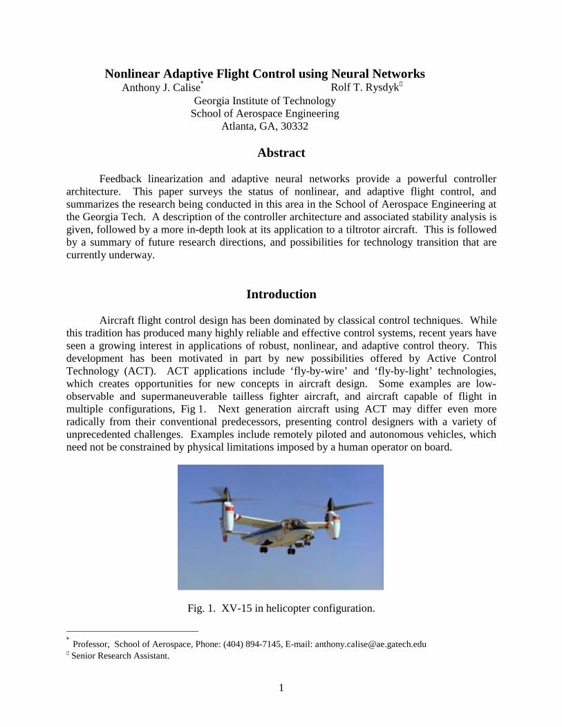
Aircraft flight control design has been dominated by classical control techniques. Whilethis tradition has produced many highly reliable and effective control systems, recent years haveseen a growing interest in applications of robust, nonlinear, and adaptive control theory. Thisdevelopment has been motivated in part by new possibilities offered by Active ControlTechnology (ACT). ACT applications include ‘fly-by-wire’ and ‘fly-by-light’ technologies,which creates opportunities for new concepts in aircraft design. Some examples are low-observable and supermaneuverable tailless fighter aircraft, and aircraft capable of flight inmultiple configurations, Fig 1. Next generation aircraft using ACT may differ even moreradically from their conventional predecessors, presenting control designers with a variety ofunprecedented challenges. Examples include remotely piloted and autonomous vehicles, whichneed not be constrained by physical limitations imposed by a human operator on board.
Fig. 1. XV-15 in helicopter configuration.
∗ Professor, School of Aerospace, Phone: (404) 894-7145, E-mail: [email protected] Senior Research Assistant.
2
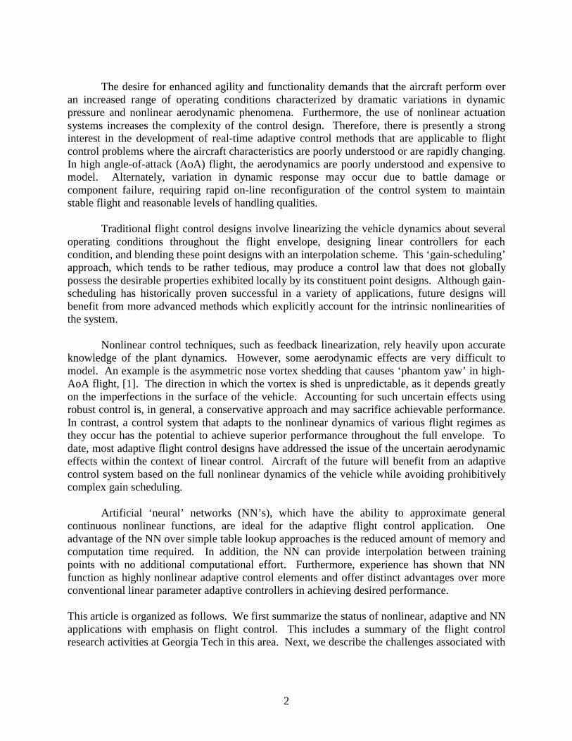
The desire for enhanced agility and functionality demands that the aircraft perform overan increased range of operating conditions characterized by dramatic variations in dynamicpressure and nonlinear aerodynamic phenomena. Furthermore, the use of nonlinear actuationsystems increases the complexity of the control design. Therefore, there is presently a stronginterest in the development of real-time adaptive control methods that are applicable to flightcontrol problems where the aircraft characteristics are poorly understood or are rapidly changing.In high angle-of-attack (AoA) flight, the aerodynamics are poorly understood and expensive tomodel. Alternately, variation in dynamic response may occur due to battle damage orcomponent failure, requiring rapid on-line reconfiguration of the control system to maintainstable flight and reasonable levels of handling qualities.
Traditional flight control designs involve linearizing the vehicle dynamics about severaloperating conditions throughout the flight envelope, designing linear controllers for eachcondition, and blending these point designs with an interpolation scheme. This ‘gain-scheduling’approach, which tends to be rather tedious, may produce a control law that does not globallypossess the desirable properties exhibited locally by its constituent point designs. Although gain-scheduling has historically proven successful in a variety of applications, future designs willbenefit from more advanced methods which explicitly account for the intrinsic nonlinearities ofthe system.
Nonlinear control techniques, such as feedback linearization, rely heavily upon accurateknowledge of the plant dynamics. However, some aerodynamic effects are very difficult tomodel. An example is the asymmetric nose vortex shedding that causes ‘phantom yaw’ in high-AoA flight, [1]. The direction in which the vortex is shed is unpredictable, as it depends greatlyon the imperfections in the surface of the vehicle. Accounting for such uncertain effects usingrobust control is, in general, a conservative approach and may sacrifice achievable performance.In contrast, a control system that adapts to the nonlinear dynamics of various flight regimes asthey occur has the potential to achieve superior performance throughout the full envelope. Todate, most adaptive flight control designs have addressed the issue of the uncertain aerodynamiceffects within the context of linear control. Aircraft of the future will benefit from an adaptivecontrol system based on the full nonlinear dynamics of the vehicle while avoiding prohibitivelycomplex gain scheduling.
Artificial ‘neural’ networks (NN’s), which have the ability to approximate generalcontinuous nonlinear functions, are ideal for the adaptive flight control application. Oneadvantage of the NN over simple table lookup approaches is the reduced amount of memory andcomputation time required. In addition, the NN can provide interpolation between trainingpoints with no additional computational effort. Furthermore, experience has shown that NNfunction as highly nonlinear adaptive control elements and offer distinct advantages over moreconventional linear parameter adaptive controllers in achieving desired performance.
This article is organized as follows. We first summarize the status of nonlinear, adaptive and NNapplications with emphasis on flight control. This includes a summary of the flight controlresearch activities at Georgia Tech in this area. Next, we describe the challenges associated with

3
modern tiltrotor technology, and illustrate the application of a NN to this research area. This isfollowed by discussions on future research directions, and possibilities for technology transition.
Status of Current Research Efforts
Nonlinear Adaptive Flight ControlThe most widely studied approach to nonlinear control involves the use of nonlinear
transformation techniques and differential geometry. This methodology transforms the stateand/or control of the nonlinear system such that the resulting system exhibits linear dynamics.Linear tools can then be applied and subsequently converted back into the original coordinatesvia an inverse transformation. This broad class of techniques is most commonly known as‘feedback linearization’. Isidori provides a comprehensive treatment of nonlinear transformationcontrol techniques [2].
Feedback linearization theory has found many applications in flight control research.Meyer and Cicolani included the concept of a nonlinear transformation in their formal structurefor advanced flight control [3]. Menon et-al., used a two-time-scale approach to simplify thelinearizing transformations [4]. A specific case of feedback linearizing control, known as‘dynamic inversion’, has been investigated at great length for application to supermaneuverableaircraft [5,6,7]. These studies show that dynamic inversion is an effective way of compensatingfor the nonlinearities associated with high AoA flight.
As illustrated by Brinker and Wise, dynamic inversion can be vulnerable to modelingerrors [8]. Therefore, a variety of robust nonlinear control schemes has been proposed. Thesetechniques provide robustness to sources of uncertainty, which typically include unmodeleddynamics, parametric uncertainty, and uncertain nonlinearities [8,9,10].
One approach to the control of nonlinear systems, which does not rely on inversion, is theclass of so-called ‘backstepping’ techniques [11]. Backstepping employs Lyapunov synthesis torecursively determine nonlinear controller for linear or nonlinear systems with a particularcascaded structure. The backstepping paradigm affords the control designer greater freedom inchoosing the form of the feedback control [12,13].
Many of the results in adaptive control are derived from Lyapunov stability theory [14].Although adaptive control has a long history, it did not gain favor until 1980, when importantresults guaranteeing closed-loop stability were obtained [15]. Parameter adaptive controlschemes may be divided into direct and indirect methods. Indirect adaptive control involves on-line identification of plant parameters, based upon which a suitable control law is implemented.In case of direct adaptive control, the parameters defining the controller are updated directly.Several efforts concentrate specifically on adaptive control of feedback-linearizable systems[16,17].
The sensitivity of some adaptive schemes to disturbances and unmodeled dynamicsprompted many researchers to investigate robust adaptive control for linear systems. Possibletools include the use of a dead-zone to maintain bounded errors in the presence of noise [18],

4
parameter projection techniques to provide robustness to unmodeled dynamics [19], and methodsfor improving robustness of adaptive nonlinear controllers using backstepping [20]. Whiletreatment of disturbances and uncertain nonlinear functions has become somewhat common,fewer efforts have addressed robustness to unmodeled dynamics. Some exceptions include anapplication of robust adaptive nonlinear control to a high-performance aircraft [21], and ademonstration of the versatility of the backstepping design paradigm [22].
Neural Networks for Flight ControlBecause of their well known ability to approximate uncertain nonlinear mappings to a
high degree of accuracy, NN’s have come to be seen as a potential solution to many outstandingproblems in adaptive and/or robust control of nonlinear systems [23,24]. The literature includesnumerous applications of NN’s to flight control systems, a selection of which will be discussedhere. Baron et al., employed polynomial networks for fault detection and reconfigurable flightcontrol [25]. Linse and Stengel demonstrated that NN’s could be used to identify aerodynamiccoefficients [26]. Applications in which NN’s are used to control supermaneuverable aircraft aredescribed by Baker and Farrell [27], and by Steck and Rokhasz [28]. Survey papers commentingon the role of NN technology in flight control system design have been contributed by Werbos[29] and Steinberg [30,31].
Our research has focused on the use of a direct NN based adaptive control architecturethat compensates for unknown plant nonlinearities in a feedback linearizing control framework.Examples in the area of fighter aircraft flight control include [32,33]. Applications to advancedtechnology guided missiles and guided munitions have been treated in [34,35,36]. In [35], theissue of robustness to unmodeled actuator dynamics is treated by modifying the adaptation law.The modification uses the concept of dynamic nonlinear damping [12], which to our knowledgeis the first time this has been developed for fully nonlinear adaptive systems. In [37], a stableadaptive algorithm is developed for multi-layer neural networks, applicable to general nonlinearsystems (nonlinear both in states and controls). Robustness to actuator dynamics for this moregeneral case is a topic of current research interest.
Fig.2. R-50 helicopter control application.
Examples of applications to helicopters and tiltrotors may be found in [3839-4041]. Inparticular, we highlight an application to the XV-15 tiltrotor aircraft in the next section of thispaper. In addition to these theoretical and application efforts, we have an experimental flight
5
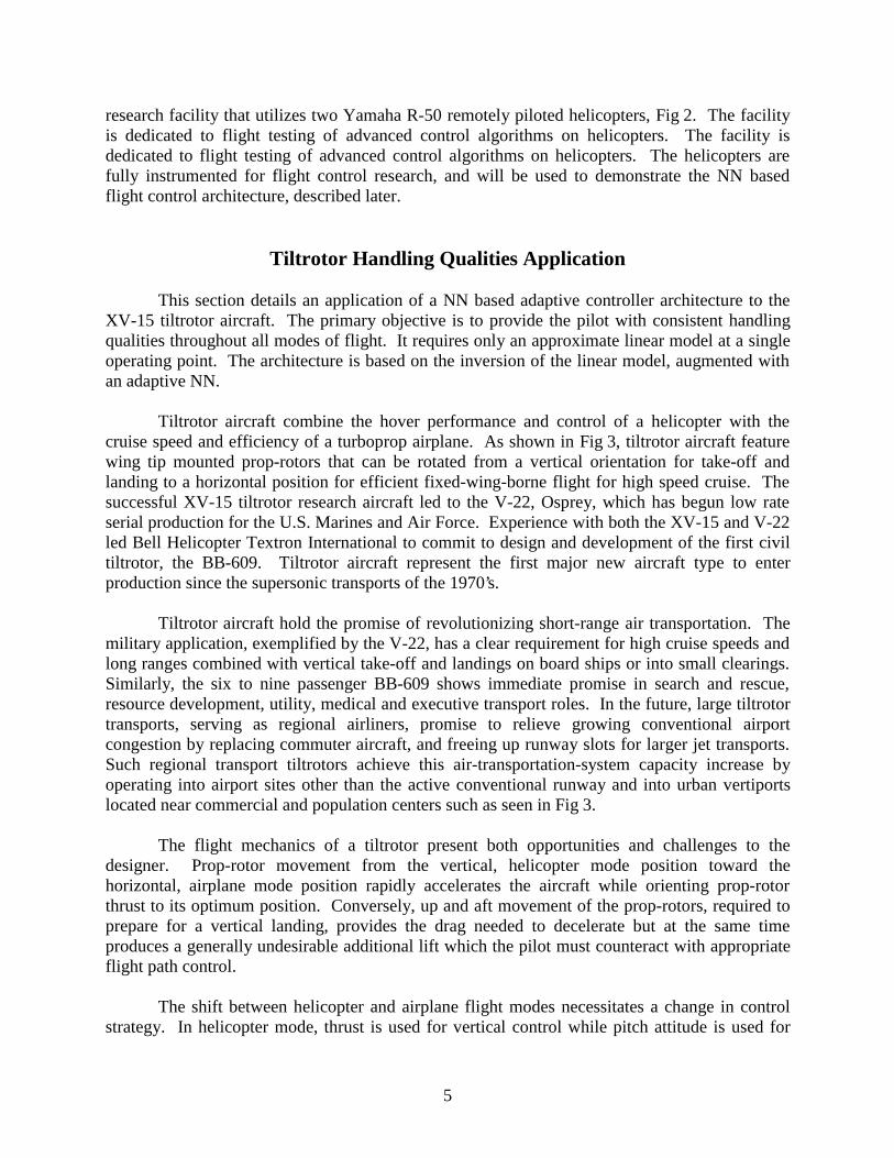
research facility that utilizes two Yamaha R-50 remotely piloted helicopters, Fig 2. The facilityis dedicated to flight testing of advanced control algorithms on helicopters. The facility isdedicated to flight testing of advanced control algorithms on helicopters. The helicopters arefully instrumented for flight control research, and will be used to demonstrate the NN basedflight control architecture, described later.
Tiltrotor Handling Qualities Application
This section details an application of a NN based adaptive controller architecture to theXV-15 tiltrotor aircraft. The primary objective is to provide the pilot with consistent handlingqualities throughout all modes of flight. It requires only an approximate linear model at a singleoperating point. The architecture is based on the inversion of the linear model, augmented withan adaptive NN.
Tiltrotor aircraft combine the hover performance and control of a helicopter with thecruise speed and efficiency of a turboprop airplane. As shown in Fig 3, tiltrotor aircraft featurewing tip mounted prop-rotors that can be rotated from a vertical orientation for take-off andlanding to a horizontal position for efficient fixed-wing-borne flight for high speed cruise. Thesuccessful XV-15 tiltrotor research aircraft led to the V-22, Osprey, which has begun low rateserial production for the U.S. Marines and Air Force. Experience with both the XV-15 and V-22led Bell Helicopter Textron International to commit to design and development of the first civiltiltrotor, the BB-609. Tiltrotor aircraft represent the first major new aircraft type to enterproduction since the supersonic transports of the 1970’s.
Tiltrotor aircraft hold the promise of revolutionizing short-range air transportation. Themilitary application, exemplified by the V-22, has a clear requirement for high cruise speeds andlong ranges combined with vertical take-off and landings on board ships or into small clearings.Similarly, the six to nine passenger BB-609 shows immediate promise in search and rescue,resource development, utility, medical and executive transport roles. In the future, large tiltrotortransports, serving as regional airliners, promise to relieve growing conventional airportcongestion by replacing commuter aircraft, and freeing up runway slots for larger jet transports.Such regional transport tiltrotors achieve this air-transportation-system capacity increase byoperating into airport sites other than the active conventional runway and into urban vertiportslocated near commercial and population centers such as seen in Fig 3.
The flight mechanics of a tiltrotor present both opportunities and challenges to thedesigner. Prop-rotor movement from the vertical, helicopter mode position toward thehorizontal, airplane mode position rapidly accelerates the aircraft while orienting prop-rotorthrust to its optimum position. Conversely, up and aft movement of the prop-rotors, required toprepare for a vertical landing, provides the drag needed to decelerate but at the same timeproduces a generally undesirable additional lift which the pilot must counteract with appropriateflight path control.
The shift between helicopter and airplane flight modes necessitates a change in controlstrategy. In helicopter mode, thrust is used for vertical control while pitch attitude is used for

6
velocity control. In airplane mode, these roles are exchanged, with thrust controlling airspeedand pitch attitude controlling vertical flight path angle. The exchanging uses of pitch attitudeand thrust control combined with gross changes in aircraft response with flight condition presentchallenges to control system design. Current tiltrotor design practice provides a continuouslyactive set of airplane controls (elevator, ailerons and rudders). Helicopter mode prop-rotorcontrols include collective pitch for thrust and power control and cyclic pitch for prop-rotor tilt.The helicopter rotor cyclic pitch controls are phased out at nacelle angles below 60 degrees.
Fig 3: Tiltrotor configurations and applications.
Command AugmentationThe wide range of flight dynamics with flight mode and condition, coupled with a variety
of desired control response characteristics depending on the flight task provides an excellentopportunity for the application of adaptive flight control laws. Two common types of controlaugmentation for aircraft are referred to as Rate Command Attitude Hold (RCAH) and AttitudeCommand Attitude Hold (ACAH), [42]. Tactical military flight and day-visual civil flight tendtoward a desire for angular rate response. As the visual cue environment degrades and flightpath precision requirements increase as with civil ‘instrument flight rules’ (IFR), the need fortighter attitude control emerges. Codified for the military in ADS-33, [42], and recommended bythe bulk of vertical flight aircraft handling qualities studies, this leads to a need for attitudestabilization and even attitude control for precise hovering and low speed flight in poor visibilityconditions. Attitude command in pitch, roll and yaw (heading) are recommended for poorvisibility hover control. As speed increases, the need for more roll maneuverability emerges,leading to a relaxation of roll control to a rate response type. Similarly, the desired control in

7
yaw axis changes from heading command to yaw rate control with turn coordination. Theconsiderations involved in a tiltrotor IFR approach procedure, include [43]:1. a conversion schedule of nacelle angle with speed, from cruise to helicopter configuration in
the approach, and vice versa for the missed approach procedure,2. deployment or retraction of flaps depending on nacelle angle, speed, and glide slope,3. switching between augmentation types, and4. desired altitude and speed trajectories.
The tiltrotor poses a unique demand on the human operator since the control responsechanges as it converts from forward flight in cruise configuration to slow flight as a helicopter.Starting in airplane configuration, the throttle affects flight speed and the longitudinal control(“cyclic” or “stick”) is used to initiate climb or descend. As the aircraft decelerates and convertsinto a helicopter configuration these controls trade roles. The throttle now represents the“collective”, controlling climb and descend directly, the longitudinal control results in changes inspeed. In all flight conditions, the primary effect of longitudinal control is a change in pitchattitude. The attitude response to a longitudinal control input is therefore of considerableinterest.
Neural Network Augmented Model Inversion ArchitectureThis section details the architecture of the NN augmented model inversion as applied to
the tiltrotor aircraft. Fig 4 contains a diagram of the architecture used for implementation ofACAH control in the pitch channel. The command filter serves both to limit the input rate, andas a model for desired response. This allows for straightforward implementation of ADS-33handling qualities specifications. The presented architecture provides for excellent results in thelongitudinal application, as is shown in following sections. Identical construction applies to thelateral channels. Results in the lateral channels show similar performance.
-
θ C O M
&&θ C
~Θ
com
man
dfi
lter U C
$δ LON$f −1 AircraftU ( )θ
neuralnet
bias
Θ =
θθ&
scaling
-U AD
X
X
XΘ C
U
linearcontroller
Fig.4. Adaptive NN augmented model inversion architecture,in the longitudinal channel, configured for ACAH.
Dynamic model inversion is used as the feedback linearization method of choice. Thetrue aircraft is represented by the GTRS nonlinear model for the XV-15 [44]. The model

8
inversion control is based on dynamics linearized about a nominal operating point, with the rotordynamics residualized, Eqn 1.
&ω ω δ= ⋅ + ⋅ + ⋅A A B1 1 2x (1)
where A1 , A2 and B represent respectively the aerodynamic stability and control derivatives at
the nominal operating point, and ω = [ ]p q r T , contains the rates about the body fixed axes[45]. The collective / throttle control position is treated as one of the relatively slow translational
states, [ ]x1 = u v w COL
Tδ . The inputs of interest are the controls of moments about the
body axes, [ ]δ = δ δ δLAT LON DIR
T.
One of the objectives of this section is to demonstrate how the NN is capable of adaptingto errors caused by the linearized inverted model. Unmodeled dynamics originate from thelinearization used in the derivation of the nominal inverting controller. This includeslinearization of dynamics nonlinear in the control. Any cross-coupling between fast rotationalstates and slow translational states is neglected in the inversion as well.
We consider inversion control using Eqn 1. This involves replacing the left-hand side ofthe equation with desired angular accelerations ( &ω D ), and solving for the control perturbations.From a generalization of the control architecture in Fig 4, the ‘pseudo control’, U , for the threerotational degrees of freedom is designed in terms of body angular rates as
U U UC C AD= + −&ω (2)
where U C is the output of a linear controller operating on an error signal. U C is used to specifythe tracking error transient, which is designed to be fast relative to the dynamics of the commandfilter, yet slow relative to the actuator dynamics. Integral action is added to provide for attituderetention in a RCAH system. For example, in the roll-channel
U K p K p dC P It
t
= ⋅ + ⋅ ∫~ ~ τ0
(3)
where ~p p pC= − . A similar representation is made for the directional channel. The potentialfor integrator wind-up is an issue of current research. To implement ACAH in the longitudinalchannel, assuming control of the Euler angle, the linear controller can be designed as
U K KC P D= ⋅ + ⋅~ ~&θ θ (4)
The signal &ω C is constructed from the command filter output as
[ ]& & && &ω C C C Cp r= θT
(5)

9
For the civilian tiltrotor application, the focus is on the approach to landing phase offlight. The combination of conversion and approach procedure calls for attitude stabilization inall channels. The need for precision during the final stages of flight benefits from ACAH in thelongitudinal channel, yet the roll and yaw channels are RCAH. By using the relations betweenthe Euler angular accelerations and the body angular accelerations, the desired acceleration canbe solved for. The elements of the desired acceleration, & [ & & & ]ω D D D D
Tp q r= , for thiscombination are
&
&
&
( )
( )
p Uq U U
r U
D p
D ( ) (r)
D r
== ⋅ ⋅ ⋅ ⋅
⋅ ⋅ ⋅ ⋅ ⋅ ⋅ ⋅ ⋅ ⋅ ⋅ ⋅=
θ φ φ φ
φ θ φ φ θ φ θ
c + + + +
+ +
t p q t p r
2 q r s t q q s t t r r c t(6)
where sφ is shorthand for sin( ),φ etc.
Substitution of &ω D in Eqn 1 and inverting results in
δ ω ω= ⋅ − ⋅ − ⋅−B A AD1
1 1 2 & x (7)
Because in practice A1 , A2 , and B are not represented nor known exactly, we actually obtain
$ $ & $ $ δ ω ω= ⋅ − ⋅ − ⋅−B A AD1
1 1 2x (8)
The inversion error is defined as
ε ω ω δ& & $ $ $ $= − ⋅ + ⋅ + ⋅A A B1 1 2x (9)
Notice, by combination of Eqn 10, and 11, that ε can be represented as a function of the statesand the pseudo control. In particular in the pitch channel, the error is a function of U ( )θ andU r( ) . The effect of ε can be represented about the body-fixed axes as
& &
& &
& &
( ) ( )
( ) ( )
( ) ( )
p
q
r
D
D
D
= += += +
ω εω εω ε
1 1
2 2
3 3
(10)
Specifically, for the ACAH implementation in the longitudinal channel we may represent theeffect of ε in the Euler pitch attitude dynamics as
&& ( ) ( ) ( )θ φ φθ= + −⋅ ⋅U c sε ε2 3 (11)
Closing the loop by combining Eqn 2, 4, and 11 we obtain
10
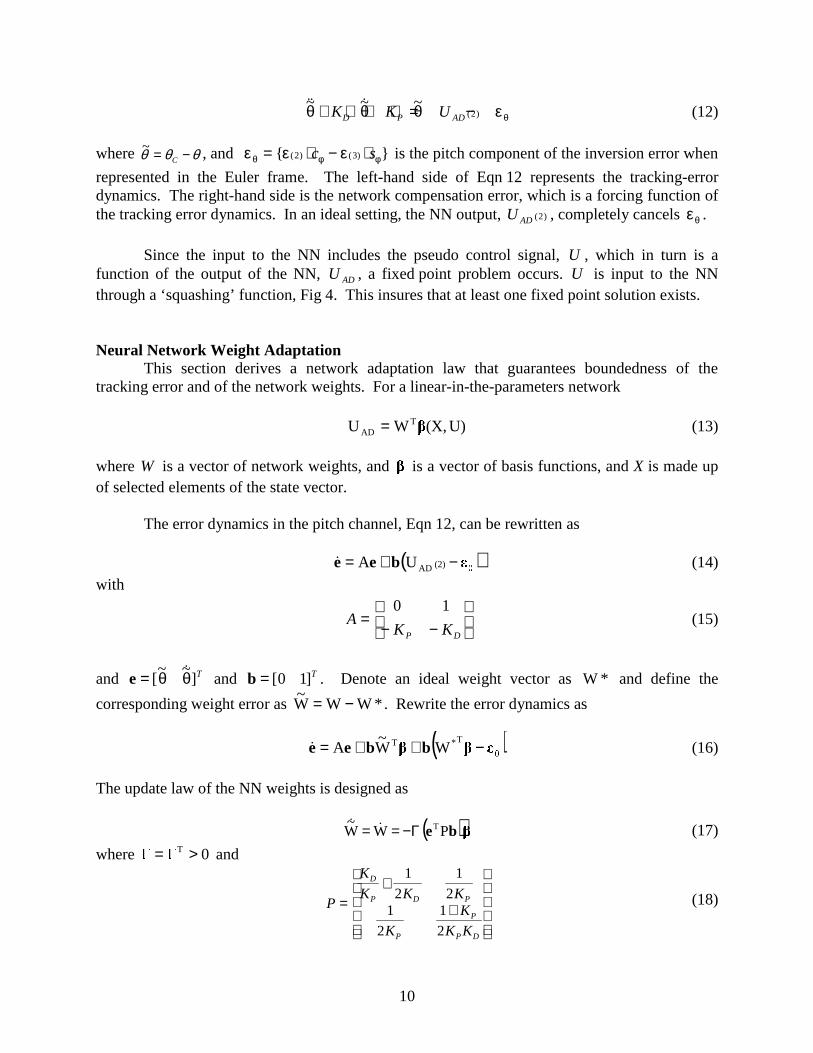
~&& ~& ~( )θ θ θ θ+ ⋅ + ⋅ = −K K UD P AD 2 ε (12)
where ~θ θ θ= −C, and ε ε εθ φ φ= ⋅ − ⋅ ( ) ( )2 3c s is the pitch component of the inversion error when
represented in the Euler frame. The left-hand side of Eqn 12 represents the tracking-errordynamics. The right-hand side is the network compensation error, which is a forcing function ofthe tracking error dynamics. In an ideal setting, the NN output, U AD ( )2 , completely cancels εθ .
Since the input to the NN includes the pseudo control signal, U , which in turn is afunction of the output of the NN, U AD , a fixed point problem occurs. U is input to the NNthrough a ‘squashing’ function, Fig 4. This insures that at least one fixed point solution exists.
Neural Network Weight AdaptationThis section derives a network adaptation law that guarantees boundedness of the
tracking error and of the network weights. For a linear-in-the-parameters network
U)(X,WU TAD = (13)
where W is a vector of network weights, and is a vector of basis functions, and X is made upof selected elements of the state vector.
The error dynamics in the pitch channel, Eqn 12, can be rewritten as
( )(2)ADUA bee −+=& (14)
with
AK KP D
=− −
0 1(15)
and T]~~
[ θθ= &e and b = [ ]0 1 T . Denote an ideal weight vector as *W and define the
corresponding weight error as *WWW~ −= . Rewrite the error dynamics as
( )T*T WW~
A bbee −++=& (16)
The update law of the NN weights is designed as
( )be PWW~ TΓ−== && (17)
where 0T >= and
P
K
K K K
K
K
K K
D
P D P
P
P
P D
=+
+
1
2
1
21
2
1
2
(18)

11
Suppose that, in a domain ' of z, the ideal weight brings the term T*W to within a
∆ -neighbourhood of the error , and that ∆ is bounded by
)()(Wsup *T* zzz
−≡ (19)
where [ ]TTT U,X=z . Note that W* can be defined to be the value of W that minimizes ∆* over
'. Let [ ]TTT W
~e=ζ and define
r :Br ≤ζζ= (20)
Let α be defined (Fig 5) by
P:B Tr ≤′∈= (21)
where( )Prmin 2T
r′λ=ζ′ζ=
=ζP (22)
and
Γ
=′ −10
0PP (23)
r
α
Ω
' rB
Fig 5: Geometric representation of sets in the theorem.
Theorem: If 0 )W ∈ and if the domain ' of z is sufficiently large, such that '⊂rB ,
where
)P(
(P)4 32*
′>r (24)
then all the signals in the system defined by Eqn’s 16 and 17 will remain bounded. Furthermore,if 0* ≡∆ then the tracking error is asymptotically stable.

12
Proof: A proof is included in the Appendix.
Remark 1: In the case wIγ= , where Iw is the unity matrix matching the dimension of
W~
, if 1(P)−> which is generally the case for reasonable values for pK and dK then Eqn 24
reduces to*232 (P)4r γ> (25)
Remark 2: The adaptation law in Eqn 17 is improved by the addition of ane-modification term [46]. This prevents parameter drift in the absence of persistent excitation.The modified update law is then implemented with µ > 0 as
( ) WPPWW~ TT bebe +−== && (26)
With W a known upper bound for *W , a Lyapunov analysis then leads to
( ) 2*32 W
~WW
~(P)4r −+γ> (27)
Remark 3: The command signals are assumed to be bounded. The effect of thecommand signal can be pictured by a geometric representation of the intersection of the sets withthe e-subspace, depicted in Fig 6. This figure shows that larger magnitude commands implysmaller values for r , and therefore smaller values for γ .
e'
~&
~
C&
C
rreB
2
Fig 6: Geometric representation of effect of r(γ) on the allowable commands.
Neural Network StructureThe NN can consist of any linearly parameterized feedforward structure that is capable of
approximately reconstructing the inversion error. Ref. [24] uses Radial Basis Functions (RBFs)because these functions are universal approximators even when the network is linearlyparameterized. However, it is well know that RBFs are very poor at interpolation between their

13
design centers, and a large number of such basis functions are needed for networks with multi-dimensional input vectors. In Ref [32], RBFs were used to capture variations in Mach number,because in the transonic region, these variations are difficult to represent by polynomialfunctions.
In the current implementation, a single-layer sigma-pi network is used. The inputs to thenetwork consist of the state variables, the pseudo control and a bias term. Fig 7 shows a generaldepiction of a sigma-pi network. The values vi represent the weights associated with a nestedkronecker product of input signal categories, and therefore they are (binary) constants. Thevalues wi are the variable network weights.
Π
Π
Π
Σ
C1
C2
C3
.1VV2
.1uwqθU(θ)
U(r)
.1θ
UAD ( )2
v1
vi
vm
w1
wn
Wkroneckerproduct
Fig.7. Neural network structure.
The input/output map of the NN for the longitudinal channel is represented as
U W X U UADT
r( ) ( ) ( )( , , )2 = β θ (28)
where X represents the normalized states. The basis functions are chosen from a sufficientlyrich set of functions so that the inversion error function can be accurately reconstructed at thenetwork output. The basis functions were constructed by grouping normalized inputs into threecategories. The first category is used to model inversion error due to changes in airspeed, sincethe stability and control derivatives are strongly dependent on dynamic pressure
C V V1201: . , , (29)
In allowing the plant to be nonlinear and uncertain in the control as well as in the states, theinversion error is a function of both state and pseudo control. These and a bias are thereforecontained in the second category

14
C u w q U U r2 01: . , , , , , , , ( ) ( )φ θ θ (30)
The third category is used to approximate higher order effects due to changes in pitch attitude.These are mainly due to the transformation between the body frame and the inertial frame
C3 01: . , , φ θ (31)
Finally, the vector of basis functions is composed of combinations of the elements of C1 , C2 ,and C3 by means of the kronecker product
β = kron kron C C C( ( , ), )1 2 3 (32)where,
( ) [ ]kron x y x y x y x ym n
T, = 1 1 1 2 L (33)
Simulation ResultsQuantitative handling quality requirements for military rotorcraft are specified in
ADS-33. The architecture as described in the preceding chapters provides guaranteed modelfollowing control. The model to be followed is easily implemented through the command filter,see Fig 8, and 9. Thus, if the model following can be guaranteed over the frequencies of interestfor handling qualities (0.2 - 6.0 rad/sec), the ADS-33 requirements can be implemented bymeans of the command filter dynamics. The Lyapunov analysis guarantees the ADS-33performance.
The Generic Tiltrotor Simulation code includes the existing XV-15 augmentation, herereferred to as ‘original SCAS’. This SCAS is gain scheduled with speed and with mast-angle. Inthe longitudinal channel, it provides ACAH and RCAH, depending on the mode selected by thepilot. The ACAH setting was used for the comparison in the following results. KP and KD werechosen so that the error dynamics settle in 0.5 second ( rad/sec6.01.0, n =− ).
1/s-
θCOM
&&θC
&θC
1/sθC
-ωn
2
ωn2
2⋅ ⋅ζ ωn
1/s-
PCOM
&PC
PCKCF
Fig.8. Pitch channel command filter. Fig.9. Roll channel command filter.
Attitude Command can be implemented as indicated in Fig 8. The dominant complexpoles of the command filter, provide minimal overshoot (ζ =.8) and a 5% settling time of1.5 seconds (ωn rad= 2 5. sec ), which provides Level 1 handling characteristics in the pitchchannel. ADS-33D prescribes Level 1 Rate Command handling qualities in roll as a havingphase bandwidth, ωBW > 2 rad/sec. With the roll-yaw coupling small the time constant of the roll
15
response is approximately the inverse of the bandwidth, so design: KCF P BW≥ ≅1 τ ω . Thisprovides the roll command filter with a 5% settling time of approximately 1.5 seconds. Thesetup for the yaw-channel is similar with a time constant, τ R = 0 25. sec . These command filterdesigns will provide Level 1 handling qualities when the augmented aircraft can indeed followthe filter dynamics up to these frequencies.
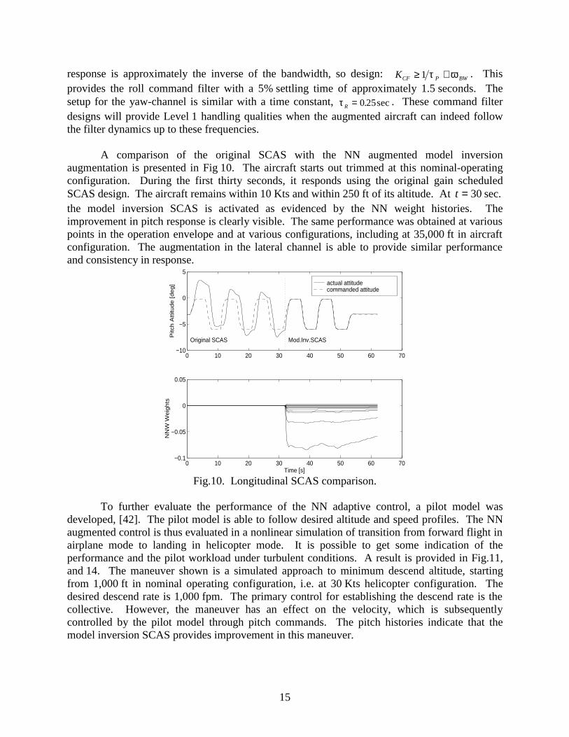
A comparison of the original SCAS with the NN augmented model inversionaugmentation is presented in Fig 10. The aircraft starts out trimmed at this nominal-operatingconfiguration. During the first thirty seconds, it responds using the original gain scheduledSCAS design. The aircraft remains within 10 Kts and within 250 ft of its altitude. At t = 30 sec.the model inversion SCAS is activated as evidenced by the NN weight histories. Theimprovement in pitch response is clearly visible. The same performance was obtained at variouspoints in the operation envelope and at various configurations, including at 35,000 ft in aircraftconfiguration. The augmentation in the lateral channel is able to provide similar performanceand consistency in response.
actual attitude commanded attitude
0 10 20 30 40 50 60 70−0.1
−0.05
0
0.05
NN
W W
eig
hts
Time [s]
0 10 20 30 40 50 60 70−10
−5
0
5
Original SCAS Mod.Inv.SCAS
Pitc
h A
ttitu
de
[d
eg
]
Fig.10. Longitudinal SCAS comparison.
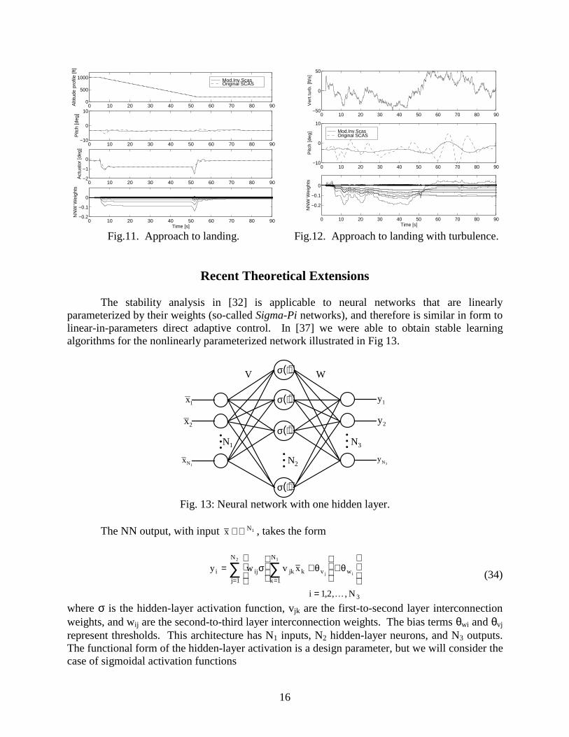
To further evaluate the performance of the NN adaptive control, a pilot model wasdeveloped, [42]. The pilot model is able to follow desired altitude and speed profiles. The NNaugmented control is thus evaluated in a nonlinear simulation of transition from forward flight inairplane mode to landing in helicopter mode. It is possible to get some indication of theperformance and the pilot workload under turbulent conditions. A result is provided in Fig.11,and 14. The maneuver shown is a simulated approach to minimum descend altitude, startingfrom 1,000 ft in nominal operating configuration, i.e. at 30 Kts helicopter configuration. Thedesired descend rate is 1,000 fpm. The primary control for establishing the descend rate is thecollective. However, the maneuver has an effect on the velocity, which is subsequentlycontrolled by the pilot model through pitch commands. The pitch histories indicate that themodel inversion SCAS provides improvement in this maneuver.
16
Mod.Inv.Scas Original SCAS
0 10 20 30 40 50 60 70 80 900
500
1000A
ltitu
de p
rofil
e [ft
]
0 10 20 30 40 50 60 70 80 90−10
0
10
Pitc
h [d
eg]
0 10 20 30 40 50 60 70 80 90−2
−1
0
Act
uato
r [d
eg]
0 10 20 30 40 50 60 70 80 90−0.2
−0.1
0
NN
W W
eigh
ts
Time [s]
Mod.Inv.Scas Original SCAS
0 10 20 30 40 50 60 70 80 90−10
0
10
Pitc
h [d
eg
]
0 10 20 30 40 50 60 70 80 90
−0.2
−0.1
0
NN
W W
eig
hts
Time [s]
0 10 20 30 40 50 60 70 80 90−50
0
50
Ve
rt.tu
rb. [ft/s]
Fig.11. Approach to landing. Fig.12. Approach to landing with turbulence.
Recent Theoretical Extensions
The stability analysis in [32] is applicable to neural networks that are linearlyparameterized by their weights (so-called Sigma-Pi networks), and therefore is similar in form tolinear-in-parameters direct adaptive control. In [37] we were able to obtain stable learningalgorithms for the nonlinearly parameterized network illustrated in Fig 13.
( )σ ⋅
( )σ ⋅
( )σ ⋅
( )σ ⋅
MM
x1
x2
xN1
M
y1
y2
yN3
V W
N2
N1 N3
Fig. 13: Neural network with one hidden layer.
The NN output, with input x N∈ℜ 1 , takes the form
y w v x
i N
i ij jk k vk
N
wj
N
j i= +
+
===
∑∑ σ θ θ11
3
12
1 2, , ,K
(34)
where σ is the hidden-layer activation function, vjk are the first-to-second layer interconnectionweights, and wij are the second-to-third layer interconnection weights. The bias terms θwi and θvj
represent thresholds. This architecture has N1 inputs, N2 hidden-layer neurons, and N3 outputs.The functional form of the hidden-layer activation is a design parameter, but we will consider thecase of sigmoidal activation functions

17
( )σ ze az
=+ −
1
1(35)
The main benefit of networks with this architecture is that they are universalapproximators, [23]. Fig 14 is taken from [37], and it illustrates a typical result based on anapplication to an advanced guided missile concept. Shown in this figure is a comparison ofresponses to a 90o AoA command using the multi-layer NN described above, with both a moreconventionally designed gain scheduled controller and an adaptive controller employing a single-layer NN. The gain scheduled linear controller (provided by Boeing Phantom Works) makes useof all the aerodynamic data, and a 3 dimensional gain schedule on altitude, mach and AoA. Theadaptive design uses only linearized aerodynamics at a single flight condition. Note that whilethe single-layer NN provides performance similar to that of the adaptive controller, the multi-layer NN is much better able to capture all the nonlinearities, and provide an essentially linearthird order response characteristic, which is the ideal response for which the design wasperformed.
command
multi−layer
single−layer
gain schedule
0 0.2 0.4 0.6 0.8 1 1.2 1.4 1.6 1.8 20
10
20
30
40
50
60
70
80
90
100
t (sec)
alph
a (d
eg)
Fig.14. Angle-of-attack step responses for several missile autopilot designs..
Another important issue concerns robustness of adaptive systems to unmodeleddynamics. The problem of robust control of nonlinear systems with input unmodeled dynamicshas been treated in [12] using the concept of nonlinear dynamic damping. In this formulation,the system is taken as linear in the control. In [35], we have extended this concept to theproblem of robust control of adaptive systems. Moreover, we have removed the restriction thatthe dynamics be linear in the control. However, the results are valid only for linearlyparameterized networks. Fig’s 15 and 16 illustrate the benefit of incorporating nonlineardynamic damping as a part of the network learning algorithm. Shown is a comparison ofresponses to filtered square wave commands for a simple pitch plane model that includesunmodeled first order actuator dynamics represented by a time constant (τ). The nominalresponse corresponds to using the network learning algorithm of [32], the robustified responseemploys the learning algorithm of [35]. Note that the nominal response is unstable for τ = 0 03. ,while the robustified response remains stable for τ = 01. . Furthermore, the response isindistinguishable from responses at smaller values of τ.

18
Future research will be focused on deriving learning algorithms for nonlinearlyparameterized networks in the presence of a class of unmodeled dynamics present at the plantinput. One approach is to combine dynamic nonlinear damping development of [35] with themulti-layer NN development of [37]. While this may provide a solution from a theoreticalperspective, it may be overly conservative to be of practical usefulness. This is because in eachsolution approach, additional terms are introduced to account separately for nonlinearparameterization and unmodeled dynamics. A more unified approach will be pursued that cansimultaneously account for these effects, and thereby lead to learning algorithms with lessconservative restrictions that need to be satisfied to guarantee global stability.
command
tau = 0.01
tau = 0.03
0 5 10 15−15
−10
−5
0
5
10
15
t (sec)
alp
ha
(d
eg
)
command
tau = 0.03
tau = 0.1
0 5 10 15−15
−10
−5
0
5
10
15
t (sec)
alp
ha
(d
eg
)
Fig.15. Nominal angle-of-attack response. Fig.16. Robustified angle-of-attack response.
Future Technology Transition
There are numerous opportunities envisioned for transitioning NN technology toapplications within the aerospace industry, besides the tiltrotor application described in aprevious section. The potential payoffs in aircraft applications include:• reduced flight control system design/development costs,• reduced costs associated with the need to develop a large aerodynamic data base,• reduction of control related accidents, and• maintenance of handling qualities immediately following failures and battle damage.
Payoffs in missile and guided munition applications include several of the abovementioned factors, and in addition:• robustness to uncertain high AoA aerodynamics (such as the ‘phantom yaw’ effects),• robustness to CG shifts and uncertain mass properties,• accommodation of variants within a class of munitions with a single control design,• improved and more predictable weapon performance, and• the potential for eliminating the need for wind-tunnel testing.

19
Aircraft Flight ControlThe NN based adaptive controller, as it presently exists, is undergoing an extensive
evaluation within an Air Force program known as RESTORE. The objective of this program isto investigate alternative approaches for designing reconfigurable flight control systems fortailless fighter aircraft. To date, the NN based approach has demonstrated that handling qualitiescan be maintained for a variety of failure modes. Boeing is currently pursuing a path totransition the RESTORE work to the X-36, Fig 17, for future flight testing.
As a result of the success thus far on the RESTORE program, Boeing has initiated a newprogram called Robust Adaptive Controller Experiment (RACE). Its goal is to develop aNN-controller for all Boeing products (aircraft, rotorcraft, missiles, munitions). The immediateapplication opportunities identified in the aircraft area include the F-18, the C-17, and unmannedaerial vehicles.
Fig.17. X-36 vehicle proposed for near-termtechnology demonstration.
Fig.18. F-18 System Research Aircraftproposed for future upgrades, including
damage adaptive flight control.
Transition opportunities to several programs exist, such as the planned F-18E/F upgrades,Fig 18, and the ‘Integrated Data Acquisition and Control System’ (IDACS) follow-on initiativesproposed in the area of improved flight safety using the Boeing C-17 aircraft. The currentlyenvisioned F-18E/F roadmap has identified new technologies such as damage adaptiveflight/propulsion controls, with a flight demonstration program in FY-01.
The goal of the IDACS program is to prevent accidents due to unexpected failures ordamage that may affect aircraft control, stability and safety. One approach entails developingand demonstrating emergency backup systems that enable damage tolerant and fault transparentflight control. One approach to achieve such a system is to do on-line system identification onthe damaged aircraft, followed by on-line redesign of the flight control system. This is the basicapproach currently being developed under this program. Our approach would eliminate the needfor system identification for purposes of control system redesign. Instead, the flight controlsystem would directly adapt to the failed condition, and fault identification would only be neededfor on-line effector management. In this setting, identification can be accomplished on a longertime scale for optimal management of the control distribution, while the adaptive systemmaintains stability and reasonable pilot handling qualities. A longer-term transition opportunity

20
is NASA’s X-33 program, which has the requirement for operational flight safety in the presenceof a single actuator failure during a mission.
Guided Missiles and Guided MunitionsAn area of particular concern in high AoA flight is vortex shedding that leads to the so-
called ’phantom yaw’ effect. The passive means proposed for mitigating this problem entailchanges to the nose cone shape that may interfere with or compromise the seeker’s ability totrack the target during the homing phase of missile guidance. Therefore, one of the majorrecommendations from a recent High Alpha workshop at Eglin AFB is that active means thatemploy either synthetic blowing at the nose tip, or other applicable micro-electro-mechanical-systems (MEMS) technology be investigated to control vortex shedding. Such controllersexhibit highly nonlinear characteristics, particularly with respect to the control action. Inaddition, it is very difficult to accurately model these effects. Therefore, highly adaptive,nonlinear control is viewed as an enabling technology for MEMS, particularly in the area ofcontrol of external flows. This will likely require extension of current research into the areas ofoutput feedback adaptive control of uncertain dynamic systems.
Conclusions
The effectiveness of a controller architecture, which combines adaptive feedforwardneural networks with feedback linearization, has been demonstrated on a variety of flightvehicles. The boundedness of tracking error and control signals is guaranteed. The architecturecan accommodate both linear-in-the-parameters networks, as well as single-hidden-layerperceptron neural networks. Both theoretical and experimental research is planned to expandand improve the applicability of the approach, and to demonstrate practical utility in the areas ofcost reduction and improved flight safety.
Acknowledgment
The authors thank Bill Decker at the NASA Ames Research Center for his support, whichincluded unpublished material on the civilian tilt-rotor project. This research supported by ARO,AFWL, AFOSR, and NASA. The authors gratefully acknowledge the feedback received fromanonymous reviewers.
Appendix
Proof of Theorem: Consider the candidate Lyapunov function
ζ′ζ=+= − PW~
W~
P)W~
,L( T1TT eee (A.1)
For KP > 0 and KD > 0 , A is Hurwitz, and for all 0>= TQQ the solution of

21
A P PA QT + = − (A.2)
is 0T >= PP . For Q I= 2 this implies Eqn 18. Differentiating Eqn A.1, substituting Eqn 16,and using Eqn A.2, gives
W~
PW~
2)*(WP2QL 1TTTTT && −++−+−= bebeee (A.3)
Substituting Eqn 17 reduces Eqn A.3 to
bee
beee
P2
)*(WP2QLT*2
TTT
+−≤−+−=&
(A.4)
Using2T (P)P eee ≤ (A.5)
it follows that
(P)P2(P)
PL T*
T
eeee +−≤& (A.6)
which is strictly negative when2
3*T (P)2P >ee (A.7)
Then rB⊂α is a positively invariant set of Eqn 16. Furthermore, define
32*Tr (P)4P:B ≤∈ζ=Ωβ ee (A.8)
If α⊂Ω , this requires that
α<3*2 (P)4 (A.9)
Then the minimum size of rB can be quantified by
)P(
(P)4r
3*22
′λ> (A.10)
and ' must be sufficiently large, so that '⊂rB .
This is sufficient to show, via the LaSalle-Yoshizawa theorem [11], that e( )t and (t)W~
remain bounded. Furthermore, if 0* ≡∆ , (no NN approximation error) then Ω reduces to the
origin and 0)(lim =∞→
tt
e . v
References
[1] K.A.Wise and D.J.Broy, “Agile Missile Dynamics and Control,” AIAA 96-3912, AIAAGuidance, Navigation and Control Conference, 1996.
[2] A.Isidori, Nonlinear Control Systems, Springer-Verlag, Berlin, 1989.

22
[3] G.Meyer and L.Cicolani, “Application of Nonlinear Systems Inverses to Automatic Flight ControlDesign System Concepts and Flight Evaluations,” AGARDograph AG-251 on Theory andApplications of Optimal Control in Aerospace Systems, NATO, pp. 10-1 to 10-29, 1980.
[4] P.K.A.Menon, G.B.Chatterji and V.H.L.Cheng, “A Two-Time-Scale Autopilot for High PerformanceAircraft,” Proceedings of the AIAA Guidance, Navigation, and Control Conference, 1991.
[5] D.J.Bugajski, D.F.Enns and M.R.Elgersma, “A Dynamic Inversion Based Control Law WithApplication to the High Angle of Attack Research Vehicle,” Proceedings of the AIAA Guidance,Navigation, and Control Conference, pp. 20-22, 1990.
[6] S.A.Snell, D.F.Enns and W.L.Garrard, “Nonlinear Inversion Flight Control for a SupermaneuverableAircraft,” AIAA Journal of Guidance, Control, and Dynamics, Vol. 15, No. 4, pp. 976-984, 1992.
[7] J.MBuffington, A.G.Sparks and S.S.Banda, “Full Conventional Envelope Longitudinal Axis FlightControl with Thrust Vectoring,” Proceedings of the American Control Conference, pp. 415-419,1993.
[8] J.S.Brinker and K.A.Wise., “Stability and Flying Qualities Robustness of a Dynamic InversionAircraft Control Law,” AIAA Journal of Guidance, Control, and Dynamics, Vol. 19, No. 6, pp.1270-1277, 1996.
[9] R.J.Adams and S.S.Banda, “An Integrated Approach to Flight Control Design Using DynamicInversion and µ-Synthesis,” Proceedings of the American Control Conference, pp. 1385-1389, 1993.
[10] J.M.Buffington, R.J.Adams and S.S.Banda, “Robust Nonlinear High Angle of Attack ControlDesign for a Supermaneuverable Vehicle,” Proceedings of the AIAA Guidance, Navigation, andControl Conference, pp. 690-700, 1993.
[11] M.Krstic, I.Kanellakopoulos and P.V.Kokotovic, Nonlinear and Adaptive Control Design, JohnWiley & Sons, Inc., New York, 1995.
[12] M.Krstic, J.Sun and P.V.Kokotovic, “Control of Feedback Linearizable Systems with InputUnmodeled Dynamics,” Proceedings of the 33rd Conference on Decision and Control, pp. 1633-1638, 1994.
[13] P.V.Kokotovic, “The Joy of Feedback: Nonlinear and Adaptive,” IEEE Control Systems, Vol. 12,No. 3, pp. 7-17, 1992.
[14] H.Khalil, Nonlinear Systems, Macmillan Publishing Company, New York, 1992.
[15] Narendra, et-al., IEEE Transactions on Automatic Control, Vol. 25, pp. 433-461, 1980.
[16] S.S.Sastry and A.Isidori, “Adaptive Control of Linearizable Systems,” IEEE Transactions onAutomatic Control, Vol. 34, No. 11, pp. 1123-1131, 1989.

23
[17] I.Kanellakopolous, P.V.Kokotovic and A.S.Morse, “Systematic Design of Adaptive Controllers forFeedback Linearizable Systems,” IEEE Transactions on Automatic Control, Vol. 36, No. 11, pp.1241-1253, 1991.
[18] B.B.Peterson and K.S.Narendra, “Bounded Error Adaptive Control,” IEEE Transactions onAutomatic Control, Vol. 27, No. 6, pp. 1162-1168, 1982.
[19] S.M.Naik, P.R.Kumar and B.E.Ydstie, “Robust Continuous-Time Adaptive Control by ParameterProjection,” IEEE Transactions on Automatic Control, Vol. 37, No. 2, pp. 182-197, 1992.
[20] Y.Zhang and P.A.Ioannou, “Stability and Performance of Nonlinear Robust Adaptive Control,”Proceedings of the 34th Conference on Decision and Control, pp. 3941-3946, 1995.
[21] S.Golpaswamy and J.K.Hedrick, “Robust Adaptive Nonlinear Control of High PerformanceAircraft,” Proceedings of the American Control Conference, pp. 1279-1283, 1990.
[22] P.V.Kokotovic and R.A.Freeman, “Robust Integral Control for a Class of Uncertain NonlinearSystems,” Proceedings of the 34th Conference on Decision and Control, pp. 2245-2250, 1995.
[23] K.Hornik, M.Stinchombe and H.White, “Multilayer Feedforward Networks are UniversalApproximators,” Neural Networks, Vol. 2, No. 5, pp. 359-366, 1989.
[24] R.M.Sanner and J.E.Slotine, “Gaussian Networks for Direct Adaptive Control,” IEEE Transactionson Neural Networks, Vol. 3, No. 6, pp. 837-863, 1992.
[25] R.L.Barron et al., “Applications of Polynomial Neural Networks to FDIE and Reconfigurable FlightControl,” Proceedings of the IEEE National Aerospace and Electronics Conference, pp. 507-519,1990.
[26] D.J.Linse and R.F.Stengel, “Identification of Aerodynamic Coefficients Using ComputationalNeural Networks,” Proceedings of the AIAA Aerospace Design Conference, Irvine, CA, 1992.
[27] W.L.Baker and J.A.Farrell, “Learning Augmented Flight Control for High Performance Aircraft,”Proceedings of the AIAA Guidance, Navigation, and Control Conference, pp. 347-358, 1991.
[28] J.E.Steck and K.Rokhasz, “Use of Neural Networks in Control of High Alpha Maneuvers,” 30thAIAA Aerospace Sciences Meeting and Exhibit, Reno, NV, 1992.
[29] P.J.Werbos, “Neural Networks and Flight Control: Overview of Capabilities and EmergingApplications,” Proceedings of the AIAA Guidance, Navigation, and Control Conference, pp. 912-919, 1995.
[30] M.Steinberg, “Potential Role of Neural Networks and Fuzzy Logic in Flight Control Design andDevelopment,” Proceedings of the AIAA Aerospace Design Conference, Irvine, CA, 1992.
[31] M.Steinberg, “An Initial Assessment of Neural Network and Fuzzy Logic Technology for FlightControl Systems,” Proceedings of the American Control Conference, pp. 173-177, 1994.

24
[32] B.S.Kim and A.J.Calise, “Nonlinear Flight Control Using Neural Networks,” AIAA Journal ofGuidance, Control, and Dynamics, Vol. 20, No. 1, pp. 26-33, 1997.
[33] A.J.Calise, S.Lee and M.Sharma, “Direct Adaptive Reconfigurable Control of a TaillessFighter Aircraft”, to be presented at the AIAA Guidance, Navigation, and ControlConference, Boston, MA, August, 1998.
[34] M.B.McFarland and A.J.Calise, “Nonlinear Adaptive Control of Agile Anti-Air MissilesUsing Neural Networks”, AIAA Missile Sciences Conference, Monterey, California,December, 1996.
[35] M.McFarland and A.J.Calise, “Robust Adaptive Control of Nonlinear Systems UsingNeural Networks”, American Control Conference, Albuquerque, NM, June, 1997.
[36] A.J.Calise and M.Sharma, “An Adaptive Autopilot Design for Guided Munitions”, to be presentedat the AIAA Guidance, Navigation, and Control Conference, Boston, MA, August, 1998.
[37] M.B.McFarland and A.J.Calise, “Multilayer Neural Networks and Adaptive Nonlinear Control ofAgile Anti-Air Missiles”, AIAA 97-3540, AIAA Guidance, Navigation, and Control Conference,1997.
[38] J.Leitner, A.J.Calise and J.V.R.Prasad, “Analysis of Adaptive Neural Networks for Helicopter FlightControls,” AIAA Journal of Guidance, Control, and Dynamics, Vol. 20, No. 5, Sept.-Oct.,pp.972-979, 1997.
[39] T.Jiang, J.V.R.Prasad and A.J.Calise, "Adaptive Fuzzy Logic Flight Controller for Rotorcraft,"AIAA 96-35729, AIAA Guidance, Navigation, and Control Conference, 1996.
[40] R.T.Rysdyk and A.J.Calise, “Adaptive Model Inversion Flight Control for Tiltrotor Aircraft”,submitted to AIAA Journal of Guidance, Control, and Dynamics.
[41] R.T.Rysdyk, A.J.Calise and R.T.N.Chen, “Nonlinear Adaptive Control Of Tiltrotor Aircraft UsingNeural Networks”, AIAA/SAE World Aviation Congress 1997 proceedings, Anaheim, CA, October1997.
[42] Aeronautical Design Standard, “Handling Qualities Requirements for Military Rotorcraft”,ADS-33D, U.S.Army, St. Louis, MO, July 1994.
[43] W.A.Decker, “Piloted Simulator Investigations of a Civil Tiltrotor Aircraft on Steep InstrumentApproaches,” AHS 48th Annual Forum, Washington, D.C., June 1992.
[44] NASA CR-166536, A Mathematical Model for Real Time Flight Simulation of a GenericTilt-Rotor Aircraft, Sept. 1988, Rev. A
[45] B.Etkin, Dynamics of Atmospheric Flight, John Wiley & Sons, New York, 1972.
[46] K.S.Narendra and A.M.Annaswamy, “A New Adaptive Law for Robust Adaptation WithoutPersistent Excitation,” IEEE Transactions on Automatic Control, Vol. 32, No. 2, pp. 134-145, 1987.