nondestructive testing' in encyclopedia of polymer ...nguyen.hong.hai.free.fr/ebooks/science...
TRANSCRIPT

Encyclopedia of Polymer Sceince and TechnologyCopyright c© 2005 John Wiley & Sons, Inc. All rights reserved.
NONDESTRUCTIVE TESTING
Introduction
Polymers are macromolecules that contain repetitive, regular or irregular ar-rangements of organic molecular groups, ie, carbon atoms covalently bonded withother carbon and/or heteroatoms. Technical polymers usually contain additives,fillers, and pigments. Polymer–matrix composites (PMC) contain at least a sec-ond, insoluble phase, frequently in the form of fibers or particles. The structureand morphology of polymers and PMC can be quite complex; see, eg, AMORPHOUS
POLYMERS; SEMICRYSTALLINE POLYMERS; MORPHOLOGY, ADDITIVES, VISCOELASTICITY,PHASE TRANSFORMATION, and Reference 1. Properties of polymers and PMC thatmay be relevant for nondestructive testing (NDT) are as follows: (1) (pronounced)temperature dependence, viscoelastic behavior, and, in some cases, specific transi-tion temperatures; (2) limited thermal stability, upper limit set by incipient decom-position or melting; (3) relatively low density; (4) transparency, semitransparency,or opaqueness with respect to the visible part of the electromagnetic spectrum; (5)electrical insulation and relatively low electrical conductivity for specially formu-lated compositions; and (6) possible changes in volume, properties, and, in somecases, even chemical reactions induced by absorption or diffusion of media.
The literature on NDT of polymers and PMC comprises the classes shownin Table 1. References illustrate the available range of literature or a specifictopic. Omission or inclusion of a reference does not imply a rating by the authors.The amount of information available in electronic format only is steadily increas-ing, eg, References 2–8, and many journals feature electronic on-line editions.Electronic database searches are sensitive to spelling, eg, “non-destructive” yields27, and “nondestructive” 384, active standards of the American Society for Test-ing and Materials International. Most NDT methods apply to various materialclasses. Those documents that explicitly mention polymers or PMC deal with ef-fects specific to certain materials, eg, the Felicity effect in PMC (9), or with polymerproducts used in large quantities (10–14). Standards tend to lag behind technicaldevelopments, as discussed for acoustic emission (15), but similar arguments holdfor other NDT methods.
Nondestructive testing (NDT) is the development and application of technicalmethods for the detection, location, measurement, and evaluation of discontinu-ities, defects and other imperfections, the assessment of integrity, the assessmentof properties and composition, or the measurement of geometrical characters with-out impairing the intended use or application of the test object (31).
1

2 NONDESTRUCTIVE TESTING
Table 1. Classes of Literature on NDT of Polymers and PMC
Source type Sample references Remarks
Handbooks (16–26) Some volumes available in 3rd edition,others in preparation; 3rd edition alsoavailable in electronic format on compactdisc with supplemental information
Monographs (27,28)Normative codesand standards
(9–14) Few codes and standards are explicitly onNDT applied to polymers and PMC, butmost NDT codes and standards areapplicable to polymers and PMC, exceptwhen explicitly stating another class ofmaterials; up-to-date information can beobtained on the Web sites ofstandards-issuing organizations, eg (2–5)
Guidelines(withoutnormativecharacter)
(29,30) A few guidelines are explicitly on NDTapplied to polymers and PMC, but mostNDT guidelines apply to polymers andPMC, except when stating explicitlyanother class of materials
Journals Electronicjournals ClassA (6,7)Class B (8)
Literature on NDT of polymers and PMCcomprises two classes (see Bibliographyfor examples):
A. journals dealing with NDTB. journals dealing with polymers and PMC
Conferenceproceedings
Class AClass B
Conferences again comprise two classes:
A. general or topical (on specific NDTmethods and/or applications) NDTconferences
B. conferences on polymers and PMC
Information on many conferences isavailable on the Internet, eg, through linkson the Web sites of national NDT societiesa
Technicaldocuments
Equipmentdescriptions,technical manuals,application notes
Provided, eg, by equipment manufacturersor test agencies
Educationaldocuments
Lecture notes,training manuals
Provided, eg, by lecturers, national NDTsocieties, NDT training and certificationagencies
aWeb sites of most national NDT societies can be found at www.icndt.org/directory.htm (however,some listings may not be up-to-date).

NONDESTRUCTIVE TESTING 3
Composites are a combination of at least two materials, insoluble in oneanother, combined to yield a material with certain properties not possessed by theconstituents (32). In PMC, polymers form a continuous constituent, called matrix,in which the other phase(s) are embedded (see COMPOSITE MATERIALS).
The distinction between “natural” and “synthetic” polymers or PMC (eg,natural versus synthetic rubber, plastics versus biopolymers, wood versusfiber-reinforced composites) is of limited relevance for the application of NDTmethods.
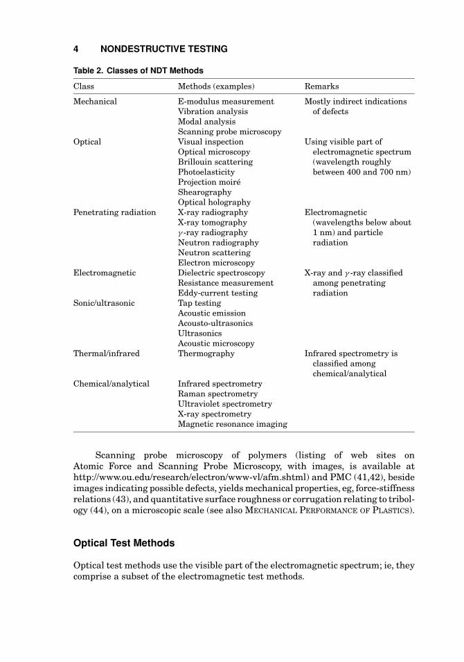
Classes of Nondestructive Test Methods. NDT methods are classi-fied according to the physical principle or effect that constitutes their base (26),corresponding to the probe-type or energy source (Table 2, the list of methods isincomplete). Each NDT method can be characterized by its type of (1) probe orenergy source, (2) interaction with the test object, (3) signal detection, (4) signalrecording, and (5) signal interpretation (26). Other categories for grouping NDTmethods are, eg, (1) “imaging” versus “nonimaging” methods, (2) “volume” versus“local” method, (3) noncontact versus contacting methods, (4) in situ versus ex situor “field” versus “laboratory” testing, (5) real-time versus post-test indication and(6) “small” or “specific” specimen size versus full-scale testing.
Mechanical Test Methods
Determination of mechanical properties is one, although indirect, way of findingindications of defects (see MECHANICAL PERFORMANCE OF PLASTICS). The elasticmodulus of polymers and PMC depends, among others, on porosity or microc-rack content. Quantitative evaluation requires comparison with specimens withknown content from destructive analysis or others (33). Qualitative, relative com-parison is feasible, but still requires careful conditioning, since mechanical prop-erties depend on humidity content and temperature. The tensile elastic modulusof samples from one batch typically yields standard deviations of 3–5% for carbonfiber-reinforced polymers (CFRP) and of 5–7% for glass fiber-reinforced polymers(GFRP). Values around 2% have been obtained for high quality CFRP laminates.
Dynamic Mechanical Analysis (qv) (DMA) or dynamic thermal mechanicalanalysis (DTMA) indicate damage in polymers or PMC (34), and aging effects inpolymers by a shift in the transition temperature (35). Limitations are the volumeof the test chamber or the required specimen shape.
Compliance, ie, the displacement-to-load ratio, is used in fracture mechanicstests to determine crack length or to monitor crack growth (36).
Vibration or modal analysis yield indications of defects in structural elementsor parts when excited by suitable loads (37) (also see SONIC AND ULTRASONIC TEST
METHODS). The literature mainly describes applications to PMC laminates, aim-ing at detecting critical delaminations (38). A relative comparison for a specificelement with time, loading, or exposure may be sufficient to find indications ofa defect or of a change in the behavior of the structure. Comparison with finiteelement calculations is one approach for quantitative evaluation (39). Recent re-search on monitoring of PMC elements or structures also investigates the use ofpiezoelectric sensors for detection of delaminations by external excitation (40).
4 NONDESTRUCTIVE TESTING
Table 2. Classes of NDT Methods
Class Methods (examples) Remarks
Mechanical E-modulus measurementVibration analysisModal analysisScanning probe microscopy
Mostly indirect indicationsof defects
Optical Visual inspectionOptical microscopyBrillouin scatteringPhotoelasticityProjection moireShearographyOptical holography
Using visible part ofelectromagnetic spectrum(wavelength roughlybetween 400 and 700 nm)
Penetrating radiation X-ray radiographyX-ray tomographyγ -ray radiographyNeutron radiographyNeutron scatteringElectron microscopy
Electromagnetic(wavelengths below about1 nm) and particleradiation
Electromagnetic Dielectric spectroscopyResistance measurementEddy-current testing
X-ray and γ -ray classifiedamong penetratingradiation
Sonic/ultrasonic Tap testingAcoustic emissionAcousto-ultrasonicsUltrasonicsAcoustic microscopy
Thermal/infrared Thermography Infrared spectrometry isclassified amongchemical/analytical
Chemical/analytical Infrared spectrometryRaman spectrometryUltraviolet spectrometryX-ray spectrometryMagnetic resonance imaging
Scanning probe microscopy of polymers (listing of web sites onAtomic Force and Scanning Probe Microscopy, with images, is available athttp://www.ou.edu/research/electron/www-vl/afm.shtml) and PMC (41,42), besideimages indicating possible defects, yields mechanical properties, eg, force-stiffnessrelations (43), and quantitative surface roughness or corrugation relating to tribol-ogy (44), on a microscopic scale (see also MECHANICAL PERFORMANCE OF PLASTICS).
Optical Test Methods
Optical test methods use the visible part of the electromagnetic spectrum; ie, theycomprise a subset of the electromagnetic test methods.

NONDESTRUCTIVE TESTING 5
Visual inspection by eye is certainly the oldest method and is widely used, butsubject to physiological limitations. Optical and electronic equipment, eg, endo-scopes originally developed for medical applications, and electronic image record-ing and processing have become standard tools for visual inspection.
Composition and/or morphology of many polymers and PMC limit NDT vi-sual inspection to surface and near-surface features. Transparent polymers andsemitransparent PMC allow for the detection of inhomogeneities, such as voids,pores, or cracks, as well as qualitative or semiquantitative estimates of fiber vol-ume fraction and/or fiber alignment. Light sources enhance sensitivity in visualthrough-thickness and surface inspection.
Standards for visual inspection of polymer products are in preparation (12).Evaluation requires experience and is operator-dependent. Indications can be doc-umented with photography. Digital photography or digitization of photographsallow for image processing and automated image analysis.
Conventional dye penetrant testing for surface crack detection in PMC isdescribed in older literature (45), but is now rarely used, except for highlightingcracks in PMC after destructive sectioning (46).
Optical microscopy has also profited from recent advances. Scanning nearfield optical microscopy (SNOM) (47) (SNOM images of polymers and other materi-als are available at, eg, http://wwwex.physik.uni-ulm.de/SNOMWeb/), eg, reachesspatial resolution at the molecular level when using fluorescent molecules, com-peting with the scanning probe methods (48). The limitations are typical specimensize and scanning area.
Using coherent or structured light to illuminate the test object can revealinformation that is not accessible to visual inspection (25,49,50). Commonly, afilm or camera is used to record this information.
Interferometric methods use laser illumination to measure surface deforma-tions under thermal, mechanical, vibration, or pressure loading (51). By virtueof the high sensitivity of a few tens of nanometer, inhomogeneities in the inter-ference fringe pattern due to cracks, delaminations, or material inhomogeneitiescan be revealed using small loads. Because the laser light is only used to recordthe information, care must be taken to set up the appropriate loading schemethat enhances the type of defect to be found. Well-known methods in compos-ite testing, especially for aerospace and spacecraft applications, are electronic ordigital speckle pattern (correlation) interferometry (ESPI or DSPI) (52–55) andshearography, also termed shearing speckle pattern interferometry (SSPI) (56).The methods are used to find indications of delaminations, voids, and cracks.Quantitative evaluation of deformation and strain is also important (57) and canbe used to measure stress concentrations, vibration modes (58,59), or material pa-rameters. By nature, the techniques discussed are surface techniques and there-fore most appropriate for surface or close-to-surface defects. However, when com-bined with transient loads, some information on the depth of a flaw can be gained(60).
(Digital) holographic interferometry (61) basically yields the same informa-tion as DSPI, but is limited because it requires a development step (photographicprocessing or numerical reconstruction) before indicating the load effect on theobject.

6 NONDESTRUCTIVE TESTING
Limitations of the interferometric techniques are due to the required me-chanical stability of the measurement head relative to the object of better than 1µm. Safety regulations for using high power lasers also have to be observed.
Structured light methods comprise shadow moire, projection moire, andfringe projection (25,62). They use a structured intensity pattern, most commonlya set of parallel fringes, to illuminate the object. A camera records the fringes onthe object surface from a triangulation angle. In moire methods (63) fine pitchgratings can be used, because the imaged fringes are demodulated by a referencegrating in front of the camera before recording. Moire methods are usually usedto measure deformations or to compare the shape of objects, eg, in production con-trol, with a resolution of roughly 1/10,000 of the field of view (64–66). The physicsof fringe projection is basically the same (67), but the fringes are directly recordedby the camera. Hence, the pitch of the grating is limited by the camera resolution.
By using a sequence of ever coarser gratings and a calibrated setup, theabsolute shape of an object is acquired with a resolution of roughly 1/1,000 of thefield of view (68).
Penetrating Radiation Test Methods
Penetrating radiation comprises electromagnetic radiation in the wavelengthrange below about 1 nm (roughly equivalent to 1 keV energy) or particle radiation.The former is generated in the electronic shell of atoms (X-rays) or by processes inthe atomic nuclei (γ -rays). Particle radiation can be generated with particle accel-erators, sometimes requiring special targets. Neutrons, eg, come from a spallationsource (69) or a nuclear reactor. X-rays are produced by electron beam impact ontargets in evacuated tubes or in accelerators by Bremsstrahlung, the “braking” ra-diation emitted by accelerated, charged particles. Ultraviolet and low energy X-rayradiation of high intensity from synchrotrons is used for analysis (70) and process-ing (71) of polymers and PMC. A list of currently operational synchrotron sourcesis available, eg, at http://www.src.wisc.edu/community/sr sources.html (see SYN-CHROTRON RADIATION).
Polymers and PMC are of relatively low density and hence do not absorbX-rays or γ -rays efficiently. “Low” energy radiation (typically 10–40 keV) yieldsenhanced contrast for X-ray radioscopy or radiography of polymers and PMC dueto the nonlinear shape of the absorption versus energy curve (72). Higher energyγ - and X-ray sources are hence less suitable.
Contrast can be enhanced by X-ray contrast agents or X-ray dye penetrants(73). These consist of high density materials, eg, liquid halogen compounds (ZnI,methylenediiodide, or diiodobutane) and are different from the dye penetrantsused in visual penetrant testing. Test objects are immersed or the contrast agent isinjected into, eg, cracks or delaminations extending to the surface of the test object.Any pore, void, crack, or delamination not extending to the surface hence escapesdetection. Sufficient wetting between contrast agent and material is importantfor complete penetration. Even then, a minimum amount of contrast agent isnecessary to obtain detectable contrast. Many commercial contrast agents (1) aretoxic or carcinogenic requiring appropriate safety measures, (2) are volatile tosome degree, limiting immersion time and imaging duration, (3) are of limited

NONDESTRUCTIVE TESTING 7
shelf live, and (4) raise concerns about inducing deleterious effects (73). There isat least one documented case of suspected dye penetrant induced microcrackingin PMC (74).
Penetration and absorption of the electromagnetic or particle radiation re-sults in energy deposition (heating) and implantation of beam particles. Energydeposition and particle irradiation may affect the microstructure and inducebreaking or formation of new molecular bonds. Examples are gamma radiationeffects (75) and cross-linking in polyethylene by electron irradiation (71). The in-tensity needed for cross-linking usually exceeds that obtained from NDT beamsources.
Conventional X-ray tubes with an energy range from 10 to 450 keV have atypical source diameter (focal spot) of a few millimeters. Microfocal X-ray sources(76) with a source diameter of about 5 to 10 µm allow for magnification in X-rayradiography by projection imaging (test object close to source, imaging system ata distance). The small source size limits the blur due to geometrical projectionwith conventional X-ray sources. Energy—microfocal X-ray sources operate up toabout 200 keV—and intensity limit the maximum distance between source andimaging system. Magnification can be up to 100 times, but frequently the sizeof details to be imaged or the maximum size of the imaging system set lowerlimits.
At energies below 40 keV, X-ray absorption in air is a major limitation, andreplacing air by low density helium has been recommended (77). This requires aspecial enclosure for X-ray source and imaging system, often limiting the size ofthe test object. X-ray beam hardening (78), ie, the preferential absorption of lowenergy X-rays in the test object, also occurs in polymers and PMC, but to a lesserextent than in denser materials.
Low X-ray intensity yields longer exposure times; for a 1-mm thick CFRPplate a G2 class X-ray film (79) (ie, a D4 class film at that time), 17–18 keV X-rayenergy, 1000 mm imaging system–focus distance, and a focus–object distance of150 mm, resulted in an exposure of about 600 s (80).
X-ray image intensifiers converting the incident X-rays into an image ona scintillating screen allow time-resolved X-ray imaging when recorded with avideo camera. Crack initiation in PMC, eg, was investigated with a microfocalX-ray source and X-ray image intensifier with 25-Hz video imaging at magnifica-tions between 5 and 10 times (81). Digitized frames of the video recording can beelectronically processed and analyzed. Conventional or X-ray film still images canalso be digitized for electronic processing (82).
X-ray radiography is moving from X-ray film to computed radiography (CR).Reusable imaging plates with 25 or 50 µm resolution are commercially available.Manufacturers data sheets indicate that up to 1000 record–erase cycles can beperformed (83). Special electronic filters may improve detection of indications.Electronic image recording and storage allow for easy processing and electronicdata transmission. However, long-term storage and readability of the recordsmay pose problems in the future. Development of standards in CR is under way(84,85).
X-ray Compton back-scattering can yield indications of delaminations inPMC without the use of contrast agents, ie, including those that do not extendto the surface. The basis is a special source–detector arrangement (86).

8 NONDESTRUCTIVE TESTING
X-ray laminography was developed for investigating specific layers of fiber-reinforced laminate sheets by multiple exposure on the same film. Recently, it hasbeen developed into a computer tomography (CT) method (87), but is rarely used.
X-ray CT with commercial CT equipment or synchrotron radiation (70) isincreasingly used in research and development, and industrial use is incipient.X-ray micro-CT yields spatial resolution of around 10–20 µm for microfocal (76)and down to 1–2 µm for synchrotron X-ray sources (88). These resolutions require“small” test objects, around a few cubic decimeters in the microfocal and a fewcubic centimeters in the synchrotron X-ray source.
X-ray refraction, based on small angle X-ray scattering (SAXS), may proveuseful in the detection of microdamage in PMC, such as crack growth (89) andfiber debonding (90). SAXS images of polymer nanocomposites are shown in Ref-erence 91. Near-edge X-ray absorption fine structure (NEXAFS) and related X-raytechniques provide information on composition and morphology of polymers on amicroscopic scale (see X-RAY MICROSCOPY).
Neutrons find various applications in the characterization of polymers andPMC (92). Neutron scattering experiments investigate structure and behavior ofpolymers at the atomic level (93). Neutron absorption as a function of the atomicnumber of the elements differs from that of X-rays, and the power of neutronradiography (94) for polymers and PMC, even combined with metals, is illustratedat, eg, http://neutra.web.psi.ch/gallery/index.html. Currently operational neutronradiography sources are listed at www.anlw.anl.gov/nr/oldindex.htm.
Positron annihilation spectroscopy (PAS) is used in research on free volume(95) or on aging effects in polymers (96), and muon spin resonance with muonbeams (97) yields information on dynamic processes in polymers (98), but specimensize may be limited.
Electron microscopy is one example of electron beam analysis of polymers andPMC. Beam charging effects occur in most polymers and PMC (99), unless whencoated with a thin conductive layer (carbon, gold, or platinum). Environmentalscanning electron microscopes (ESEM) do not require such coatings (100). Sizeand shape of the test object and possible electron beam heating effects then decidewhether the method is NDT.
Electromagnetic Test Methods
Many polymers and most PMC show no or only comparatively low electrical con-ductivity, which limits application of electromagnetic test methods. One of themain exceptions is CFRP. The continuous network of carbon fibers in CFRP al-lows for electrical resistance measurements, eg, based on the four-probe method.Electrical potential (101) or resistance methods are used in fracture mechanics todetect delaminations (102) and to monitor damage in CFRP (103). Whether theapplication of electrodes is nondestructive depends on the intended use.
Electrical conductivity measurements have also been developed as tomogra-phy (104). Eddy-current testing (ET) of CFRP laminates is feasible (105). ET isnoncontact and NDT, as long as thermal effects from resistive heating and energydissipation are sufficiently small. Superconducting quantum interference devices(SQUID) have been used for ET to detect damage in CFRP (106). However, SQUID

NONDESTRUCTIVE TESTING 9
may soon be replaced by sensors based on giant magnetoresistance (GMR) or giantmagnetoimpedance (GMI) effects (107).
Dielectric measurements are performed on polymers and PMC for researchand industrial applications, specifically to find materials with low dielectric losses(108) (see DIELECTRIC RELAXATION).
Fractoluminescence (109), ie, the emission of visible light, and electromag-netic emission from fracture of polymers or PMC (110) have not yet been investi-gated as NDT tools. Microwave testing is applicable to nonconducting materials(111) and used, eg, for exciting ultrasonic waves in PMC (112) or the character-ization of anisotropic materials, such as short fiber–reinforced injection moldedparts (113). The energy deposition due to microwave radiation, on the other hand,is applied in processing of polymers and PMC (114).
Sonic and Ultrasonic Test Methods
Sonic and ultrasonic test methods use elastic waves propagating in solid or fluidmedia and are classified into “active” and “passive” methods. The former requiresemission of waves into the test object; the latter, waves emitted by the materialitself.
Tap testing a PMC structure by hand or by a suitable instrument, an expe-rienced operator can tell whether the structure is sufficiently defect-free (115).
Acoustic emission (AE) analysis is an example of a passive method (21).Beside piezoceramic lead zirconate titanate (PZT) sensors, thin piezoelectricpoly(vinylidene fluoride) (PVDF) films (116) and noncontact interferometry (117)also sense the rapid, transient elastic waves generated inside most materials.Composites (118) made from PZT fibers have recently been characterized as AEsensors (119). AE of polymers and PMC is affected by (1) relatively large signal at-tenuation limiting the maximum distance between sensor and signal source, andmainly in PMC; (2) anisotropy, limiting location accuracy; and (3) several sourcemechanisms that can act simultaneously. In PMC, the so-called Felicity effect ie,the appearance of AE activity at the same sensitivity but lower load levels thanpreviously attained (31), forms the base of commercial AE applications in integrityassessment of PMC structures (9).
Quantitative AE analysis for characterizing damage accumulation in PMCis described in Reference 120, approaches for signal analysis and identificationof mechanisms in Reference 121, and a practical AE application to automotivecomposites in Reference 122.
Ultrasonic waves (typically in the MHz range) can be excited by piezoelec-tric transducers coupled to the test object. Electromagnetic acoustic transducers(EMAT) (123) cannot be used for ultrasonics of polymers and PMC; alternativesare discussed in Reference 124. The waves propagate and are scattered and at-tenuated in the material. The signal can be detected in either reflection or trans-mission mode (by the transducer emitting the ultrasonic pulse for reflection orby additional transducers at other locations in transmission). Acousto-ultrasonics(AU) (11) records low frequency guided waves (typically 30–500 kHz) emittedat another location to detect changes in the test objects, eg, in carbon–carbon

10 NONDESTRUCTIVE TESTING
composites (125). Recently developed stacked transducers look promising for lowfrequency applications (126).
Ultrasonic A-, B-, and C-scans (23) can be obtained from polymers and PMC.Isotropic or anisotropic elastic constants, attenuation, and phase transitions aredetected in detailed A-scan data analysis (127,128). Ultrasonics is also used forprocess monitoring in manufacturing of polymeric or PMC parts (129).
Ultrasonic C-scan is standard for quality inspection of PMC plates (28), butthe large signal attenuation with penetration depth limits this to “thin” plates.Lower frequency waves, eg, 0.5 MHz, yield larger penetration for equivalent at-tenuation, but the longer wavelengths limit the spatial resolution (eg, 6 mm for0.5 MHz at 3000 m/s).
Another limitation is posed by the shadowing effect in PMC. The delamina-tion closest to the transducer will reflect the ultrasonic pulse to such an extentthat delaminations below will be masked, unless their lateral size is larger. EvenC-scans taken on both sides do not necessarily guarantee detection of delamina-tions in all layers. In the reflection mode, repeat echoes from multiple reflectionshave to be distinguished from “real” indications, especially in relatively thin PMCshells.
The shape of certain structures, eg, shells or thin rods with small radii ofcurvature, limits the application of ultrasonics, but there is equipment that allowsthree-dimensional movement of the transducer (130).
The standard coupling via immersion in water or use of water jets may be pro-hibited, since many polymers and PMC change mechanical properties or chemicalcomposition due to penetration of water (swelling, softening, leaching of compo-nents, hydrolysis). If immersion in water is used, formation of gas-bubbles fromdissolved air has to be prevented. Gel-like coupling agents may leave stains on thesurface, but now wheel array sensors for dry coupling (131,132) are available, eg,for the inspection of aerospace structures (133). Air-coupled ultrasonics also offeran alternative (131,134,135). Ultrasonic pulses in polymers and PMC can alsobe generated by laser (136,137), but this may lead to heating effects. Ultrasonicimaging is widely used for electronic components, where indications of defects(delaminations, cracks, pores) in the epoxy packaging have to be detected (138).
Ultrasonic computer tomography (CT) of polymers is feasible (139).Recently, phased-array technology (140) has become a novel ultrasonic scan-
ning technique. Multielement transducers in conjunction with high speed elec-tronics allow for electronic focusing and steering of the ultrasonic beam. Since nomechanical movement is involved, the “scanning speed” can be enhanced, enablingimaging for on-line control of manufacturing (141,142).
Ultrasonic transducers can excite various wave modes, eg, guided Lambwaves that may be suitable for specific applications (143). Ultrasonic excitationis also used to detect the so-called acoustic nonlinearity associated with defects,eg, in PMC (144,145). The combination of recording guided ultrasonic waves withnumerical back-calculation of wave propagation for detecting indications of de-fects in PMC pipes also looks promising (146). Surface-bonded fiber optics candetect ultrasonic waves via interferometric techniques (147). Beyond frequenciesof 1 GHz, ultrasonics is called acoustic microscopy; for details, the reader is re-ferred to Reference 148. This technique can be applied to polymers or PMC (149),specifically to polymeric microelectronics packaging (150).

NONDESTRUCTIVE TESTING 11
Thermal and Infrared Test Methods
Thermal and infrared methods can also be classified as passive or active (see THER-MAL ANALYSIS). Passive thermography, ie, recording the temperature distribution,is rarely used for detecting indications, but probably found useful in polymer andPMC process monitoring (151). The emissivity of the specimen and other factorshave to be considered for accurate measurements (152).
Active thermography requires the application of a stimulus (thermal heat),either as single pulse (153) or continuously varying with time (154). The pulse,typically from flash lights, its duration, and intensity, as well as direction (surfaceor back side of test object) will affect the detectability of the indications (155).Surface finish or paint coats may affect the absorption of the pulse. In CFRP,excitation by short ultrasonic pulses (156) and noncontact eddy currents is alsofeasible.
In lock-in thermography (154), the selected frequency of the heat “wave” towhich the detector is tuned (locked) is important. Heat waves are diffusion wavesthat yield a quadratic dependence on time for the observation of indications at acertain depth of the test object. For thin-walled PMC shells (a few millimeters) thisdoes not constitute a severe limitation (157). Limited operating temperature, pro-nounced temperature-dependent properties, and thermal degradation may poselimits on the application of active thermography to polymers and PMC. A recentexample of a possible application of active thermography in PMC is the determi-nation of the fiber orientation of CFRP (158) that, in the future, may replace theconventional destructive methods.
Chemical and Analytical Test Methods
Chemical analysis of polymers typically deals with monomers or functional groupsrather than constituent atoms. Thermal infrared and laser optical Raman spec-trometry are the typical tools (36) (see TEST METHODS; VIBRATIONAL SPECTROSCOPY),but frequently, specific specimen size or form is required. For physical properties,mechanical and sonic/ultrasonic NDT methods are available (see above). Molecu-lar mass distribution and related properties of polymers, or fiber or particle volumefraction and distribution for PMC, are usually determined destructively (see TEST
METHODS).
Detection, Sizing, and Evaluation of Indications with NondestructiveTest Methods
Basic Approaches. The morphology of polymers and PMC comprises sev-eral levels, each with specific defects (see MORPHOLOGY). In NDT, a defect is anaggregate of or a single imperfection or discontinuity that exceeds specified ac-ceptance criteria. These criteria may depend on and vary with location, size, ororientation of the indication. The indications can further be (1) relevant, (2) non-relevant, or (3) false (31). Hence, not all detected indications are “defects.”

12 NONDESTRUCTIVE TESTING
Locating the indication is frequently performed with “imaging” methods thatalso image reference points on the test object. Some nonimaging methods also yieldinformation on location, eg, from source location algorithms in acoustic emissionanalysis (21).
Locating is a prerequisite for sizing, ie, the determination of geometricaldimensions required by specified size criteria. This relates to the spatial resolu-tion of the NDT method. For nonimaging methods, sizing may be replaced, eg, inacoustic emission by defect severity evaluation (159). Principles, limitations, andaccuracy of defect location and sizing in polymers and PMC with specific NDTmethods are described in (16–26).
Defect types frequently relate to the mechanism causing the indication.Many NDT methods have an intrinsic sensitivity for specific types of indi-cations. Examples are (1) ultrasonic C-scans sensitive to boundaries betweenmaterials of different acoustic impedance (eg, voids, delaminations), (2) X-rayradiography sensitive to variations in density (eg, inclusion of foreign objects,voids), and (3) acoustic emission sensitive to microscopic stress release (eg, crackgrowth).
Determination of Structural Integrity with Nondestructive Test Meth-ods. Some commercial NDT applications, mainly on PMC, do not aim at detec-tion and evaluation of individual indications, but rather at the so-called structuralintegrity. Most technical structures contain flaws that may evolve into defects thataccumulate and grow with time. Structural integrity analysis evaluates test ob-jects with respect to critical defect accumulation, beyond which further use maylead to catastrophic failure. A prime method for determination of the integrity ofPMC structures is acoustic emission analysis (9,21). Driven in part by economicconsiderations, predicting the remaining service-life is increasing in importance.NDT monitoring is hence expected to contribute to, or to be incorporated into,service-life engineering approaches to design.
Smart Monitoring of Polymer–Matrix Composites Elements. The in-creasing use of PMC in structural elements or as reinforcement or for repair may,at least in critical applications, require periodic inspection or even continuousmonitoring. Intermittent or continuous, smart monitoring of PMC aims at auto-matic detection of specified defects. One research direction develops intelligentmaterials or structures that sense indications, assess their significance, eg, withcomputer-based evaluation or expert systems (160), and, if considered significant,take appropriate corrective measures. A full review of smart monitoring of PMCstructures is beyond the scope of this article, but a few examples will illustratethis active research area.
Fiber optics based monitoring of PMC includes, eg, strain (161), tempera-ture, acoustic emission signals, and other measurements (162). Electromagneticresistance measurements yield information on strain changes and defect accumu-lation (101–104). Even carbon nanotubes are now investigated as strain sensorsin PMC (163). Piezoelectric thin wafers or plates (164) or active fiber compositesmade from piezoelectric fibers (165) also yield, eg, strain and acoustic emissionsignals. The performance of fiber optics and piezoelectric sensors for detection ofmicrodamage in CFRP is compared in Reference 166.
Another area receiving increasing attention recently is the application ofelectroactive polymers in actuators and sensors (167). Quite likely, this could lead

NONDESTRUCTIVE TESTING 13
to new approaches for NDT of polymers and PMC in the context of smart moni-toring of structural elements.
Special Applications of Nondestructive Test Methods
Determination of Geometry or Size and Reverse Engineering. Sofar, determination of geometrical characteristics has only been discussed withrespect to defect location and sizing. However, NDT also comprises determininggeometrical characteristics of test objects per se (31). Determination of size andshape, with calipers by hand, with gauges, or with computer-controlled tactilecoordinate-measuring machines, is a routine quality assurance procedure, butnoncontact methods are also used (168). Size and shape of the test object maypose some limitations. Another example is wall thickness measurements withdedicated ultrasonic thickness gauges (169). As discussed above, the maximumthickness is limited by the frequency-dependent, attenuating properties of poly-mers and PMC. Requirements on spatial resolution, eg, for test objects wherethe wall thickness varies over distances that are short compared with the sizeof the probe, pose another limitation. CT offers another approach for determin-ing geometrical characteristics, X-ray CT being most widely used. CT based onother probe types (see Table 2), eg, ultrasonics (139), magnetic resonance imag-ing (MRI), also called Nuclear Magnetic Resonance (NMR) imaging (170) (seeNUCLEAR MAGNETIC RESONANCE), optical coherence tomography (mainly applica-ble to GFRP but with limited penetration in CFRP and not suitable for aramidefiber–reinforced PMC) (171), thermal impedance tomography (172), and positronemission tomography (173) are feasible as well.
The driving force behind the development of industrial CT has been andstill is the medical field; new methods and improvements are likely to originatethere (174). Spatial resolution in X-ray CT depends on the type of X-ray sourceand on the size and shape of the test object (76,88). X-ray and MRI CT, how-ever, yield more than geometrical characteristics; the data can be converted intodistributions of, eg, density, elemental composition (175), or even velocity (176).Three-dimensional CT representations of the geometry, converted into computer-aided design (CAD)-compatible files (177), are used for quality control by compar-ing with CAD design data for deviations from specification and tolerances, or forcomputer-aided manufacturing, such as rapid prototyping or reverse engineering(178,179).
Nondestructive Testing of Adhesive Joints. Many commercially avail-able adhesives are based on polymers. NDT of adhesive joints (180) poses chal-lenges because of (1) the small size of possibly deleterious defects (eg, porosity),(2) the thinness of the adhesive layers, and (3) sometimes, the size, shape, andmaterial of the adherends. Acousto-ultrasonics (181) and various types of ultra-sonics (182,183) are applicable to adhesive joints. Ultrasonics can be combinedwith noncontact optical methods (184) and pulsed thermography (185). However,the assessment of the “quality” or of the quantitative strength of the adhesivebond based on the NDT data often proves difficult.
Process Monitoring and Process Control with Nondestructive TestMethods. NDT plays an important role in quality assurance for products from
14 NONDESTRUCTIVE TESTING
all classes of materials and is increasingly used in process monitoring and control.NDT monitoring of polymers and PMC comprises, eg, cure monitoring of moldingwith thermography (151), infrared methods (186), fiber optics (187), dielectricspectroscopy (188), or ultrasonics (129). Phased-array ultrasonics may be usedfor on-line manufacturing control (142). NDT process control requires sufficientlyfast data analysis and feedback into the process management or steering facility.Some approaches for smart monitoring of PMC, eg, AE, show potential for NDTprocess control.
Cost may limit process control to either crucial or most effective parameters,eg, pressure and temperature in extrusion (189). Process simulation for optimiza-tion of parameters (190) prior to process implementation is also a cost-effectivetool (see PROCESSING, MODELING).
Summary and Outlook
Beside technical aspects mentioned above, there are additional considerations forselecting NDT methods for a specific purpose. Cost, frequently, is decisive and ma-jor cost factors are (1) test duration, including time used for setup and post-testanalysis and assessment; (2) type of equipment, its sophistication, calibration, andmaintenance (compatibility with previous records from periodic inspection mayrequire costly maintenance of aging equipment); (3) equipment operator, specifi-cally operator training and certification (191); (4) accreditation of test agency; (5)qualification or validation of the NDT method (192); and (6) accuracy and precisionestimates required by test standards or quality management systems.
NDT may hence be effective and economic in scientific research, product orprocess development, manufacturing process control, quality assurance, and in-service monitoring of crucial or high performance rather than mass produced, lowcost polymer and PMC products.
Size and shape of the test object relative to the required spatial and, some-times, temporal resolution may significantly influence the choice of the NDTmethod. “Small” objects are readily tested with commercial equipment, while“large” objects may require portable equipment or robots, special test rigs, orseveral operators. “Single shot” imaging, if satisfying the specification, is to bepreferred over scanning, where test duration mainly depends on scan time, ie,scan step to scan area ratio. The shape of test objects may preclude the use ofimaging methods, eg, because of hidden areas or uneven spatial resolution. Largesize combined with high spatial and/or temporal resolution increases the amountof data and duration of analysis.
Five trends seem to govern the development of NDT, namely, (1) in-creasing sensitivity, (2) increasing spatial resolution, (3) decreasing test andanalysis duration, (4) increasing automation of testing, analysis, and evalu-ation, and (5) increasing use of so-called real-time NDT methods (80). Theincrease in computing power at constant or even lower cost, frequently pro-jected to follow an exponential growth, called Moore’s law (http://www.intel.com/research/silicon/mooreslaw.htm), is still defying predictions that computertechnology will reach physical limits. Hence, the last three trends may continue,while the first two may reach physical or economic limits sooner.

NONDESTRUCTIVE TESTING 15
Applying a combination of NDT methods is advisable in many cases. A usefulguiding principle is to choose NDT methods that yield complementary information,eg, based on different probe types (Table 2). One example is acoustic emissionmonitoring with high sensitivity for potentially critical areas, followed by highspatial resolution inspection of such areas by, eg, ultrasonic or X-ray methods toquantitatively locate and size the indication.
The general problem of selecting the “optimum” NDT method for polymersand PMC requires consideration and balancing of several aspects. These are (1)requirements on type and size of indications that have to be detected with specifiedconfidence compared to size and shape of the test object; (2) technical feasibilityof the test method, including behavior of the material under the applied stimu-lus; (3) availability of the test method; (4) (eventually) formal requirements, eg,operator certification, test facility accreditation, test method validation; (5) (even-tually) compatibility with previous measurements; and (6) overall cost. It wouldbe of interest to have more quantitatively evaluated, comparative tests applyingdifferent NDT methods to specimens with simulated, known defects (80) or to realtest objects. A comparative study of the cost of different NDT methods for polymerand PMC would also be welcome.
BIBLIOGRAPHY
1. M. Stamm and B. Carlowitz, Ullmann’s Encyclopedia of Industrial Chemistry, Wiley-VCH Verlag GmbH, Weinheim, Germany, 2002.
2. International Organization for Standardization Web site: http://www.iso.ch.3. Comite Europeen de Normalisation Web site: http://www.cenorm.be.4. International Electrotechnical Commission Web site: http://www.iec.ch.5. American Society for Testing and Materials International Web site:
http://www.astm.org.6. J. ASTM Int. Electronic journal starting Jan. 2004, see Ref. 5.7. NDT.net. Electronic journal available at http://www.ndt.net.8. e-polymers. Electronic journal available at http://www.e-polymers.org.9. ASTM E1067, Standard Practice for Acoustic Emission Examination of Fiberglass
Reinforced Plastic Resin (FRP) Tanks/Vessels, Annual Book of ASTM Standards, Vol.03.03, American Society for Testing and Materials International, West Conshohocken,Pa., 2004.
10. ASTM E1118, Standard Practice for Acoustic Emission Examination of ReinforcedThermosetting Resin Pipe (RTRP), Annual Book of ASTM Standards, Vol. 03.03,American Society for Testing and Materials International, West Conshohocken, Pa.,2004.
11. ASTM E1736, Standard Practice for Acousto-Ultrasonic Assessment of Filament-Wound Pressure Vessels, Annual Book of ASTM Standards, Vol. 03.03, AmericanSociety for Testing and Materials International, West Conshohocken, Pa., 2004.
12. EN 13100-1, Nondestructive testing of welded joints of thermoplastics semi-finishedproducts, Part 1: Visual examination.
13. prEN 13100-2, Nondestructive testing of welded joints of thermoplastics semi-finishedproducts, Part 2: X-ray radiographic testing.
14. prEN 13100-3, Nondestructive testing of welded joints of thermoplastics semi-finishedproducts, Part 3: Ultrasonic testing.
15. A. J. Brunner and J. Bohse, NDT.net 7(9), 10 (2002).

16 NONDESTRUCTIVE TESTING
16. C. N. Jackson, C. N. Sherlock, and P. O. Moore, eds., Nondestructive Testing Handbook,Vol. 1: Leak Testing, 3rd ed., American Society for Nondestructive Testing, Columbus,Ohio, 1998.
17. N. Tracy and P. O. Moore, eds., Nondestructive Testing Handbook, Vol. 2: Liquid Pene-trant Testing, 3rd ed., American Society for Nondestructive Testing, Columbus, Ohio,1999.
18. X. P. V. Maldague and P. O. Moore, eds., Nondestructive Testing Handbook, Vol. 3:Infrared and Thermal Testing, 3rd ed., American Society for Nondestructive Testing,Columbus, Ohio, 2001.
19. R. H. Bossi, F. A. Iddings, G. C. Wheeler, and P. O. Moore, eds., Nondestructive TestingHandbook, Vol. 4: Radiographic Testing, 3rd ed., American Society for NondestructiveTesting, Columbus, Ohio, 2002.
20. S. S. Udpa and P. O. McIntire, eds., Nondestructive Testing Handbook, Vol. 4: Electro-magnetic Testing, 3rd ed., American Society for Nondestructive Testing, Columbus,Ohio, 2004.
21. R. K. Miller and P. McIntire, eds., Nondestructive Testing Handbook, Vol. 5: AcousticEmission Testing, 2nd ed., American Society for Nondestructive Testing, Columbus,Ohio, 1987.
22. Th. J. Schmidt, K. Skeie, and P. McIntire, eds., Nondestructive Testing Handbook, Vol.6: Magnetic Particle Testing, 2nd ed., American Society for Nondestructive Testing,Columbus, Ohio, 1989.
23. A. S. Birks, R. E. Green Jr., and P. McIntire, eds., Nondestructive Testing Hand-book, Vol. 7: Ultrasonic Testing, 2nd ed., American Society for Nondestructive Testing,Columbus, Ohio, 1991.
24. M. W. Allgaier, S. Ness, P. McIntire, and P. O. Moore, eds., Nondestructive TestingHandbook, Vol. 8: Visual and Optical Testing, 2nd ed., American Society for Nonde-structive Testing, Columbus, Ohio, 1993.
25. R. K. Stanley, P. O. Moore, and P. McIntire, eds., Nondestructive Testing Handbook,Vol. 9: Special Nondestructive Testing Methods, 2nd ed., American Society for Nonde-structive Testing, Columbus, Ohio, 1995.
26. S. Ness, C. N. Sherlock, P. O. Moore, and P. McIntire, eds., Nondestructive TestingHandbook, Vol. 10: Nondestructive Testing Overview, 2nd ed., American Society forNondestructive Testing, Columbus, Ohio, 1996.
27. J. Summerscales, ed., Non-Destructive Testing of Fibre-Reinforced Plastics Compos-ites, Vol. 1, Elsevier Science, Ltd., Oxford, 1987.
28. J. Summerscales, ed., Non-Destructive Testing of Fibre-Reinforced Plastics Compos-ites, Vol. 2, Elsevier Science, Ltd., Oxford, 1990.
29. Committee on Acoustic Emission from Reinforced Plastics, CARP of the Society ofPlastics Industries, J. Acoustic Emission 11(3), C1–C24 (1993).
30. ASTM E1495, Standard Guide for Acousto-Ultrasonic Assessment of Composites,Laminates, and Bonded Joints, Annual Book of ASTM Standards, Vol. 03.03, Amer-ican Society for Testing and Materials International, West Conshohocken, Pa.,2004.
31. ASTM E1316, Standard Terminology for Nondestructive Examinations, Annual Bookof ASTM Standards, Vol. 03.03, American Society for Testing and Materials Interna-tional, West Conshohocken, Pa., 2004.
32. ASTM D3878, Standard Terminology for Composite Materials, Annual Book of ASTMStandards, Vol. 15.03, American Society for Testing and Materials International, WestConshohocken, Pa., 2004.
33. ASTM WK581, Standard Guide for Assessing the Porosity of Polymeric Scaffolds forUse in Tissue-Engineered Medical Products, New Work Item, ASTM SubcommitteeF04.42, see information in Ref. 5.

NONDESTRUCTIVE TESTING 17
34. D. S. Jones, Int. J. Pharm. 179, 167–178 (1999).35. C. Saron and M. I. Felisberti, Mater. Sci. Eng. A 370, 293–301 (2004).36. P. Davies, A. J. Brunner, and B. R. K. Blackman, Appl. Compos. Mater. 5(6), 354–364
(1998).37. S. S. Kessler, S. M. Spearing, M. J. Atalla, C. E. S. Cesnik, and C. Soutis, Compos.,
Part B: Eng. 33, 87–95 (2002).38. S. Vanlanduit and P. Guillaume, Mech. Systems Signal Process. 18, 79–88 (2004).39. J. Cugnoni, Th. Gmur, and A. Schorderet, Compos., Part A: Appl. Sci. Manuf. 35(7/8),
977–987 (2004).40. P. Tan and L. Tong, J. Compos. Mater. 38(4), 321–325 (2004).41. D. W. Bonnell, Scanning Probe Microscopy and Spectroscopy, Theory, Techniques, and
Applications, 2nd ed., Wiley-VCH, New York, 2001.42. B. D. Ratner and V. V. Tsukruk, eds., Scanning Probe Microscopy of Polymers (ACS
Symposium Series 694), American Chemical Society Division of Polymer Chemistry,Calif. ACS Meeting, Orlando, 1996.
43. R. J. Colton, D. R. Baselt, Y. F. Dufrene, J.-B.D. Green, and G. U. Lee, Curr. Opin.Chem. Biol. 1, 370–377 (1997).
44. G. V. Dedkov, Phys. Status Solidi A 179, 3–75 (2000).45. R. Vipond and C. J. Daniels, Composites 16(1), 14–18 (1985).46. S. A. Hitchen and S. L. Ogin, Compos. Sci. Technol. 47(3), 239–244 (1993).47. K. D. Jandt, Mater. Sci. Eng. R 21, 221–295 (1998).48. J. Michaelis, C. Hettich, J. Mlynek, and V. Sandoghdar, Nature 405, 325–328 (2000).49. P. K. Rastogi and D. Inaudi, eds., Trends in Optical Non-destructive Testing and In-
spection, Elsevier, Amsterdam, 2000.50. P. K. Rastogi, ed., Optical Measurement Techniques and Applications, Artech House,
London, 1997.51. R. Jones and C. Wykes, Holographic and Speckle Interferometry, 2nd ed., Cambridge
University Press, Cambridge, 1989.52. M. V. Rao, R. Samuel, and A. Ananthan, Opt. Lasers Eng. 40, 563–571 (2003).53. G. Georgeson, Proc. Int. Soc. Opt. Eng. SPIE 4704, 104–115 (2002).54. M. O. W. Richardson, Z.-Y. Zhang, M. Wisheart, J. R. Tyrer, and J. Petzing, Compos.,
Part A: Appl. Sci. Manuf. 29(7), 721–729 (1998).55. W. C. Wang, C. H. Day, C. H. Hwang, and T. B. Chiou, Res. Nondestr. Eval. 10(1), 1–15
(1998).56. H. O. Nyongesa, A. W. Otieno, and P. L. Rosin, Compos. Struct. 54(2/3), 313–318 (2001).57. V. Shchepinov and V. Pisarev, eds., Strain and Stress Analysis by Holographic and
Speckle Interferometry, John Wiley & Sons, Inc., New York, 1996.58. M. Whelan, Key Eng. Mater. 167/168, 122–31 (1999).59. M. Roesel, K. Herstrass, and P. Bajons, Ultrasonics 41, 663–669 (2003).60. A. Davila, P. D. Ruiz, G. H. Kaufmann, and J. M. Huntley, Opt. Lasers Eng. 40, 447–
458 (2003).61. T. Kreis, Holographic Interferometry, Akademie Verlag, Berlin, 1996.62. M. Heredia-Ortiz and E.-A. Patterson, Strain 39(3), 95–100 (2003).63. O. Kafri and I. Glatt, The Physics of Moire Metrology, John Wiley & Sons, Inc., New
York, 1990.64. H. R. Meyer-Piening, M. Farshad, B. Geier, and R. Zimmermann, Compos. Struct.
53(4), 427–35 (2001).65. A. H. Fagg, B. Hales, and H. P. Stahl, Proc. Int. Soc. Opt. Eng. SPIE 1779, 68–72
(1992).66. T. M. Wang, I. M. Daniel, and J. T. Gotro, J. Compos. Mater. 26(6), 883–899 (1992).67. P. Tatasciore and E. K. Hack, Opt. Eng. 34(7), 1887–1898 (1995).68. W. Osten, Opt. Eng. 39(1), 232–243 (2000).

18 NONDESTRUCTIVE TESTING
69. G. S. Bauer, Nucl. Instrum. Methods Phys. Res. Sect. B 139, 65–71 (1998).70. R. J. Cernik and P. Barnes, Radiat. Phys. Chem. 45(3), 445–457 (1995).71. R. L. Clough, Nucl. Instrum. Methods Phys. Res. Sect. B 185, 8–33 (2001).72. R. C. Barry and R. A. Betz, Mater. Eval. 49, 474–477 (1991).73. G. Sala, Compos., Part B: Eng. 31, 357–373 (2000).74. A. Paige Clifton Furrow, D. A. Dillard, T. L. St. Clair, J. Hinkley, J. Compos. Mater.
32, 31–48 (1998).75. J. C. M. Suarez and R. S. de Biasi, Polym. Degrad. Stab. 82(2), 221–227 (2003).76. R. V. Ely, ed., Microfocal Radiography, Academic Press, London, U.K., 1980.77. I. Rudich, L. Lesensky, and F. Kapelewski, Mater. Eval. 44, 1158–1184 (1986).78. R. Ferreira de Paiva, J. Lynch, E. Rosenberg, and M. Bisiaux, NDT&E Int. 31(1),
17–22 (1998).79. EN 584-1, Non-destructive testing—Industrial radiographic film—Part 1: Classifica-
tion of film systems for industrial radiography, Comite Europeen de Normalisation,1994.
80. A. J. Brunner and J. Neuenschwander, in C. A. Mota Soares, C. M. Mota Soares,and M. J. M. Freitas, eds., Mechanics of Composite Materials and Structures (NATOScience Series E: Applied Science 361), Kluwer Academic Publishers, Boston, Mass.,1999, pp. 261–278.
81. A. J. Brunner, Comput. Methods Appl. Mech. Eng. 185(2/4), 161–172 (2000).82. M. K. Choong, M. Bister, P. Sathyamoorthy, Zaharah, H. Y. Boey, and Y. C. Wong, Int.
Congr. Ser. 1256, 285–291 (2003).83. U. Ewert, Y. Onel, U. Zscherpel, J. Stade, and P. Willems, in Proceedings of the 7th
European Conference on Nondestructive Testing, Vol. 3, 2004, pp. 2725–2732.84. ASTM WK670, Test Method for Classification of Computed Radiology Systems, New
Work Item, ASTM Subcommittee E07.01, see information in Ref. 5.85. ASTM WK4511, Standard Practice for the Qualification of Computed Radiogra-
phy Systems, New Work Item, ASTM Subcommittee E07.01, see information inRef. 5.
86. J. Kosanetzky, G. Harding, H. H. Fischer, and A. Meyer, Proceedings of the 4th Eu-ropean Conference on Nondestructive Testing, Pergamon Press, New York, 1988, pp.2118–2132.
87. S. Gondrom, J. Zhou, M. Maisl, H. Reiter, M. Kroning, and W. Arnold, Nucl. Eng. Des.190, 141–147 (1999).
88. B. Muller, F. Beckmann, M. Huser, F. Maspero, G. Szekely, K. Ruffieux, Ph. Thurner,and E. Wintermantel, Biomol. Eng. 19, 73–78 (2002).
89. K.-W. Harbich, M. P. Hentschel, and J. Schors, NDT&E Int. 34, 297–302 (2001).90. M. P. Hentschel, K.-W. Harbich, and A. Lange, NDT&E Int. 27(5), 275–280 (1994).91. S. S. Ray and M. Okamoto, Prog. Polym. Sci. 28, 1539–1641 (2003).92. M. W. Johnson, Appl. Radiat. Isot. 46(6/7), 673–680 (1995).93. R.-J. Roe, Methods of X-Ray and Neutron Scattering in Polymer Science (Topics in
Polymer Science Series), Oxford University Press, New York, 2000.94. S. Fujine, K. Yoneda, K. Yoshii, M. Kamata, M. Tamaki, K. Ohkubo, Y. Ikeda, and H.
Kobayashi, Nucl. Instrum. Methods Phys. Res., Sect. A 424, 190–199 (1999).95. D. Fink, M. Muller, S. Ghosh, K. K. Dwivedi, J. Vacik, V. Hnatowicz, J. Cervena, Y.
Kobayashi, and K. Hirata, Nucl. Instrum. Methods Phys. Res., Sect. B 156, 170–176(1999).
96. D. M. Bigg, Polym. Eng. Sci. 36(6), 737–743 (1996).97. H. Daniel, Nucl. Instrum. Methods Phys. Res., Sect. B 68, 459–467 (1992).98. F. L. Pratt, S. J. Blundell, Th. Jestadt, B. W. Lovett, A. Husmann, I. M. Marshall,
W. Hayes, A. Monkman, I. Watanabe, K. Nagamine, R. E. Martin, and A. B. Holmes,Physica B 289/290, 625–630 (2000).

NONDESTRUCTIVE TESTING 19
99. G. Czeremuszkin, M. Latreche, and M. R. Wertheimer, Nucl. Instrum. Methods Phys.Res., Sect. B 185, 88–99 (2001).
100. C. M. Ramsdale, I. C. Bache, J. D. MacKenzie, D. S. Thomas, A. C. Arias, A. M. Donald,R. H. Friend, and N. C. Greenham, Physica E 14, 268–271 (2002).
101. A. Todoroki, H. Kobayashi, and K. Matuura, JSME Int. J. Ser. A 38(4), 524–530 (1995).102. A. Todoroki and Y. Tanaka, Compos. Sci. Technol. 62(5), 629–639 (2002).103. D. D. L. Chung and S. K. Wang, Polym. Polym. Compos. 11(7), 515–525 (2003).104. R. Schueler, S. P. Joshi, and K. Schulte, Compos. Sci. Technol. 61(6), 921–930
(2001).105. G. Mook, R. Lange, and O. Koeser, Compos. Sci. Technol. 61(6), 865–873 (2001).106. Y. Hatsukade, N. Kasai, M. Kurosawa, R. Kawai, H. Takashima, F. Kojima, and A.
Ishiyama, Physica C 372–376, 267–270 (2002).107. A. E. Mahdi, L. Panina, and D. Mapps, Sens. Actuators, A 105, 271–285 (2003).108. M. Bini, R. Olmi, A. Ignesti, J. Abusleme, M. Bassi, and A. Sanguineti, Mater. Res.
Innovations 8(1), 23–26 (2004).109. L. M. Sweeting, ChemMatters 8(3), 10–12 (1990).110. C. Sklarczyk, S. Winkler, and B. Thielicke, Materialwissenschaft und Werkstofftechnik
27, 559–566 (1996) (in German).111. W. Saleh, N. Qaddoumi, and M. Abu-Khousa, Compos. Struct. 62(3/4), 403–407 (2003).112. E. Guilliorit, B. Hosten, C. Bacon, and D. E. Chimenti, Ultrasonics 41, 97–103 (2003).113. L. Diener, Rev. Prog. Quant. Nondestr. Eval. 14, 615 (1995).114. S. Zhou and M. C. Hawley, Compos. Struct. 61, 303–309 (2003).115. D. K. Hsu, D. J. Barnard, and J. J. Peters, Proc. Int. Soc. Opt. Eng. SPIE 4336, 100–107
(2001).116. R. Stiffler and E. G. Henneke, Mater. Eval. 41, 956–960 (1983).117. M. Enoki, M. Watanabe, P. Chivavibul, and T. Kishi, Sci. Technol. Adv. Mater. 1, 157–
165 (2000).118. A. Bent and N. W. Hagood, J. Intell. Mater. Syst. Struct. 8(11), 903–919 (1997).119. M. Barbezat, A. J. Brunner, P. Flueler, C. Huber, and X. Kornmann, Sens. Actuators,
A 114(1), 13–20 (2004).120. R. A. Nordstrom, A. J. Brunner, and P. Flueler, J. Acoustic Emission 13(3/4), 67–77
(1995).121. J. Bohse, Compos. Sci. Technol. 60(8), 1213–1226 (2000).122. N. Sato and T. Kurauchi, Res. Nondestr. Eval. 9, 119–136 (1997).123. S. Dixon and S. B. Palmer, Ultrasonics 42(10), 1123–1136 (2004).124. W. M. D. Wright, D. A. Hutchins, A. Gachagan, and G. Hayward, Ultrasonics 34,
825–833 (1996).125. P. K. Raju and U. K. Vaidya, Polym. Compos. 17(2), 275–287 (1996).126. A. Cochran, P. Reynolds, and G. Hayward, Ultrasonics 36, 969–977 (1998).127. S. Baudouin and B. Hosten, Ultrasonics 34(2–5), 379–382 (1996).128. K. Matsushige, N. Hiramatsu, and H. Okabe, Adv. Polym. Sci. 125, 147–186 (1996).129. M. Rath, J. Doring, W. Stark, and G. Hinrichsen, NDT&E Int. 33(2), 123–130
(2000).130. D. J. Cotter, J. E. Michaels, T. E. Michaels, I. V. Ivakhnenko, and D. Kass, in Proceed-
ings of the 15th World Conference on Non-Destructive Testing, Paper No. 216, 2000;available in Ref. 7.
131. D. J. Cotter, T. E. Michaels, J. E. Michaels, D. Kass, M. E. Stanton, I. V. Kosenko, andF. H. C. Hotchkiss, in Proceedings of the 15th World Conference on Non-DestructiveTesting, Paper No. 215, 2000; available in Ref. 7.
132. S. J. Bourne, M. Newborough, and D. J. Highgate, INSIGHT 43(1), 26–28 (2001).133. C. J. Brotherhood, B. W. Drinkwater, and R. J. Freemantle, INSIGHT 45(11), 729–734
(2003).

20 NONDESTRUCTIVE TESTING
134. J. Buckley, in Proceedings of the 15th World Conference on Non-Destructive Testing,Paper No. 507, 2000; available in Ref. 7.
135. A. Neild, D. A. Hutchins, and D. R. Billson, Ultrasonics 42(1–9), 859–864 (2004).136. F. H. Chang, T. E. Drake, M. A. Osterkamp, R. S. Prowant, J. P. Monchalin, R. Heon, P.
Bouchard, C. Padioleau, D. A. Froom, W. Frazier, and J. P. Barton, Rev. Prog. Quant.Nondestr. Eval. 12A, 611–616 (1993).
137. J. P. Monchalin, Rev. Prog. Quantitative Nondestr. Eval. 23A, 3–31 (2004).138. G. Pfannschmidt, in A. Briggs and W. Arnold, eds., Advances in Acoustic Microscopy,
Vol. 2, 1996, pp. 1–38.139. T. H. Gan, D. A. Hutchins, D. R. Billson, and F. C. Wong, Res. Nondestr. Eval. 13,
131–152 (2001).140. X. E. Gros, N. B. Cameron, and M. King, INSIGHT 44(11), 673–6768 (2002).141. M. Lethiecq, C. Pejot, M. Berson, P. Guillemet, and A. Roncin, NDT&E Int. 27(6),
311–315 (1994).142. J. Neuenschwander, B. Blau, I. L. Horvath, T. Luthi, and H. Marti, IEEE Trans. Appl.
Supercond. 12, 1199–1202 (2002).143. M. Castaings and B. Hosten, NDT&E Int. 34(4), 249–258 (2001).144. D. Donskoy, A. Sutin, and A. Ekimov, NDT&E Int. 34, 231–238 (2001).145. N. Krohn, R. Stoessel, and G. Busse, Ultrasonics 40, 633–637 (2002).146. T. Leutenegger and J. Dual, Ultrasonics 41(10), 811–822 (2004).147. T. S. Jang, S. S. Lee, and Y. G. Kim, Ultrasonics 42(1–9), 837–841 (2004).148. A. Briggs, Acoustic Microscopy, Clarendon Press, Oxford, 1992.149. F. Lisy, A. Hiltner, E. Baer, J. L. Katz, and A. Meunier, J. Appl. Polym. Sci. 52(2),
329–352 (1994).150. J. Yang, Microeletron. Reliability 36(9), 1291–1295 (1996).151. A. R. Greenberg, S. S. Shojaie, W. B. Krantz, and S. B. Tantekin-Ersolmaz, J. Membr.
Sci. 107, 249–261 (1995).152. M. Honner, P. Litos, and M. Svantner, Infrared Phys. Technol. 45, 131–142 (2004).153. S. M. Shepard, J. R. Lhota, T. Ahmed, and Y. L. Hou, SAMPE J. 39(5), 53–59
(2003).154. D. Wu and G. Busse, Revue Generale de Thermique 37, 693–703 (1998).155. G. Giorleo and C. Meola, NDT&E Int. 35, 287–292 (2002).156. A. Mian, X. Han, S. Islam, and G. Newaz, Compos. Sci. Technol. 64, 657–666 (2004).157. H. Berglind and A. Dillenz, NDT&E Int. 36, 395–399 (2003).158. W. Karpen, D. Wu, and G. Busse, Res. Nondestr. Eval. 11, 179–197 (1999).159. B. R. A. Wood and R. W. Harris, Int. J. Pressure Vessels Piping 77, 125–132 (2000).160. S. N. Dwivedi and A. Sharan, J. Mater. Process. Technol. 141, 155–162 (2003).161. P. M. Nellen, R. Bronnimann, A. Frank, P. Mauron, and U. Sennhauser, Proc. Int. Soc.
Opt. Eng. SPIE 3860, 44–54 (1999).162. P. Clark, J. Boriniski, M. Gunther, S. Poland, D. Wigent, and S. Watkins, Smart Mater.
Bull. 2001(6), 8–11 (2001).163. A. H. Barber, Q. Zhao, H. D. Wagner, and C. A. Baillie, Compos. Sci. Technol. 64,
1915–1919 (2004).164. G. Mook, J. Pohl, and F. Michel, Smart Mater. Struct. 12, 997–1004 (2003).165. X. Kornmann, C. Huber, M. Barbezat, and A. J. Brunner, in Proceedings of the 11th
European Conference on Composite Materials, 2004, p. 9, Paper B047.166. J.-M. Park, S.-I. Lee, O.-Y. Kwon, H.-S. Choi, and J.-H. Lee, Compos. Part A: Appl. Sci.
Manuf. 34, 203–216 (2003).167. Y. Bar-Cohen, ed., Proc. Int. Soc. Opt. Eng. SPIE 5385, 2004.168. W. Li and P. Gu, Computer-Aided Des. 36, 1395–1417 (2004).169. prEN 1427 Non-Destructive Testing—Ultrasonic Thickness Measurement, Comite
Europeen de Normalisation, Brussels, Belgium, Oct. 2003.

NONDESTRUCTIVE TESTING 21
170. D. E. Demco and B. Blumich, Curr. Opin. Solid State Mater. Sci. 5, 195–202 (2001).171. J. P. Dunkers, F. R. Phelan, D. P. Sanders, M. J. Everett, W. H. Green, D. L. Hunston,
and R. S. Parnas, Opt. Lasers Eng. 35, 135–147 (2001).172. R. Smallwood, P. Metzerall, D. Hose, M. Delves, H. Pollock, A. Hammiche, C. Hodges,
V. Mathot, and P. Willcocks, Thermochim. acta 385, 19–32 (2002).173. C. Degueldre, H. Pleinert, P. Maguire, E. Lehmann, J. Missimer, J. Hammer, K. Leen-
ders, H. Bock, and D. Townsend, Earth Planet. Sci. Lett. 140, 213–225 (1996).174. G. Sakas, Comput. Graphics 26, 577–587 (2002).175. D. H. Phillips and J. J. Lannutti, NDT&E Int. 30(6), 339–350 (1997).176. R. Kimmich, A. Klemm, and M. Weber, Magnetic Resonance Imaging 19, 353–361
(2001).177. A. F. Obrist, A. Flisch, and J. Hofmann, NDT&E Int. 37(5), 373–380 (2004).178. X. Yan and P. Gu, Computer-Aided Des. 28(4), 307–318 (1996).179. B. Schillinger, W. Blumlhuber, A. Fent, and M. Wegner, Nucl. Instrum. Methods Phys.
Res., Sect. A 424, 58–65 (1999).180. R. D. Adams and B. W. Drinkwater, NDT&E Int. 30(2), 93–98 (1997).181. O.-Y. Kwon, T.-H. Kim, and K.-J. Lee, Proceedings 15th World Conference on Non-
Destructive Testing, Paper No. 473, 2000; available in Ref. 7.182. C. J. Brotherhood, B. W. Drinkwater, and S. Dixon, Ultrasonics 41(7), 521–529 (2003).183. A. M. Robinson, B. W. Drinkwater, and J. Allin, NDT&E Int. 36, 27–36 (2003).184. F. Lanza di Scalea, M. Bonomo, D. Tuzzeo, Res. Nondestr. Eval. 13, 153–171 (2001).185. J. A. Schroeder, T. Ahmed, B. Chaudhry, and S. Shepard, Compos. Part A: Appl. Sci.
Manuf. 33, 1511–1517 (2002).186. J. Mijovic and S. Andjelic, Polymer 37(8), 1295–1303 (1996).187. C. Li, M. Cao, R. Wang, Z. Wang, Y. Qiao, L. Wan, Q. Tian, H. Liu, D. Zhang, T. Liang,
and C. Tang, Compos. Sci. Technol. 63, 1749–1758 (2003).188. J.-M. Gonnet, J. Guillet, C. Raveyre, G. Assezat, R. Fulchiron, and G. Seytre, Polym.
Eng. Sci. 42(6), 1171–1180 (2002).189. S. A. Nield, H. M. Budman, and C. Tzoganakis, Control Eng. Practice 8, 911–920
(2000).190. A. Gokce, K.-T. Hsiao, and S. G. Advani, Compos. Part A: Appl. Sci. Manuf. 33, 1263–
1272 (2002).191. EN 473, Nondestructive Testing: Qualification and Certification of NDT Personnel—
General Principles, Comite Europeen de Normalisation, Brussels, Belgium, Oct. 2000.192. prCEN/TR 14748, Non-Destructive Testing—Methodology for Qualification of Non-
destructive Tests, Comite Europeen de Normalisation, Brussels, Belgium, Aug. 2003.
ANDREAS J. BRUNNER
ERWIN HACK
JURG NEUENSCHWANDER
Center for Nondestructive Testing, EMPA,Swiss Federal Laboratories for Materials Testing and Research