non-volatile memory: flash & fram
TRANSCRIPT
Non-Volatile Memory: Flash & FRAM
Introduction What makes a microcontroller a microcontroller? That’s part of this chapter’s discussion. The inclusion of memory – especially non-volatile memory – makes a microprocessor into a microcontroller.
Non-volatile memory (NVM for short) is an important part of a microcontroller’s memory system; this type of memory stays initialized (i.e. keeps its data) even when power is removed from the device. Storing program code is the most obvious use of NVM, though many applications store data tables and calibration data in NVM, as well.
Flash technology is the most common type of NVM used in today's microcontrollers. In the last couple of years, though, Texas Instruments has introduced the use of FRAM technology into their MSP430 microcontroller family. With near infinite write cycles and extremely low power dissipation, it is a great fit for many end applications.
Learning Objectives
Objectives
- Define “microcontroller”- Describe three uses for non-volatile memory- Compare/Contrast two leading non-volatile
memory types: Flash and FRAM- Define the words: “sections” and “linking”- Draw a generic MSP430 memory map- Use non-volatile memory to store persistent
variables- Write code to protect memory and/or show how
to trap memory access violations
MSP430 Design Workshop - Non-Volatile Memory: Flash & FRAM 9 - 1

What is a Microcontroller?
Chapter Topics Non-Volatile Memory: Flash & FRAM ........................................................................................ 9-1
What is a Microcontroller? ......................................................................................................... 9-3 Non-Volatile Memory: Flash & FRAM ....................................................................................... 9-4
Flash Memory ....................................................................................................................... 9-5 FRAM Memory ...................................................................................................................... 9-6 Comparing FRAM and Flash ................................................................................................ 9-7
FRAM Benefits and Applications ...................................................................................... 9-8 Memory Maps & Linking .......................................................................................................... 9-10
Memory Maps ..................................................................................................................... 9-10 How is NVM Used? ......................................................................................................... 9-11 Comparing Device Memory Maps ................................................................................... 9-13
Sections............................................................................................................................... 9-14 Linking ................................................................................................................................. 9-16
Linker Command File ...................................................................................................... 9-16 Custom Sections ................................................................................................................. 9-18
Using Flash ............................................................................................................................. 9-20 Using DriverLib to Write to Flash ........................................................................................ 9-22
Using FRAM (and the MPU) ................................................................................................... 9-23 FRAM Controller ................................................................................................................. 9-23
Unified Memory ............................................................................................................... 9-24 What Could Happen to FRAM? ...................................................................................... 9-25 Memory Protection Unit (MPU) ....................................................................................... 9-26
Using the Memory Protection Unit (MPU) ........................................................................... 9-27 MPU Graphical User Interface ........................................................................................ 9-30
FRAM Code Example ......................................................................................................... 9-32 Configuring the MPU using DriverLib .............................................................................. 9-33 Putting Variables into FRAM ........................................................................................... 9-35 Setting FRAM Waitstates ................................................................................................ 9-37
Memory Protection on the 'FR2xx/4xx .................................................................................... 9-39 System Init Functions .............................................................................................................. 9-40 Lab 9 Exercises ....................................................................................................................... 9-41
Lab 9a – Using Non-Volatile Variables ............................................................................... 9-42 lab_09a_info_fram (or lab_09a_info_flash) .................................................................... 9-42 (FRAM Devices Only) lab_09a_persistent ..................................................................... 9-49 (‘F5529 Only) (Optional) lab_09a_low_wear_flash ........................................................ 9-52
(‘FR5969 Only) Lab 9b – Protecting Memory ..................................................................... 9-53 lab_09b_mpu_gui ............................................................................................................ 9-53 (Optional) lab_09b_mpu_with_driverlib ......................................................................... 9-56
Chapter 9 Appendix ................................................................................................................ 9-59
9 - 2 MSP430 Design Workshop - Non-Volatile Memory: Flash & FRAM

What is a Microcontroller?
What is a Microcontroller? Texas Instruments was awarded the patent for the microcontroller (which we’ll nickname MCU) when Gary Boone and Michael Cochran accomplished building a processor that contained memory and peripherals. The inclusion of these two items causes a microprocessor to be called a microcontroller.
Wikipedia defines Microcontroller as:A microcontroller (µC, uC or MCU) is a small computer on a single integrated circuit containing a processor core (CPU), memory, and programmable input/output peripherals
By strict definitions… Microprocessor s (MPU) only contain a CPU*
MCU’s add the components needed to create a full system on a chip
Early MCU’s used factory-programmed Read-Only Memory (ROM) to hold program instructions; today’s MCU’s utilize in-system programmable Flash and FRAM technologies
MCU’s today are often predominated by memory area – though most user development work is centered around programming the CPU
U.S. Patent 3,757,306:Texas Instruments… engineers Gary Boone and Michael Cochran succeeded in creating the first microcontroller… in 1971.
CPU Peripherals
RAM
Non-Volatile Memory
(ROM, Flash, FRAM)
What is a Microcontroller?
http://en.wikipedia.org/wiki/aicroprocessor* http://en.wikipedia.org/wiki/aicrocontroller http://smithsonianchips.si.edu/augarten/p38.htm This chapter focuses on Non-Volatile Memories...
The earliest microcontrollers used ROM (read-only memory) which was programmed into the device as part of the processor’s manufacturing. High volume was required to make this worth the cost.
MSP430 Design Workshop - Non-Volatile Memory: Flash & FRAM 9 - 3

Non-Volatile Memory: Flash & FRAM
Non-Volatile Memory: Flash & FRAM Non-Volatile Memory (NVM) retains its information, even when power is removed. This is different than RAM (e.g. SRAM, DRAM) memory which loses its information when powered down.
NVM is important for storing your microcontroller’s code. It doesn’t do much good to write the code into a microcontroller if it disappears whenever the processor is turned off. Microprocessors solve this problem by using external non-volatile memory, which has to be loaded up each time the processor starts up. This is unattractive in many applications since it raises the cost and greatly increases start-up time.
What is Non-Volatile Memory?
CPU Peripherals
RAM
Non-Volatile Memory
(ROM, Flash, FRAM)
Non-Volatile Memory (NVM) retains its information when powered down
By contrast, Random Access Memory (RAM) needs power to keep its information
NVM examples include:(MSP430 devices only use Flash or FRAM) Flash Memory FRAM (ferroelectric RAM) ROM (read-only memory) EEPROM (electrically erasable ROM) Hard disk drives
Flash & FRAM are in-system programmable, which means a program can rewrite them
Typical MCU applications use: NVM for program and calibration data RAM for variables, stack and heap
Users really needed a way to program (and erase) their processor memories themselves. This need has driven a number of enhancements in NVM since the early days of ROM’s.
MCU’s adopted Erasable/Programmable Read-Only Memory (EPROM). These devices had a little window over the silicon that allowed the user to erase the program with a UV light. The code could be programmed electrically with a special stand-alone programmer. Due to a demand for low-cost, EPROM chips ended up being packaged in plastic without a window; these were commonly known as OTP’s – for one-time programmables.
Nowadays, Flash memory technology is used by most microprocessors. This allows processors to be programmed – and erased – electronically. Companies can purchase “empty” devices and program them on their own; erasing them and re-programming, as needed.
While Flash was a major step forward in NVM technology, it has a few limitations, such as power-hungry writes and limited endurance (i.e. the number of times you can erase and re-write the memory).
FRAM technology, which has been available for a decade in stand-alone devices, is now available from Texas Instruments in their MSP430 line-up. With low-power in its DNA, FRAM technology is a natural fit for many MSP430 applications.
9 - 4 MSP430 Design Workshop - Non-Volatile Memory: Flash & FRAM

Non-Volatile Memory: Flash & FRAM
Flash Memory Flash memory made it cheap and convenient to create microcontrollers that were electrically erasable and programmable.
How Flash Memory Works
In this simplified example of a Flash Memory cell, the addition of a floating gate makes it “sticky”
Dielectric provides insulation allowing the floating gate to remain charged (or not) for a very, very long time
Overcoming the dielectric to erase/charge the floating gate requires a high voltage (~14 Volts); Flash-based processors contain charge pumps to reach these high voltages
You must erase a Flash cell before it can be programmed; most Flash memory implementations require an entire block to be erased at one time
Transistor
Source Drain
Control Gate Dielectric
Flash Memory Cell using aFloating-Gate Transistor
Source Drain
Floating Gate
Control Gate
Dielectric
References: MSP430 Flash Memory Characteristics by Peter Forstner (SLAA334A.pdf) EE 216: Principles and Models of Semiconductor Devices by Chintan Hossain at Stanford University
http://www.youtube.com/watch?v=s7JLXs5es7I
How do flash devices work? In a nutshell, they use the concept of a floating gate transistor.
Usually a transistor is “off” or “on” depending upon the value applied at its control gate. Apply power to the gate and it causes electrons to flow from the source to the drain; take the power away from the gate and the electricity stops.
Flash memories use floating gates that are “sticky”; that is, they can “remember” their value. By submerging the floating gate in a sea of dielectric, its charge value takes a very long time (hundreds of years+) to leak away.
But, if it takes a long time to lose their value, how do you program a new value into them? You must use a very high voltage – somewhere around 14 Volts – to program a new value into them. Since most MCU’s run off of 5 Volts (or less), single-chip MCU manufacturer’s embed charge pumps into them to generate the voltages required.
Even with the need for this extra high-voltage circuitry, flash memories have served the industry quite well. Many of the MSP430 devices, such as the MSP430F5529 utilize flash non-volatile memory.
MSP430 Design Workshop - Non-Volatile Memory: Flash & FRAM 9 - 5

Non-Volatile Memory: Flash & FRAM
FRAM Memory As we stated earlier, while FRAM technology has been used for stand-alone memory chips, it’s relatively new to microcontrollers. Its high endurance and low-power operation make it idea for many applications.
bitlinewordline
C+Vc
DRAM cell
bitlinewordline
CFE
+Vc
FRAM cell
plateline
How FRAM Memory Works
References: FRAM for Dummies - http://www.edn.com/design/systems-design/4394387/FRAM-MCUs-For-Dummies--Part-1 http://www.radio-electronics.com/info/data/semicond/memory/fram-ferroelectric-random-access-memory-technology-operation-theory.php
Ferroelectric RAM (FRAM) is similar to Dynamic RAM (DRAM) – except that FRAM uses ferroelectric capacitors – as opposed to traditional (dielectric) capacitors
Applying a field to the ferroelectric capacitor flips its state; the amount of energy required indicates the previous value
Similar to DRAMs, reads are destructive; although FRAM implementations immediately write back the original value
FRAM (aka Fe-RAM) does not contain element “Fe” (Iron) – rather the name is based on the ferroelectric hysteresis loop waveform, which is key to its operation
Reads and writes only require about 1.5V – thus, no charge pump required
FRAM – Ferroelectric Random Access Memory – is much like other types of RAM memory. You can read and write this memory just as you might an SRAM found in most processors. This said, its closest cousin might be the DRAM (Dynamic RAM) cell.
DRAM’s use capacitance to hold information. As most electronics savvy folks know, applying a field across a capacitor causes it to store a charge. The presence (or not) of this charge can be sensed, which is how we read the DRAM cell. While DRAM is useful as a read/write memory, it must remain powered-on and refreshed in order to retain their contents; therefore, they cannot be used for non-volatile memory. (Instead, they might be thought of as the best example of ‘volatile’ memory.)
FRAM’s utilize the same basic concept as DRAM’s but utilize ferroelectric capacitance (Cfe) to retain their information. The ferroelectric crystal contains a dipole whose atom can be moved into an up or down state based upon the application of a field. The atoms position can then be sensed, allowing us to read its value. Thankfully, the processes of setting the dipole’s state can be done with as little as 1.5 Volts … making FRAM a very low-power technology.
Like a DRAM, the read is a destructive process, though FRAM memory implementations include hardware to immediately write-back the value without any intervention needed from the user. Unlike DRAM, though, the Cfe doesn’t lose its value if the power is removed. This makes it ideal for use as a non-volatile memory.
One of the most commonly asked questions is whether FRAM’s contain the element Fe (Lead). The answer is “No”. (Sorry, you can’t hang FRAM chips on your refrigerator like magnets.) Rather, the name comes from the ferroelectric hysteresis cycle that maps its value.
9 - 6 MSP430 Design Workshop - Non-Volatile Memory: Flash & FRAM

Non-Volatile Memory: Flash & FRAM
Comparing FRAM and Flash The table below compares FRAM and Flash memories – as well as SRAM and EEPROM (which is another popular NVM technology).
Comparison of Non-Volatile MemoryFRAM SRAM Flash EEPROM
Non-VolatileRetains data without power Yes No Yes Yes
Avg Active Power (µA/MHz) 100 < 60 230 50,000+
Write Power for 12KB/s 9 µA N/A 2200 µA N/A
Write Speeds (13KB) 10 ms < 10 ms 1 sec 2 secs
Write Endurance 1015 Unlimited 105 105
Bit-wise Programmable Yes Yes No No
Data Erase Required No No Segment Page
Unified: Code and Data Yes No No No
Read Speeds 8 MHz up to 25MHz(on some devices) N/A
FRAM, like SRAM, lets you read and write memory without any special code or procedure.
Alternatively, Flash and EEPROM require a multi-step process to update their contents. Even worse, these technologies require that you erase an entire block before you can write a single byte into it. These two items preclude their use for volatile memory operations – such as variables, stack, heap, etc.
SRAM can store code or data; in fact, we can even execute code from SRAM. Unfortunately, it loses its contents when power is removed. Sure, it doesn’t need much power, but it’s just not well suited for non-volatile applications. (Note: To use SRAM for executing code, you must first copy the code into the SRAM memory before executing it.)
FRAM, on the other hand, can be used for both volatile and non-volatile applications. It’s often called a “unified” memory since it can be used to store both code and data. Throw in its low-power nature as well as its nearly unlimited write endurance and you’ve got an exceptional memory technology. (It seems every year the FRAM write endurance specs get bumped up another notch; last year it was 1014, this year 1015 – it takes a lot of time to run these endurance tests.)
Today, the FRAM technology limits us with its read frequency. It significantly out speeds Flash for write operations, but it falls behind in reads. Obviously, this means it is not well suited for high-end multi-GHz application processors; but, it fits nicely into low-power applications, which makes it ideal for the MSP430 family.
MSP430 Design Workshop - Non-Volatile Memory: Flash & FRAM 9 - 7

Non-Volatile Memory: Flash & FRAM
FRAM Benefits and Applications The next two pages show five slides from the FRAM marketing presentations. They do a good job demonstrating the advantages of FRAM. We offer them for your perusal. Though we won’t address them individually, these slides confirm the information found in the previous comparison table.
• Case Example: MSP430FR5739 vs. MSP430F2274• Both devices use System clock = 8MHz• Maximum Speed FRAM = 1.4MBps [100x faster]• Maximum Speed Flash = 13kBps
FRAM = Ultra-Fast Writes
1,400kBps
13kBps
Max. Throughput:
• Use Case Example: MSP430FR5739 vs. MSP430F2274• Both devices write to NV memory @ 13kBps• FRAM remains in standby for 99% of the time• Power savings: >200x of flash
FRAM = Low Active Write Duty Cycle
Consumption @ 13kBps:
9μA
2,200μA
9 - 8 MSP430 Design Workshop - Non-Volatile Memory: Flash & FRAM

Non-Volatile Memory: Flash & FRAM
14
• Use Case Example: MSP430FR5739 vs. MSP430F2274 • Average power FRAM = 720µA @ 1400kBps• Average power Flash = 2200µA @ 13kBps • 100 times faster using half the power• Enables more unique energy sources• FRAM = Non-blocking writes
• CPU is not held• Interrupts allowed
FRAM = Ultra-Low Power
• Use Case Example: MSP430FR5739 vs. MSP430F2274• FRAM Endurance >= 100 Trillion [10^15]• Flash Endurance < 100,000 [10^5]• Comparison: write to a 512 byte memory block @ a speed of 12kBps
• Flash = 6 minutes• FRAM = 100+ years
FRAM = High Endurance
114,000years
[min]
FRAM Benefits --- Example App’s Non-Volatile
Retains data without power
Fast Write / Update RAM like performance. Up to ~ 50ns/byte access times today
(> 1000x faster than Flash/EEPROM)
Low Power FRAM only needs 1.5V for writes
versus Flash/EEPROM >10-14V No charge pump needed for FRAM!
High Write Endurance 100 Trillion read/write cycles
Superior Data Reliability ‘Write Guarantee’ in case of power
loss
Data logging & remote sensor applications
Digital Rights Management (DRM)
Low Power Applications(e.g. Mobile & Consumer products)
Energy Harvesting (especially wireless)
Battery-Backed SRAM Replacement
MSP430 Design Workshop - Non-Volatile Memory: Flash & FRAM 9 - 9

Memory Maps & Linking
Memory Maps & Linking
Memory Maps As you might already know, memory-maps provide a tabular description for how memory addresses are used. In our microcontrollers, they indicate how the chip designers have allocated the memory addresses to Non-volatile memory (Flash or FRAM), volatile memory (RAM) and a variety of other uses, such as peripheral control registers, boot-loaders, and such.
Program CodePut your code into “aain” Flash/FRAa due to it’s large size and non-volatile nature
Where Should Stuff Go?‘F5529
0xFFFF
MainFlash
81K
0xFF80 INT Vectors
0x4400
MainFlash
0x2400RAM
0x1C00 USB RAM0x1A00 TLV
Info AInfo BInfo C
0x1800 Info D
Boot Loader
0x0000 Peripherals
‘FR5969
Main FRAM 17K
INT Vectors 80
MainFRAM
47K
Vacant 8K
RAM 2K
TLVInfo A 128Info B 128Info C 128Info D 128
Boot Loader 2K
Peripherals 4KBytes
0x243FF
VariablesPut variables into RAa because of its read/write nature; this may include: Global variables Local variables Stack & Heap
Constant DataInfo blocks (A-D) were design as places to keep calibration data and other persistent data
Note: These are common suggestions; though, since FRAM is read/write and non-volatile, you can put code and variables anywhere in avail. memory
Unlike the “old” days, we don’t worry about the specific addresses used by each item anymore. The need for this has been deprecated by the use of symbolic, high-level languages. For example, rather than remembering the specific hex address used for a serial port register, we can use the convenient symbol name defined for us in the libraries TI provides. Using DriverLib throughout this workshop has shown us just how powerful – and easy – this can be.
Even though we might not be required to look up (and memorize) specific addresses nowadays, the memory map is still enormously important. It shows us how much and of what type of memory we have available in our system.
In fact, it’s this awareness of memory, and how to use it, that largely differentiates an Embedded Processor programmer from a standard application programmer. For example, when first writing programs in school, we usually didn’t care how much – or what types – of memory was available. In other words, memory was (for me at least) a vaguely unlimited resource. (To infinity and beyond…)
In real-world embedded systems, though, memory is an expensive, and limited, critical resource. If you pick a device that has more than enough memory, your boss will probably accuse you of overspending. Also, as we’ve learned throughout this chapter, not all memory is equal – you don’t want to put your variables into Flash … or your program code into RAM. (At least not at power-up.)
Bottom Line: We must think about what types of memory we have; how much we have of each type; and how we should allocate our use of each.
9 - 10 MSP430 Design Workshop - Non-Volatile Memory: Flash & FRAM

Memory Maps & Linking
How is NVM Used? The previous slide roughly outlined where we should store various types of information.
The following slide provides a brief outline of how non-volatile memory (Flash/FRAM) is used in two example MSP430 devices. As you can see, in both devices, the NVM is broken into three areas: Main, Info, and Bootloader.
Memory Maps‘F5529
0xFFFF
MainFlash
81K
0xFF80 INT Vectors
0x4400
MainFlash
0x2400RAM
0x1C00 USB RAM0x1A00 TLV
Info AInfo BInfo C
0x1800 Info D
Boot Loader
0x0000 Peripherals
‘FR5969
Main FRAM 17K
INT Vectors 80
MainFRAM
47K
Vacant 8K
RAM 2K
TLVInfo A 128Info B 128Info C 128Info D 128
Boot Loader 2K
Peripherals 4KBytes
0x243FFMost MSP430 devices have similar Memory MapsDevices use Flash or FRAM for non-volatile storage: Main is commonly used for:
Program code Large constant arrays/structs
TVL Device Descriptor lets your program access device features (data stored in tag-length-value format)
Info user memory Used for non-volatile variables
and calibration data Broken into four 128-btye
segments: Info A-D Flash requires entire segment
to be erased – no restrictions for FRAM devices
Bootloader lets you program Flash/FRAM via serial/UART
Thus far, this part of the chapter has discussed the memory-map. This provides us with a picture of what memory is available for our application. At this point, we can state that:
“We want our program to be placed into ‘Main’ memory”.
The next two topics help us understand how we get the right information to the right place. • Sections describes how our program is broken-up (by the build tools) into different pieces.
• Linking shows us how to make those pieces (i.e. sections) end up in the parts of memory where we want them to go.
MSP430 Design Workshop - Non-Volatile Memory: Flash & FRAM 9 - 11

Memory Maps & Linking
Notes QQQQQQQQQQQQQQQQQQQQQQQQQQQQQQQQQQQQQQQQQQQQQQQQQQQQQQQQQQQQQQQQQQQQQQQQQQQQQQQQQQQQQQQQQQQQQQQQQQQQQQQQQQQQQQQQQQQQQQQQQQQQQQQQQQQQQQQQQQQQQQQQQQQQQQQQQQQQQQQQQQ QQQQQQQQQQQQQQQQQQQQQQQQQQQQQQQQQQQQQQQQQQQQQQQQQQQQQQQQQQQQQQQQQQQQQQQQQQQQQQQQQQQQQQQQQQQQQQQQQQQQQQQQQQQQQQQQQQQQQQQQQQQQQQQQQQQQQQQQQQQQQQQQQQQQQQQQQQQQQQQQQQ QQQQQQQQQQQQQQQQQQQQQQQQQQQQQQQQQQQQQQQQQQQQQQQQQQQQQQQQQQQQQQQQQQQQQQQQQQQQQQQQQQQQQQQQQQQQQQQQQQQQQQQQQQQQQQQQQQQQQQQQQQQQQQ
9 - 12 MSP430 Design Workshop - Non-Volatile Memory: Flash & FRAM
Memory Maps & Linking
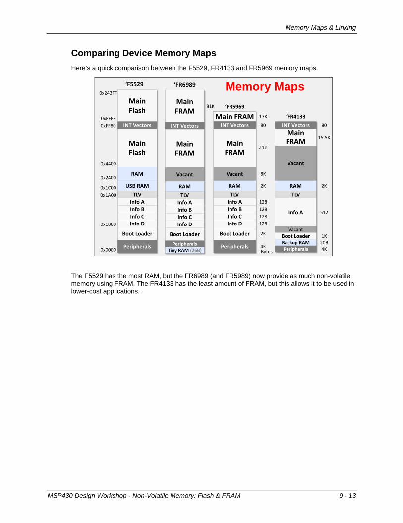
Comparing Device Memory Maps Here’s a quick comparison between the F5529, FR4133 and FR5969 memory maps.
Memory Maps‘F5529
0xFFFF
MainFlash
0xFF80 INT Vectors
0x4400
MainFlash
0x2400RAM
0x1C00 USB RAM0x1A00 TLV
Info AInfo BInfo C
0x1800 Info D
Boot Loader
0x0000 Peripherals
‘FR5969
Main FRAM 17K
INT Vectors 80
MainFRAM
47K
Vacant 8K
RAM 2K
TLVInfo A 128Info B 128Info C 128Info D 128
Boot Loader 2K
Peripherals 4KBytes
0x243FF
‘FR4133INT Vectors 80
MainFRAM 15.5K
Vacant
RAM 2K
TLV
Info A 512
VacantBoot Loader 1KBackup RAM 20BPeripherals 4K
‘FR6989
MainFRAM
81K
INT Vectors
MainFRAM
Vacant
RAMTLV
Info AInfo BInfo CInfo D
Boot Loader
PeripheralsTiny RAM (26B)
The F5529 has the most RAM, but the FR6989 (and FR5989) now provide as much non-volatile memory using FRAM. The FR4133 has the least amount of FRAM, but this allows it to be used in lower-cost applications.
MSP430 Design Workshop - Non-Volatile Memory: Flash & FRAM 9 - 13
Memory Maps & Linking
Sections From a high-level we’ve already learned that there are different types of memory – for example, non-volatile (ROM-like) and volatile (RAM-like) memories.
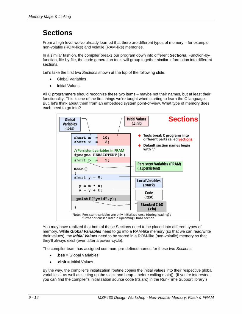
In a similar fashion, the compiler breaks our program down into different Sections. Function-by-function, file-by-file, the code generation tools will group together similar information into different sections.
Let’s take the first two Sections shown at the top of the following slide: • Global Variables
• Initial Values
All C programmers should recognize these two items – maybe not their names, but at least their functionality. This is one of the first things we’re taught when starting to learn the C language. But, let’s think about them from an embedded system point-of-view. What type of memory does each need to go into?
short m = 10;short x = 2;
//Persistent variables in FRAM #pragma PERSISTENT( b )short b = 5;
main(){short y = 0;
y = m * x;y = y + b;
printf("y=%d",y);
}
Sections
Tools break C programs into different parts called Sections
Default section names begin with “.”
Global Variables
(.bss)
Initial Values(.cinit)
Local Variables(.stack)
Code(.text)
Standard C I/O(.cio)
Persistent Variables (FRAM)(.TI.persistent)
bote: Persistent variables are only initialized once (during loading) ;further discussed later in upcoming FRAa section
You may have realized that both of these Sections need to be placed into different types of memory. While Global Variables need to go into a RAM-like memory (so that we can read/write their values), the Initial Values need to be stored in a ROM-like (non-volatile) memory so that they’ll always exist (even after a power-cycle).
The compiler team has assigned common, pre-defined names for these two Sections: • .bss = Global Variables
• .cinit = Initial Values
By the way, the compiler’s initialization routine copies the initial values into their respective global variables – as well as setting up the stack and heap – before calling main(). (If you’re interested, you can find the compiler’s initialization source code (rts.src) in the Run-Time Support library.)
9 - 14 MSP430 Design Workshop - Non-Volatile Memory: Flash & FRAM
Memory Maps & Linking
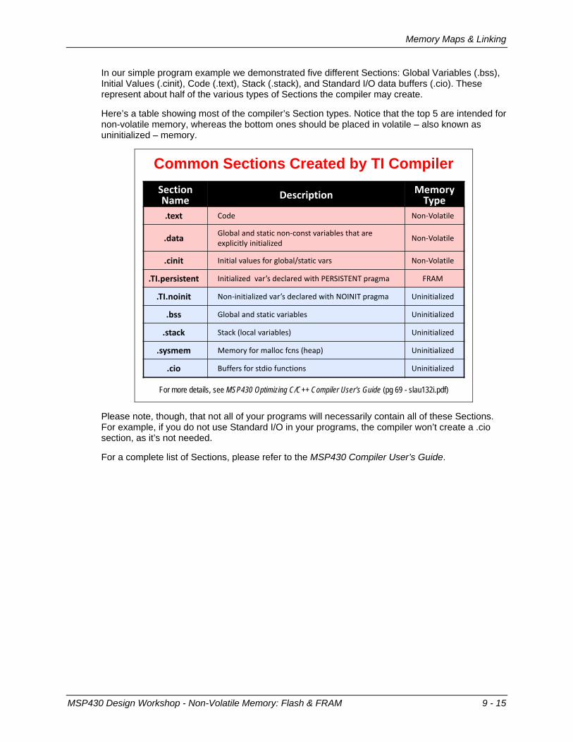
In our simple program example we demonstrated five different Sections: Global Variables (.bss), Initial Values (.cinit), Code (.text), Stack (.stack), and Standard I/O data buffers (.cio). These represent about half of the various types of Sections the compiler may create.
Here’s a table showing most of the compiler’s Section types. Notice that the top 5 are intended for non-volatile memory, whereas the bottom ones should be placed in volatile – also known as uninitialized – memory.
Common Sections Created by TI CompilerSection Name Description Memory
Type.text Code bon-Volatile
.data Global and static non-const variables that are explicitly initialized bon-Volatile
.cinit Initial values for global/static vars bon-Volatile
.TI.persistent Initialized var’s declared with PERSISTEbT pragma FRAa
.TI.noinit bon-initialized var’s declared with bOIbIT pragma Uninitialized
.bss Global and static variables Uninitialized
.stack Stack (local variables) Uninitialized
.sysmem aemory for malloc fcns (heap) Uninitialized
.cio Buffers for stdio functions Uninitialized
For more details, see MSP430 Optimizing C/C++ Compiler User’s Guide (pg 69 - slau132i.pdf)
Please note, though, that not all of your programs will necessarily contain all of these Sections. For example, if you do not use Standard I/O in your programs, the compiler won’t create a .cio section, as it’s not needed.
For a complete list of Sections, please refer to the MSP430 Compiler User’s Guide.
MSP430 Design Workshop - Non-Volatile Memory: Flash & FRAM 9 - 15

Memory Maps & Linking
Linking Linking is the process of bringing together all of your programs object files and assigning addresses to everything that requires memory.
Linking Your Program
Linker.obj
.obj
.lib
.map
-m
.out-o
LinkerCommand
File
Looking at the CMD file...
The inputs to the Linker include the object files created from each of your program source files – whether you wrote the code in C, assembly, or any other language. The object files also include any binary object libraries that you’ve specified in your code.
Note: By default, the compiler always includes the Run-Time Support (RTS) library since it provides the compiler’s initialization routine, along with a variety of other common support functions – such as standard I/O, math, trig, etc.
From these object files the Linker will create an executable binary file (.out). It also creates a Map (.map) file that provides you with a report describing what Sections it found, where it put those Sections, and where every global variable was allocated in memory.
Linker Command File The other “optional” input to the Linker is the Linker Command File (.cmd). We say “optional” because, in reality, it is not optional. Sure, the linker has default settings that will allow it to build a binary file without any user direction – but these defaults rarely work for real-world systems. Realistically, you must use a linker command file.
We show a simple example of a linker command file on the next page…
9 - 16 MSP430 Design Workshop - Non-Volatile Memory: Flash & FRAM

Memory Maps & Linking
Every linker command file is composed of three parts:
1. Input files and linker options: This is not shown below since it is rarely used when the code-generation tools are called from an IDE (like CCS).
2. MEMORY: This part of the .cmd file tells the Linker what memory it can allocate.
3. SECTIONS: This part lets us tell the compiler how – and where – we want each of our Sections to be allocated.
MEMORY{ RAM: origin = 0x2400, length = 0x2000
INFOA: origin = 0x1980, length = 0x0080INFOB: origin = 0x1900, length = 0x0080INFOC: origin = 0x1880, length = 0x0080INFOD: origin = 0x1800, length = 0x0080FLASH: origin = 0x4400, length = 0xBB80FLASH2: origin = 0x10000,length = 0x14400
}SECTIONS{
.bss : {} > RAM
.data : {} > RAM
.sysmem : {} > RAM
.stack : {} > RAM
.text : {}>> FLASH2 | FLASH
.text:_isr : {} > FLASH
.cinit : {} > FLASH | FLASH2
.const : {} > FLASH | FLASH2
.cio : {} > RAM}
Simple Linker Command File
Operators:{ file.obj } specifies files to include in output section
>> indicates output section can be split (if necessary)
| used as ‘or’ symbol; allows list of memory segments as targets for output section
As you can see, each line in MEMORY{} defines a memory segment’s location and size. It is common to find each of the different areas of our memory-map described here. The MEMORY specifications can be broken up or combined as needed for your system, though this isn’t very common.
In the SECTIONS{} portion of the .cmd file we see each of our Sections being directed into the appropriate memory segment. In many systems, it’s really as simple as shown above. Of course, there are more complicated systems that require a “finer” control of memory placement. To this end, the Linker is incredibly flexible.
Unfortunately, digging into all the Linker’s details is outside the scope of this workshop. We’ll see an advanced example later in this chapter, but we refer you to the MSP430 Assembly Language Tools User’s Guide (slau131j.pdf) for all the gory details.
Hint: The MSP430 team has created a default linker command file for each specific MSP430 device. This is very handy! In fact, you may never have to create (or even modify) a linker command file. Even if you have to do so, their default file provides you a great starting point. This is surely better than the days where everyone had to create their own from scratch.
MSP430 Design Workshop - Non-Volatile Memory: Flash & FRAM 9 - 17
Memory Maps & Linking
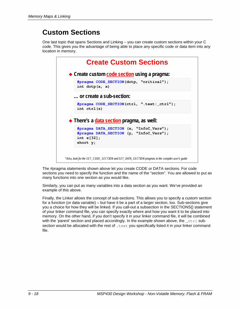
Custom Sections One last topic that spans Sections and Linking – you can create custom sections within your C code. This gives you the advantage of being able to place any specific code or data item into any location in memory.
Create Custom Sections Create custom code section using a pragma:
… or create a sub-section:
There’s a data section pragma, as well:
#pragma CODE_SECTION(dotp, “critical”);int dotp(a, x)
#pragma CODE_SECTION(ctrl, “.text:_ctrl”);int ctrl(z)
#pragma DATA_SECTION (x, “InfoC_Vars”);#pragma DATA_SECTION (y, “InfoC_Vars”);int x[32];short y;
* Also, look for the SET_CODE_SECTION and SET_DATA_SECTION pragmas in the compiler user’s guide
The #pragma statements shown above let you create CODE or DATA sections. For code sections you need to specify the function and the name of the “section”. You are allowed to put as many functions into one section as you would like.
Similarly, you can put as many variables into a data section as you want. We’ve provided an example of this above.
Finally, the Linker allows the concept of sub-sections. This allows you to specify a custom section for a function (or data variable) – but have it be a part of a larger section, too. Sub-sections give you a choice for how they will be linked. If you call-out a subsection in the SECTIONS{} statement of your linker command file, you can specify exactly where and how you want it to be placed into memory. On the other hand, if you don’t specify it in your linker command file, it will be combined with the ‘parent’ section and placed accordingly. In the example shown above, the _ctrl sub-section would be allocated with the rest of .text you specifically listed it in your linker command file.
9 - 18 MSP430 Design Workshop - Non-Volatile Memory: Flash & FRAM

Memory Maps & Linking
In the example linker command file below, we didn’t specify the _ctrl sub-section, so it will end up being allocated with the rest of .text. Alternatively, notice that another sub-section (.text:_isr) was specifically called out and will be linked independently from the rest of .text.
MEMORY{ RAM: origin = 0x2400, length = 0x2000
INFOA: origin = 0x1980, length = 0x0080INFOB: origin = 0x1900, length = 0x0080INFOC: origin = 0x1880, length = 0x0080INFOD: origin = 0x1800, length = 0x0080FLASH: origin = 0x4400, length = 0xBB80FLASH2: origin = 0x10000,length = 0x14400
}SECTIONS{ critcal : {} > 0x2400
.bss : {} > RAM
.data : {} > RAM
.sysmem : {} > RAM
.stack : {} > RAMInfoC_Vars : {} > INFOC type=NOINIT
.text : {}>> FLASH2 | FLASH
.text:_isr : {} > FLASH
.cinit : {} > FLASH | FLASH2
.const : {} > FLASH | FLASH2
.cio : {} > RAM }
CMD File with Custom Sections Custom sections allow
you to place code: At specific locations In a specific order
NhINIT type tells system init code to ignore initialization for that output section
Sub-sections allow you to specify the sub-sect’s location… or, if not specified, it’s linked along with the parent section (ie “.text”)
This is a contrived example to show the mechanism; we’ll see ‘real’ examples later in the chapter
Note: Let us caution you, though, that you should use this judiciously. We recommend that you use Custom Sections (and/or customize the linker command file) only when “something” has to go in a very specific location. In fact, though, we will show you an example of this later in this chapter.
Side Bar
Sidebar – Using the “wrong” type of memory As stated earlier, even though this goes against common style, you can place:
• “Code into RAM”
• “Variables into Flash”
While this is not a problem for the linker (because it only assigns addresses), it is tricky from a hardware point-of-view. Making these options work correctly requires extra code.
For example, before you run code from internal RAM, must first copy it from its non-volatile memory location into the RAM. This could be done with either the CPU or the DMA.
Updating variables stored in Flash requires a series of steps – as does any programming of Flash memory. We provide an example of this in the upcoming lab exercises.
MSP430 Design Workshop - Non-Volatile Memory: Flash & FRAM 9 - 19

Using Flash
Using Flash The Flash Memory Controller provides access to the Flash non-volatile memory. Read accesses occur normally, just as you might read from a RAM memory. Writes, on the other hand, require a correct procedure to be followed. Writing directly to Flash causes an interrupt (if enabled) … and doesn’t modify the Flash memory.
Flash Memory Controller Writing directly to Flash
causes an interrupt Must use ‘password’ when
writing to Flash control registers – or a PUC occurs
Writing to memory requires ‘procedure’
1. Enable write2. Write data3. Disable write
DriverLib FLASH API makes Flash easy-to-use
Must erase before write Must erase entire segment You can write 8-, 16-, or 32-bits Must Unlock InfoA before
writing to it (to avoid INT)
The Flash write procedure includes: • Disable the Watchdog Timer, if it is running.
• Clear the Flash LOCK bit (using the appropriate Flash Control Register password)
• Enable Flash write mode by setting WRT=1 (again, using the correct password)
• Writing to the memory as needed – checking the BUSY bit to make sure each write is complete before starting another write.
• Disable write mode and re-LOCK the Flash (yet again, using the correct register password).
Note: Due to the complexity of these write operations, we recommend that you utilize the FLASH DriverLib API, which will be discussed shortly.
9 - 20 MSP430 Design Workshop - Non-Volatile Memory: Flash & FRAM
Using Flash
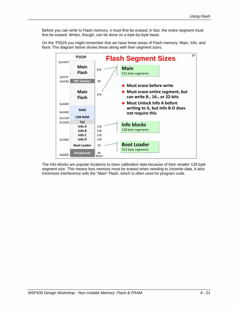
Before you can write to Flash memory, it must first be erased; in fact, the entire segment must first be erased. Writes, though, can be done on a byte-by-byte basis.
On the ‘F5529 you might remember that we have three areas of Flash memory: Main, Info, and Boot. The diagram below shows these along with their segment sizes.
Flash Segment Sizes‘F5529
0xFFFF
MainFlash
81K
0xFF80 INT Vectors 80
0x4400
MainFlash
47K
0x2400RAM
0x1C00 USB RAM0x1A00 TLV
Info A 128Info B 128Info C 128
0x1800 Info D 128
Boot Loader 2K
0x0000 Peripherals 4KBytes
0x243FF
Info blocks128 byte segments
Boot Loader512 byte segments
Main512 byte segments
Must erase before write Must erase entire segment, but
can write 8-, 16-, or 32-bits Must Unlock Info A before
writing to it, but Info B-D does not require this
The Info blocks are popular locations to store calibration data because of their smaller 128 byte segment size. This means less memory must be erased when needing to (re)write data. It also minimizes interference with the “Main” Flash, which is often used for program code.
MSP430 Design Workshop - Non-Volatile Memory: Flash & FRAM 9 - 21

Using Flash
Using DriverLib to Write to Flash Notice the functions found in DriverLib’s FLASH module – these let you erase, write, fill and check the status of the MSP430’s Flash memory.
FLASH API Writing to memory requires
‘procedure’1. Enable write2. Write data3. Disable write
Writing directly to Flash causes an interrupt
Must use ‘password’ when writing to Flash control registers – or a PUC occurs
DriverLib FLASH API makes Flash easy-to-use
Must erase before write Must erase entire segment You can write 8-, 16-, or 32-bits Must Unlock InfoA before
writing to it (to avoid INT)
Flash erase operations are managed by: FlashCtl_segmentErase() FlashCtl_eraseCheck() FlashCtl_bankErase()
Flash writes are managed by: FlashCtl_write8() FlashCtl_write16() FlashCtl_write32() FlashCtl_memoryFill32()
Status is given by: FlashCtl_status() FlashCtl_eraseCheck()
Segment InfoA memory lock/unlock: FlashCtl_lockInfoA() FlashCtl_unlockInfoA()
The following code example uses DriverLib to perform a block erase on Info A; then write an array of data to it. Remember, Info A has an extra “lock” feature that you need to unlock beforehand, then should re-lock afterwards (this is not required for the other Info segments).
Code Example: Writing to “Info A”#pragma DATA_SECTION (calibration_data_char, “.infoA”)uint8_t calibration_data_char[16] = { 0x00,0x01,0x02,...};uint16_t status;
// Unlock Info Segment AFlashCtl_unlockInfoA();
do { // Erase INFOAFlashCtl_segmentErase( (uint8_t*)INFOA_START );status = FlashCtl_eraseCheck((uint8_t*)INFOA_START,128);
} while ( status == STATUS_FAIL );
// Write calibration data to INFOAFlashCtl_write8( calibration_data_char,
(uint8_t*)INFOA_START, 16 );
// Lock Info Segment AFlashCtl_lockInfoA();
9 - 22 MSP430 Design Workshop - Non-Volatile Memory: Flash & FRAM
Using FRAM (and the MPU)
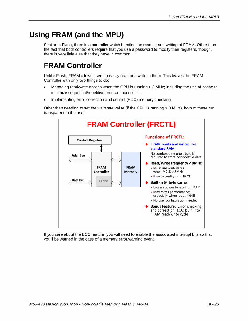
Using FRAM (and the MPU) Similar to Flash, there is a controller which handles the reading and writing of FRAM. Other than the fact that both controllers require that you use a password to modify their registers, though, there is very little else that they have in common.
FRAM Controller Unlike Flash, FRAM allows users to easily read and write to them. This leaves the FRAM Controller with only two things to do: • Managing read/write access when the CPU is running > 8 MHz; including the use of cache to
minimize sequential/repetitive program accesses.
• Implementing error correction and control (ECC) memory checking.
Other than needing to set the waitstate value (if the CPU is running > 8 MHz), both of these run transparent to the user.
FRAM Controller (FRCTL)Functions of FRCTL: FRAM reads and writes like
standard RAMbo cumbersome procedure isrequired to store non-volatile data
Read/Write frequency < 8MHz aust use wait-states
when aCLK > 8aHz Easy to configure in FRCTL
Built-in 64 byte cache Lowers power by exe from RAa aaximizes performance;
especially when loops < 64B bo user configuration needed
Bonus Feature: Error checking and correction (ECC) built into FRAa read/write cycle
Control Registers
FRAMController
FRAMMemory
Addr Bus
Data Bus Cache
If you care about the ECC feature, you will need to enable the associated interrupt bits so that you’ll be warned in the case of a memory error/warning event.
MSP430 Design Workshop - Non-Volatile Memory: Flash & FRAM 9 - 23

Using FRAM (and the MPU)
Unified Memory FRAM supports unified memory – which means that you can store both Code and Data in FRAM.
Unified Memory : Code and DataFRAM
ProgramCode
Data(constants)
Data(variables)
FRAM Advantages: Mix & Match FRAM
for code and/or data Easy to read & write Fast High Endurance Non-volatile Very low power
If FRAM writes as easy as RAM,what could happen in your system?
It’s often common to see the FRAM contain program code, constant data (i.e. read-only data), as well as read/write (random access) data.
Can you think of what might go wrong, though, when using FRAM in this way?
_________________________________________________________________________
_________________________________________________________________________
Actually, it’s not a problem with the multi-use of FRAM; it’s more a problem with how easy it is to write to FRAM…
9 - 24 MSP430 Design Workshop - Non-Volatile Memory: Flash & FRAM

Using FRAM (and the MPU)
What Could Happen to FRAM? The problem, as we said, is that FRAM is so easy to write to – unlike Flash. While generally this is a good thing, what happens if your program goes rogue? For example, what happens if an error causes your program stack to overrun its “boundary”?
Unified Memory : What Could Happen?FRAM
ProgramCode
Data(constants)
Data(variables)
FRAM Advantages: Mix & Match FRAM
for code and/or data Easy to read & write Fast High Endurance Non-volatile Very low power
Potential ERROR: What if your program
code accidentally wrote over itself?
What if the stack overflows?
MPU to the rescue...
When using Flash, this problem would usually cause a system reset (PUC) since you cannot write directly to it without using the proper procedure. With FRAM, though, there isn’t a technological restriction to these types of programmatic errors.
The solution chosen by TI was to include a Memory Protection Unit (MPU) in these devices.
MSP430 Design Workshop - Non-Volatile Memory: Flash & FRAM 9 - 25

Using FRAM (and the MPU)
Memory Protection Unit (MPU) The MPU allows you to divide your FRAM into 2 or 3 segments and then individually apply access permissions to each of these segments. As shown below, our FRAM was broken into 3 segments with: one segment (our code) set to only allow code Execution; another segment only allows Read access; while the last allows read or write accesses.
Unified Memory : What Could Happen?FRAM
ProgramCode
Data(constants)
Data(variables)
Memory Protection Unit:
MPU Let’s you partitionFRAM into three segments
1. Execute only
2. Read Only
3. Read / Write
FRAM Advantages: Mix & Match FRAM
for code and/or data Easy to read & write Fast High Endurance Non-volatile Very low power
Potential ERROR: What if your program
code accidentally wrote over itself?
What if the stack overflows?
How does the MPU work?
With the MPU configured and enabled in this manner, a write access to the “code” segment generates an exception. This exception either causes a reset (PUC) or a non-maskable interrupt (NMI) depending upon how you’ve configured the MPU.
In this way, you’re protected from potential errors due to errant writes to FRAM.
9 - 26 MSP430 Design Workshop - Non-Volatile Memory: Flash & FRAM

Using FRAM (and the MPU)
Using the Memory Protection Unit (MPU) Looking at the MPU more closely, we see that two registers define the boundaries for the three segments. Writing addresses to these registers defines each segment’s location and size. An upcoming example will show how we can use linker symbols to set these boundaries appropriately.
Control Registers
MPUFRAM
Memory
Addr
Data Bus
Interrupts
Memory Protection UnitFRAM
ProgramCode
Data(constants)
Data(variables)
MPUSEDB1
MPUSEDB2
Memory Protection Unit:
MPU Let’s you partitionFRAM into three segments
1. Execute only
2. Read Only
3. Read / Write
After a PUC reset, the MPU registers are set to their default state. This causes the FRAM to be configured as a single segment with all access permissions enabled (Read, Write and Execute).
Notice – Use the MPU!
* Cited from the Application Note:MSt430™ FR!M Technology – How To and Best tractices (SLAA628)
NOTE: Ht is very importMnt to MlRMys MppropriMtely configure Mnd enMNlethe MPU Nefore Mny softRMre deployment or production code releMse to ensure mMximum MpplicMtion roNustness Mnd dMtM integrityB The MPU should Ne enMNled Ms eMrly Ms possiNle Mfter the device stMrts executing code coming from M poRer-on or reset Mt the Neginning of the F stMrtup routine even Nefore the mMin()routine is enteredB
MSP430 Design Workshop - Non-Volatile Memory: Flash & FRAM 9 - 27

Using FRAM (and the MPU)
As we might expect, looking at the following diagram we see that the MPU watches addresses flowing into the FRAM controller. This allows it to intercept non-approved memory accesses to FRAM.
Memory Protection Unit (MPU)
Control Registers
MPU
FRAMController
FRAMMemory
Addr
Data Bus
Interrupts
Cache
No procedure to write to FRAM Configure MPU for 1-3 sections
(1 by default) to protect program and/or data (on 1KB boundaries*)
Violating protection causes PUC or interrupt
Must use ‘password’ when writing to control registers – or else a PUC occurs
DriverLib FRAM and MPU API’s makes it easy-to-use
Configure wait-states if CPU is running > 8MHz
To use MPU1. Set segment border registers2. Turn on MPU3. (Optional) Lock MPU registers
How do we configure the MPU?
Using the MPU requires: • Writing a password to the MPU registers
• Setting the address segment boundary registers
• Setting the Read/Write/Execute permissions for each segment
• Configuring the violation response – should a PUC or NMI be generated whenever a segment is incorrectly accessed
• Turn on the MPU
• Finally, you may wish to Lock the MPU to prevent any changes (until the next BOR reset)
While the procedure here might appear as long as the Flash writing procedure, remember that you only need to do this once … not every time you want to write to FRAM.
A couple of additional notes about the MPU: − Each segment can be configured individually for access permissions.
− You can also set access permissions for the Info blocks (as a whole).
− You can continue to change the MPU settings even after the MPU is enabled … that is, unless you lock the MPU registers, in which case a reset is required before you can access the MPU registers again.
9 - 28 MSP430 Design Workshop - Non-Volatile Memory: Flash & FRAM

Using FRAM (and the MPU)
What are the Interrupt Options?
What Happens if MPU is Incorrectly Accessed?
A better way might be...
If a Memory Segment is accessed incorrectly
NMI
PUC
IFG bit
If an access violation occurs the IFG bit is always set “Assert PUC” lets you choose whether to have a
PUC or NMI generated Enable NMI can turn “off” NMI If PUC is off and NMI is off, only IFG is set (no interrupt)
MSP430 Design Workshop - Non-Volatile Memory: Flash & FRAM 9 - 29

Using FRAM (and the MPU)
MPU Graphical User Interface Starting with CCSv6, the MSP430 team has created a convenient GUI to simplify the process of setting up the MPU. The following screen capture shows the simple text/check boxes required to set it up.
MPU Settings via GUI (CCSv6)
A better way might be...
Intuitive way to set segment addresses and assign permissions
Allows selection of interrupts and/or PUC on violation
Lock configuration until BhR event
In fact, you can even elect to the let the GUI handle setting the boundary registers for you.
MPU Settings via GUI (CCSv6 only)
Intuitive way to set segment addresses and assign permissions
Allows selection of interrupts and/or PUC on violation
Lock configuration until BhR event
You can let thecode generation tools manage the MPU automatically(explained next)
How does this "auto" setting work?
9 - 30 MSP430 Design Workshop - Non-Volatile Memory: Flash & FRAM

Using FRAM (and the MPU)
The key to automating the GUI is found in the Linker Command File (CMD). The following fancy linker syntax – found in the default linker CMD file – groups the non-volatile read/write sections created by the linker.
The GUI tool creates 2 MPU segments: • Segment 1 contains the Read/Write input sections that require non-volatile storage … or, in
the case of .cio, are large enough that they are often stored in “Main” FRAM space
• Segment 2 is not created as the starting address of Read/Execute non-volatile memory is assigned to both MPU Segment Border registers.
• Segment 3 contains the input sections for Read-Only and Execute:
− Read Only sections such as the initial values for variables
− Finally, the Executable sections (.i.e. .text) which contain the code
Linker CMD file is Key to GUI “auto” Setting
Default CMD creates 2 groups allocated to FRAM:u Read/Write Read hnly + Execute
Defines address symbol“fram_rx_start” which is at end of read/write (i.e. start of “rx”)
DUI creates 2 segments (1 & 3) by assigning the same symbol toMPUSEDB2 and MPUSEDB1.
u
Along with creating these output sections (and linking them into FRAM), the linker syntax above also creates a symbol which defines the end of the Read/Write group and the start of each the Read/Execute output sections.:
• fram_rx_start
The MPU GUI uses this symbol, but you can also access it from your code by using the proper external declaration in your C file. An example of this is coming up later in this chapter.
MSP430 Design Workshop - Non-Volatile Memory: Flash & FRAM 9 - 31

Using FRAM (and the MPU)
FRAM Code Example The FRAM and MPU DriverLib functions can be used to configure FRAM access. We’ll examine a few of these functions in our code example on the next page.
DriverLib FRAM & MPU API’sFRAM writes can be managed by: FRAMCtl_write8() FRAMCtl_write16() FRAMCtl_write32() FRAMCtl_memoryFill32()
FRAM interrupts are handled by: FRAMCtl_enableInterrupt() FRAMCtl_getInterruptStatus() FRAMCtl_disableInterrupt()
Status is given by: FRAMCtl_configureWaitStateControl() FRAMCtl_delayPowerUpFromLPM()
Note: Setting the MPU with DriverLib is an alternative to using the GUI tool. If you’re not using CCSv6, yet, then this is absolutely your best option. But this is also a good solution for those of you who prefer to use code versus using a GUI.
9 - 32 MSP430 Design Workshop - Non-Volatile Memory: Flash & FRAM

Using FRAM (and the MPU)
Configuring the MPU using DriverLib The following example uses the symbols created by the linker to configure the boundaries between the MPU’s three segments. The MPU_initTwoSegments() function makes it easy to configure the segment boundaries and set the access permissions.
After configuring the segments, we tell the MPU we don’t want to generate a PUC when a violation in Segment 1 occurs – instead, we’ll get an NMI if a violation occurs in this segment.
Finally, we start the MPU running.
Configuring MPU in Software
extern const uint16_t fram_rx_start;
void initMPU(void) {
// Configure MPU as two SegmentsMPU_initTwoSegments( MPU_BASE,(uint16_t) &fram_rx_start >> 4, // Bound between 1 & 3MPU_READ | MPU_WRITE | MPU_EXEC, // Seg 1: all access MPU_READ | MPU_EXEC ); // Seg 3: read & exe
// Disable PUC on segment access violation for segment 1MPU_disablePUCOnViolation( MPU_BASE,
MPU_FIRST_SEG );
// Enable PUC on segment access violation for segment 3MPU_enablePUCOnViolation( MPU_BASE,
MPU_THIRD_SEG );
// Start MPU protectionMPU_start( MPU_BASE );
For CCSv5.5 users or if you want to setup the MPU using C code:
MSP430 Design Workshop - Non-Volatile Memory: Flash & FRAM 9 - 33
Using FRAM (and the MPU)
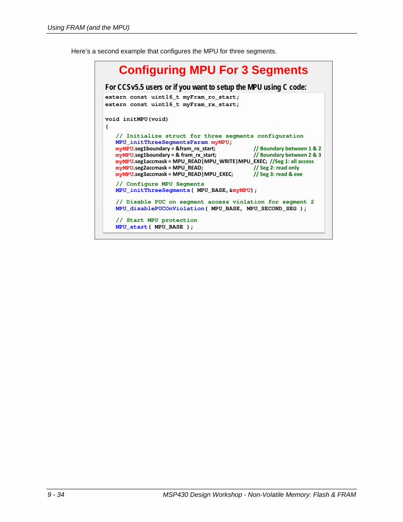
Here’s a second example that configures the MPU for three segments.
Configuring MPU For 3 Segments
extern const uint16_t myFram_ro_start;extern const uint16_t myFram_rx_start;
void initMPU(void) {
// Initialize struct for three segments configurationMPU_initThreeSegmentsParam myMPU;myMPU.seg1boundary = &fram_ro_start; // Boundary between 1 & 2myMPU.seg1boundary = & fram_rx_start; // Boundary between 2 & 3myMPU.seg1accmask = MPU_READ|MPU_WRITE|MPU_EXEC; //Seg 1: all accessmyMPU.seg2accmask = MPU_READ; // Seg 2: read onlymyMPU.seg3accmask = MPU_READ|MPU_EXEC; // Seg 3: read & exe
// Configure MPU SegmentsMPU_initThreeSegments( MPU_BASE,&myMPU);
// Disable PUC on segment access violation for segment 2MPU_disablePUCOnViolation( MPU_BASE, MPU_SECOND_SEG );
// Start MPU protectionMPU_start( MPU_BASE );
For CCSv5.5 users or if you want to setup the MPU using C code:
9 - 34 MSP430 Design Workshop - Non-Volatile Memory: Flash & FRAM

Using FRAM (and the MPU)
Putting Variables into FRAM A unique advantage to placing variables in FRAM – besides the extra storage space it provides – is that it allows variables to be non-volatile. That is, their value is retained – even upon power loss.
An easy way to direct a variable to FRAM is to make it “persist”; that is, we can use a compiler pragma to indicate that the variable’s value should persist even when power is removed from the device.
Creating a Persistent Variable#pragma PERSISTENT( b )uint16_t b = 3;
int MyLine( int m, int x ){
int y;
y = (m * x) + b;Return ( y );
}
FRAM makes this easy – as simple to use as RAM Declaring variable as persistent means it’s:
Placed into “.TI.persistent” section which is allocated to FRAM by default linker command file
Initialized only once, when the program is loaded into FRAM and therefore retains its value whenever the program is reset/restarted
NOINIT pragma similar to PERSISTENT, but uses “.TI.noinit”, places the section in RAM, and never initializes the variable
MSP430 Design Workshop - Non-Volatile Memory: Flash & FRAM 9 - 35
Using FRAM (and the MPU)
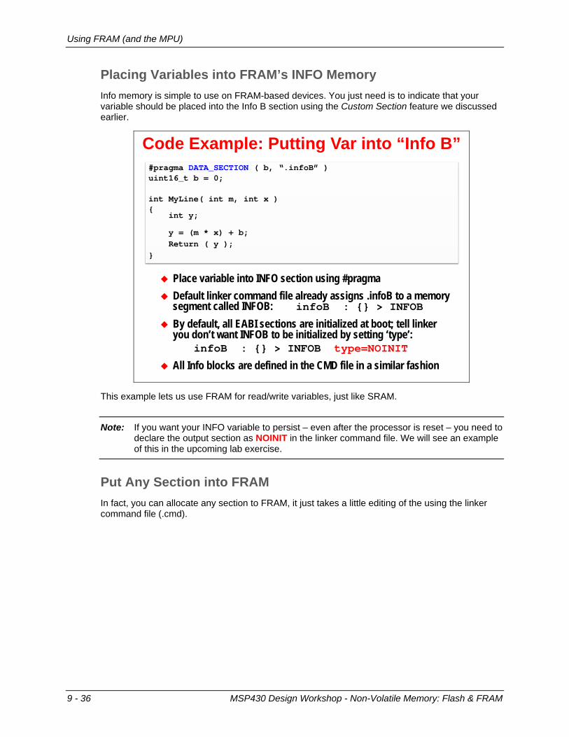
Placing Variables into FRAM’s INFO Memory Info memory is simple to use on FRAM-based devices. You just need is to indicate that your variable should be placed into the Info B section using the Custom Section feature we discussed earlier.
Code Example: Putting Var into “Info B”#pragma DATA_SECTION ( b, “.infoB” )uint16_t b = 0;
int MyLine( int m, int x ){
int y;
y = (m * x) + b;Return ( y );
}
Place variable into INFO section using #pragma Default linker command file already assigns .infoB to a memory
segment called INFOB: infoB : {} > INFOB
By default, all EABI sections are initialized at boot; tell linker you don’t want INFOB to be initialized by setting ‘type’:
infoB : {} > INFOB type=NOINIT
All Info blocks are defined in the CMD file in a similar fashion
This example lets us use FRAM for read/write variables, just like SRAM.
Note: If you want your INFO variable to persist – even after the processor is reset – you need to declare the output section as NOINIT in the linker command file. We will see an example of this in the upcoming lab exercise.
Put Any Section into FRAM In fact, you can allocate any section to FRAM, it just takes a little editing of the using the linker command file (.cmd).
9 - 36 MSP430 Design Workshop - Non-Volatile Memory: Flash & FRAM

Using FRAM (and the MPU)
Setting FRAM Waitstates Setting the FRAM’s waitstates involves a simple call to one DriverLib function. Look in the datasheet to find the number of waitstate values you should use for your system.
Setting FRAM Wait-States
// If you run the CPU > 8 MHz, you need to set wait-statesFRAMCtl_configureWaitStateControl( FRAM_ACCESS_TIME_CYCLES_1 );
Hint: Place this in your initClocks() function – near your MCLK setup code
MSP430 Design Workshop - Non-Volatile Memory: Flash & FRAM 9 - 37

Using FRAM (and the MPU)
Notes QQQQQQQQQQQQQQQQQQQQQQQQQQQQQQQQQQQQQQQQQQQQQQQQQQQQQQQQQQQQQQQQQQQQQQQQQQQQQQQQQQQQQQQQQQQQQQQQQQQQQQQQQQQQQQQQQQQQQQQQQQQQQQQQQQQQQQQQQQQQQQQQQQQQQQQQQQQQQQQQQQ QQQQQQQQQQQQQQQQQQQQQQQQQQQQQQQQQQQQQQQQQQQQQQQQQQQQQQQQQQQQQQQQQQQQQQQQQQQQQQQQQQQQQQQQQQQQQQQQQQQQQQQQQQQQQQQQQQQQQQQQQQQQQQQQQQQQQQQQQQQQQQQQQQQQQQQQQQQQQQQQQQ QQQQQQQQQQQQQQQQQQQQQQQQQQQQQQQQQQQQQQQQQQQQQQQQQQQQQQQQQQQQQQQQQQQQQQQQQQQQQQQQQQQQQQQQQQQQQQQQQQQQQQQQQQQQQQQQQQQQQQQQQQQQQQ
9 - 38 MSP430 Design Workshop - Non-Volatile Memory: Flash & FRAM

Memory Protection on the 'FR2xx/4xx
Memory Protection on the 'FR2xx/4xx
FRAMCtl_write16() ExampleFRAM writes can be managed by: FRAMCtl_write8() FRAMCtl_write16() FRAMCtl_write32() FRAMCtl_memoryFill32()
#pragma PERSISTENT( count ) // Direct count into FRAMuint16_t count = 0;uint16_t temp = 0;
temp = 5;
// Write the value of temp back to the 'count' FRAMCtl_write16(
&temp, // 'from' address of data &count, // 'to' address of data1 // How many elements to
);
MSP430 Design Workshop - Non-Volatile Memory: Flash & FRAM 9 - 39

System Init Functions
System Init Functions
Software System Initialization
Initialize System
reset vector
short m = 10;short b = 2;short y = 0;
main(){short x = 0;scanf(x);malloc(y);y = m * x;y = y + b;
}
_main
Reset Vector
_c_int00
1. Initialize compiler’s stack and heap
2. Call the function: _system_pre_init()
3. If return=1 then:Initialize global and static variables
4. Call _main
_system_pre_init()
For more information on “reset events”, please refer to Chapter 4.
Example _system_pre_init()int _system_pre_init(void) {
// Stop watchdog timerWDT_A_hold( WDT_A_BASE );
// Configure and start MPUinitMPU( );
// Returning “1” tells compiler to complete variable// initialization; alternatively, “0” says to skip itreturn(1);
}
Perform “early” system initializations by writing _system_pre_init() function: It’s called by compiler’s boot routine (rts430_eabi.lib) Overload compiler’s function by writing your own Compiler’s default pre-init function is found in the Run-Time Support
library – it’s empty except for return(1);
Returning 1 tells the compiler to initialize global and static variables, while 0 tells it to skip this this step
9 - 40 MSP430 Design Workshop - Non-Volatile Memory: Flash & FRAM

Lab 9 Exercises
Lab 9 Exercises
Lab Exercises Lab A – Count Power Cycles with Non-Volatile Variable
Create a non-volatile variable – use it to count the # of power-cycleso Blink LED the # of times there’s been a power cycleo printf() to console the # of power cycles
Use custom sections and linker command file to create the NVM variable (Flash only) Use API to write to NVM Use memory map and memory browser to ascertain where variables
were allocated by the linker (FRAM) Alternate Lab A – Use PERSISTENT pragma (F5529) Alternate Lab A – Low Wear Flash writes
Explore the provided, albeit simple, low-wear flash write example (FR5969) Lab B – MPU Configuration
Configure MPU to use 2 segments Write to ‘read/execute-only’ segment of FRAM to cause a memory
violation interrupt
* Note: We don’t have a (FR4133) Lab B… but the LCD chapter contains an extension of Lab9a.
MSP430 Design Workshop - Non-Volatile Memory: Flash & FRAM 9 - 41
Lab 9 Exercises
Lab 9a – Using Non-Volatile Variables lab_09a_info_fram (or lab_09a_info_flash) This lab uses non-volatile memory to store a data value so that it will be available after a power-cycle.
The value will be stored in Info memory, which a non-volatile memory (NVM) segment set aside for data information. The 'F5529 uses flash technology to store non-volatile information, while the 'FR5969 & 'FR4133 use FRAM.
The code will keep track of how many power-cycles (BOR's) have occurred. After power up and initializing the GPIO, the code looks for a count value in NVM, it then increments the count value and: • Writes the updated value back to Flash or FRAM
• Prints out the # of power-cycle counts with printf()
• Blinks the LED count # of times
To minimize typing, we created the project for you. The "hello.c" file in this project is an amalgam of labs:
− lab_03a_gpio for the gpio setup
− lab_04b_wdt for the printf functionality
To this we've added: − Logic to manage the "count" value
− For the ‘F5529, we wrote a function which writes to Flash Info B – since it needs to be erased before being written to. (The FRAM devices don’t need this step!)
− You will need to fill in a few answers from your Lab 9a worksheet
There is no MPU "protection" setup for the 'FR5969 FRAM in this exercise. That is shown in lab_09b_mpu_gui or lab_09b_mpu_with_driverlib. (Note that the F5529 and FR4133 devices don't have an MPU.)
9 - 42 MSP430 Design Workshop - Non-Volatile Memory: Flash & FRAM

Lab 9 Exercises
Worksheet
1. Examine the linker command file (.cmd) and find the name of the memory area that represents the Info memory. (You only need to complete the table for your processor.)
Processor Memory Section Name Address
F5529 INFOB
FR5969 INFOB
FR4133 INFOA
Finish this line of code:
#pragma __________________ (count, "____________")
static uint16_t count;
2. Again, looking at the linker command file, what address symbol is created by the linker to represent the starting address of executable code?
_________________________________________________________________________
3. (‘F5529 only) What functions are needed to erase and write to Flash?
(Note: We’re interested in writing 16-bit integers to Flash.)
//Erase INFOB do {
________________________( (uint8_t*)INFOB_START ); status = FlashCtl_eraseCheck( (uint8_t*)INFOB_START, NUMBER_OF_BYTES ); } while (status == STATUS_FAIL); //Flash Write
__________________________________(
(uint16_t*) value, (uint16_t*) flashLocation, 1 );
F5529
MSP430 Design Workshop - Non-Volatile Memory: Flash & FRAM 9 - 43
Lab 9 Exercises
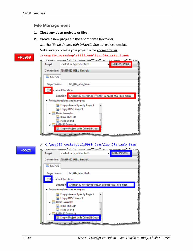
File Management 1. Close any open projects or files.
2. Create a new project in the appropriate lab folder.
Use the “Empty Project with DriverLib Source” project template.
Make sure you create your project in the correct folder: C:\msp430_workshop\F5529_usb\lab_09a_info_flash
or C:\msp430_workshop\fr5969_fram\lab_09a_info_fram
FR5969
F5529
9 - 44 MSP430 Design Workshop - Non-Volatile Memory: Flash & FRAM

Lab 9 Exercises
or C:\msp430_workshop\fr4133_fram\lab_09a_info_fram
3. Delete main.c from the project.
This isn’t needed since we’ve provided the file hello.c file which contains main().
4. Verify that your project contains the file hello.c.
It should look like:
or
or
If this file is missing, then you probably created the project in the wrong directory. You can
either add this file to your project (from the directory shown in Step 1) or delete the project and start over again.
FR4133
MSP430 Design Workshop - Non-Volatile Memory: Flash & FRAM 9 - 45

Lab 9 Exercises
Edit Code 5. Fill in the blanks in the hello.c file.
Use your answers from the worksheet questions (page 9-43).
6. Increase the heap size to 320.
This was a change we performed back in Lab 2 in order to get C Standard I/O to work. Here’s a quick reminder:
Right-click on Project → Properties…
Build → MSP430 Linker → Basic Options → Heap Size
7. ('FR5969 only) Modify the .infoB setting in linker command file.
Since FRAM reads/writes like SRAM, the compiler auto-initializes it each time our C program starts … just like any other global variable. Of course, that’s not what we want in this instance – we want to use the non-volatile nature of FRAM to maintain the value of ‘count’ when the power is off. To make this happen, we can tell the tools to “not initialize” the variables. This can be done by editing one line in the linker command file to add the NOINIT type.
.infoB : {} > INFOB type=NOINIT
We could have limited the scope of our NOINIT modification, but it’s an easier edit to set this type for the entire .infoB section.
Note: This step isn’t needed on the ‘FR4133 device – even though it’s also FRAM based. While the ‘FR5969 has a more advanced MPU, it’s not turned on by default. Conversely, the ‘FR4133 has a simple memory protection mechanism, but it is enabled by default.
FR5969
9 - 46 MSP430 Design Workshop - Non-Volatile Memory: Flash & FRAM

Lab 9 Exercises
Build and Evaluate 8. Build program the program.
Fix any syntax errors and rebuild until your program compiles successfully.
9. Open the .map file (from your project’s Debug folder) and answer the questions below. The .map file is a report created by the linker which records where memory was allocated.
(We used INFOA for the FR4133 and INFOB for FR5969 and F5529).
‘F5529 ‘FR5969 ‘FR4133
Which INFO Section was used? INFOB INFOB INFOA
Address of INFOA or INFOB
Where was this INFOA/INFOB address specified to the tools?
Address of .infoA or .infoB
Compiler’s Boot Routine: _c_int00 (.text:isr)
Main Code (.text)
Length of code* (.text)
Address of count
fram_rx_start
*Note that turning on the optimizer may allow the compiler to build a smaller program. Also, you would not want to use printf() in a production level program as this leads to very inefficient programs.
10. Why does the code (.text) section start so far away from the beginning of Main Flash or FRAM? (Hint: Look at the section allocations in the .cmd file.)
_________________________________________________________________________
_________________________________________________________________________
MSP430 Design Workshop - Non-Volatile Memory: Flash & FRAM 9 - 47

Lab 9 Exercises
Run the Program to Watch the Non-Volatile Variable 11. Launch the debugger.
12. Open the Memory Browser window.
View → Memory Browser
Try looking at some of the locations used in our code:
0x1900 (or 0x1800) &fram_rx_start (for ‘FR5969 devices) &count
From the Memory Browser, what is the address of: &count _________________________
13. To watch their values, add variables to the Expressions Window for:
count c (for ‘F5529 devices) i (you can also see ‘i’ in the local Variables window)
Hint: You may want to change the number format for “c” to “hex”: Right-click expression → Number Format → Hex
14. Single-Step through the code to watch it work.
The Memory Browser is interesting because you can see the variable in Flash (or FRAM).
Hint: You can also modify the value in Flash by changing it in the Memory Browser. This is convenient if you want to reset the value back to 0. This same hint works for FRAM too, but it’s not as surprising that we can change FRAM so easily in the debugger
15. Restart the program. If you let the program run without a breakpoint, you may need to Suspend it before Restart.
16. Step through the code again ... hopefully it retained its count value.
You should see the printf() statement output the latest count value, as well as the LED blink one more time than during the previous run.
17. Terminate the debugger and unplug the board – then plug it back in.
Do you see the LED blinking? Again, it should be 1 more time than previously.
18. Reset the Launchpad with the reset button ... does the LED blink 1-more-time each time its reset or power-cycled?
Just clicking the reset button on your board (without unplugging/plugging it) should be enough to restart the program and increment count.
9 - 48 MSP430 Design Workshop - Non-Volatile Memory: Flash & FRAM

Lab 9 Exercises
(FRAM Devices Only) lab_09a_persistent As discussed in this chapter, the MSP430 compiler has a pragma to define persistent variables. This method of creating persistent variables is easier to use than the method shown in lab_09a_info.
Worksheet (Hint: Please refer to the Chapter 9 discussion in the Workshop PDF for help with these questions.)
1. Write the line of code that tells the compiler to make the variable “count” into a persistent, non-volatile variable.
In the previous part of this exercise, creating a non-volatile variable took two steps: Specify the variable should go into a specific section using #pragma DATA_SECTION Edit the linker command file to declare the output data section as “type=NOINIT”
What new pragma replaces these two steps?
#pragma __________________________________ ( count )
uint16_t count = 0;
2. When using this pragma, what section name does the compiler place the variable into?
_________________________________________________________________________
3. What action causes a Persistent variable to be initialized?
_________________________________________________________________________
FR5969
FR4133
MSP430 Design Workshop - Non-Volatile Memory: Flash & FRAM 9 - 49

Lab 9 Exercises
File Management 4. Create a new CCS DriverLib project named lab_09a_persistent.
Make sure you choose the DriverLib template in the dialog, then click Finish.
5. Copy/Paste the file hello.c from the previous lab exercise.
In Project Explorer, copy hello.c from lab_09a_info_fram and paste it into lab_09a_persistent.
6. You can now close the lab_09a_info_fram project.
7. Delete main.c from the new project.
We don’t need to keep the generic/default main.c file since hello.c (which we just copied into our project) contains the main() function.
8. Increase the heap size to “320” so that STDIO will work.
9. Build your project and fix any errors.
Before we started editing the code, let’s make sure we didn’t introduce any errors when creating our new project. (In fact, this is how we realized that we needed to tell you to delete the default main.c file.)
9 - 50 MSP430 Design Workshop - Non-Volatile Memory: Flash & FRAM

Lab 9 Exercises
Edit Code 10. Edit hello.c to use the new pragma rather than the old one.
Comment out the old pragma that specified the infoB (or infoA) data section and enter the new pragma which declares our variable as persistent (referring back to your answer in step 1 on pg 9-49).
Your code should now look something like this:
Build and Run 11. Build the project and fix any errors you encounter.
12. Look up the following details in the lab_09a_persistent.map file. Hint: (1) Look for the .map file in the project’s Debug folder.
(2) Double-click linker command file to open in the CCS editor (3) Use Control-F to open search dialog – then search for “count” and “.TI.persistent”
What address is count located at? _____________________________________________
Is this address located in the .TI.persistent output section? __________________________
Referring to the memory-map shown in the chapter, what part of the memory map is .TI.persistent located at? (Circle the correct answer)
INFOA INFOB INFOC INFOD MAIN
13. Click the Debug toolbar button to enter the debugger and load the program to your FRAM Launchpad.
14. Verify that your code works as expected.
Similar to the previous lab exercise (lab_09a_info steps 15-18 pg. 9-48), verify that your count variable persists – and is incremented – after each reset and/or power cycle.
MSP430 Design Workshop - Non-Volatile Memory: Flash & FRAM 9 - 51

Lab 9 Exercises
Initialzing a Persistent Variable 15. Terminate the debugger, if CCS is currently in Debug mode.
16. Power-cycle the Launchpad and count the number of LED blinks. (By unplugging, and then re-plugging in your board.)
We’re asking you this so that we can get a baseline number for our next step. Remember, each time we power-cycle the board, count should be incremented and the LED should blink that number of times.
# of LED blinks after power-cycle: ______________________________________________
17. Make sure your Launchpad is plugged in and then click the Debug toolbar button.
18. After the debugger is launched and the program is loaded into FRAM by CCS… what is the current value of count?
Look in the Expressions Window (or the Memory Window) to get the value for count.
count = ____________________
Explain how count was changed to its new value? _________________________________
_________________________________________________________________________
_________________________________________________________________________
19. Terminate the debugger and close the project
(‘F5529 Only) (Optional) lab_09a_low_wear_flash 'F5529 only -- FRAM parts rarely need to worry about wear issues due to their high endurance.
This example modifies lab_09a_info_flash by using the entire infoB segment. In the original exercise, we wrote count to the first location in Info B. On the next power-cycle we erased the entire Info B segment and only wrote one location; we did this again-and-again on every power-cycle.
This solution provides a simple method of minimizing FLASH wear. Rather than erasing the entire flash on each power-cycle, we now use consecutive locations in flash. We keep doing this until we reach the end of InfoB; only when we reach the end of InfoB do we erase the entire segment and start over again.
While there are probably better algorithms to handle these types of flash wear issues, this is a simple example solution to the problem.
Import and explore the lab_09a_low_wear_flash solution
F5529
9 - 52 MSP430 Design Workshop - Non-Volatile Memory: Flash & FRAM

Lab 9 Exercises
(‘FR5969 Only) Lab 9b – Protecting Memory As explored in Chapter 9, it’s important to protect your executable program and read-only data stored in FRAM using the Memory Protection Unit (MPU). The FRAM – Usage and Best Practices application note puts it this way:
The following lab exercise takes you through a couple of different ways you can set up the MPU: • Using the MPU Graphical User Interface (GUI) found in CCSv6
• Using DriverLib code in MPU initialization function called from main()
• Using DriverLib code in MPU initialization function called from _system_pre_init()
You’ll find the GUI method to be quick and easy – thus we recommend that all FRAM users complete this exercise. While the 2nd and 3rd examples are not difficult, evaluating their code takes a little bit more time and effort, therefore we’ve marked them as “optional”.
lab_09b_mpu_gui Using the CCSv6 GUI to automatically configure the MSP430 MPU.
File Management 1. Import the lab_09a_persistent_solution.zip project file.
You can skip this step if you completed this project and want to use it, otherwise, import the previous lab’s project solution.
2. Rename the project you just imported to: lab_09b_mpu_gui
3. Verify all other projects are closed.
4. Build the project to verify the project imported correctly.
FR5969
MSP430 Design Workshop - Non-Volatile Memory: Flash & FRAM 9 - 53

Lab 9 Exercises
Enable MPU 5. Open the lab_09b_mpu_gui project properties and setup the MPU GUI.
Right-click on the project → Properties
Click OK once you have configured the MPU as shown.
6. Build the project.
7. Open the linker command file (.cmd) and determine the expected MPU settings.
The GUI – along with the linker command file – configures the MPU as two segments. In this case, it sets both segment border registers to the same value.
Fill in the following values based on the default linker command file?
Segment 3 .text
Segment 2
Segment 1 .TI.persistent
Hint: The MPU segment registers should be set to the address shifted right by 4. For example: fram_rx_start >> 4
8. Open the lab_09b_mpu_gui.map file to determine the starting address of Segment 1.
What is the starting address of .TI.persistent? ________________________________
How does this compare with your expectation? ___________________________________
MPUSEGB1 =
MPUSEGB2 =
Start address of Segment 1
9 - 54 MSP430 Design Workshop - Non-Volatile Memory: Flash & FRAM

Lab 9 Exercises
Debug and Verify 9. Launch the debugger. Let the program load and run to main().
10. Compare your expectations versus the actual MPU register settings.
The MPU settings, as configured by the GUI, are written to the registers during as part of the compiler’s initialization; therefore, the MPU settings are already set by the time the program counter reaches main().
Copy down the settings for the MPU Segment Border registers:
How do they compare to your expectations? _____________________________________
11. Once you’re done exploring the automatic GUI settings, you can Terminate the debugger and close the project.
MSP430 Design Workshop - Non-Volatile Memory: Flash & FRAM 9 - 55

Lab 9 Exercises
(Optional) lab_09b_mpu_with_driverlib This lab explores the use of the Memory Protection Unit (MPU). We program the MPU using DriverLib and then set about violating the assigned protections by trying to write into protected memory segments. We set up these violations to create NMI (non-maskable interrupt) events.
Project comments • Builds on lab_09a_info_fram (that flashes the LED the number of times the program has
been reset or power-cycled)
• Uses _system_pre_init() function to configure WDT and MPU before reaching main()
• Initializes the MPU:
− Using 2 segments (with border address defined by the linker command file)
− Setting up violation on write to Segment 3 (where code is located)
− System NMI is generated on violation (as opposed to PUC)
− MPU is started, but not locked
• A “violation” function in the program tests the MPU's configuration by writing to the various segments – trying to create violations; the results are reported back via printf()
• An example of the FR5969 reset handlers are provided; including a function that tests for why the program was last reset
• A simple example for creating SYSTEM event flags is provided. This can be used to flag reset/interrupt events so that your main program can respond to them (if needed). These flags were allocated with PERSISTENT storage.
Files in the project: • hello.c : Carried over from the previous lab, but quite a bit has been added to it.
• myMPU.c : Provides the function that initializes the MPU; as well as the function which causes memory violations
• system_isr_routines.c : Includes the interrupt handlers for Reset, System NMI, and User NMI events. Additionally, it contains our _system_pre_init() function call.
Reference The system_isr_routines.c file provides a good template for handling MSP430 System Reset Events. For more information about this, check out the wiki page:
http://processors.wiki.ti.com/index.php/Handling_MSP430_System_Reset_Events
FR5969
9 - 56 MSP430 Design Workshop - Non-Volatile Memory: Flash & FRAM

Lab 9 Exercises
Basic Lab steps Import the lab_09b_mpu_with_driverlib project Build the project Run the program and examine the printf() output to the Console window Suspend the program and put a breakpoint at the start of _system_pre_init() Import "watch_expressions.txt" from the lab folder into the Expressions window Reset the CPU and single-step through the initMPU() to see how these functions work –
watch how the MPU registers get modified Set breakpoints on the different cases in the NMI interrupt handler that are related to the 4
different FRAM segments. Why don’t we get Info and Segment 1 interrupts? Try changing the 'enablePUC' and 'enableNMI' options, each time rebuilding the program to
see how this affects the results of the memory segment violation tests Before launching the debugger, turn off the “auto run” feature:
MSP430 Design Workshop - Non-Volatile Memory: Flash & FRAM 9 - 57

Lab 9 Exercises
Notes QQQQQQQQQQQQQQQQQQQQQQQQQQQQQQQQQQQQQQQQQQQQQQQQQQQQQQQQQQQQQQQQQQQQQQQQQQQQQQQQQQQQQQQQQQQQQQQQQQQQQQQQQQQQQQQQQQQQQQQQQQQQQQQQQQQQQQQQQQQQQQQQQQQQQQQQQQQQQQQQQQ QQQQQQQQQQQQQQQQQQQQQQQQQQQQQQQQQQQQQQQQQQQQQQQQQQQQQQQQQQQQQQQQQQQQQQQQQQQQQQQQQQQQQQQQQQQQQQQQQQQQQQQQQQQQQQQQQQQQQQQQQQQQQQQQQQQQQQQQQQQQQQQQQQQQQQQQQQQQQQQQQQ QQQQQQQQQQQQQQQQQQQQQQQQQQQQQQQQQQQQQQQQQQQQQQQQQQQQQQQQQQQQQQQQQQQQQQQQQQQQQQQQQQQQQQQQQQQQQQQQQQQQQQQQQQQQQQQQQQQQQQQQQQQQQQ
9 - 58 MSP430 Design Workshop - Non-Volatile Memory: Flash & FRAM

Chapter 9 Appendix
Chapter 9 Appendix
Worksheet (Q1, Q2)
0x1900
DATA_SECTION
fram_rx_start
0x1900
0x1800
.infoB
.infoB
.infoA
Worksheet (Q3) – ‘F5529 Only
FlashCtl_segmentErase
FlashCtl_write16
MSP430 Design Workshop - Non-Volatile Memory: Flash & FRAM 9 - 59

Chapter 9 Appendix
lab_09a_info (Q9)
‘F5529 ‘FR5969 ‘FR4133
Which INFO Section was used? INFOB INFOB INFOA
Address of INFOA or INFOB 0x001900 0x001900 0x001800
Where was this INFOA/INFOB address specified to the tools? Linker Command File
Address of .infoA or .infoB 0x001900 0x001900 0x001800
Compiler’s Boot Routine: _c_int00 (.text:isr) 0x004400 0x004800 0x00D61C
Main Code (.text) 0x010000 0x010000 0x00C5D0
Length of code* (.text)(Your values may vary…)
0x0012FC 0x001258 0x0011F8
Address of count 0x001900 0x001900 0x001800
fram_rx_start N/A 0x004800 N/A
lab_09a_info (Q10)
Because that’s how they were specified in the default linker
command file (.cmd).
Here’s some snippets from the ‘FR5969 linker command file.
You’ll find similar results for “FLASH” in the ‘F5529 linker command file.
9 - 60 MSP430 Design Workshop - Non-Volatile Memory: Flash & FRAM

Chapter 9 Appendix
lab_09a_persistent (FR5969 Only)
PERSISTENT
.TI.persistent
Loading the program into FRAM using CCS
lab_09a_persistent (FR5969 Only)
0x4400
Yes
0
Clicking Debug toolbar button
causes CCS to load the program… which initializes tersistent variables
MSP430 Design Workshop - Non-Volatile Memory: Flash & FRAM 9 - 61

Chapter 9 Appendix
lab_09b_mpu_gui (FR5969 Only)
0x4400
0x480
0x480
0x4400
Matches our expectation; we expected Segment 1 to contain the read/write data – while Segment 3 would contain the read/execute content
Matches expectations
9 - 62 MSP430 Design Workshop - Non-Volatile Memory: Flash & FRAM