non-stop cnc vision measuring system quick vision … · 4 quick vision stream plus quick vision...
TRANSCRIPT
Vision Measuring Systems
Aurora, Illinois(Corporate Headquarters)(630) 978-5385Westford, Massachusetts(978) 692-8765Huntersville, North Carolina(704) 875-8332Mason, Ohio(513) 754-0709Plymouth, Michigan(734) 459-2810City of Industry, California(626) 961-9661Kirkland, Washington(408) 396-4428
Bulletin No. 1874
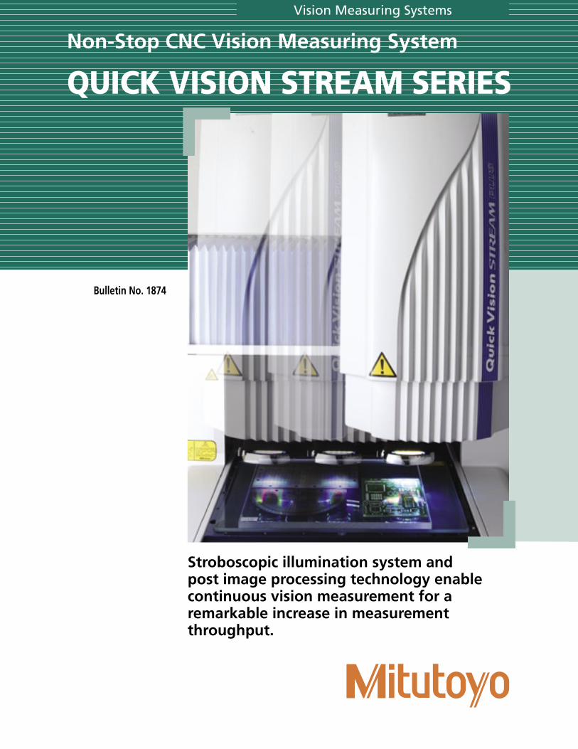
Non-Stop CNC Vision Measuring System
QUICK VISION STREAM SERIES
Stroboscopic illumination system and post image processing technology enable continuous vision measurement for a remarkable increase in measurement throughput.
2
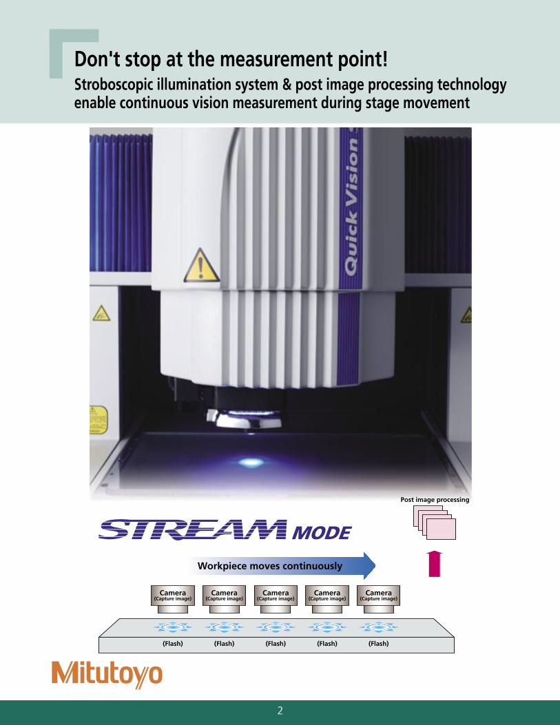
Workpiece moves continuously
Camera(Capture image)
(Flash)
Camera(Capture image)
(Flash)
Camera(Capture image)
(Flash)
Camera(Capture image)
(Flash)
Camera(Capture image)
(Flash)
Post image processing
Don't stop at the measurement point!Stroboscopic illumination system & post image processing technology enable continuous vision measurement during stage movement
3
InnovationInnovationStreaming vision measurement
Choice of models
Strobe-LED Illumination
Interference fringes
CCD
Polarizer
Polarizer
Workpiece surface
Crystal plate
Light intensitydistribution
���������������
���������������������
����������������������������������������������������������
�����������
����������������� �����
��������������
�������� ��������
���������������
���������������������
��������
���������
�������
Photodiodea
Pinhole(front)
Holo-scale
Objective
Workpiecesurface
Pinhole(rear)
Photodiodeb
Laser source
Gantry type
• Quick Vision ACCEL STREAM Plus Stream mode: 40mm/s
Standard Type Hybrid Type1• Quick Vision ACCEL STREAM
Stream mode: 5mm/s Standard Type Hybrid Type1
• Quick Vision STREAM Plus Stream mode: 40mm/s
Standard Type Hybrid Type1 Hybrid Type2• Quick Vision STREAM
Stream mode: 5mm/s Standard Type Hybrid Type1 Hybrid Type2
Moving stage type
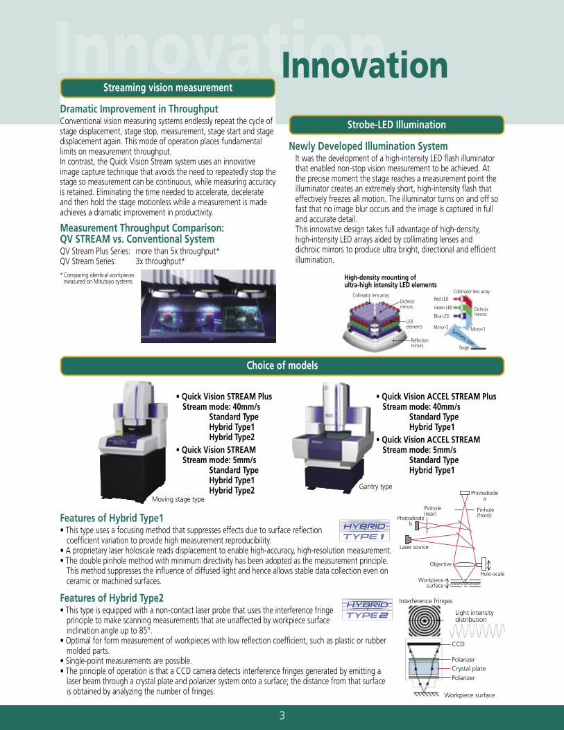
Dramatic Improvement in ThroughputConventional vision measuring systems endlessly repeat the cycle of stage displacement, stage stop, measurement, stage start and stage displacement again. This mode of operation places fundamental limits on measurement throughput. In contrast, the Quick Vision Stream system uses an innovative image capture technique that avoids the need to repeatedly stop the stage so measurement can be continuous, while measuring accuracy is retained. Eliminating the time needed to accelerate, decelerate and then hold the stage motionless while a measurement is made achieves a dramatic improvement in productivity.
Measurement Throughput Comparison: QV STREAM vs. Conventional SystemQV Stream Plus Series: more than 5x throughput*QV Stream Series: 3x throughput** Comparing identical workpieces
measured on Mitutoyo systems.
Newly Developed Illumination System It was the development of a high-intensity LED flash illuminator
that enabled non-stop vision measurement to be achieved. At the precise moment the stage reaches a measurement point the illuminator creates an extremely short, high-intensity flash that effectively freezes all motion. The illuminator turns on and off so fast that no image blur occurs and the image is captured in full and accurate detail.
This innovative design takes full advantage of high-density, high-intensity LED arrays aided by collimating lenses and dichroic mirrors to produce ultra bright, directional and efficient illumination.
Features of Hybrid Type2• This type is equipped with a non-contact laser probe that uses the interference fringe
principle to make scanning measurements that are unaffected by workpiece surface inclination angle up to 85°.
• Optimal for form measurement of workpieces with low reflection coefficient, such as plastic or rubber molded parts.
• Single-point measurements are possible.• The principle of operation is that a CCD camera detects interference fringes generated by emitting a
laser beam through a crystal plate and polarizer system onto a surface; the distance from that surface is obtained by analyzing the number of fringes.
Features of Hybrid Type1• This type uses a focusing method that suppresses effects due to surface reflection
coefficient variation to provide high measurement reproducibility.• A proprietary laser holoscale reads displacement to enable high-accuracy, high-resolution measurement.• The double pinhole method with minimum directivity has been adopted as the measurement principle.
This method suppresses the influence of diffused light and hence allows stable data collection even on ceramic or machined surfaces.
4
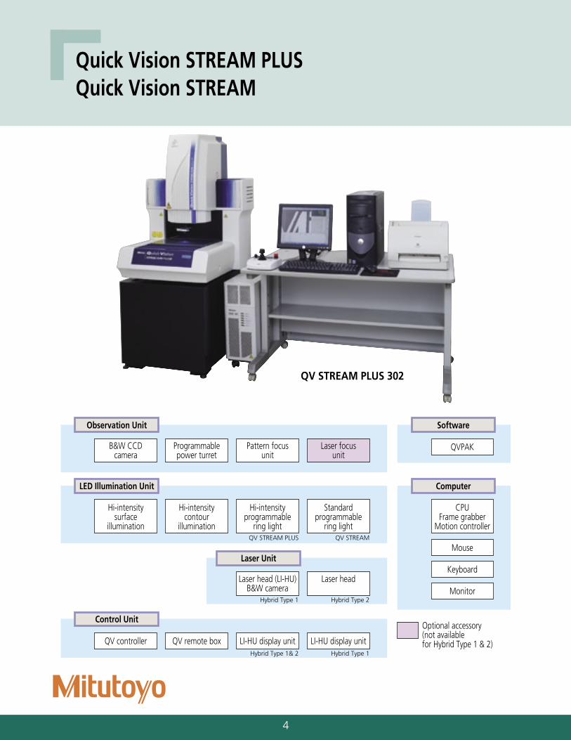
Quick Vision STREAM PLUSQuick Vision STREAM
B&W CCDcamera
Programmablepower turret
Pattern focusunit
Laser focusunit
Observation Unit
QVPAK
Software
Hi-intensitysurface
illumination
Hi-intensitycontour
illumination
Hi-intensityprogrammable
ring light
Standardprogrammable
ring light
LED Illumination Unit
CPUFrame grabber
Motion controller
Computer
Laser head (LI-HU)B&W camera
Laser head
Laser Unit
QV controller QV remote box LI-HU display unit LI-HU display unit
Mouse
Keyboard
Monitor
Control UnitOptional accessory(not available for Hybrid Type 1 & 2)
QV STREAM PLUS QV STREAM
Hybrid Type 1& 2 Hybrid Type 1
Hybrid Type 1 Hybrid Type 2
QV STREAM PLUS 302

5
Specifications
Model QV STREAM PLUS 302QV STREAM 302
QV STREAM PLUS 404QV STREAM 404
QV STREAM PLUS 606QV STREAM 606
Measuring range(XxYxZ-axis)
Normal mode camera 11.81"x7.87"x7.87"(300x200x200mm) 15.75"x15.75"x9.84"(400x400x250mm) 23.62"x25.59"x9.84"(600x650x250mm)
Normal mode (laser)
Hybrid Type 1 6.93"x7.87"x7.87"(176x200x200mm) 10.87"x15.75"x9.84"(276x400x250mm) 18.74"x25.59"x9.84"(476x650x250mm)
Hybrid Type 2 6.38"x7.68"x7.87"(162x195x200mm) 10.31"x15.55"x9.84"(262x395x250mm) 18.19"x25.39"x9.84"(462x645x250mm)
STREAM mode [camera] 11.81"x7.87"x7.87"(300x200x200mm)[11.81"x7.87"x1.97"(300x200x50mm)]-1
15.75"x15.75"x9.84"(400x400x250mm)[15.75"x15.75"x1.97"(400x400x50mm)]-1
23.62"x25.59"x9.84"(600x650x250mm)[23.62"x25.59"x1.97"(600x650x50mm)]-1
Resolution 0.1µm
Scale type Reflective linear encoder
Image detection method B&W progressive scan CCD camera
Illumination system
Surface illumination-2 Continuous (composite white, R, G, B) / stroboscopic (B) hi-intensity LED illumination, switchable
Contour illumination-2 Continuous (B) / stroboscopic (B) hi-intensity LED illumination, switchable
Programmable ring light-2, -3 Continuous (composite white, R, G, B) / stroboscopic (B) Hi-intensity LED illumination, switchableContinuous (composite white, R, G, B) standard LED illumination
Observation unit Programmable power turret
Measuring accuracyL=Measured length (mm),at 20°C±1°C
E1XY (1.5+3L/1000)µm (1.5+3L/1000)µm (1.5+3L/1000)µm
E1ZCamera (3.0+4L/1000)µm (3.0+4L/1000)µm (3.0+4L/1000)µm
Laser (Hybrid Type 1 & 2) (2.5+4L/1000)µm (2.5+4L/1000)µm (2.5+4L/1000)µm
E2XY (2.5+4L/1000)µm (2.5+4L/1000)µm (2.5+4L/1000)µm
Maximum measuring speed (X-axis, Y-axis, Z-axis) 11.81"/s(300mm/s)
Maximum measuring speed in STREAM mode 1.60"/s, .20"/s (40mm/s, 5mm/s)
Stage glass size 15.71'x10.67"(399x271mm) 19.41"x21.69"(493x551mm) 27.44"x29.84"(697x758mm)
Maximum stage loading 44 lbf.(20kgf) 88 lbf.(40kgf) 110 lbf.(50kgf)
Dimensions-4Standard & Hybrid Type 1 30.87"x33.86"x60.43"(784x860x1535mm) 40.94"x48.03"x69.49"(1040x1220x1765mm) 51.57"x73.27"x71.69"(1310x1861x1821mm)
Hybrid Type 2 30.87"x33.86"x62.91"(784x860x1598mm) 40.94"x48.03"x69.49"(1040x1220x1765mm) 51.57"x73.27"x71.69"(1310x1861x1821mm)
Main unit mass-4 844 lbs.(383kg) 1,459 lbs.(662kg) 4,074 lbs.(1848kg)
Air supply for Hybrid Type 1 & 2 0.4MPa
-1: When using contour illumination-2: Only one illumination (surface / contour / programmable ring light) is available in the STREAM mode.-3: 4-quadrant lighting or 1-quadrant lighting is available in the STREAM mode.-4: Including machine stand
Optional AccessoriesTouch probe system, Refer to page 10. • PH6 set: 02ANT840 • PH1 set: 02ANT860 • MCR rack/2-port: 02ANT30A • MCR20 rack/3-port: 02ANT30B • MCR mounting plate: 02ANT770 • Calibration ring: 02ANL920 • Master ball stand: 02ANT720Machine standCalibration plate, Refer to page 11. • For Hybrid Type 1: 02AND770 • For Hybrid Type 2: 02AKQ520 • For Hybrid Type 2: 02AKQ550*1
Laser focus unit*2, Refer to page 11.Objective, Refer to page 11. • QV-1x: 02ALA400 • QV-2.5x: 02ALA410 • QV-5x: 02ALA420 • QV-SL1x: 02ALA150 • QV-SL2.5x: 02ALA170 • QV-0.5x: 02ALG000*3
• QV-10x: 02ALG010*3
• QV-25x: 02ALG020*3
Calibration chart: 02AKN020, Refer to page 11.
*1: For the objectives of QV-0.5x, QV-10x and QV-25x.
*2: Not available for Hybrid Type 1 and 2.*3: Only for Hybrid Type 2
Inch/(mm)
6
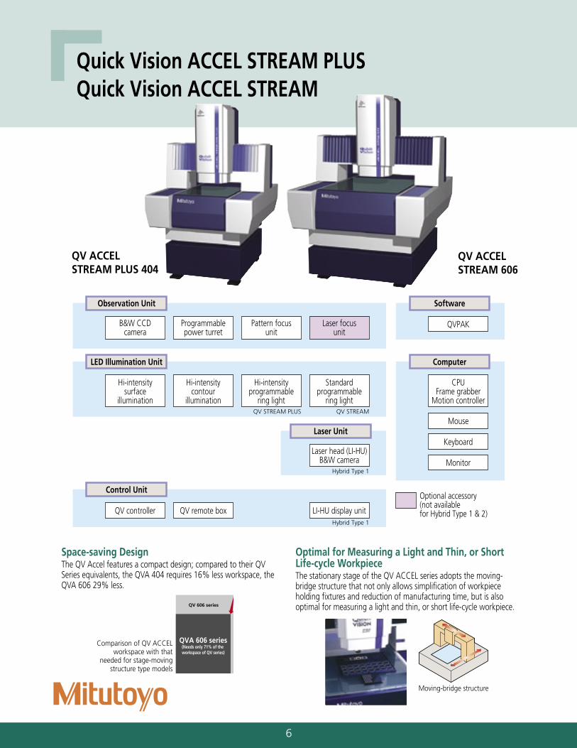
Quick Vision ACCEL STREAM PLUSQuick Vision ACCEL STREAM
QV ACCEL STREAM PLUS 404
Comparison of QV ACCEL workspace with that
needed for stage-moving structure type models
Moving-bridge structure
Optimal for Measuring a Light and Thin, or Short Life-cycle WorkpieceThe stationary stage of the QV ACCEL series adopts the moving-bridge structure that not only allows simplification of workpiece holding fixtures and reduction of manufacturing time, but is also optimal for measuring a light and thin, or short life-cycle workpiece.
Space-saving DesignThe QV Accel features a compact design; compared to their QV Series equivalents, the QVA 404 requires 16% less workspace, the QVA 606 29% less.
QV ACCEL STREAM 606
QV 606 series
QVA 606 series(Needs only 71% of the workspace of QV series)
B&W CCDcamera
Programmablepower turret
Pattern focusunit
Laser focusunit
Observation Unit
QVPAK
Software
Hi-intensitysurface
illumination
Hi-intensitycontour
illumination
Hi-intensityprogrammable
ring light
Standardprogrammable
ring light
LED Illumination Unit
CPUFrame grabber
Motion controller
Computer
Laser head (LI-HU)B&W camera
Laser Unit
QV controller QV remote box LI-HU display unit
Mouse
Keyboard
Monitor
Control UnitOptional accessory(not available for Hybrid Type 1 & 2)
QV STREAM PLUS QV STREAM
Hybrid Type 1
Hybrid Type 1
7
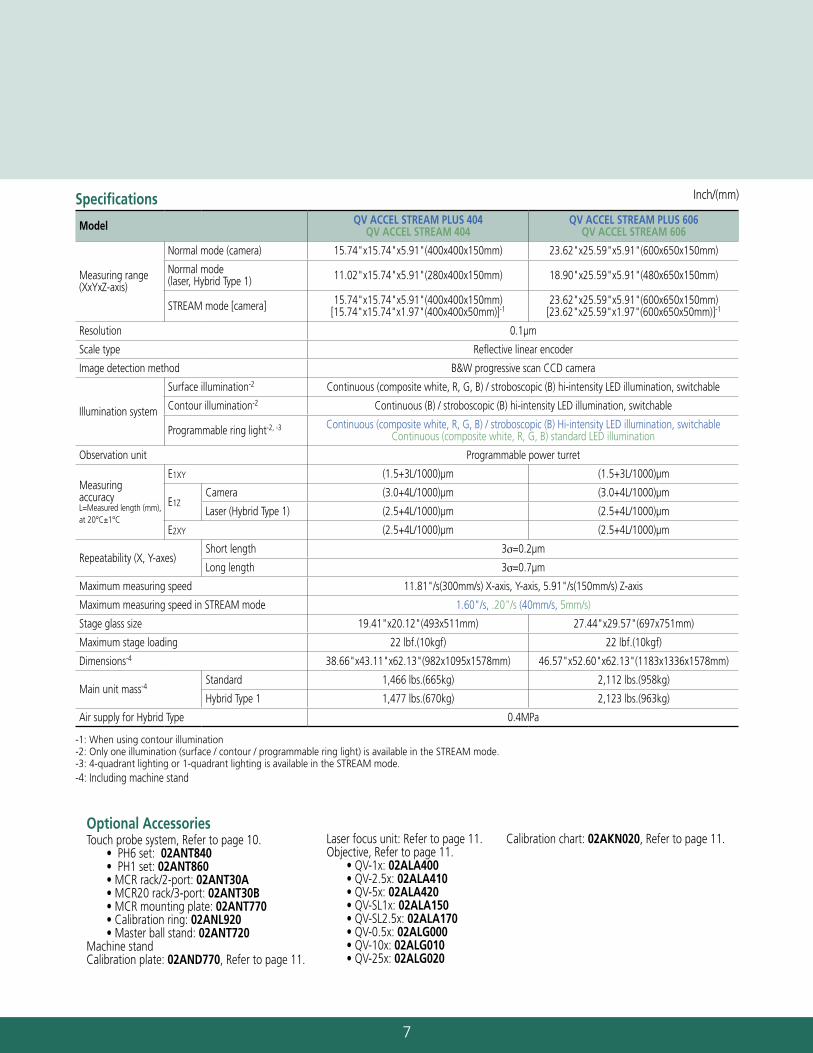
Specifications
Model QV ACCEL STREAM PLUS 404QV ACCEL STREAM 404
QV ACCEL STREAM PLUS 606QV ACCEL STREAM 606
Measuring range(XxYxZ-axis)
Normal mode (camera) 15.74"x15.74"x5.91"(400x400x150mm) 23.62"x25.59"x5.91"(600x650x150mm)
Normal mode (laser, Hybrid Type 1) 11.02"x15.74"x5.91"(280x400x150mm) 18.90"x25.59"x5.91"(480x650x150mm)
STREAM mode [camera] 15.74"x15.74"x5.91"(400x400x150mm)[15.74"x15.74"x1.97"(400x400x50mm)]-1
23.62"x25.59"x5.91"(600x650x150mm)[23.62"x25.59"x1.97"(600x650x50mm)]-1
Resolution 0.1µm
Scale type Reflective linear encoder
Image detection method B&W progressive scan CCD camera
Illumination system
Surface illumination-2 Continuous (composite white, R, G, B) / stroboscopic (B) hi-intensity LED illumination, switchable
Contour illumination-2 Continuous (B) / stroboscopic (B) hi-intensity LED illumination, switchable
Programmable ring light-2, -3 Continuous (composite white, R, G, B) / stroboscopic (B) Hi-intensity LED illumination, switchableContinuous (composite white, R, G, B) standard LED illumination
Observation unit Programmable power turret
Measuring accuracyL=Measured length (mm), at 20°C±1°C
E1XY (1.5+3L/1000)µm (1.5+3L/1000)µm
E1ZCamera (3.0+4L/1000)µm (3.0+4L/1000)µm
Laser (Hybrid Type 1) (2.5+4L/1000)µm (2.5+4L/1000)µm
E2XY (2.5+4L/1000)µm (2.5+4L/1000)µm
Repeatability (X, Y-axes)Short length 3σ=0.2µm
Long length 3σ=0.7µm
Maximum measuring speed 11.81"/s(300mm/s) X-axis, Y-axis, 5.91"/s(150mm/s) Z-axis
Maximum measuring speed in STREAM mode 1.60"/s, .20"/s (40mm/s, 5mm/s)
Stage glass size 19.41"x20.12"(493x511mm) 27.44"x29.57"(697x751mm)
Maximum stage loading 22 lbf.(10kgf) 22 lbf.(10kgf)
Dimensions-4 38.66"x43.11"x62.13"(982x1095x1578mm) 46.57"x52.60"x62.13"(1183x1336x1578mm)
Main unit mass-4Standard 1,466 lbs.(665kg) 2,112 lbs.(958kg)
Hybrid Type 1 1,477 lbs.(670kg) 2,123 lbs.(963kg)
Air supply for Hybrid Type 0.4MPa
-1: When using contour illumination-2: Only one illumination (surface / contour / programmable ring light) is available in the STREAM mode.-3: 4-quadrant lighting or 1-quadrant lighting is available in the STREAM mode.-4: Including machine stand
Optional AccessoriesTouch probe system, Refer to page 10. • PH6 set: 02ANT840 • PH1 set: 02ANT860 • MCR rack/2-port: 02ANT30A • MCR20 rack/3-port: 02ANT30B • MCR mounting plate: 02ANT770 • Calibration ring: 02ANL920 • Master ball stand: 02ANT720Machine standCalibration plate: 02AND770, Refer to page 11.
Laser focus unit: Refer to page 11.Objective, Refer to page 11. • QV-1x: 02ALA400 • QV-2.5x: 02ALA410 • QV-5x: 02ALA420 • QV-SL1x: 02ALA150 • QV-SL2.5x: 02ALA170 • QV-0.5x: 02ALG000 • QV-10x: 02ALG010 • QV-25x: 02ALG020
Calibration chart: 02AKN020, Refer to page 11.
Inch/(mm)
8
30.87"(784)
60.4
3"(1
535)
31.5
0"(8
00) 9.25
"(2
35)
22.2
4"(5
65)
17.32" (440) support leg
23.23"(590)
28.90"(734)
25.67"(652) support leg
31.85"(809) 1.97"(50)
33.86"(860)
47.24"(1200)
27.5
6"(7
00)
47.24"(1200)
27.5
6"(7
00)
40.94"(1040)
69.4
9"(1
765)
54.6
5"(1
388)
31.8
1"(8
08)
16.9
7"(4
31)
14.8
4"(3
77)
21.65"(550) support leg 27.17"(690) support leg
26.77"(680)
35.04"(890)
34.65"(880)
48.03"(1220)
47.24"(1200)
27.5
6"(7
00)
51.57"(1310)
71.6
9"(1
821)
62.2
8"(1
582)
33.9
8"(8
63)
24.5
7"(6
24)
9.41
"(2
39)
29.13"(740) support leg
36.10"(917)
45.67"(1160)
40.47"(1028) support leg
60.55"(1538)
36.81"(935)
73.27"(1861)
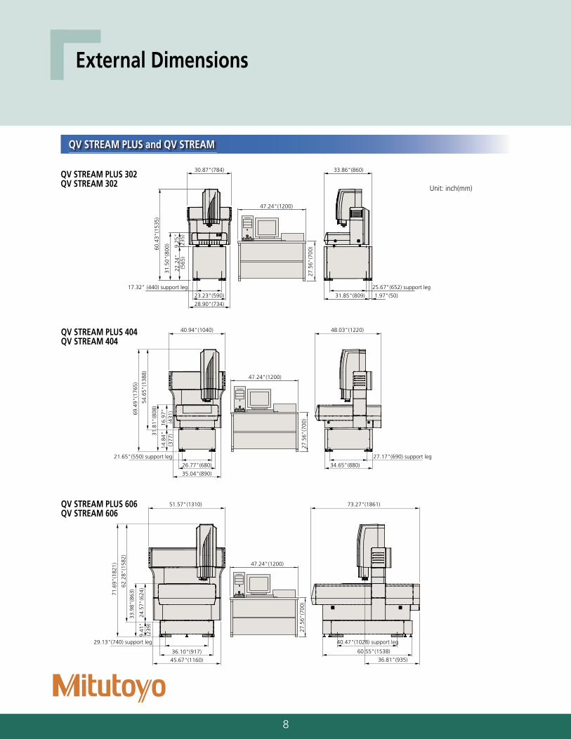
QV STREAM PLUS 302QV STREAM 302
QV STREAM PLUS 404QV STREAM 404
QV STREAM PLUS 606QV STREAM 606
Unit: inch(mm)
QV STREAM PLUS and QV STREAM
External Dimensions
9
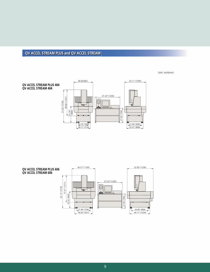
QV ACCEL STREAM PLUS 404QV ACCEL STREAM 404
QV ACCEL STREAM PLUS 606QV ACCEL STREAM 606
Unit: inch(mm)
38.66(982) 43.11"(1095)
19.76"(502)
28.11"(714)
27.40"(696)
33.31"(846)
31.5
0"(1
578)
48.8
6"(1
241)
31.5
0"(8
00)
47.24"(1200)
27.5
6"(7
00)
46.57"(1183) 52.60"(1336)
27.80"(706)
36.65"(931)
34.80"(884)
40.71"(1034)
62.1
3"(1
578)
51.6
1"(1
311)
31.5
0"(8
00)
47.24"(1200)
27.5
6"(7
00)
QV ACCEL STREAM PLUS and QV ACCEL STREAM
10
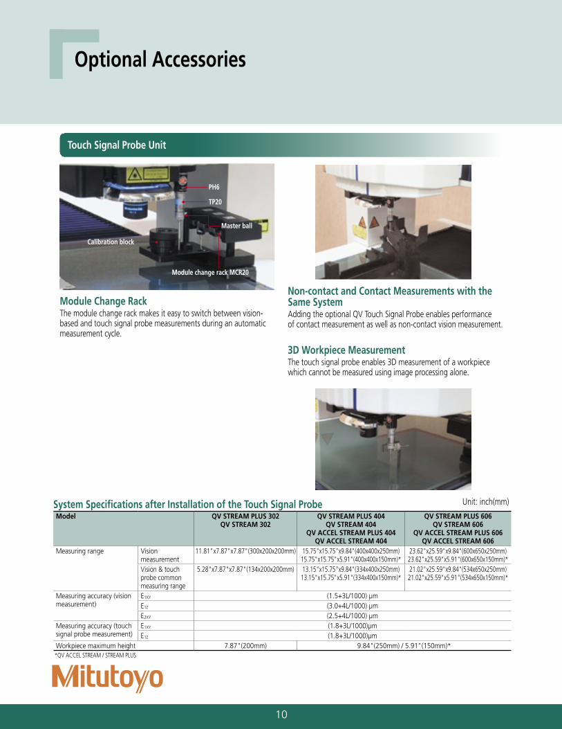
Optional Accessories
Non-contact and Contact Measurements with the Same System Adding the optional QV Touch Signal Probe enables performance of contact measurement as well as non-contact vision measurement.
3D Workpiece MeasurementThe touch signal probe enables 3D measurement of a workpiece which cannot be measured using image processing alone.
Module Change RackThe module change rack makes it easy to switch between vision-based and touch signal probe measurements during an automatic measurement cycle.
Touch Signal Probe Unit
System Specifications after Installation of the Touch Signal ProbeModel QV STREAM PLUS 302
QV STREAM 302QV STREAM PLUS 404
QV STREAM 404QV ACCEL STREAM PLUS 404
QV ACCEL STREAM 404
QV STREAM PLUS 606QV STREAM 606
QV ACCEL STREAM PLUS 606QV ACCEL STREAM 606
Measuring range Vision measurement
11.81"x7.87"x7.87"(300x200x200mm) 15.75"x15.75"x9.84"(400x400x250mm)15.75"x15.75"x5.91"(400x400x150mm)*
23.62"x25.59"x9.84"(600x650x250mm)23.62"x25.59"x5.91"(600x650x150mm)*
Vision & touch probe common measuring range
5.28"x7.87"x7.87"(134x200x200mm) 13.15"x15.75"x9.84"(334x400x250mm)13.15"x15.75"x5.91"(334x400x150mm)*
21.02"x25.59"x9.84"(534x650x250mm)21.02"x25.59"x5.91"(534x650x150mm)*
Measuring accuracy (vision measurement)
E1XY (1.5+3L/1000) µmE1Z (3.0+4L/1000) µmE2XY (2.5+4L/1000) µm
Measuring accuracy (touch signal probe measurement)
E1XY (1.8+3L/1000)µmE1Z (1.8+3L/1000)µm
Workpiece maximum height 7.87"(200mm) 9.84"(250mm) / 5.91"(150mm)**QV ACCEL STREAM / STREAM PLUS
Master ball
Calibration block
PH6
TP20
Module change rack MCR20
Unit: inch(mm)
11
Coaxial laser auto-focus
Detector a
Pinhole
Objective
Detector b
Pinhole
Lens
Half mirror
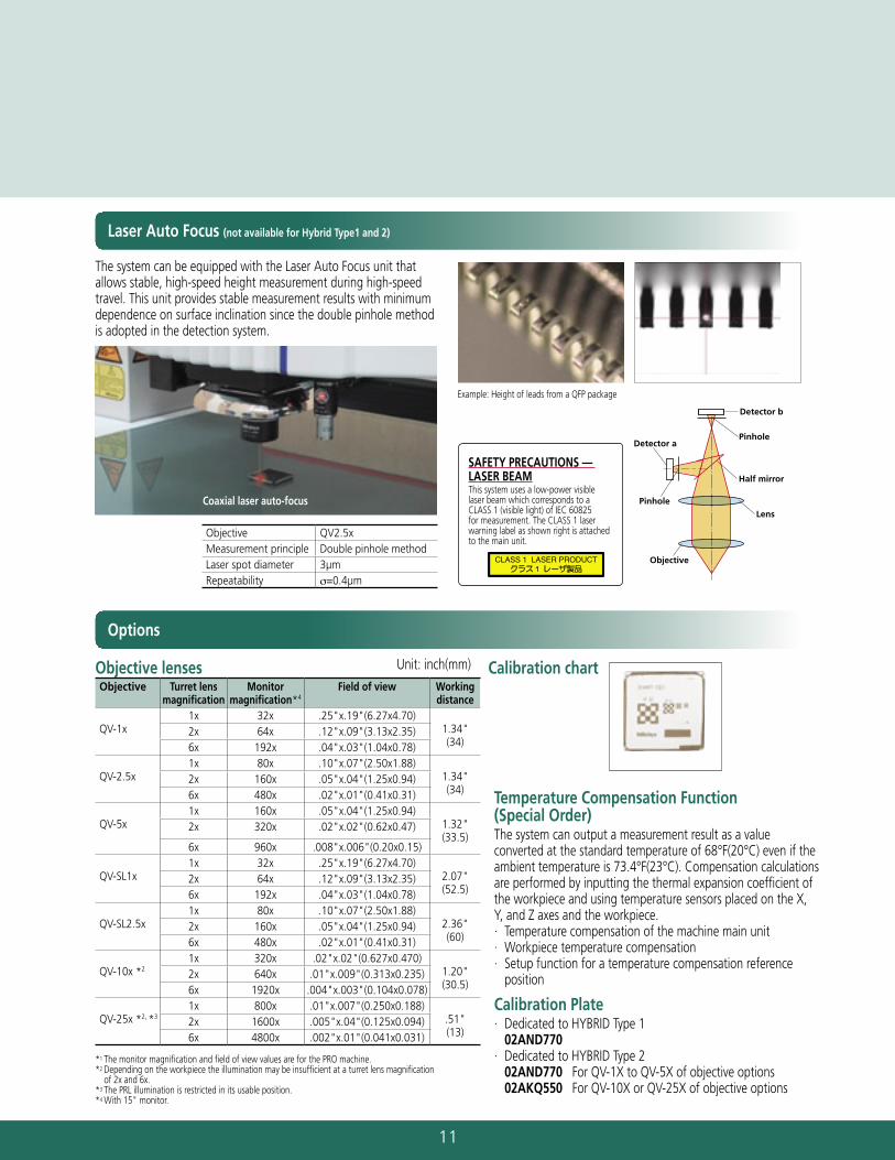
The system can be equipped with the Laser Auto Focus unit that allows stable, high-speed height measurement during high-speed travel. This unit provides stable measurement results with minimum dependence on surface inclination since the double pinhole method is adopted in the detection system.
Objective lensesObjective Turret lens
magnificationMonitor
magnification*4Field of view Working
distance
QV-1x1x 32x .25"x.19"(6.27x4.70)
1.34"(34)
2x 64x .12"x.09"(3.13x2.35)6x 192x .04"x.03"(1.04x0.78)
QV-2.5x1x 80x .10"x.07"(2.50x1.88)
1.34"(34)
2x 160x .05"x.04"(1.25x0.94)6x 480x .02"x.01"(0.41x0.31)
QV-5x1x 160x .05"x.04"(1.25x0.94)
1.32"(33.5)
2x 320x .02"x.02"(0.62x0.47)
6x 960x .008"x.006"(0.20x0.15)
QV-SL1x1x 32x .25"x.19"(6.27x4.70)
2.07"(52.5)
2x 64x .12"x.09"(3.13x2.35)6x 192x .04"x.03"(1.04x0.78)
QV-SL2.5x1x 80x .10"x.07"(2.50x1.88)
2.36"(60)
2x 160x .05"x.04"(1.25x0.94)6x 480x .02"x.01"(0.41x0.31)
QV-10x *21x 320x .02"x.02"(0.627x0.470)
1.20"(30.5)
2x 640x .01"x.009"(0.313x0.235)6x 1920x .004"x.003"(0.104x0.078)
QV-25x *2, *31x 800x .01"x.007"(0.250x0.188)
.51"(13)
2x 1600x .005"x.04"(0.125x0.094)6x 4800x .002"x.01"(0.041x0.031)
*1 The monitor magnification and field of view values are for the PRO machine.*2 Depending on the workpiece the illumination may be insufficient at a turret lens magnification
of 2x and 6x.*3 The PRL illumination is restricted in its usable position.*4 With 15" monitor.
Calibration chart
Example: Height of leads from a QFP package
Objective QV2.5xMeasurement principle Double pinhole methodLaser spot diameter 3µmRepeatability σ=0.4µm
SAFETY PRECAUTIONS — LASER BEAMThis system uses a low-power visible laser beam which corresponds to a CLASS 1 (visible light) of IEC 60825 for measurement. The CLASS 1 laser warning label as shown right is attached to the main unit.
Laser Auto Focus (not available for Hybrid Type1 and 2)
Options
Temperature Compensation Function (Special Order)The system can output a measurement result as a value converted at the standard temperature of 68°F(20°C) even if the ambient temperature is 73.4°F(23°C). Compensation calculations are performed by inputting the thermal expansion coefficient of the workpiece and using temperature sensors placed on the X, Y, and Z axes and the workpiece.· Temperature compensation of the machine main unit· Workpiece temperature compensation· Setup function for a temperature compensation reference
position
Calibration Plate· Dedicated to HYBRID Type 1
02AND770· Dedicated to HYBRID Type 2
02AND770 For QV-1X to QV-5X of objective options 02AKQ550 For QV-10X or QV-25X of objective options
Unit: inch(mm)
12
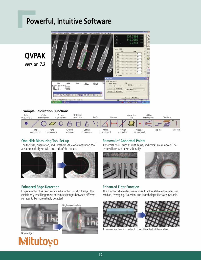
QVPAK version 7.2
Powerful, Intuitive Software
Point measurement
Line measurement
Plane measurement
Cylinder with step
Conical measurement
Angle measurement
Point of intersection
Midpoint measurement
Step line End face
Circle measurement
Sphere measurement
Cylindrical measurement Buffer Distance
Intersection line
Midline measurement Step face
Example Calculation Functions
One-click Measuring Tool Set-upThe tool size, orientation, and threshold value of a measuring tool are automatically set with one click of the mouse.
Removal of Abnormal PointsAbnormal points such as dust, burrs, and cracks are removed. The removal level can be set arbitrarily.
Noisy edge
Brightness analysis
Enhanced Edge-Detection Edge-detection has been enhanced enabling indistinct edges that exhibit only small brightness or texture changes between different surfaces to be more reliably detected.
Enhanced Filter FunctionThis function eliminates image noise to allow stable edge detection.Median, Averaging, Gaussian, and Morphology filters are available.
A preview function is provided to check the effect of these filters.
13
Example of batch measurement of 192 (16 x 12) points
Example of display with the QV graphics
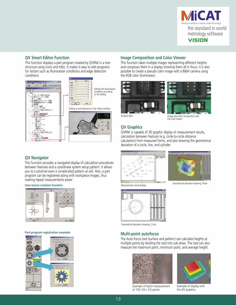
Editing the illumination condition according to the dialog
Editing a tool directory on the Video window
QV Smart Editor FunctionThis function displays a part program created by QVPAK in a tree structure using icons and titles. It makes it easy to edit programs for factors such as illumination conditions and edge detection conditions.
User-macro creation function
Part-program registration example
QV NavigatorThis function provides a navigated display of calculation procedures between features and a coordinate system setup pattern. It allows you to customize even a complicated pattern at will. Also, a part program can be registered along with workpiece images, thus making repeat measurements easier.
Original data Image data after composition with the color viewer
Image Composition and Color ViewerThis function takes multiple images representing different heights and composes them in a display showing them all in focus. It is also possible to create a pseudo color image with a B&W camera using the RGB color illumination.
Measurement result displayGeometrical deviation drawing: Plane
Geometrical deviation drawing: Circle
QV GraphicsQVPAK is capable of 3D graphic display of measurement results, calculation between features (e.g. circle-to-circle distance calculation) from measured forms, and also drawing the geometrical deviation of a circle, line, and cylinder.
Multi-point autofocusThe Auto Focus tool (surface and pattern) can calculate heights at multiple points by dividing the tool into sub areas. The tool can also measure the maximum point, minimum point, and average height.
14
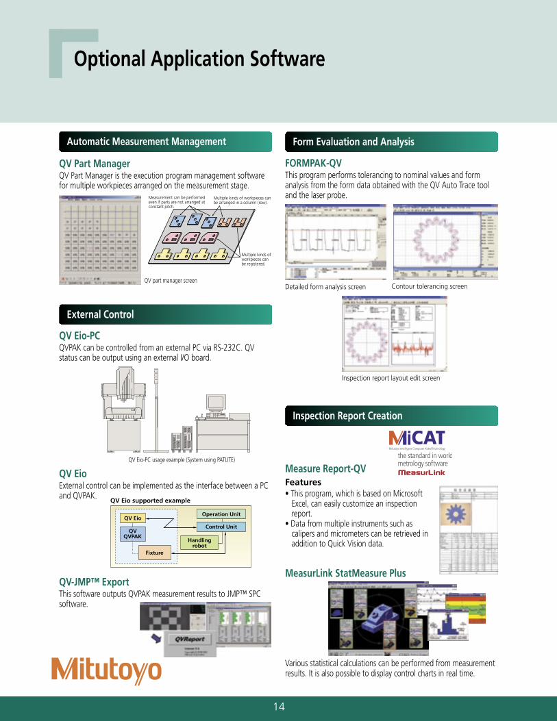
Optional Application Software
QV Part ManagerQV Part Manager is the execution program management software for multiple workpieces arranged on the measurement stage.
FORMPAK-QVThis program performs tolerancing to nominal values and form analysis from the form data obtained with the QV Auto Trace tool and the laser probe.
QV part manager screenContour tolerancing screenDetailed form analysis screen
Inspection report layout edit screen
Automatic Measurement Management Form Evaluation and Analysis
QV Eio-PC usage example (System using PATLITE)
QV EioExternal control can be implemented as the interface between a PC and QVPAK.
QV Eio-PCQVPAK can be controlled from an external PC via RS-232C. QV status can be output using an external I/O board.
QV-JMP™ ExportThis software outputs QVPAK measurement results to JMP™ SPC software.
External Control
Measure Report-QVFeatures• This program, which is based on Microsoft
Excel, can easily customize an inspection report.
• Data from multiple instruments such as calipers and micrometers can be retrieved in addition to Quick Vision data.
MeasurLink StatMeasure Plus
Various statistical calculations can be performed from measurement results. It is also possible to display control charts in real time.
Inspection Report Creation
Measurement can be performed even if parts are not arranged at constant pitch.
Multiple kinds of workpieces can be registered.
Multiple kinds of workpieces can be arranged in a column (row).
QV Eio supported example
QV Eio
QVQVPAK
Fixture
Handlingrobot
Operation Unit
Control Unit
15
for Hybrid Type1/2 only for Hybrid Type1/2 only
for Hybrid Type1/2 only for Hybrid Type1/2 only
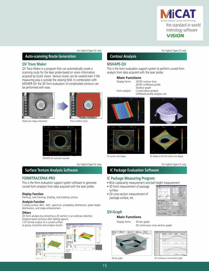
QV Trace MakerQV Trace Maker is a program that can automatically create a scanning route for the laser probe based on vision information acquired by Quick Vision. Various routes can be created even if the measuring area is outside the viewing field. In combination with MSHAPE-QV the 3D form evaluation of complicated contours can be performed with ease.
Trace condition setupTarget area image composition
MSHAPE-QV evaluation example
Auto-scanning Route Generation
Surface Texture Analysis Software
Main FunctionsDisplay forms 2D/3D contour lines 2D/3D unfiltered profile Shadow graphForm analysis Curved plane analysis Unfiltered profile analysis, etc.
MSHAPE-QVThis is the form evaluation support system to perform curved form analysis from data acquired with the laser probe.
QV-GraphMain Functions Display forms 3D bar graph 2D continuous cross-section graph
2D contour line display 3D display of the 2D contour line display
3D bar graph 2D continuous cross-section graph
IC Package Measuring Program• BGA coplanarity measurement and ball height measurement• 3D form measurement of package
surface• 2D cross-section measurement of
package surface, etc.
Contour Analysis
IC Package Evaluation Software
FORMTRACEPAK-PROThis is the form evaluation support system software to generate curved form analyses from data acquired with the laser probe.
Display FunctionPainting, wire framing, shading, and shading contour
Analysis FunctionCutting surface, BAC, ADC, spectrum, probability distribution, peak height distribution, and slope enhancement
Others2D form analysis by extracting a 2D section in an arbitrary direction Original report printout after editing layoutsCSV format output of a curved surface (a group of points) and analysis results
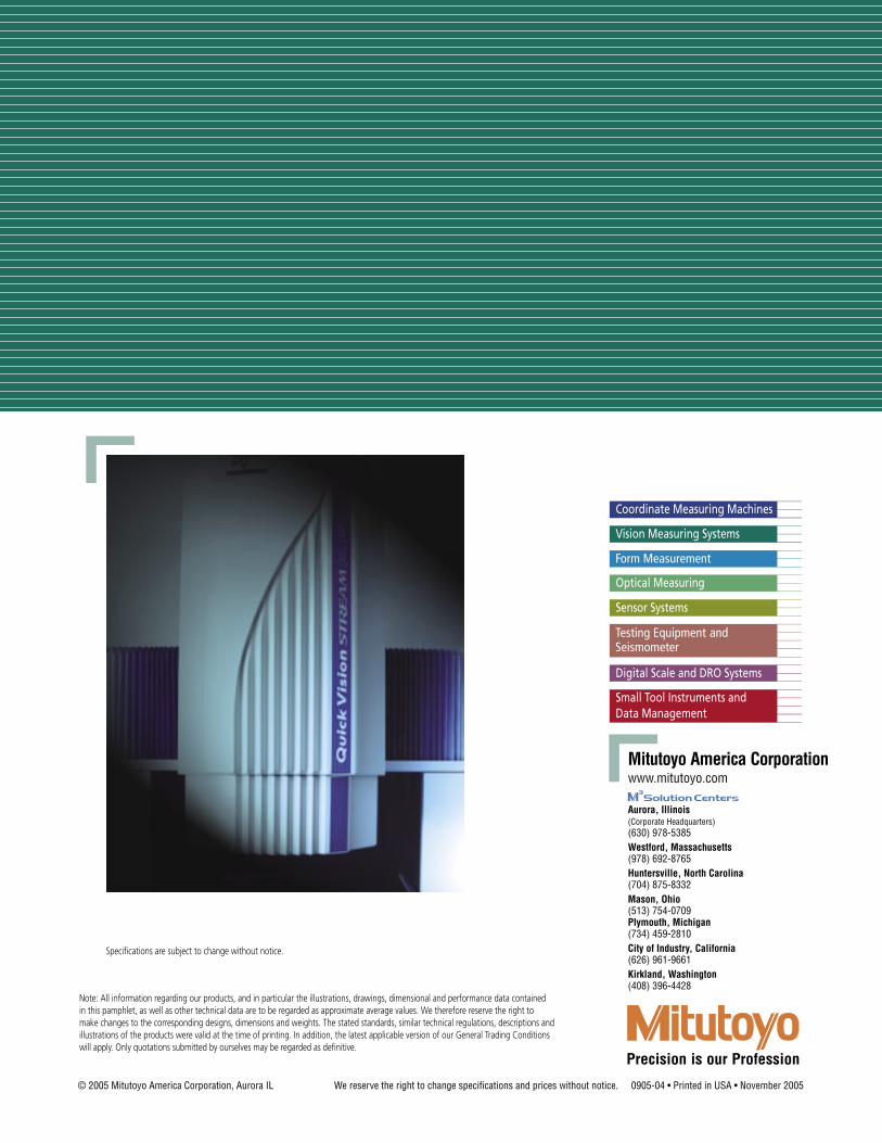
Vision Measuring Systems
Aurora, Illinois(Corporate Headquarters)(630) 978-5385Westford, Massachusetts(978) 692-8765Huntersville, North Carolina(704) 875-8332Mason, Ohio(513) 754-0709Plymouth, Michigan(734) 459-2810City of Industry, California(626) 961-9661Kirkland, Washington(408) 396-4428
© 2005 Mitutoyo America Corporation, Aurora IL We reserve the right to change specifications and prices without notice. 0905-04 • Printed in USA • November 2005
Note: All information regarding our products, and in particular the illustrations, drawings, dimensional and performance data contained in this pamphlet, as well as other technical data are to be regarded as approximate average values. We therefore reserve the right to make changes to the corresponding designs, dimensions and weights. The stated standards, similar technical regulations, descriptions and illustrations of the products were valid at the time of printing. In addition, the latest applicable version of our General Trading Conditions will apply. Only quotations submitted by ourselves may be regarded as definitive.
Specifications are subject to change without notice.