non-polluting composites repair and … research laboratory aberdeen proving ground, md 21005-5069...
TRANSCRIPT

Army Research Laboratory Aberdeen Proving Ground, MD 21005-5069
ARL-TR-2457 April ‘2001
Non-Polluting Composites Repair and Remanufacturing for Military Applications: Induction-Based Processing
Bruce K. Fink, Nicholas B. Shevchenko, and James M. Sands Weapons and Materials Research Directorate, ARL
Shridhar Yarlagadda and John W. Gillespie, Jr. University of Delaware
Approved for public release; distribution is unlimited.

Abstract
The development of induction-based processing of carbon-fiber (CF) thermoplastic-matrix composites and accelerated cure of thermosetting adhesives has the potential to provide nonautoclave processing technology for manufacturing and repair of polymer-matrix composites (PMCs). In this report, the results of recent tests demonstrating bonding of composites. using commercial off-the-shelf thermal-cure adhesives that are heat cured via an induction field using an inductive susceptor are discussed. This method of cure utilizes heat generation within metal screen-based susceptors to cure the adhesive makx via a heat transfer mechanism. The mechanical-performance of these bonds is presented in comparison with autoclave and thermally cured baselines. No substantial loss of mechanical lap-shear strength is observed in adhesive bonds processed by induction. In addition, an example of induction welding of a thermoplastic-impregnated carbon fiber (A!%) is presented. In order to successfully demonstrate induction welding for manufacture of CF composites, the degradation of the polymer in the laminates is also investigated. No measurable degradation of the polymer, either by dielectric or thermal breakdown when heated by induction, was observed.
ii

Acknowledgments
This research was supported in part by the U.S. Department of Defense through the Strategic Environmental Research and Development Program (SERDP) under contract to the US. Army Research Laboratory (ARL) under the Non-Polluting Composites Repair and Remanufacturing for Military Applications program.
. . . lu

iv
Contents
Acknowledgments . I .
111.
List of Figures vii
List of Tables ix
1. Introduction
2. Induction-Based Repair and Remanufacturing 1
2.1 Induction-Based Repair of Multifunctional Composite Armor. .............. 2
2.1.1 Material Systems ............................................................................... 3
2.1.2 Induction Bonding Setup ................................................................. 4
2.1.3 Mechanical Performance .................................................................. 7
2.1.4 Conclusions to Induction-Based Adhesive Bonding.. .................. 9
2.2 Induction-Based Remanufacture of Thermoplastic Composite Laminates .................................................................................................................. 9
2.2.1 Heating Mechanisms for Carbon/Thermoplastics ..................... 10
2.2.1.1 Theo&id Heating Model ............................................. 11
2.2.1.2 Joule Heating of Carbon Fibers [15,X] ........................ 13
2.2.1.3 Dielectric Hysteresis Heating at Fiber Junctions.. ..... ..13
2.2.1.4 Heat Generated by Fiber Contact Resistance ............... 14
2.2.1.5 Material Properties .......................................................... 15
2.2.1.6 Two-Ply Heating Model ................................................. -15
2.2.1.7 Two-Ply Model Results ................................................... 16
2.2.1.8 Through-Thickness Heating ........................................... 18
2.2.2 Degradation Studies ........................................................................ 19
2.2.2.1 Thermal Degradation Study ........................................... 20
2.2.2.2 Weight Loss Measurements ............................................ 20
2.2.2.3 Molecular Weight Characterization .............................. 21
2.2.2.4 Electrical Degradation Study ......................................... .23
2.2.2.5 Mechanical Performance ................................................. 24
2.2.3 Induction Coil Design ..................................................................... 25
V

2.2.3.1 Laminator Coil Design . . . . . . . . . . . . . . . ..__.._.............................. 25
2.2.4 Conclusions to Induction-Based Thermoplastic Composite Lamination . . . . ..____....._.................--......................*..-.-.-.*...........*--.-..............*.. 25
3. References
Distribution List
Report Documentation Page
27
29
47
vi

r. Figure 3. Induction coil motion direction and configuration. . . . . . . . . . . ..+_...........-.-....... 5
Figure 4. Typical bondline temperature profile along the coil motion direction . . . . . ..*....~..__...*.......___.~~...._*............~....~~***..~....f.~.......~...........~....~..........~~........ 5 .
Figure 5. Mechanical performance for SW-2214 adhesive system cured at 250 “F. (A-H are defined in Tables 1 and 2). __..f.~.._..............__f........_.._......~~...~.~.... 8
Figure 6. Mechanical performance for FM300K adhesive system cured at 350 “F. .......................................................................................................................... 8
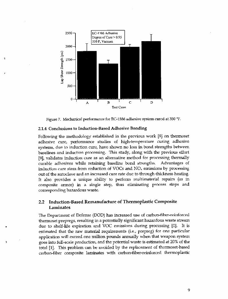
Figure 7. Mechanical performance for EC-1386 adhesive system cured at 350 “F ........................................................................................................................... 9
Figure 8. Schematic of the induction heating process for carbon/ thermoplastic composites- ...................................................................................... 10
Figure 9. Schematic of induced voltage loops in the composite.. ........................... 12
Figure 10. Heating mechanisms in each individual conductive loop.. .................. 12
Figure 11. Circuit model for dielectric heating. ...................................................... 1.14
Figure 12. Circuit model for heating by fiber contact resistance. ........................... 14
Figure 13. Dielectric properties of PEI (ultem 1000, GE plastics). .......................... 15
.Figme 14. Schematic of a 2-ply heating model. . . . . . . ..___............__............._..........____... 16
Figure 15. Comparison of heating patterns for [O/90] 2-ply stack. . . . . . . . . . . . . . . . . . ..__... 17
Figure 16. Comparison of heating patterns for [O/45] 2-ply stack. . ..___._........____... 17
Figure 17. Model through-thickness heat generation of an 8-ply carbon- fiber laminate with orientation [O/90/O/-90]5. __.+.....___ _ __ __......,f.._.____.f.......____f..... 18
Figure 18. Predicted through-thickness temperature profiles at various time steps. ______....~...._.__.___..f....__.......___....,..~.~......_____f........_____.......~.~~~..~~........____.~~f.f.. 19
Figure 19. TGA weight loss profile for PEI resin and prepreg (heating rate = 15 ‘C/min> _..........f___.......-.-......-.-*......--.-......--._..........._f______........*.-.-......---... -21
Figure 20. Breakdown voltage measurements for neat PEI films . ..__..........____....___. 24
Figure 21. Process schematic of lamination stage in a production line. . . . ..____....___ 26
Figure 22. Schematic of rectangular coil for lamination stage. ............................... 26
Figure 23. Temperature profiles of S-ply stack with rectangular coil 26 ....................
vii
List of Figures
Figure 1. Multifunctional composite armor. __.... ..___ . . . . . . . . . ..:. . . . . . . . .._............. ____+......__.... 3
Figure 2. Specimen configuration during induction bonding. . . . . . . . . . . ..__...........-.....+. 4

. . vlll

List of Tables
Table 1. Baselines for comparison with induction bonding. ..................................... 6
Table 2. Test cases for induction bonding. ................................................................... 7
Table 3. Experimental data of neat ultem 1000 resin under various heat treatments. ........................................................................................................... -22
Table 4. Degradation study of PEI and A%/PEI prepreg using GPC ................... 23
Table 5. Comparison of mechanical properties. ___......._... e . . . . ..__..........._..-.................. 25
ix

INTENTIONALLY um BLANK.
X
1. Introduction
The U.S. Army is currently pursuing the development of low-cost nonautoclave manufacturing technologies for polymer-matrix composites (PMCs) that will allow the U.S. military and contractors to prepare high-performance composites for armor, munition, and vehicle applications with reduced costs, reduced environmental impact, and increased efficiency. The authors have previously introduced the concept of induction-based processing and the environmental impacts for Army applications [l]. The initial repair demonstrations involved heat generation using a metallic (electrically conductive) mesh to translate electiomagnetic energy into thermal energy at an adhesive bond line. In this report, the background and physics of induction processing in carbon-fiber thermoplastic laminates is reviewed and the successful development of induction healing that allows suitable repair of many composite stictures is discussed. Specifically, the adhesive bonding using susceptor-based induction heating, susceptorless induction-based carbon-fiber laminate consolidation, and development of process models for electromagnetic heating of carbon-fiber composites, including heat generation by carbon fibers, metal-mesh susceptors, and magnetoresistive particles is discussed.
2. Induction-Based Repair and Remanufacturing
The search for cost-effective environmentally friendly manufacturing methods has led to the study of induction heating for bonding and processing of composites [l]. Electromagnetic cure methods involve using induction or electrical resistance heating focused directly at the material to be cured. Induction heating occurs when a current-carrying body, or coil, is placed near another conductor, the susceptor material. The magnetic field caused by the current in the coil induces a current in the susceptor. This induced current causes the susceptor to heat due to Joule heating, and, in the case of a ferromagnetic material, due to hysteresis losses. Carbon-fiber reinforcement in composite materials can function as the susceptor. For other material systems, the susceptor is a metallic mesh or magnetic particles. Energy can be introduced into the precise region to be cured both in the plane of the structure and at the specific depth required [2].
The ability of induction heating to rapidly process carbon-fiber-based thermoplastic composites is a significant environmental asset. Assuming that the
1

thermoplastic composite meets the performance and quality requirements of an equivalent thermoset counterpart, one can replace the limited shelf-life thermoset with the unlimited shelf-life thermoplastic. This completely eliminates hazardous raw material wastes at the production level resulting from shelf-life expiration and raw-material overages associated with thermoset-based composites production.
Other advantages of induction include reduction of volatile organic compounds (VOCs) and nitrous oxide (NO ) X emissions by processing out of the autoclave, localizing processing controls for repair and remanufacturing, and eliminating processing steps. In addition, induction offers internal noncontact heating; the possibility of a moving heat source (the coil) to heat large areas; high efficiency; control of the heat generation by coil design or by susceptor design; and powerful, portable, and easy-to-operate units [3,4].
2.1 Induction-Based Repair of Multifunctional Composite Armor
This research is motivated by the expanding use of multifunctional hybrid materials in military ground vehicles and the increasing need for field-expedient and depot-level repair procedures for these thick-section components.
The critical issue in adhesive-based repair of composites is the application of sufficient heat and pressure at the bond line. It is highly desirable that thermal generation be localized at the bond line and be evenly distributed (taking into account thermal conductive losses). This is especially important with the increasing use of multifunctional hybrid composites, such as composite armor. These composites typically have several layers, each serving a different function, as shown in Figure 1. Repair of such a thick-section composite will require heating locally at the appropriate bond lines; one such method is induction heating [5,4]. In addition, due to the noncontact nature of induction heating, it may be possible to bond several layers at the same time, which reduces hazardous waste, energy consumption, arid repair times for the part. Conventional repair techniques (e.g., heat blankets) will require bonding of one layer at a t&e, resulting in multiple potential hazardous waste streams such as trim, consumables, and VOC emissions.
While the induction-based repair procedure has the potential to reduce hazardous waste, it is essential that the repaired part meet the performance requirements dictated by the application. Hence, the initial work done under the program focuses on evaluating the performance of induction-based repair procedures. The goal is to obtain performance similar to that achieved with conventional repair procedures-
Recent studies [I, 7, 81 have shown similar properties for induction-heated adhesive bonds compared to baselines for room-temperature adhesives. Electrically conductive mesh susceptors and epoxy-based adhesives were used.
2


significantly from bond line temperatures due to the good thermal conduction of carbon fibers; this was confirmed by thermocouple measurements. For glass/vinyl ester, differentials of up to *lO “C between the bond line and surface were noted. Further refinements to determine the ideal motion velocity and pattern for minimal temperature gradients are in progress.
For a carbon/epoxy substrate or adherend, no susceptor is necessary. However, bonding tests were performed for both cases (i.e., with and without the mesh susceptor) to assess the presence of the mesh on bond strengths. For the carbon/epoxy substrate, all three adhesive systems were induction bonded, with and without the mesh. For the glass/vinyl-ester system, the SW-2214 adhesive was induction bonded with the mesh, as the cure cycle of the other systems (350 “F) could cause degradation in the substrate. All the induction-bonded specimens were fabricated under vacuum pressure. Table 1 lists the baselines; Table 2 lists the test cases.
Table 1. Baselines for comparison with induction bonding.
I I ( Number of T -~-- I I Case Substrate Specimens Adhesive Cure Cycle
A Carbon/Epoxy 6 SW-2214 250 “F, Vacuum B SW-2214 + mesha 60 min A Carbon/Epoxy 6 EC-1386 350 “F, Vacuum B EC-1386 + mesh 6omin A FMSOOK 350 “F, Vacuum B FM3OOK f mesh 6Omin
Carbon/Epoxy 6 E FMSOOK 350 “F, 40 psi F FM300K + mesh 6Omin-
G Glass/Vinyl Ester 6 SW-2214 250 “F, Vacuum
SW-2214 + mesh 6Omin aMesh = SS304,30 x 30,0.0075-in wire.
Baseline lap-shear specimens were fabricated according to the manufacturer’s recommended cure cycles. For the FM300K adhesive system, two pressures were considered: vacuum (-15 psi) and 40 psi. For aII other autoclave specimens, vacuum pressure was used. This allows for direct comparison with induction- bonded lap-shear tests, which were performed tider vacuum pressure.
Test cases of single lap-shear (SLS) specimens were fabricated as described in Table 2. The adhesive bond-line thicknesses for the specimens were measured by means of a traveling microscope. In all cases where no susceptor or mesh was
6

Table 2. Test cases for induction bonding.
Case Substrate Number of Snecimens
I I
Adhesive r ~~ Cure Cycle C D
Carbon/ Epoxy 6 SW-2214 250 “F, Vacuum
SW-2214 + mesha 6Oti C
Carbon/Epoxy 6 EC-1386 350 “F, Vacuum
D EC-1386 + mesh 60 min
Carbon/Epoxy I
6 I
FM300K 350 “F, Vacuum FM300K + mesh I 6Omin I
H Glass/Vinyl Ester 6 SW-2214 + mesh 250 “F, Vacuum
6Olllill a Mesh = F&304,30 x 30,0.0075-in wire.
used, the thickness of the bond line was consistently about 0.002 in. The mesh caused an increase @ bond-line thickness to about 0.013 in. These values were very consistent and did not appear to vary greatly between specimens. The effect of bond line thickness variation was not considered in the analysis, although it is recognized that this variable may be significant.
2.1.3 Mechanical Performance
All SLS specimens were tested to failure in an Instron universal testing machine. The mean nominal shear strengths and the associated error bars are shown in Figures 5, 6, and 7 ,for SW-2214, FM300K, and EC-1386, respectively. Six specimens were tested for each case, and in all cases cohesive failure of the adhesive layer was obtained. Degree of cure for each case was determined by differential scanning calorimetry (DSC) and was greater than 95% for all observed specimens.
In general, for all the adhesive systems, no loss in mechanical performance is noted, between induction-cured and autoclave baseline specimens. In some cases (Figures 5 and 7), the induction-cured specimens exhibit higher mean shear strengths, which may reflect the thinner bond line. The same bend is observed for the glass/vinyl-ester system (cases G and H in Figure 5). It is also interesting to note the relatively similar scatter in strength data between the induction-cured specimens and the autoclaved baselines, despite the temperature differentials during induction cure. For the FM300K film adhesive system, higher pressure during the cure cycle (40 psi) causes a significant increase in the bond strength but not in the presence of a mesh. However, the presence of the mesh does not seem to affect performance in vacuum-processed specimens. For the EC-1386 and SW-2214 paste adhesives, the mesh causes a significant drop in stiength.
7

35007
3000 i T 2500
5, 2000 B z j 1500 WI
500
0 ’ A ’ B ’ C ’ D ’ G
Test Cases
Figure 5. Mechanical performance for SW-2214 adhesive system cured at 250 “F. (A-H are defined in Tables 1 and 2).
Figure 6. Me char&al performance for FM300K adhc :sive system cured at 350 “F.
'""1 ~ FM300K Adhesive
Test Cases
8
2500 T
23 g 1500 G
% j 1000
i 500
0
I 1356 F. Vacuum
-I T’ ’
I A ’ B ’ c ’ D ’ Test Cases
Figure 7. Mechanical performance for EC-1386 adhesive system cured at 350 “F.
2.1.4 Conclusions to Induction-Based Adhesive Bonding
Following the methodology established in the previous work [9] on thermoset adhesive cure, performance studies of high-temperature curing adhesive systems, due to induction cure, have shown no loss in bond strengths between baselines and induction processing. This study, along with the previous effort [9], validates induction cure as an alternative method for processing thermally curable adhesives while retaining baseline bond strengths. Advantages of induction cure stem from reduction of VOCs and NO, emissions by processing out of the autoclave and an increased cure rate due to through-thickness heating. It also provides a unique ability to perform multimaterial repairs (as in composite armor) in a single step, thus eliminating process steps and corresponding hazardous waste.
2.2 Induction-Based Remanufacture of Thermoplastic Composite Laminates
The Department of Defense (DOD) has increased use of carbon-fiber-reinforced thermoset prepregs, resulting in a potentially significant hazardous waste stream due to shelf-life expiration and VOC emissions during processing [l]. It is estimated that the raw material requirements (i.e., prepreg) for one particular application will exceed one million pounds annually when that weapon system goes into full-scale production, and the potential waste is estimated at 20% of the total [l]. This problem can be avoided by the replacement of thermoset-based carbon-fiber composite laminates with carbon-fiber-reinforced thermoplastic
9


The primary objective of this study is to investigate the heating mechanisms of carbon/thermoplastics and then determine the relationship between the induction coil and material parameters and heating, Once this relationship is determined, it will be possible to perform parametric studies using the major process variables in order to optimize and meet the thermal requirements for the potential production of thermoplastic-based composite structures-
2.2.1.1 Theoretical Heating Model
Alternating magnetic field lines intersecting the laminate induce emf’s within each conductive loop are governed by Faraday’s Law of Induction [12]. Loops are formed between adjacent plies through the junctions, where fibers overlap each other. As a result, the induced current flows along the carbon fibers and either through the polymeric region or by direct contact of fibers, into its adjacent ply, as shown in Figure 9. Generally the emf induced in a circuit is directly proportional to the time rate of change of magnetic flux through the circuit and is calculated from
emf =m4Bo =2nfABo, (1)
where Bo is the maximum value of the magnetic field normal to the area of the conductive loop, A is the area of the conductive loop, and f is the time rate of change of magnetic flux.
Once the emf values for all conductive loops in the calculation domain are obtained, Kirchoff’s voltage and current conservation laws are applied to the network of conductive loops. Kirchoff’s voltage law (KVL) [12] requires that the algebraic sum of all voltages around the loop should be zero while Kirchoff’s current law (KCL) means that current is conserved at each node. In mathematical terms, they can be expressed as follows:
c Voltage Drop = Induced emf ; Kirchoff s Voltage Law
c (Incoming Current - Outgoing Current) = 0 ; Kirchoff s Current Law (2)
Three heating mechanisms are possible within the composite:
l Joule heating due to the inherent electrical resistivity of the carbon fibers.
l Dielectric heating of the polymer at the fiber junctions.
l Contact resistance at the fiber junctions.
In general, prepregs have nonuniform surface roughnesses, which makes it difficult to determine which mechanism is dominant at a certain region in the interface between plies. In addition, it is not easy to estimate the elecnical contact resistance between carbon fibers of adjacent plies. The heating mechanisms are shown schematically in Figure 10 and described in detail hereafter.
11


2.2.1.2 Joule Heating of Carbon Fibers [15,16]
Previous authors 113-161 h ave compared joule heating in the fiber and dielectric heating in the matrix and shown that dielectric heating is the dominant mechanism. The current effort includes the contact resistance mechanism and performs a parametric study of all three mechanisms for the process variables defined for thermoplastic laminates. Successful modeling will identify the key heating mechanism and optimize induction-based processing parameters to meet quality and performance requirements. This will enable transition from thermosets to thermoplastics, thus eliminating potentially large hazardous waste stream due to shelf-life expiration.
Each carbon fiber is treated as a resistor and the heat generated is calculated from
(3) where $iber is the induced current flowing in the fiber and R+ is the resistance of the fiber, which can be expressed as
(4
where Afiber is the cross-sectional area of the fiber and I, and I, are the spacing distances between fiber intersections in the x and y directions, respectively. Note that I, and 1, vary according to the mesh size as shown in Figure 10.
2.2.1.3 Dielectric Hysteresis Heating at Fiber Junctions [13,14].
If the distance between the fibers at the junction is enough to form a capacitor, dielectric heating takes place, since the molecular dipoles in the matrix cannot rotate with the same frequency of the induced voltages in the fibers. The dissipation factor (tan S), which is one of the electrical properties of the matrix, determines how much heat will be dissipated. The impedance of the capacitor is I/ (oC tan 6), where Q is ,the angular frequency of the alternating current and C is the capacitance of the material. Considering the configuration of the fiber junction shown in Figure 11, the capacitance of the dielectric material can be expressed as follows:
where K is the relative dielectric constant of the material and EO is the permittivity of vacuum (8.85 x lo-12 f/m). A, and h are the projection area and distance between the fibers at the junction, respectively. Therefore, the impedance of the capacitor (ZC) can be written as
2, = h
WKE ,(tX+$, ’ (7)
13

Figure 11. Circuit model for dielectric heating.
The heating generated by the capacitor is as follows:
h (8)
2.2.1.4 Heat Generated by Fiber Contact Resistance
If the fibers at the junction are in contact or the distance between fibers is very short, heating can occur at the contact region due to contact resistance between the fibers. However, as mentioned previously, it is hard to quantify the contact resistance, as it is a function of surface roughness of prepreg and the laminate processing parameters. A simple resistor can model the fiber contact and the heating mechanism (Figure 12), and through parametric studies and experiments, the contact resistance is estimated.
Fiber c
Contact Regioxl
Rj = Rjc
Figure 12. Circuit model for heating by fiber contact resistance.
14


I emf Field 1
1 Apply Kirchhoff’s Laws 1
Voltage Drop in the Domain I-
I Sparse Matrix Solver I
urrent Segments iu the Domain
Figure 14. Schematic of a 2-ply heating model.
The process variables used in the model are: (1) coil type (pancake, conical, paper clip, and solenoid), (2) coil size (outer dimension, inner dimension, (3) number of turns, (4) spacing between turns), (5) distance between induction coil and composite, (6) frequency of the current in the induction coil, and (7) size and geometry of the composite.
Variables in the numerical model for parametric studies are mesh size and density, fiber-fiber distance at the interface of two plies, and fiber-fiber contact resistance or equivalent impedance for fiber junction.
2.2.1.7 Two-Ply Model Results
Initial experiments focused on evaluating numerical predictions qualitatively. This was done by heating 2-ply stacks at various angles - [O/90], [O/O] -under a known magnetic field and comparing measured heating patterns, obtained using a calibrated thermal infrared camera, with the 2-ply model predictions. Results
16


are subject to potentially critical polymer degradation as a result of a little- studied phenomenon known as thermoelectric degradation [19]. When polymers degrade through any mechanism, they suffer significant losses in strength, stiffness, and durability.
The focus of this effort is on identifying degradation mechanisms during electromagnetic induction processing and quantifying their effects on performance. There are two possible degradation scenarios associated with induction-based processing of carbon/thermoplastics: thermal degradation, and electrical degradation due to dielectric breakdown in the matrix.
2.2.2.1 Thermal Degradation Study
Weight loss and molecular weight (MW) measurements were used to characterize thermal degradation of both neat resin and prepreg. Thermogravimetric analysis (TGA) was used for weight loss measurements in both air and inert (nitrogen) atmospheres. Gel permeation chromatography (GPC) was used to obtain MW measurements. In addition, dissolution times for resins in a good solvent (methylene chloride) were also measured.
2.2.2.2 Weight Loss Measurements
TGA for both neat PEI and AS4/PEI prepreg indicates no measurable weight loss of the bulk material up to 500 “C, as shown in Figure 19. Isothermal TGA data also shows. that no weight loss was observed at 350 “C, for up to 1 hr. Approximately 2% weight loss was observed at 450 “C after 30 min, which indicates significant degradation. Since the normal processing temperature is 330 OC, thermal degradation of the bulk material is expected to be minimal as long as the electromagnetic induction processed material does not exceed the processing window.
Neat PEI samples were exposed to various thermal histories using a TGA chamber, and the glass transition temperature was measured using DMA. Changes in resin color and dissolving time in a good solvent (methylene chloride) were also noted. As shown in Table 3, no significant changes in glass transition temperature were observed. However, the color of the resin changed from yellow to black, and the dissolving time increased significantly when temperature and time increased. Oxygen in the atmosphere also affects the color change and dissolving time in the solvent. In several cases (G=K), there was some gel left over in the solution, which obviously indicates that crosslinking reactions occurred in the polymer.
The TGA study shows that weight loss alone is not sufficient to identify the degree of degradation of the polymer. The initiation of crosslinking in the polymer is a better measure of the onset of degradation. Crosslinking on a composite surface hinders diffusion of polymer chains during processing of complex parts and may result in poor bonding and performance.
20


Table 3. Experimental data of neat ultem 1000 resin under various heat treatments.
Condition of 1 Tg 1 Color 1 Dissolving Time in Solvent 1 1 Sample 1 Heat Treatient 1 Atmosphere 1 From DMA 1 Change I (Methy!lene Chloride) I
1 A 1 No treatment 1 I 210 1 None ( Lessthan2hr I B
C
330 “C, 3omin 330 “C, 3omil-l
Nitrogen
Air
210 None
210 Mild
Lessthan 2 hr
3hr I I 1
I
D 350 “C, 30 min
Nitrof ;en I 210 None 4hr I
I E
t
I F
I G
-_ --_ 350 “C, 60 min Nitrogen 210 Mild 5hr
350 “C, 30 min Air 210 Moderate 6hr
I
350 “C, hn min I Air I 210 I Moderate I Some left over as a gel I
I I -- 1.s.s. I I I I I
I I H 400 “C, 3omin
Nitrogen 1 210 IModerate Some left over as a gel I
I I I 400 “C, 60 min Nitcogt m 210 ) Moderate ( Some left over as a gel
I
J 400 “C, 30 min
Air 210 Severe Some left over as a gel
K 400 “C, 60 min
Air 210 Severe Some left over as a gel
Results from GPC analysis are shown in Table 4. Neat resin and prepreg specimens were tested under various thermal histories in air, nitrogen, and vacuum atiospheres. All the GPC curve areas were intensity normalized with the neat resin case (sample A). In the neat resin study, no change is observed up to 350 “C for 30 min in nitrogen (AeD). However, in the presence of air (atmospheric oxygen), significant increases in the GPC-curve areas are observed, indicating the presence of crosslinked polymer chains. Samples D and F show the effect of atmosphere, F and J show the effect of temperature, and J kd K show the effect of time in a reactive atmosphere (air). The GPC area indicates the onset of crosslinking (and degradation) at lower temperatures than weight-loss tests and hence is a better tool to quantify degradation and establish process limits. For prepreg processed under vacuum conditions, some crosslinking occurs at 350 “C (1.13 compared to 1.08 baseline) while significant crosslinking degradation occurs at 400 “C. In comparison, specimens processed in air exhibit higher levels of degradation at both test temperatures, as expected.
22

Table 4. Degradation study of PEI and AS4/PEI prepreg using GPC.
Area Ratio Under Sample Process Temperature Time Atmosphere the GPC Curve
(“c> (fi) A Resin No treatment - - 1.00
I P I Oven I 330 I 20 I Air I 1.21 I Q Oven 350 30 Air 1.31 R Oven 350 60 Air 1.39 S Oven 400 30 Air 1.37 T Oven 400 60 Air 1.48 U 1 Induction ] 309 1 1 Vacuum 1 1.07 V 1 Induction ] 319 1 I Vacuum I 1.07 w Induction 330 1 Vacuum 1.08 X Induction 387 1 Vacuum 1.05 Y Induction 405 1 Vacuum 1.06
The induction-processed samples were subjected to high frequency magnetic fields for approximately 1 min, which was chosen based on design cycle times in electromagnetic-induction-based process for manufacture of laminates. Magnetic field parameters were selected to mimic process conditions in the manufacturing process. Preliminary tests performed under vacuum atmosphere indicate no measurable polymer degradations under these conditions, even though the composite laminate does reach the degradation temperatures of 380 “C and 400 “C (samples X and Y, respectively).
2.2.2.4 Electrical Degradation Study
Dielectric breakdown of polymers results in localized damage, which leads to deterioration of the mechanical properties of the composite [20]. Several mechanisms can occur and lead to breakdown, such as discharge breakdown and intrinsic breakdown. In this effort, the purpose is to identify electromagnetic parameters that produce breakdown; not to elucidate the mechanisms for this breakdown. Thus, it is show that dielectric breakdown is not likely to occur during electromagnetic processing of AS4/ PEI.
23

Breakdown measurements were performed on neat PEI films of various thicknesses. The junction of fiber overlap is the region of expected breakdown and the thickness of PEI in these regions is small (submicron). Thin films, as small as 100 run, were fabricated using a solvent-based spin-coating technique.
The dielectric breakdown voltages for neat PEI films of various thickness are presented in Figure 20. The breakdown voltage increases as the sample thickness increases. The voltage required for breakdown in a 100~run film of PEI is -350 V. The voltage drop in the induced current loops during electromagnetic processing is an order of magnitude smaller. For example, the induced voltage due to a three-turn coil with a 10-A current at a frequency of 10 MHz and affecting a 0.1-m square loop in the composite is only 40 V. It may be concluded that dielectric breakdown of the matrix is unlikely during electromagnetic processing of AS4/PEI composites.
500
450
z 400
.i 350
z 300 ’
g
250
200 z 150
5 100
50
0
Breakdown of PEI film
9 e---+------“---
0.00 0.10 0.20 0.30 0.40 0.50
Thickness irl pm
0.60 0.70 0.80
Figure 20. Breakdown voltage measurements for neat PEI films.
2.2.2.5 Mechanical Performance
Short beam shear (ASTM D 2344) [21] and compression (ASTM 695) [22] tests were performed with autoclaved and electromagnetic-induction-processed AS4/PEI specimens. These two properties are directly related to the matrix properties in the composite and are sensitive to matrix degradation. High pressure (75 psi) was used in order to eliminate the void content effect on properties. Measured void contents were less than 1% for both samples. The mechanical test results are shown in Table 5 and indicate no loss in performance due to electromagnetic induction-based processing of AS4/PEI.
24

Table 5. Comparison of mechanical properties.
Process Apparent Shear Strength Compressive Strength (psi) CW
Electromagnetic-Induction Processing (A)” 1,130o f 500 120.1 + 1.2
Autoclave (B)b 1,150o + 500 118.3 f 1.8
+‘rocess A: Autoclaved at vacuum; induction heated; autoclaved at 75 psi. W’rocess B: Autoclaved at vacuum; autoclaved at 75 psi.
2.2.3 Induction Coil Design
A major advantage of induction heating technology is coil-design flexibility. The size and shape of an induction coil can be “fit,” or matched, to the composite part that is to be heated, even for geometrically complex shapes. It is also possible to use a simple coil design and heat complex geometric shapes using programmed motion with a robot. Based on induction coil models, coil designs were developed for a 12-in wide laminate process. This involves lamination or consolidation of an 8-ply prepreg in the desired orientation into a consolidated laminate with specified quality. This is achieved by induction heating the prepreg stack up to process temperature, followed by consolidation under pressure.
2.2.3.1 Laminator Coil Design
The function of the laminator or the lamination stage is to fabricate 8-ply thermoplastic laminates at high throughputs (-20 ft/min) and desired quality. Thus, the induction heating stage of. this process step has to uniformly and rapidly heat the incoming material (8-ply prepreg stack) up to the process temperature while allowing continuous material flow, as shown in Figure 21. The challenge is to handle incoming prepreg stacks of various orientations and still meet the rapid and uniform heating requirements.
Several different coil configurations were modeled and tested resulting in the selection of a rectangular (or paperclip shaped) coil for the laminator. The coil geometry and resultant temperature profiles are shown in Figures 22 and 23, respectively.
Work is in progress to optimize the rectangular coil geometry to further reduce temperature gradients and improve final laminate quality.
2.2.4 Conclusions to Induction-Based Thermoplastic Composite Lamination
Work to date has established that induction heating is a key technology component for the use of carbon/thermoplastics in Army composite structures.
25


3. References
1.
2.
3.
4.
5.
6.
7.
8.
Fink, B. K. “Non-PoButing Composites Repair and Remanufacturing for Military Applications.” Annual Technical Report - Sttategic Environmental Research and Development Program (SERDP), PPl109, Arlington, VA, December 1998.
Bourban, P. E., E. Karamuk, R. C. Don, and J. W. Gillespie, Jr. “Induction Heating for Rehabilitation of Steel Structures Using Composites.” Proceedings ASCE Mufetils Engineering Curzfirence, New Materials and Methods for Repair, San Diego, CA, 1994.
Benatar, A., and T. G. Gutowski. “Methods for Fusion-Bonding Thermoplastic Composites.” ,SAMPE Quarterly, vol. 18, no. 1, pp. 35-42, October 1986.
Buckley, J. D., and R. L. Fox. “Rapid Electromagnetic Induction Bonding of Composites, Plastics and Metals.” Materials Research Society Symposium, vol. 124, Boston, MA, 1988.
Lawless, G. W., and T. J. Reinhart. “Study of the Induction Heating of Organic Composites.” International SAMPE Conference, Toronto, Canada, October 1992.
Buckley, J. D., R. L. Fox, and J. R. Tyeryar. “Seam Bonding of Graphite Reinforced Composite Panels.” NASA Advanced Composites Con.rence, 1986.
Tay, T. E., S. Yarlagadda, J. W. Gillespie, Jr., B. K. Fink, and S. H. M&night. “Accelerated Curing of Adhesives in Bonded Joints by Induction Heating.” Journal of Composite Materiak, vol. 33, no. 17, pp. X43-1664,1999.
M&night, S. H., B. K. Fink, S. Wells, S. Yarlagadda, and J. W. Gillespie, Jr. “Accelerated Curing of Epoxy Paste Adhesives for Repair of Composites Using Induction Heating.” Proceedings of ANTEC 98, Society of Plastics Engineers, Brookfield, CT, 1998.
9. Yarlagadda, S., J. W. Gillespie, Jr., and B. K. Fink. “Resistive Susceptor Design for Uniform Heating During Induction Bonding of Composites.” JoumaZ of Thermoplastic Composite Materials, vol. 11, no. 4, pp. 321-337, July 1998.
10. Firko, J., S. Yarlagadda, B. K. Fink, and J. W. Gillespie, Jr. “Optimization of Heat Generation in Induction Bonding Using Metal Mesh Susceptors.” Proceedings of the American Society for Composites Thirteenth Technical Conference (CD-ROM), pp. 468-480, edited by A. J. Vizzini, published by American Society for Composites, Los Angeles, CA, and distributed by Composites Research Laboratory, University of Maryland, College Park, MD, 1998.
27

11. American Society for Testing and Materials. Standard Test Method for Apparent Shear Strength of Single-Lap-Joint Adhesively Bonded Metal Specimens by Tension Loading (Metal-to-Metal), ASTM D 1002-94, Conshohocken, PA, 1994.
12. Plonsey, R., and R. E. Collin. Principles and Applications of Electromagnetic FieZds. New York, NY: McGraw-Hill, 1961.
13. Fink, B. K., R. L. McCullough, and J. W. Gillespie Jr. “Experimental Verification of Models for Induction Heating of Continuous-Carbon-Fiber Composites.” PoZymer Composites, vol. 17, no. 2, pp. 19%209,1996.
14. Fink, B. K., J. W. Gillespie, Jr., and R. L. McCullough. “Induction Heating of Cross-Ply Carbon Fiber Thermoplastic Composites.” Proceedings of ANTEC 92, Society of Plastics Engineers, Brookfield, CT, 1992.
15. Lin, W., A. K. Miller, and 0. Buneman. “Predictive Capabilities of an Induction Heating Model for Complex-Shape Graphite Fiber/Polymer Matrix Composites.” 24th International SAMPE Technical Confirence, 20-22 October 1992.
16. Miller, A. K., C. Chang, A. Payne, M. Gur, E. Menzel, and A. Peled. “The Nature of Induction Heating in Graphite-Fiber Polymer-Matrix Composite Materials.” SAMPE Journal, vol. 26, no. 4, p, 37, August 1990.
17. Fink, B. K., S. Yarlagadda, and J. W. Gillespie, Jr. “Design of a Resistive Susceptor for Uniform Heating During Induction Bonding of Composites.” ARL-TR-2148, US. Army Research Laboratory, Aberdeen Proving Ground, MD, January 2000.
18. Sarjeant, W. J* “A Cursory Examination of the Nature, Effects and Control of Electromagnetic Fields.” ARL-TR-2232, U.S. Army Research Laboratory, Aberdeen Proving Ground, MD, May 2000.
19. Fink, B. K., R. L. McCullough, and J. W. Gillespie, Jr. “Induction Heating of Carbon-Fiber Composites: Electrical Potential Distribution Model.” ARL-TR-2130, U.S. Army Research Laboratory, Aberdeen Proving Ground, MD, November 1999.
20. Fink, B. K., R. L. McCullough, and J- W. Gillespie, Jr. “On the Influence of Moisture on Dielectric Properties of Polyetheretherketone (PEEK) Carbon- Fiber Composites.” ARL-TR-2236, U.S. Army Research Laboratory, Aberdeen Proving Ground, MD, June 2000.
21. American Society for Testing and Materials. “Standard Test Method for Apparent Interlaminar Shear Strength of Parallel Fiber Composites by Short- Beam Method.” ASTM 2344-84, Conshohocken, PA, 1984.
22. American Society for Testing and Materials. “Standard Test Method for Compressive Properties of Rigid Plastics.” ASTM 695-96, Conshohocken, PA, 1996.
28

NO. OF COPIES
2
1
7
1
1
1
1
1
ORGANIZATION NO. OF COPIES ORGANIZATION
DEFENSE TECHNICAL INFORMATION CENTER DTIC DDA 8725 JOHN J IUNGMAN RD STE 0944 FT BELVOIR VA 2206&6218
HQDA DAM0 FDT 400 ARMY PENTAGON WASHINGTON DC 20310-0460
OSD OUSD(A&T)/ODDDR&E(R) RJTREW THE PENTAGON WASHINGTON DC 20301-7100
DFl-Y CG FOR RDA US ARMY MATERIEL CMD AMCRDA 5001 EISENHOWER AVE ALEXANDRIA VA 223330001
INST FOR ADVNCD TCI-INLGY THE UNIV OF TEXAS AT AUSTIN PO BOX 202797 AUSTIN TX 78720-2797
DARPA B KASPAR 3701 N FAIRFAX DR ARLINGTON VA 22203-1714
US MILITARY ACADEMY MATH SC1 Cl-R OF EXCELLENCE MADN MATH MAJ HLJBER THAYER HALL WEST POINT NY 109961786
DIRECTOR US ARMY RESEARCH LAB AMSRL D D R SMITH 2800 POWDER MILL RD ADELPHI MD 20783-1197
DTRECTOR US ARMY RESEARCH LAB AMSRL DD 2800 POWDER MILL RD ADELPHI MD 20783-1197
DIRECTOR US ARMY RESEARCH LAB AMSRL CI Al R RECORDS MGMT 2800 POWDER MILL RD ADELPHI MD 20783-1145
DIRECTOR US ARMY RESEARCH LAB AMSRL CI LL 2800 POWDER MILL RD ADELPHI MD 20783-1145
DIRECTOR US ARMY RESEARCH LAB AMSRL CI Al’ 2800 POWDER MILL RD ADELFHI MD 207831197
ABERDEEN PROVING GROUND
4 DIR USARL AMSRL CI LP (BLDG 305)
29

NO. OF COPIES ORGANIZATION
1 DIRECTOR US ARMY RESEARCH LAB AMSRL CP CA D SNIDER 2800 POWDER MILL RD ADELPHI MD 20783-1145
1 DIRECTOR US ARMY RESEARCH LAB AMSRL OF’ SD TA 2800 POWDER MILL RD ADELPHI MD 20783-1145
3 DIRECTOR US ARMY RESEARCH LAB AMSRL OF’ SD TL 2800 POWDER MILL RD ADELPHI MD 20783-1145
1 DIRECTOR US ARMY RESEARCH LAB AMSRL OF’ SD TP 2800 POWDER MILL RD ADELPHI MD 20783-1145
1 DIRECTOR DA OASARDA SARD SO 103 ARMY PENTAGON WASHINGTON DC 20310-0103
1 DPTY ASST SECY FOR R&T SARD ‘l-T THE PENTAGON RM 3EA79 WASHINGTON DC 20301-7lOO
1 COMMANDER US ARMY MATERIEL CMD AMXMI INT 5001 EISENHOWER AVE ALEXANDRIA VA 22333-0001
1 COMMANDER US ARMY ARDEC AMSTA AR QAC T C C PATEL PICATINNY ARSENAL NJ 078065000
30
NO. OF ORGANIZATION COPIES
1 COMMANDER US ARMY ARDEC AMSTA AR M D DEMELLA PICATINNY ARSENAL NJ 07806-5000
3 COMMANDER US ARMY ARDEC AMSTA AR FSA A WARNASH B MACHAK M CHIEFA PICATINNY ARSENAL NJ 0780&5000
2 COMMANDER US ARMY ARDEC AMSTA AR FSP G M SCHIKSNIS D CARLUCCI PICATINNY ARSENAL NJ 0780&5000
1 COMMANDER US ARMY ARDEC AMSTA AR FSP A I’ IUSATSKY PICATINNY ARSENAL NJ 07806-5000
2 COMMANDER US ARMY ARDEC AMSTA AR CCH C H CHANIN S CHICO PICATINNY ARSENAL NJ 07806-5000
1 COMMANDER US ARMY ARDEC AMSTA AR QAC T D RIGOGLIQSO PICATINNY ARSENAL NJ 07806-5000
1 COMMANDER US ARMY ARDEC AMSTA AR SRE DYEE PICATINNY ARSENAL NJ 07X06-5000

NO. OF ORGANIZATION COPIES
9 COMMANDER US ARMY ARDEC AMSTA AR CCH B P DONADIA F DONLON P VALENTI C KNUTSON G EUSTICE S PATEL G WAGNECZ R SAYER F CHANG MCATINNY ARSENAL NJ 0780&5000
6 COMMANDER US ARMY ARDEC AMSTA AR CCL F PUZYCKI R MCHUGH D CONWAY E JAROSZEWSKI R SCHLENNER M CLUNE PICATINNY ARSENAL NJ 0780&5000
1 COMMANDER US ARMY ARDEC AMSTA AR WET T SACHAR BLDG 172 PICATINNY ARSENAL NJ 078OfS5000
1 COMMANDER US ARMY ARDEC AMSTA ASF PICATINNY ARSENAL NJ 0780&5000
1 US ARMY ARDEC INTELLIGENCE SPECIALIST AMSTA AR WEL F M GUERRIERE PICATINNY ARSENAL NJ 0780MoOo
NO. OF COPIES ORGANIZATION
11 PM TMAS SFAE GSSC TMA R MORRIS C KIMKER D GUZOWICZ E KOPACZ R ROESER R DARCY R MCDANOLDS L D ULISSE C ROLLER J MCGREEN B PATTER PICATINNY ARSENAL NJ 0780&5000
2 PEO FIELD ARTILLERY SYS SFAE FAS PM H GOLDMAN T MCWILLIAMS PICATINNY ARSENAL NJ 078065OGU
1 COMMANDER US ARMY ARDEC AMSTA AR WEA J BRESCIA PICATINNY ARSENAL NJ 078065000
1 COMMANDER US ARMY ARDEC PRODUCTION BASE MODERN ACT? AMSMC PBM K PICATINNY ARSENAL NJ 078063000
6 PM SADARM SFAE GCSS SD COL B ELLIS M DEVINE R KOWALSKI W DEMASSI J PRITCHARD S HROWNAK PICATINNY ARSENAL NJ 078065ooO
31

NO. OF COPIES ORGANIZATION
1 COMMANDER US ARMY TACOM PM ABRAMS SFAE ASM AB 6501 ELEVEN MILE RD WARREN MI 48397-5000
3 COMMANDER US ARMY TACOM PM TACTICAL VEHICLES SFAE TVL SFAE TVM SFAE T’VH 6501 ELEVEN MlLE RD WARREN MI 48397-5000
1 COMMANDER US ARMY TACOM PM BFVS SFAE ASM BV 6501 ELEVEN MILE RD WARREN MI 48397-5000
1 COMMANDER US ARMY TACOM PM AFAS SFAE ASM AF 6501 ELEVEN MILE RD WARREN MI 48397-5000
1 COMMANDER US ARMY TACOM PM RDT&E SFAE GCSS W AB J GODELL 6501 ELEVEN MILE RD WARREN MI 48397-5000
2 COMMANDER US ARMY TACOM PM SURV SYS SFAE ASM SS T DEAN SFAE GCSS W GSI M D COCHRAN 6501 ELEVEN MILE RD WARREN MI 48397-5000
NO. OF ORGANIZATION COPIES
1 COMMANDER US ARMY TACOM PM SURVIVABLE SYSTEMS SFAE GCSS W GSI I-I M RYZYI 6501 ELEVEN MILE RD WARREN MI 48397-5000
1 COMMANDER US ARMY TACOM PM EN SFAE GCSS W BV S DAVIS 6501 ELEVEN MILE RD WARREN MI 48397-5000
1 COMMANDER US ARMY TACOM PM LIGHT TACTICAL VHCLS AMSTA TR S A J MILLS MS 209 6501 ELEVEN MILE RD WARREN Ml 48397-5000
1 COMMANDER US ARMY TACOM PM GROUND SYSTEMS INTEGRATION SFAE GCSS W GSI R LABATILLE 6501 ELEVEN MILE RD WARREN MI 48397-5000
1 COMMANDER US ARMY TACOM CHIEF ABRAMS TESTING SFAE GCSS W AB QT T KRASKIEWICZ 6501 ELEVEN MILE RD WARREN MI 48397-5000
1 COMMANDER US ARMY TACOM AMSTA SF WARREN MI 48397-5000
1 COMMANDER WATERVLIET ARSENAL SMCWV QAE Q B VANINA BLDG 44 WATERVLIET NY 12189-4050
32

NO. OF ORGANIZATION COPIES
15 COMMANDER US ARMY TACOM AMSTA TR R J CHAPIN R MCCLELLAND D THOMAS J BENNETT D HANSEN AMSTA JSK S GOODMAN J FLORENCE KIYER D TEMPLETON A SCHUMACHER AMSTA TR D D OSTBERG L HINOJOSA B RAJU AMSTA CS SF H HUTCHINSON F SCHWARZ WARREN MI 48397-5000
1 COMMANDER WATERVLIET ARSENAL SMCWV SPM T MCCLOSKEY BLDG 253 WATERVLIET NY 12189-4050
2 TSM ABRAMS ATZK TS S JABURG W MEINSHAUSEN IT KNOX KY 40121
11 BENET LABORATORIES AMSTA AR CCB R FISCELLA G D ANDREA EKATHE M SCAWLO G SPENCER P WHEELER K MINER J VASILAKIS G FRIAR R HASENBEIN AMSTA CCB R S SOPOK WATERVLIET NY 12189-4050
NO. OF COPIES ORGANIZATION
3 ARMOR SCHOOL ATZK TD R BAUEN J BERG A POMEY IT KNOX KY 40121
2 HQ IOC TANK AMMUNITION TEAM AMSIO SMT R CRAWFORD W HARRIS ROCK ISLAND IL 61299-6000
1 DIRECTOR US ARMY AMCOM SFAE AV RAM TV D CALDWELL BLDG 5300 REDSTONE ARSENAL AL 35898
2 COMMANDER US ARMY AMCOM AVIATION APPLIED TECH DIR J SCHUCK ET EUSTIS VA 23604-5577
1 US ARMY CERL R LAMP0 2902 NEWMARK DR CHAMPAIGN IL 61822
4 DIRECTOR US ARMY CECOM NIGHT VISION & ELECTRONIC SENSORS DIR AMSEL RD NV CM CCD R ADAMS R MCLEAN A YINGST AMSEL RD NV VISP E JACOBS 10221 BURBECK RD FT BELVOIR VA 22060-5806
2 US ARMY CORPS OF ENGINEERS CERD C TLTU CEW ET T TAN 20 MASS AVE NW WASHINGTON DC 20314
33

NO. OF ORGANIZATION COPIES
1 US ARMY COLD REGIONS RSCH & ENGRNG LAB P DU-I-TA 72 LYME RD HANOVER NH 03755
1 SYSTEM MANAGER ABRAMS ATZK TS LTC J H NUNN BLDG 1002 RM 110 Fr KNOX KY 40121
1 USA SBCCOM PM SOLDIER SF-T AMSSB PM RSS A J CONNORS KANSAS ST NATICK MA 01760-5057
3 BALLISTICS TEAM AMSSB RIP PHIL CUNNIFF JOHN SONG WALTER ZUKAS KANSAS ST NATICK MA 01760-5057
2 MATERIAL SCIENCE TEAM AMSSE RSS JEAN HERBERT MICHAEL SENNETT KANSAS ST NATICK MA 01760-5057
2 DAVID TAYLOR RESEARCH CFR R ROCKWELL W PHYILLAIER BETHESDA MD 20054-5000
1 OFC OF NAVAL RESEARCH D SIEGEL CODE 351 800 N QUINCY ST ARLINGTON VA 22217-5660
1 NAVAL SURFACE WARFARE CTR DAHLGREN DIV CODE GO6 DAHLGREN VA 22448
1 NAVAL SURFACE WARFARE CL-R TECH LIBRARY CODE 323 17320 DAHLGREN RD DAHLGREN VA 22448
34
NO. OF ORGANIZATION COPIES
8 DLRECTOR US ARMY NATIONAL GROUND INTELLIGENCE CTR D LEITER M HOLTUS M WOLFE S MINGLEDORF J GASTON W GSTATTENBAUER R WARNER J CRIDER 220 SEVENTH ST NE CHARLOTTESVILLE VA 22091
6 US ARMY SBCCOM SOLDIER SYSTEMS CENTER BALLISTICS TEAM J WARD MARINE CORPS TEAM J MACKIEWICZ BUS AREA ADVOCACY TEAM W HASKELL SSCNC WST W NYKVIST T MERRILL S BEAUDOIN KANSAS ST NATICK MA 01760-5019
9 US ARMY RESEARCH OFC A CROWSON J CHANDRA H EVERETT J PRATER R SINGLETON G ANDERSON D STEF’P D KISEROW J CHANG PO BOX 12211 RESEARCH TRIANGLE PARK NC 277092211
3 NAVAL RESEARCH LAB I WOLOCK CODE 6383 R BADALIANCE CODE 6304 L GAUSE WASHINGTON DC 20375
1 NAVAL SURFACE WARFARE CTR CRANE DIVISION M JOHNSON CODE 2OH4 LOUISVILLE KY 402145245

NO. OF COPIES ORGANIZATION
2 COMMANDER NAVAL SURFACE WARFARE CTR CARDEROCK DIVISION R PETERSON CODE 2020 M CRITCHFIELD CODE 1730 BETHESDA MD 20084
2 NAVAL SURFACE WARFARE CTR TJ SORATHIA C WILLIAMS CD 6551 9500 MACARTHUR BLVD WEST BETHESDA MD 20817
1 DAVID TAYLOR RESEARCH CTR SHIP STRUCTURES & PROTECTION DEPT CODE 1702 BETHESDA MD 20084
8 NAVAL SURFACE WARFARE CTR J FRANCIS CODE G30 D WILSON CODE G32 R D COOPER CODE G32 J FRAYSSE CODE G33 E ROWE CODE G33 T DURAN CODE G33 L DE SIMONE CODE G33 R HUBBARD CODE G33 DAHLGREN VA 22448
1 NAVAL SEA SYSl-EMS CMD D LIESE 2531 JEFFERSON DAVIS HWY ARLINGTON VA 22242-5160
1 NAVAL SURFACE WARFARE CTR M LACY CODE B02 17320 DAHLGREN RD DAHLGREN VA 22448
1 OFC OF NAVAL RES J KELLY 800 NORTH QUINCEY ST ARLINGTON VA 22217-5000
2 NAVAL SURFACE WARFARE CJX CARDEROCK DIVISION R CRANE CODE 2802 C WILLIAMS CODE 6553 3A LEGGETT CIR BETHESDA MD 20054-5000
NO. OF COPIES ORGANIZATION
EXPEDITIONARY WARFARE DIV N85 F SHOTJP 2000 NAVY PENTAGON WASHINGTON DC 20350-2000
AFRL MLBC 2941 P ST RM 136 WRIGHT PATTERSON AFB OH 454337750
AFRL MI% R THOMSON 2179 12TH ST RM 122 WRIGHT PATTERSON AFB OH 45433-77s
AFRL F ABRAMS J BROWN BLDG 653 2977PSTSTE6 WRIGHT PATTERSON AFB OH 45433-7739
AFRL MIS OL L COULTER 7278 4TH ST BLDG 100 BAY D HILL AFB UT 84056-5205
g;DNT CCD TEST FORCE OSD JCCD R WILLIAMS 3909 HALLS FERRY RD VICKSBURG MS 29180-6199
DEFENSE NUCLEAR AGENCY INNOVATIVE CONCEPTS DIV 6801 TELEGRAPH RD ALEXANDRIA VA 22310-3398
WATERWAYS EXPERIMENT D SCOTT 3909 HALLS FERRY RD SC C VICKSBURG MS 39180
FAA TECHCENTER P SHYPRYKEVICH AAR 431 ATLANTIC CITY NJ 08405
35

NO. OF ORGANIZATION COPIES
3 DARPA M VANFOSSEN SWAX L CHRISTODOULOU 3701 N FAIRFAX DR ARLINGTON VA 22203-1714
2 SERDP PROGRAM OFC PM P2 CPELLERIN BSMITH 901 N STUART ST STE 303 ARLINGTON VA 22203
1 FAA MIL HDBK 17 CHAIR L ILCEWICZ 1601 LIND AVE SW ANM 115N RESTON VA 98055
1 US DEFT OF ENERGY OFC OF ENVIRONMENTAL MANAGEMENT I’ RLTZCOVAN 19901 GERMANTOWN RD GERMANTOWN MD 20874-1928
1 . DIRECTOR LLNL F ADDESSIO MS 8216 PO BOX 1633 LOS ALAMOS NM 87545
5 DIRECTOR LLNL R CHRISTENSEN S DETERESA F MAGNESS M FINGER MS 313 M MURPHY L 282 PO BOX 808 LIVERMORE CA 94550
1 OAK RIDGE NATIONAL LABORATORY R M DAVIS PO BOX 2008 OAK RIDGE TN 37831-6195
36
NO. OF COPIES ORGANIZATION
1 OAK RIDGE NATIONAL LABORATORY C EBERLE MS 8048 PO BOX 2009 OAK RIDGE TN 37831
1 OAK RIDGE NATIONAL LABORATORY C D WARREN MS 8039 PO BOX 2009 OAK RIDGE TN 37922
7 NIST R PARNAS J DUNKERS M VANLANDINGHAM MS 8621 J CHIN MS 8621 D HUNSTON MS 8543 J MARTIN MS 8621 D DUTHINH MS 8611 100 BUREAU DR GAITHERSBURG MD 20899
1 HYDROGEOLOGIC INC SERDP ESTCP SFT OFC SWALSH 1155 HERNDON PKWY S-I-E 900 HERNDON VA 20170
3 DIRECTOR SANDIA NATIONAL LABS APPLIED MECHANICS DEFT DIV 8241 J HANDROCK YRKAN J LAUFFER PO BOX 969 LMRMORE CA 94550-0096
3 NASA LANGLEY RSCH CTR AMSRL VS W ELBER MS 266 F BARTLETT JR MS 266 G FARLEY MS 266 HAMPTON VA 23681-0001
1 NASA LANGLEY RSCH CTR T GATES MS 1SSE HAMPTON VA 23661-3400
1 USDOT FEDERAL RAILRD M FATEH RDV 31 WASHINGTON DC 20590

NO. OF COPIES ORGANIZATION
1 FHWA > E MUNLEY 6300 GEORGETOWN PIKE MCLEAN VA 22101
1 CENTRAL INTLLGNC AGNCY OTI WDAG GT W L WALTMAN PO BOX 1925 WASHINGTON DC 20505
1 MARINE CORPS INTELLIGENCE ACTIVITY D KOSITZKE 3300 RUSSELL RD SIE 250 QUANTICO VA 22134-5011
1 DIRECTOR NATIONAL GRND INTLLGNC CTR IANG TMT 220 SEVENTH ST NE CHARLOTTESVILLE VA 22902-5396
1 DIRECTOR DEFENSE INTLLGNC AGNCY TA5 K CRELLING WASHINGTON DC 20310
1 GRAPHITE MASTERS INC J WILLIS 3815 MEDFORD ST LOS ANGELES CA 90063-1900
1 ADVANCED GLASS FIBER YARNS T COLLINS 281 SPRING RUN LANE ST-E A DOWNINGTON PA 19335
1 COMPOSITE MATERIALS INC D SHORT-T 19105 63 AVE NE PO BOX 25 ARLINGTON WA 98223
1 COMPOSITE MATERIALS INC R HOLLAND 11 JEWEL CT ORINDA CA 94563
c
NO. OF ORGANIZATION COPIES
COMPOSITE MATERIAIS INC C RILEY 14530 S ANSON AVE SANTA FE SPRINGS CA 90670
COMPOSIX D BLAKE L DIXON 120 0 NEIJ.aL DR HEBRUN OHIO 43025
CYI-EC FIBERITE R DUNNE D KOHL1 M GILL10 R MAYHEW 3.300 REVOLUTION ST HAVRE DE GRACE MD 21078
SIMULA J COLTMAN R HLJYETT 10016 S 51ST ST PHOENIX AZ 85044
SIOUX MFG I3 KRIEL PO BOX 400 FT TOT-TEN ND 58335
PROTECTION MATERIALS INC M MILLER F CRILLEY 14000 NW 58 CT MIAMI LAKES FL 33014
FOSTER MILLER J J GASSNER M ROYLANCE w ZUKAS 195 BEAR HILL RD WALTHAM MA 023%1196
ROM DEVELOPMENT CORP R 0 MEARA 136 SWINEBURNE ROW BRICK MARKET PLACE NEWPORT RI 02840
0 GARA HESS & EISENHARDT M GILLESPIE 9113 LESAINT DR FAIRFIELD OH 45014
37

NO. OF ORGANIZATION COPIES
2 TEXTRON SYSTEMS T FOLTZ M TREASURE 201 LOWELL ST WILMINGTON MA 08870-2941
1 JPS GLASS L CARTER PO BOX 260 SLATER RD SLATER SC 29683
2 MILLIKEN RSCH CORP H KUHN M MACLEOD PO BOX 1926 SPARTANBURG SC 29303
1 CONNEAUGHT INDUSTRIES INC J SANTOS PO BOX 1425 COVENTRY RI 02816
2 BATTELLE NATICK OPNS J CONNORS B HALPIN 209 W CENTRAL ST STE 302 NATICK MA 01760
1 ARMTEC DEFENSE PRODUCTS SDYER 85 901 AVE 53 PO BOX 848 COACHELLA CA 92236
1 GLCC INC JuY 103 TRADE ZONE DR STE 26C WEST COLUMBIA SC 29170
3 PACIFIC NORTHWEST LAB M SMITH G VAN ARSDALE R SHIPPELL PO BOX 999 RICHLAND WA 99352
2 AMOCO PERFORMANCE PRODUCTS M MICHNO JR J BANISAUKAS 4500 MCGINNIS FERRY RD ALPHARETTA GA 30202-3944
NO. OF COPIES ORGANIZATION
SAIC M PALMER 1410 SPRING HILL RD STE 400 MS SH4 5 MCLEAN VA 22102
SAIC G CHRYSSOMALLIS 3800 W SOTH ST STE 1090 BLOOMINGTON MN 55431
AA1 CORPORATION T G STASTNY PO BOX 126 HUNT VALLEY MD 21030-0126
APPLIED COMPOSITES W GRISCH 333 NORTH SIXTH ST ST CHARLES IL 60174
ALLIANT TECHSYSTEMS INC J CONDON E LYNAM J GERHARD WV01 16 STATE RT 956 PO BOX 210 ROCKET CENTER WV 267260210
CUSTOM ANALYTICAL ENG SYS INC A ALEXANDER 13000 TENSOR LANE NE FLINTSTONE MD 21530
OFC DEPUTY UNDER SEC DFNS J THOMPSON 1745 JEFFERSON DAVIS HWY CRYSTAL SQ 4 STE 501 ARLINGTON VA 22202
PROJECTILE TECHNOLOGY INC 515 GILES ST HAVRE DE GRACE MD 21078
LORAL VOUGHT SYSTEMS K COOK 1701 W MARSHALL DR GRAND PRAIRIE TX 75051
38

NO. OF ORGANIZATION COPIE!?I
3 HEXCEL INC R BOE PO BOX 18748 SALT LAKE CITY UT 84118
8 ALLIANT TECHSYSTEMS INC C CANDLAND MN11 2830 C AAKHUS MN11 2830 B SEE MN11 2439 N VLAHAKLJS MN11 2145 R DOHRN MN11 2830 S HAGLUND MN11 2439 M HISSONG MN11 2830 D KAMDAR MN112830 600 SECOND ST NE HOPKINS MN 55343-8367
5 AEROJET GEN CORF D PILLASCH T COULTER C FLYNN DRUBAREZUL M GREINER 1100 WEST HOLLYVALE ST AZUSA CA 91702-0296
1 HERCULES INC HERCULES PLAZA WILMINGTON DE 19894
1 BRIGS COMPANY J BACKOFEN 2668 PETERBOROUGH ST HERNDON VA 22071-2443
1 ZERNOW TECHNICAL SERVICES L ZERNOW 425 W BONITA AVE STE 208 SAN DIMAS CA 91773
2 OLIN COIU’ORATION FLINCHBAUGH DIV E STEINER B STEWART PO BOX 127 RED LION PA 17356
1 OLIN CORPORATION L WHITMORE 10101 NINTH ST NORTH ST PETERSBURG FL 33702
.NO. OF ORGANIZATION COPIES
GKN AEROSPACE D OLDS 15 STERLING DR WALLINGFORD CT 06492
PRATT & WHITNEY C WATSON 400 MAIN ST MS 114 37 EAST HARTFORD CT 06108
SIKORSKY AIRCRAFT G JACARUSO T CARSTENSAN BKAY S GARBO MS S33OA J GDELMANN 6900 MAIN ST PO BOX 9729 STRATFORD CT 06497-9729
AEROSPACE CORI? G HAWKINS M4 945 2350 E EL SEGUNDO BLVD EL SEGUNDO CA 90245
CYTEC FIBERlTE M LIN W WEB 1440 N KRAEMER BLVD ANAHEIM CA 92806
HEXCEL T BITZER 11711 DUBLIN BLVD DUBLIN CA 94568
BOEING R BOHLMANN PO BOX 516 MC 5021322 ST LOUIS MO 631660516
BOEING DFNSE & SPACE GP W HAMMOND S 4X55 J RUSSELL S 4X55 PO BOX 3707 SEATTLE WA 981242207
BOEING ROTORCRAFT P MINGURT P HANDEL 800 B PUTNAM BLVD WALLINGFORD PA 19086
39

NO. OF COPIES
1
40
1
1
2
ORGANIZATION
BOEING DOUGLAS PRODUCTS DIV L J HART SMITH 3855 LAKEWOOD BLVD DXOO 0019 LONG BEACH CA 90846-0001
LOCKHEED MARTIN S REEVE 8650 COBB DR D 73 62 MZ O&%3 MARIETTA GA 30063-0648
LOCKHEED MARTIN SKUNK WORKS D FORTNEY 1011 LOCKHEED WAY PALMDALE CA 93599-2502
LOCKHEED MARTIN R FIELDS 1195 IRWIN CT WINTER SPRINGS FL 32708
MATERIALS SCIENCES CORl’ B W ROSEN 500 OFC CENTER DR STE 250 ET WASHINGTON PA 19034
NORTHRUP GRUMMAN CORP ELECTRONIC SENSORS & SYSTEMS DIV E SCHOCH MS V 16 1745A W NURSERY RD LINTHICUM MD 21090
NORTHROP GRUMMAN ENVIRONMENTAL PROGRAMS R OSTERMAN A YEN 8900 E WASHINGTON BLVD PICO RIVERA CA 90660
UDLP D MARTIN PO BOX 359 SANTA CLARA CA 95052
UDLP G THOMAS PO BOX 58123 SANTA CLARA CA 95052
NO. OF COPIES ORGANIZATION
UDLP R BARRETT MAIL DROP M53 V HORVATICH MAIL DROP M53 328 W BROKAW RD SANTA CLARA CA 95052-0359
UDLP GROUND SYSTEMS DIVISION M PEDRAZZI MAIL DROP NO9 A LEE MAIL DROP N11 M MACLEAN MAIL DROP NO6 1205 COLEMAN AVE SANTA CLARA CA 95052
UDLP R BRYNSVOLD I’ JANKE MS 170 4800 EAST RIVER RD MINNEAPOLIS MN 55421-1498
GDLS DMSION D BARTLE PO BOX 1901 WARREN MI 48090
GDLS D REES M PASIK PO BOX 2074 WARREN MI 48090-2074
GDLS MUSKEGON OPERATIONS W SOMMERS JR 76 GEITY ST MUSKEGON MI 49442
GENERAL DYNAMICS AMPHIBIOUS SYS SURVIVABILITY LEAD G WALKER 991 ANNAPOLIS WAY WOODBRIDGE VA 22191
INST FOR ADVANCED TECH H FAIR I MCNAB I? SULLIVAN S BLESS W REINECKE C PERSAD 3925 W BRAKER LN STE 400 AUSTIN TX 78759-5316

NO. OF ORGANIZATION COPIES
2 CIVIL ENGR RSCH FOUNDATION PRESIDENT H BERNSTEIN R BELLE 1015 15TH ST NW STE 600 WASHINGTON DC 20005
1 ARROW TECH ASSOC 1233 SHELBURNE RD STE D 8 SOUTH BURLINGTON VT 05403-7700
1 R EICHELBERGER CONSULTANT 409 W CATHERINE ST EEL AIR MD 21014-3613
1 UCLA MANE DEFT ENGR IV HTHAHN LOS ANGELES CA 900241597
2 UNIV OF DAYTON RESEARCH INST RYKIM AKROY 300 COLLEGE PARK AVE DAYTON OH 45469-0168
1 MIT P LAGACE 77 MASS AVE CAMBRIDGE MA 01887
1 IIT RESEARCH CENTER D ROSE 201 MILL ST ROME NY 13440-6916
1 GA TECH RSCH INST GA INST OF TCHNLGY P FRIEDERICH ATLANTA GA 30392
1 MICHIGAN ST UNIV MSM DEFT R AVERILL 3515 EB EAST LANSING MI 48824-1226
1 UNIV OF KENTUCKY L PENN 763 ANDERSON HALL LEXINGTON KY 40506-0046
NO. OF COPIES ORGANIZATION
UNIV OF WYOMING D ADAMS PO BOX 3295 LARAMIE WY $2071
PENN STATE UNIV R MCNITT C BAKIS 212 EARTH ENGR SCIENCES BLDG UNIVERSITY PARK PA 16802
PENN STATE UNIV R S ENGEL 245 HAMMOND BLDG UNIVERSITY PARK PA 16801
PURDUE UNIV SCHOOL OF AERO & ASTRO CTSUN W LAFAYETTE IN 47907-1282
STANFORD UNIV DEFT OF AERONAUTICS & AEROBALLISTICS S TSAI DURANT BLDG STANFORD CA 94305
UNIV OF DAYTON J M WHITNEY COLLEGE PARK AVE DAYTON OH 45469-0240
UNIV OF DELAWARE C-I-R FOR COMPOSITE Ml-RJiS J GILLESPIE M SANTARE G PALMESE 5 YARLAGADDA S ADVANI D HEIDER D KUKTCH 201 SPENCER LABORATORY NEWARK DE 19716
DEFT OF MATERIALS SCIENCE & ENGINEERING UNIVERSITY OF ILLINOIS AT URBANA CHAMPAIGN J ECONOMY 1304 WEST GREEN ST 115B URBANA IL 61801
41 I

NO. OF COPIES ORGANIZATION
1 NORTH CAROLINA STATE UNIV CIVIL ENGINEERING DEFT W RASDORF PO BOX 7908 RALEIGH NC 276967908
3 THE UNIV OF TEXAS AT AUSTIN CTR FOR ELECT&MECHANICS J PRICE A WALLS J KITZMILLER 10100 BURNET RD AUSTIN TX 78758-4497
3 VA POLYTECHNICAL INST & STATE UNIV DEPT OF ESM MWHYER K REIFSNIDER R JONES BLACKSBURG VA 24061-0219
1 UNIV OF MARYLAND DEFT OF AEROSPACE ENGNRNG A J VIZZINI COLLEGE PARK MD 20742
1 DREXEL UNIV ASDWANG 32ND & CHESTNUT ST PHILADELPHIA PA 19104
1 SOU-I-HWEST RSCH INST ENGR & MATL SCIENCES DTV J RJEGEL 6220 CULEBRA RD PO DRAWER 28510 SAN ANTONIO TX 78228-0510
NO. OF COPIES ORGANIZATION
ABERDEEN PROVING GROUND
1 US ARMY MATERIEL SYSTEMS ANALYSIS P DIETZ 392 HOPKINS RD AMXSY TD Al?G MD 21005-5071
1 DIRECTOR US ARMY RESEARCH LAB AMSRL OF Al’ L APG MD 21005-5066
105 DIR USARL AMSRL CI AMSRL CI H
W STUREK AMSRL CI S
AMARK AMSRL CS IO FI
MADAMSON AMSRL SL B
J SMITH AMSRL SL BA AMSRL SL BL
D BELY R HENRY
AMSRL SL BG AMSRL SL I AMSRL WM B
A HORST E SCHMIDT
AMSRL WM BA F BRANDON
AMSRL WM BC P PLOSTINS D LYON J NEWILL S WILKERSON A ZIELINSKI
AMSRL WM BD B FORCH R FIFER R PESCE RODRIGUEZ B RICE
AMSRL WM BE C LEVERITT D KOOKER
AMSRL WM BR C SHOEMAKER J BORNSTEIN
42

NO. OF COPIES ORGANIZATION
ABERDEEN PROVING GROUND (CONT)
AMSRL WM M D VIECHNICKI G HAGNAUER J MCCAULEY B TANNER
AMSRL WM MA R SHUFORD P TOLJCHET N BECK TAN
AMSRL WM MA D FLANAGAN L GHIORSE D HARRIS S MCKNIGHT P MOY I’ PATTERSON G RODRIGUEZ A TEETS RYIN
AMSRL WM MB B FINK J BENDER T BOGET-TI R BOSSOLI L BURTON K BOYD 5 CORNELISON P DEHMER R DOOLEY W DRYSDALE G GAZONAS S GHIORSE D GRANVILLE D HOPKINS C HOPPEL D HENRY RKASTE M KLUSEWlTZ M LEADORE R LIEB E IUGAS J SANDS D SPAGNUOLO W SPURGEON J TZENG E WETZEL
AMSRL WM MB A FRYDMAN
NO. OF COPIES ORGANIZATION
ABERDEEN PROVING GROUND (CONT)
AMFSL WM MC J BEATIY ECHIN J MONTGOMERY A WERECZCAK J LASALVIA J WELLS
AMSRL WM MD W ROY S WALSH
AMSRL WM T B BURNS
AMSKL WM TA W GR.LICH T HAVEL J RUNYEON M BURKINS E HORWATH B GOOCH W BRUCHEY
AMSRL WM TC R COATES
AMSRL WM l-D A DAS GUPTA T HADUCH T MOYNIHAN F GREGORY A RAJENDRAN M RAFIENBERG MBOTELER T WEERASOORLYA D DANDEKAR A DIETRICH
AMSRL WM TE A NIILER J POWELL
AMSRLSSSD H WALLACE
AMSRL SS SE R R CHASE
AMSRL SS SE DS R REYZER R ATKINSON
AMSRL SE L R WEINRAUB J DESMOND D WOODBURY
43

NO. OF COPIES ORGANIZATION
1 LTD R MARTIN MERL TAMWORTH RD HERTFORD SG13 7DG UK
1 SMC SCOTLAND PWLAY DERA ROSYTH ROSYI’H ROYAL DOCKYARD DUNFERMLINE FIFE KY 112.XR UK
1 CIVIL AVIATION ADMINSTRATION T GO’ITESMAN PO BOX 8 BEN GURION INTERNL AIRPORT LOD 70150 ISRAEL
1 AEROSPATIALE S ANDRE A BTE CC RTE MD132 316 ROUTE DE BAYONNE TOULOUSE 31060 FRANCE
3 DRA FORT HAL-STEAD P N JONES M HINTON SEVEN OAKS KENT TN 147BP UK
1 DEFENSE RESEARCH ESTAB VALCARTIER F LESAGE COURCELETTE QUEBEC COA IRO CANADA
2 ROYAL MILITARY COLLEGE OF SCIENCE SHRIVENHAM D BULMAN ‘B LAWTON SWINDON WILTS SN6 SLA UK
1 ECOLE POLYTECH J MANSON DMX LTC CH 1015 LAUSANNE SWITZERLAND
NO. OF COPIES ORGANIZATION
SWISS FEDERAL ARMAMENTS WKS W LANZ ALLMENDSTRASSE 86 3602 THUN SWITZERLAND
ISRAEL INST OF TECHNOLOGY S BODNER FACULTY OF MECHANICAL ENGR HAIFA 3200 ISRAEL
DSTO MATERIALS RESEARCH LAB NAVAL PLATFORM VULNERABILITY SHIP STRUCTURES & MTRLS DTV N BLJRMAN PO BOX 50 ASCOT VALE VICTORIA AUSTRALIA 3032
ECOLE ROYAL MILITAIRE E CELENS AVE DE LA RENAISSANCE 30 1040 BRUXELLE BELGIQUE
DEF RES ESTABLISHMENT VALCARTTER A DUPUIS 2459 BOULEVARD PIE XI NORTH VALCARTIER QUEBEC CANADA PO BOX 8800 COURCELETTE GOA IRO QUEBEC CANADA
INSTITUT FRANC0 ALLEMAND DE RECHERCHES DE SAINT LOUIS DE M GIRAUD 5 RUE DU GENERAL CASSAGNOU BOITE POSTALE 34 F 68301 SAINT LOUIS CEDEX FRANCE
TN0 DEFENSE RESEARCH I H PASMAN POSTBUS 6006 2600 JA DELFT THE NETHERLANDS
44

NO. OF ORGANIZATION COPIE!!?
1 TN0 PRINS MAURJTS LABORATORY R IJSSELSTEIN LANGE KLEIWEG 137 PO BOX 45 2280 AA RIJSWIJK THE NETHERLANDS
2 FOA NATL DEFENSE RESEARCH ESTAB DIR DEPT OF WEAPONS & PROTECTION B JANZON R HOLMLIN S 172 90 STOCKHOLM SWEDEN
2 DEFENSE TECH & PROC AGENCY GROUND I CREWTHER GENERAL HERZOG HAUS 3602 THUN SWITZERLAND
1 MINISTRY OF DEFENCE RAFAEL ARMAMENT DEVELOPMENT AUTH M MAYSELESS PO BOX 2250 HAIFA 31021 ISRAEL
1 DYNAMEC RESEARCH AB AKE PERSSON BOX 201 SE 15123 SODERTALJE SWEDEN
1 B HIRSCH TACHKEMONY ST 6 NETAMUA 42611 ISRAEL
1 DEUTSCHE AEROSPACE AG DYNAMICS SYSTEMS M HELD PO BOX 1340 D 86523 SCHROBENHAUSEN GERMANY
45

46

REPORT DOCUMENTATION PAGE Form Appmved 0M6No.0704-0188
rduction-Based Processing
, Nicholas B. Shevchenko, James M. Sands, hridhar Yarlagadda,* John W. Gillespie, Jr.*
Lberdeen Proving Ground, MD 2 1005-5069
AGENCY REPORT NUMBER
UniversiQ of Delaware, Newark, DE 19716
2a. DlSfRlBUTlONlAVAllABlLl~ STATEMENT 12b. DISTRIBUTION CODE Lpproved for public release; distribution is unlimited.
3. ABSTRACT(Maximum 200 words)
The development of induction-based processing of carbon-fiber (CF) thermoplastic-matrix composites and accelerater :ure of thermosetting adhesives has the potential to provide nonautoclave processing technology for manufacturing an repair of polymer-matrix composites (PMCs). In this report, the results of recent tests demonstrating bonding c zomposites using commercial off-the-shelf thermal-cure adhesives that are heat cured via an induction field using a inductive susceptor are discussed. This method of cure utilizes heat generation within metal screen-based susceptors t Sure the adhesive matrix via a heat transfer mechanism The mechanical performance of these bonds is presented i comparison with autoclave and thermally cured baselines. No substantial loss of mechanical lap-shear suength observed in adhesive bonds processed by induction. In addition, an example of induction welding of thermoplastic-impregnated carbon fiber (AS4) is presented. In order to successfully demonstrate induction welding fc manufacture of CF composites, the degradation of the polymer in the laminates is also investigated. No measurab degradation of the polymer, either by dielectric or thermal breakdown when heated by induction, was observed.
14. SUBJECTTERMS 15. NUMBER Of PAGES
composite material, pollution prevention, induction-based processing, lamination, polyether 53 imide 16. PRICE CODE
17. SECURITY CLASSIFICATION 18. SECURITY ClASSIFICATION 19. SECURITY CLASSIFICATION OF REPORT
20. LIMITATION OF ABSTRAC OF THIS PAGE OF ABSTRACT
UNCLASSIFIED UNCLASSIFIED UNCLASSIFIED UL NSN754041-280-5500
47 Standard Form 298 (Rev. Z-83) Prescribed by ANSI Std. 239-l B 298-102

48

USER EVALUATION SHEET/CHANGE OF ADDRESS
This Laboratory undertakes a continuing effort to improve the quality of the reports it publishes. Your comments/answers to the items/questions below will aid us in our efforts.
1. ARL Report Number/Author ARL-TR-2457 (Skagas)
2. Date Report Received
Date of Reporl April 200 1
3. Does this report satisfy a need? (Comment on purpose, related project, or other area of interest for which the report will be used.)
4. Specifically, how is the report being used? (Information source, design data, procedure, source of ideas, etc.)
5. Has the information in this report led to any quantitative savings as far as man-hours or dollars saved, operating costs avoided, or efficiencies achieved, etc? If so, please elaborate.
6. General Comments. What do you think should be changed to improve future reports? (Indicate changes to organization, technical content, format, etc.)
Organization
CURRENT ADDRESS
E-mail Name
Street or P-0. Box No.
City, State, Zip Code
7. If indicating a Change of Address or Address Correction, please provide the Current or Correct address above and the Old or
2 Incorrect address below.
OLD ADDRESS
Organization
Name
Street or P.O. Box No.
City, State, Zip Code
(Remove this sheet, fold as indicated, tape closed, and mail.) (DO NOT STAPLE)

DEPARTMENT ‘OFTHEARMY
I BUSINESS REPLY MAIL FIRST CLASS PERMIT NO 0001 ,APG,MD
POSTAGE WILL BE PAID BY ADDRESSEE
DIRECTOR US ARMY RESEARCH LABORATORY AITN AMSRL WM MB ABERDEEN PROVING GROUND MD 210056069
GE RY D
,TES