non-piloted intake pressure relief valve
TRANSCRIPT
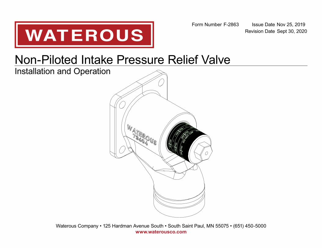
Non-Piloted Intake Pressure Relief ValveInstallation and Operation
Form Number F-2863 Issue Date Nov 25, 2019Revision Date Sept 30, 2020
Waterous Company • 125 Hardman Avenue South • South Saint Paul, MN 55075 • (651) 450-5000www.waterousco.comwww.waterousco.com

Table of ContentsSafety 4
Safety Precautions 4Safety Notices 4
Introduction 6Using this Document 6
Viewing the Document Electronically 6Printing the Document 6
Product Overview 7Non-Piloted Intake Pressure Relief Valve Components 7
Installation 8Installation Overview 8Preparing for the Installation 8Modifying the Equipment 8Determining the Discharge Location 8Dimensions—Factory Installed 9Dimensions—Separately Mounted 10Installing the Separately Mounted Valve 11
Operation 13Maximum Flow Rate Chart—50 to 250 PSI 13Maximum Flow Rate Chart—250 PSI 14Adjusting the Valve 15Maintaining the Valve 16Preventing Valve Damage 16
Maintenance 17Replacing the Valve Seal 17
Service Parts 19Valve Components—Factory Installed 19Valve Components—Separately Mounted 21
Safety Introduction Product Overview Installation Operation Maintenance Service Parts
4 | 23
Safety Precautions• Read and understand all the associated documentation before you begin the
installation.• Read and understand all the notices and safety precautions.• Be aware that these instructions are only guidelines and are not meant to be
definitive. Contact Waterous when you have questions about installing, operating, or maintaining the equipment.
• Do not install the equipment if you are not familiar with the tools and skills needed to safely perform the required procedures—proper installation is the responsibility of the purchaser.
• Do not operate the equipment when safety guards are removed.• Do not modify the equipment.• Regularly check for leaks, worn, or deteriorated parts.
Safety Notices
Purge all pressure beforeservicing.
Liquid ejected at highpressure can cause serious injury.
High Pressure•
•
Direct discharge awayfrom people and equipment.
Discharge ejected at highpressure can cause serious injury and damage.
High Pressure•
•
NOTICEBefore Operation
• Read and understand all the instructions provided.• Check all fluid levels and replenish if necessary.• Remove all shipping plugs and install the operation plugs or caps.
Safety Introduction Product Overview Installation Operation Maintenance Service Parts
5 | 23
Safety Notices—Continued
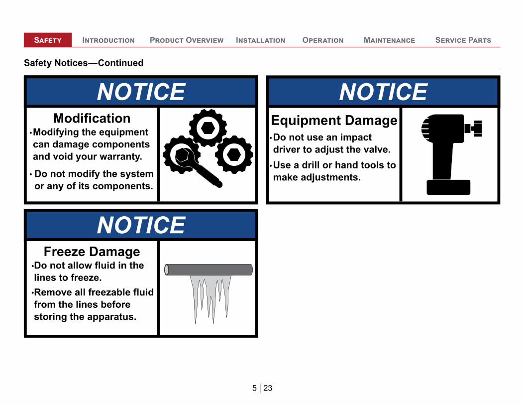
NOTICEModifying the equipmentcan damage componentsand void your warranty.
•
Do not modify the systemor any of its components.
•
Modification
NOTICEDo not allow fluid in thelines to freeze.•
Remove all freezable fluidfrom the lines beforestoring the apparatus.
•
Freeze Damage
NOTICE
Use a drill or hand tools tomake adjustments.
Do not use an impact driver to adjust the valve.
Equipment Damage•
•
6 | 23
Safety Introduction Product Overview Installation Operation Maintenance Service Parts
Use this document to install and operate your Waterous equipment. Understand the following conditions before continuing with the document:• The instructions may refer to options or equipment that you may not have
purchased with your system.• The illustrations in this document are intended to convey concepts. Do not
use the illustrations to determine physical attributes, placement, or proportion.
• Any equipment described in this document is intended to be installed by a person or persons with the necessary skills and knowledge to perform the installation.
• Any equipment described in this document is intended to be operated by a person or persons with the basic knowledge of operating similar equipment.
This document is divided into the following sections:
SafetyThis section describes general precautions and alert symbols that are in this document.
IntroductionThis section is an overview of the document.
Product OverviewThis section describes the components that make-up the system.
InstallationThis section describes the installation and initial setup procedures.
OperationThis section describes the equipment operation.
MaintenanceThis section describes the maintenance procedures.
Service PartsThis section describes the service parts.
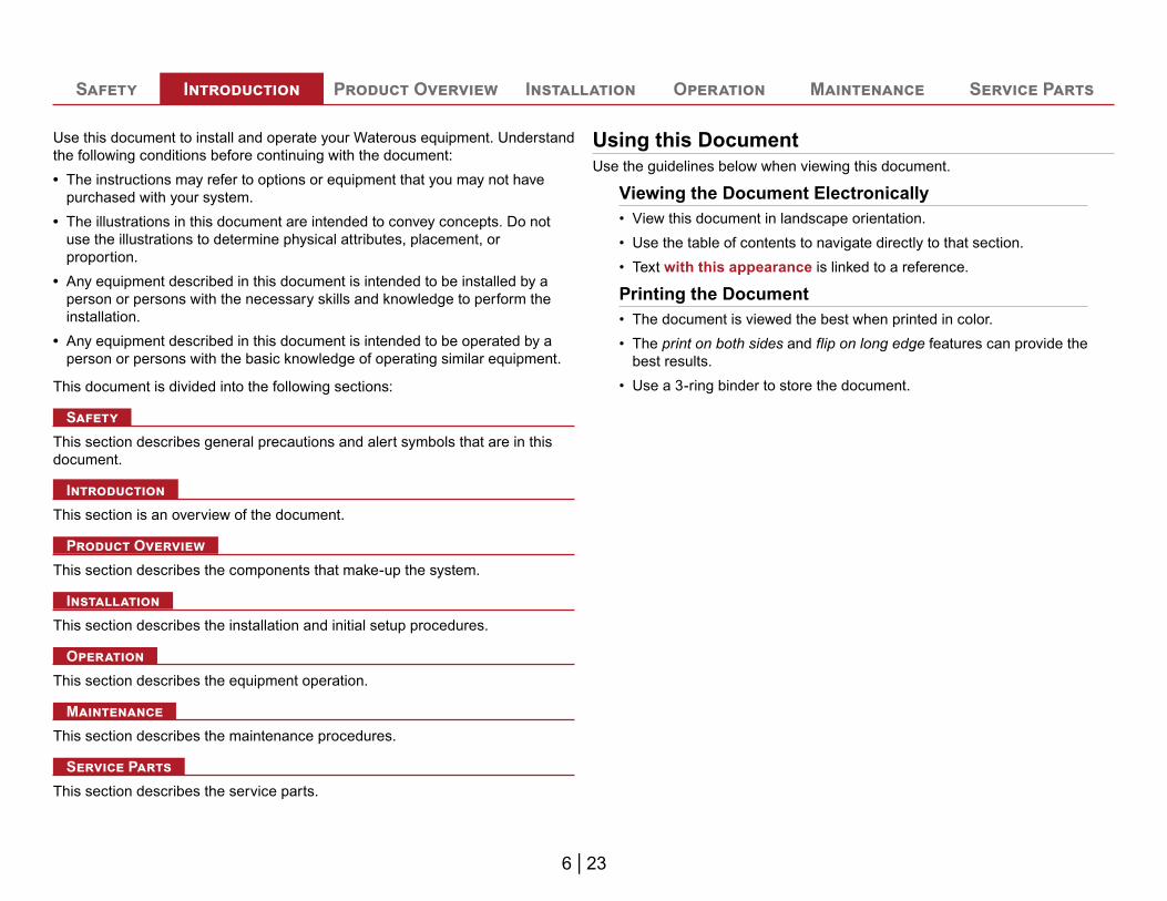
Using this DocumentUse the guidelines below when viewing this document.
Viewing the Document Electronically• View this document in landscape orientation.• Use the table of contents to navigate directly to that section.• Text with this appearance is linked to a reference.
Printing the Document• The document is viewed the best when printed in color.• The print on both sides and flip on long edge features can provide the
best results.• Use a 3-ring binder to store the document.
7 | 23
Safety Introduction Product Overview Installation Operation Maintenance Service Parts
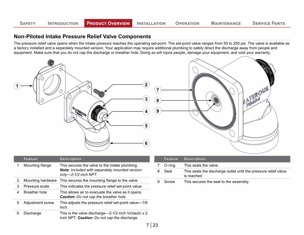
Non-Piloted Intake Pressure Relief Valve ComponentsThe pressure relief valve opens when the intake pressure reaches the operating set-point. The set-point value ranges from 50 to 250 psi. The valve is available as a factory installed and a separately mounted version. Your application may require additional plumbing to safely direct the discharge away from people and equipment. Make sure that you do not cap the discharge or breather hole. Doing so will injure people, damage your equipment, and void your warranty.
1
5
6
2
3
4
FeatureFeature DescriptionDescription1 Mounting flange This secures the valve to the intake plumbing.
Note: Included with separately mounted version only—2-1/2 inch NPT.
2 Mounting hardware This secures the mounting flange to the valve.3 Pressure scale This indicates the pressure relief set-point value.4 Breather hole This allows air to evacuate the valve as it opens.
Caution: Do not cap the breather hole.5 Adjustment screw This adjusts the pressure relief set-point value—7/8
inch.6 Discharge This is the valve discharge—2-1/2 inch Victaulic x 2
inch NPT. Caution: Do not cap the discharge.
7
8
9
FeatureFeature DescriptionDescription7 O-ring This seals the valve.8 Seal This seals the discharge outlet until the pressure relief value
is reached.9 Screw This secures the seal to the assembly.
8 | 23
Safety Introduction Product Overview Installation Operation Maintenance Service Parts
Installation OverviewThe non-piloted intake pressure relief valve is typically installed at the factory. However, you can install the separately-mounted version to an existing application. This equipment is intended to be installed by a person or persons with the basic knowledge of installing similar equipment. Contact Waterous with questions about installing the equipment.
Preparing for the InstallationRead and understand all the installation instructions before installing the equipment. Prepare a suitable, well-lit area, and gather all the necessary tools before you begin the installation.
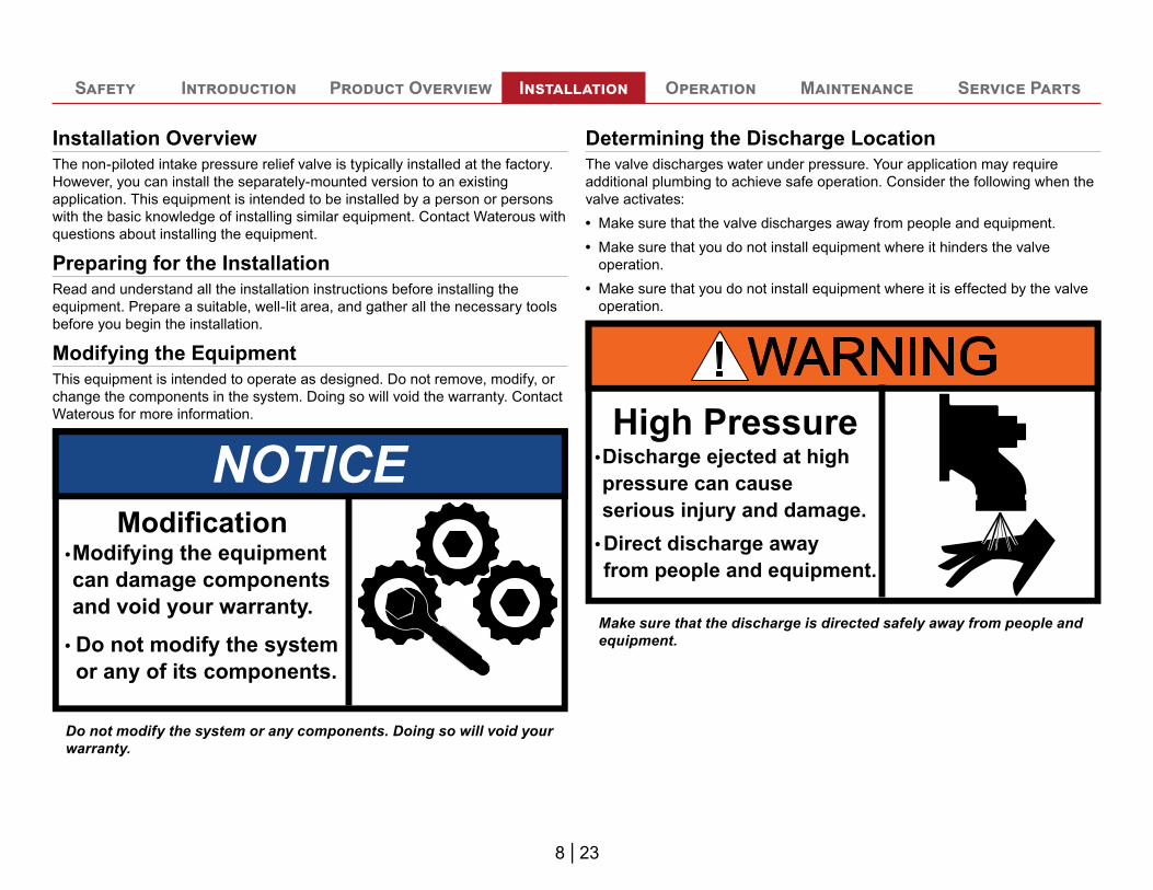
Modifying the EquipmentThis equipment is intended to operate as designed. Do not remove, modify, or change the components in the system. Doing so will void the warranty. Contact Waterous for more information.
NOTICEModifying the equipmentcan damage componentsand void your warranty.
•
Do not modify the systemor any of its components.
•
Modification
Do not modify the system or any components. Doing so will void your warranty.
Determining the Discharge LocationThe valve discharges water under pressure. Your application may require additional plumbing to achieve safe operation. Consider the following when the valve activates:• Make sure that the valve discharges away from people and equipment. • Make sure that you do not install equipment where it hinders the valve
operation.• Make sure that you do not install equipment where it is effected by the valve
operation.
Direct discharge awayfrom people and equipment.
Discharge ejected at highpressure can cause serious injury and damage.
High Pressure•
•
Make sure that the discharge is directed safely away from people and equipment.
9 | 23
Safety Introduction Product Overview Installation Operation Maintenance Service Parts
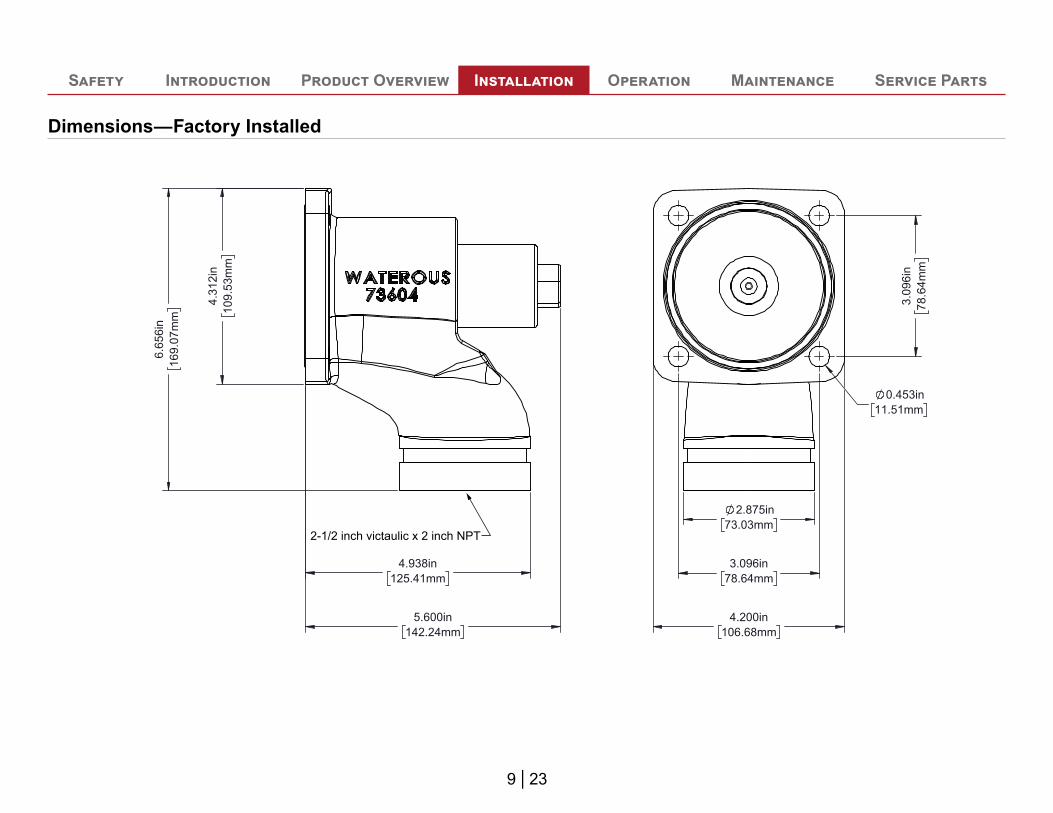
Dimensions—Factory Installed6.
656i
n16
9.07
mm
4.31
2in
109.
53m
m
4.938in125.41mm
5.600in142.24mm
0.453in11.51mm
3.09
6in
78.6
4mm
3.096in78.64mm
2.875in73.03mm
4.200in106.68mm
2-1/2 inch victaulic x 2 inch NPT
10 | 23
Safety Introduction Product Overview Installation Operation Maintenance Service Parts
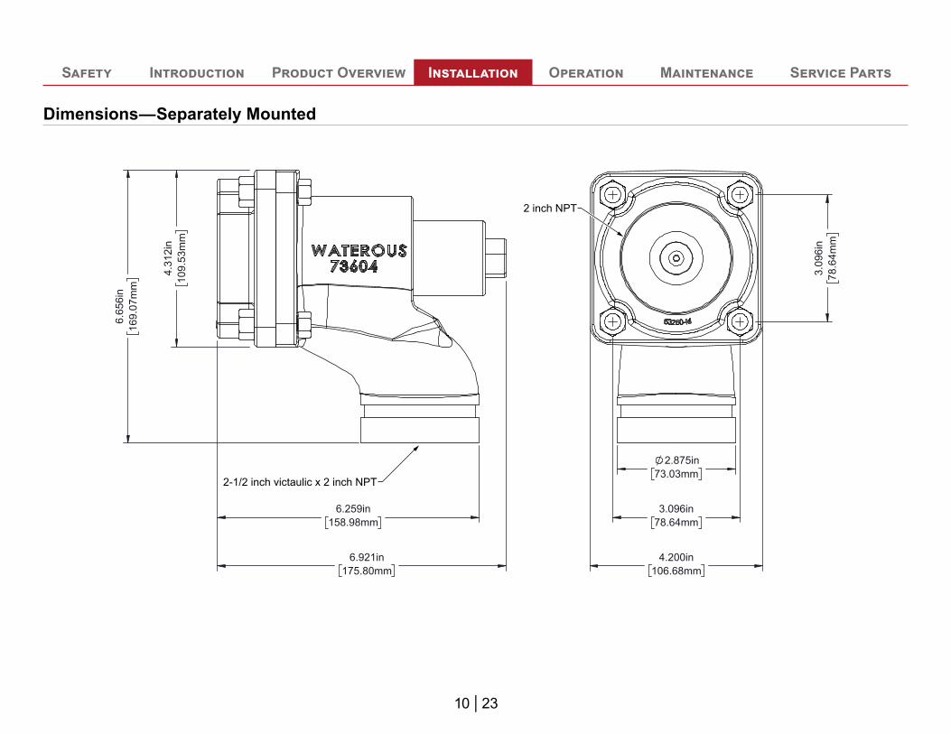
Dimensions—Separately Mounted6.
656i
n16
9.07
mm
4.31
2in
109.
53m
m
6.259in158.98mm
6.921in175.80mm
2-1/2 inch victaulic x 2 inch NPT
2 inch NPT
3.096in78.64mm
2.875in73.03mm
4.200in106.68mm
3.09
6in
78.6
4mm
11 | 23
Safety Introduction Product Overview Installation Operation Maintenance Service Parts
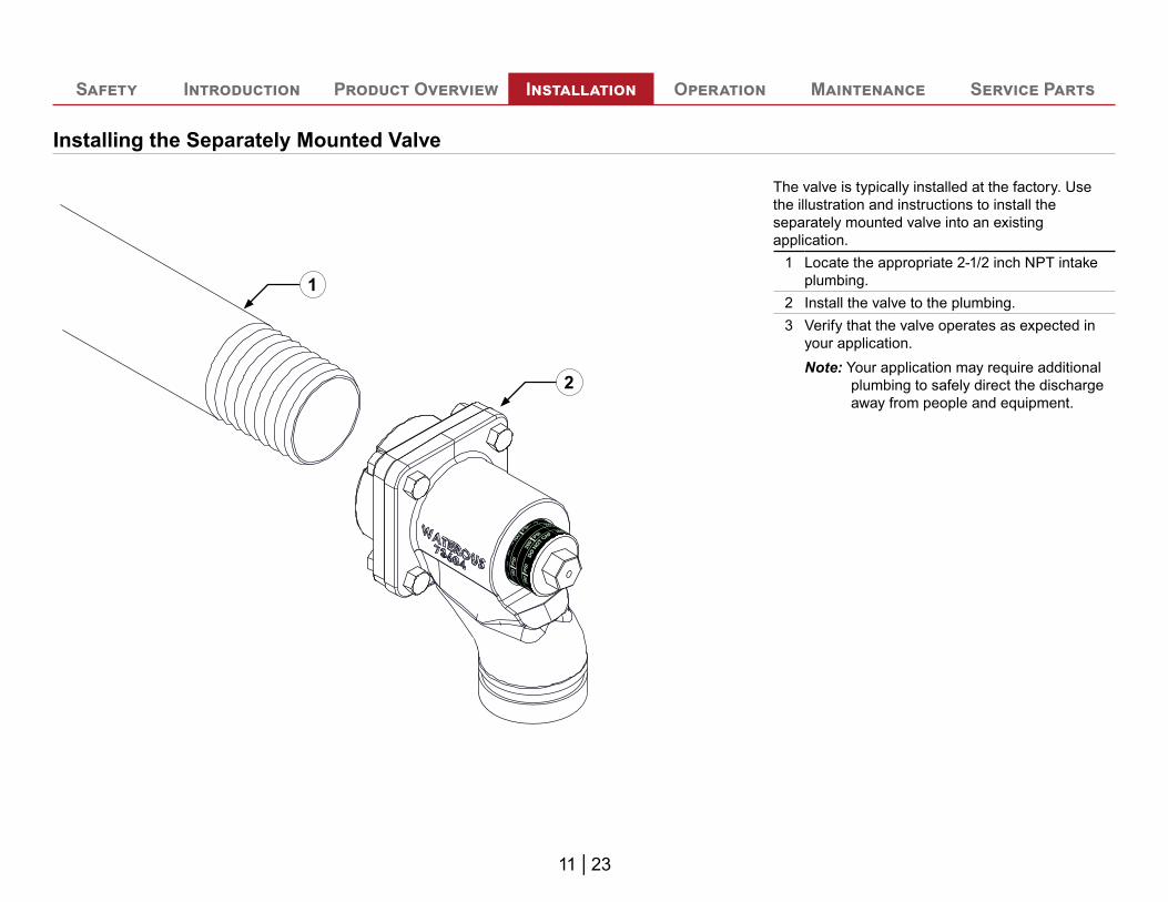
Installing the Separately Mounted Valve
1
2
The valve is typically installed at the factory. Use the illustration and instructions to install the separately mounted valve into an existing application.
1 Locate the appropriate 2-1/2 inch NPT intake plumbing.
2 Install the valve to the plumbing.3 Verify that the valve operates as expected in
your application.Note: Your application may require additional
plumbing to safely direct the discharge away from people and equipment.

Notes
13 | 23
Safety Introduction Product Overview Installation Operation Maintenance Service Parts
0
50
100
150
200
250
300
350
400
450
500
50 100 150 200 250 300 350 400
Inta
ke P
ress
ure,
psi
Maximum Flow Rate through Valve, gpm
Maximum Flow Rate, 50-200 psi
Full open with 50 psi setpoint
Full open with 100 psi setpoint
Full open with 150 psi setpoint
Full open with 200 psi setpoint
Maximum Flow Rate Chart—50 to 250 PSI
14 | 23
Safety Introduction Product Overview Installation Operation Maintenance Service Parts
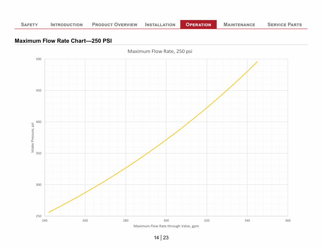
250
300
350
400
450
500
240 260 280 300 320 340 360
Inta
ke P
ress
ure,
psi
Maximum Flow Rate through Valve, gpm
Maximum Flow Rate, 250 psi
Maximum Flow Rate Chart—250 PSI
15 | 23
Safety Introduction Product Overview Installation Operation Maintenance Service Parts
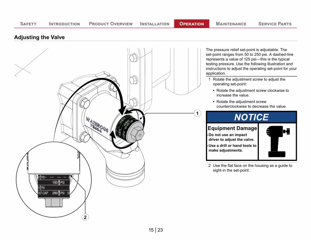
Adjusting the Valve
1
2
The pressure relief set-point is adjustable. The set-point ranges from 50 to 250 psi. A dashed-line represents a value of 125 psi—this is the typical testing pressure. Use the following illustration and instructions to adjust the operating set-point for your application.
1 Rotate the adjustment screw to adjust the operating set-point:• Rotate the adjustment screw clockwise to
increase the value.• Rotate the adjustment screw
counterclockwise to decrease the value.
NOTICE
Use a drill or hand tools tomake adjustments.
Do not use an impact driver to adjust the valve.
Equipment Damage•
•
2 Use the flat face on the housing as a guide to sight-in the set-point.
Safety Introduction Product Overview Installation Operation Maintenance Service Parts
16 | 23
Maintaining the ValveThe valve does not require scheduled maintenance. However, you should regularly inspect the valve for corrosion or damage. You should also include the valve in your quarterly equipment test.
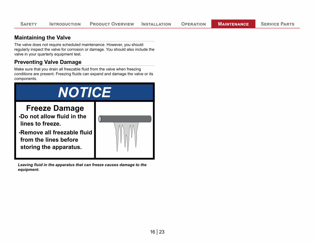
Preventing Valve DamageMake sure that you drain all freezable fluid from the valve when freezing conditions are present. Freezing fluids can expand and damage the valve or its components.
NOTICEDo not allow fluid in thelines to freeze.•
Remove all freezable fluidfrom the lines beforestoring the apparatus.
•
Freeze Damage
Leaving fluid in the apparatus that can freeze causes damage to the equipment.
Safety Introduction Product Overview Installation Operation Maintenance Service Parts
17 | 23
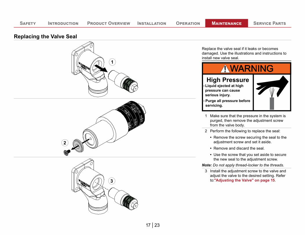
Replacing the Valve Seal
1
2
3
Replace the valve seal if it leaks or becomes damaged. Use the illustrations and instructions to install new valve seal.
Purge all pressure beforeservicing.
Liquid ejected at highpressure can cause serious injury.
High Pressure•
•
1 Make sure that the pressure in the system is purged, then remove the adjustment screw from the valve body.
2 Perform the following to replace the seal:• Remove the screw securing the seal to the
adjustment screw and set it aside.• Remove and discard the seal.• Use the screw that you set aside to secure
the new seal to the adjustment screw.Note: Do not apply thread-locker to the threads.
3 Install the adjustment screw to the valve and adjust the valve to the desired setting. Refer to:"Adjusting the Valve" on page 15.

Notes
19 | 23
Safety Introduction Product Overview Installation Operation Maintenance Service Parts
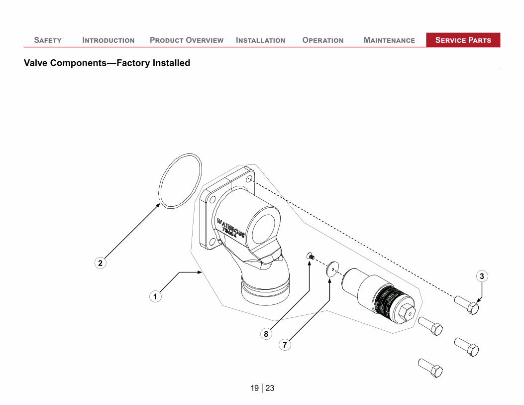
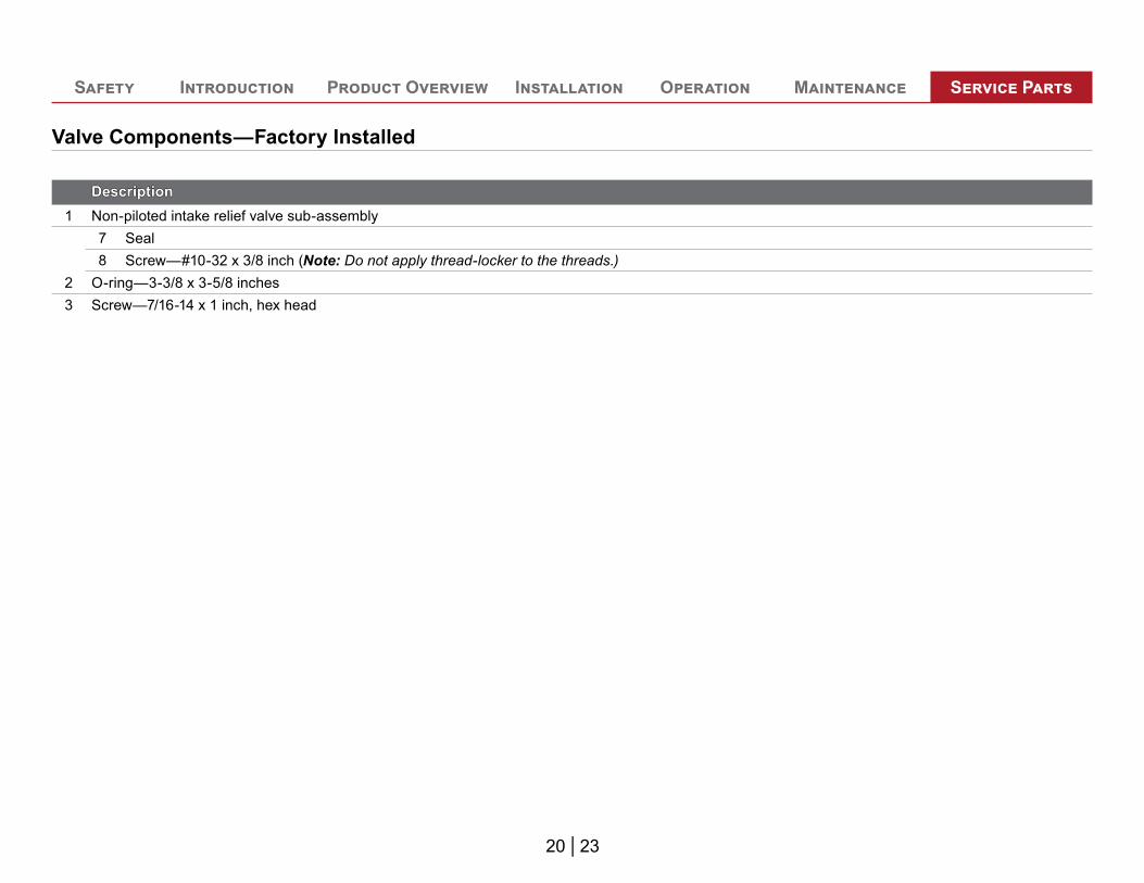
Valve Components—Factory Installed
32
78
1
20 | 23
Safety Introduction Product Overview Installation Operation Maintenance Service Parts
Valve Components—Factory Installed
DescriptionDescription1 Non-piloted intake relief valve sub-assembly
7 Seal8 Screw—#10-32 x 3/8 inch (Note: Do not apply thread-locker to the threads.)
2 O-ring—3-3/8 x 3-5/8 inches3 Screw—7/16-14 x 1 inch, hex head
21 | 23
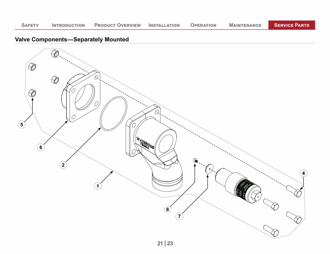
Safety Introduction Product Overview Installation Operation Maintenance Service Parts
Valve Components—Separately Mounted
4
5
6
2
78
1
22 | 23
Safety Introduction Product Overview Installation Operation Maintenance Service Parts
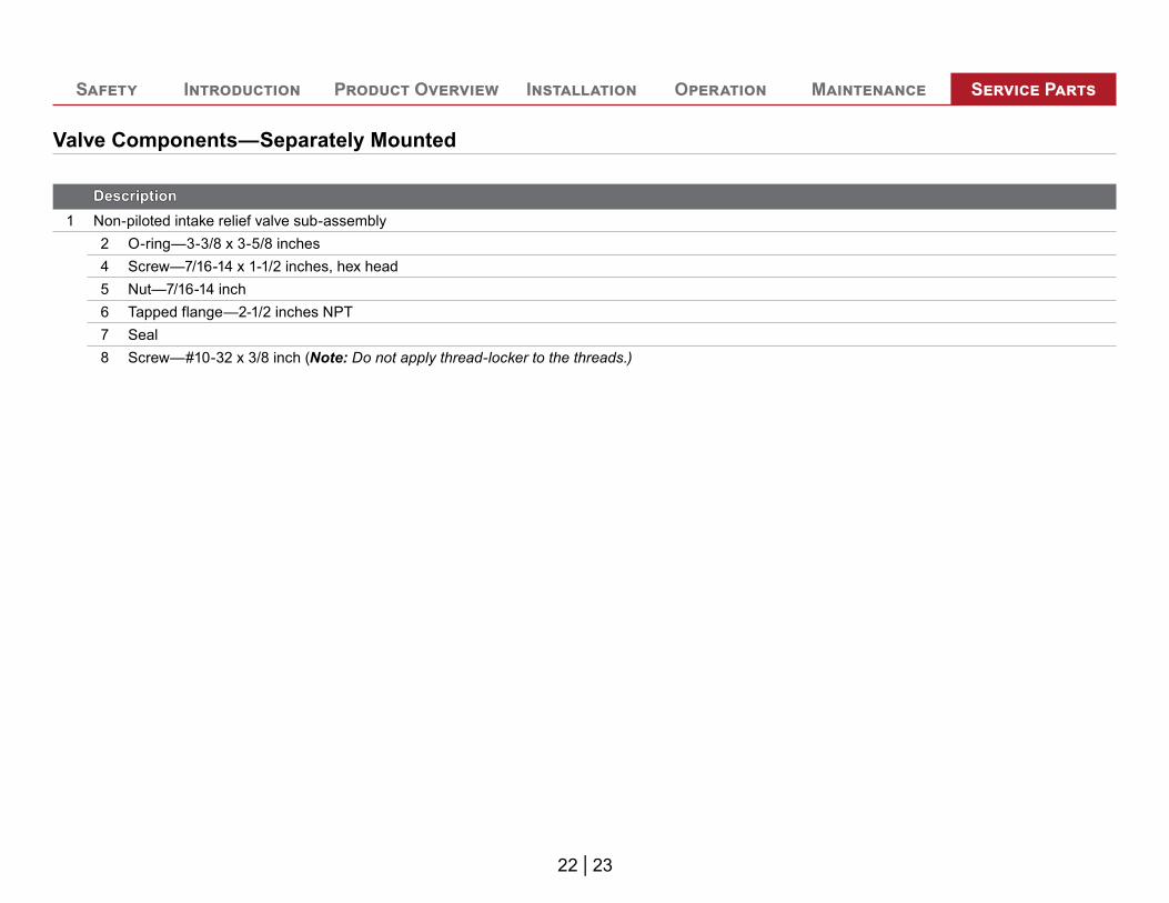
Valve Components—Separately Mounted
DescriptionDescription1 Non-piloted intake relief valve sub-assembly
2 O-ring—3-3/8 x 3-5/8 inches4 Screw—7/16-14 x 1-1/2 inches, hex head5 Nut—7/16-14 inch6 Tapped flange—2-1/2 inches NPT7 Seal8 Screw—#10-32 x 3/8 inch (Note: Do not apply thread-locker to the threads.)

Waterous Company125 Hardman Avenue SouthSouth Saint Paul, MN 55075
(651) 450-5000www.waterousco.comwww.waterousco.com