non-local patch-based image inpainting - ipol journal patch-based image inpainting 2.1 notation the...
TRANSCRIPT
Published in Image Processing On Line on 2017–12–13.Submitted on 2016–09–09, accepted on 2017–09–15.ISSN 2105–1232 c© 2017 IPOL & the authors CC–BY–NC–SAThis article is available online with supplementary materials,software, datasets and online demo athttps://doi.org/10.5201/ipol.2017.189
2015/06/16
v0.5.1
IPOL
article
class
Non-Local Patch-Based Image Inpainting
Alasdair Newson1, Andres Almansa2, Yann Gousseau2, Patrick Perez3
1 Universite Paris Descartes ([email protected])2 Telecom ParisTech, CNRS LTCI (almansa,[email protected])
3 Technicolor ([email protected])
Abstract
Image inpainting is the process of filling in missing regions in an image in a plausible way. Inthis contribution, we propose and describe an implementation of a patch-based image inpaintingalgorithm. The method is actually a two-dimensional version of our video inpainting algorithmproposed in [A. Newson et al., Video inpainting of complex scenes, SIAM Journal of ImagingSciences, 7 (2014)]. The algorithm attempts to minimize a highly non-convex functional, firstintroducted by Wexler et al. in [Wexler et al., Space-time video completion, CCVPR (2004)].The functional specifies that a good solution to the inpainting problem should be an imagewhere each patch is very similar to its nearest neighbor in the unoccluded area. Iterations areperformed in a multi-scale framework which yields globally coherent results. In this manner twoof the major goals of image inpainting, the correct reconstruction of textures and structures,are addressed. We address a series of important practical issues which arise when using suchan approach. In particular, we reduce execution times by using the PatchMatch [C. Barnes,PatchMatch: a randomized correspondence algorithm for structural image editing, ACM Trans-actions on Graphics, (2009)] algorithm for nearest neighbor searches, and we propose a modifiedpatch distance which improves the comparison of textured patches. We address the crucial is-sue of initialization and the choice of the number of pyramid levels, two points which are rarelydiscussed in such approaches. We provide several examples which illustrate the advantages ofour algorithm, and compare our results with those of state-of-the-art methods.
Source Code
The reviewed source code and documentation for this algorithm are available from the web pageof this article1.
Keywords: Image inpainting; variational methods; patch-based
1https://doi.org/10.5201/ipol.2017.189
Alasdair Newson, Andres Almansa, Yann Gousseau, Patrick Perez, Non-Local Patch-Based Image Inpainting, Image Processing OnLine, 7 (2017), pp. 373–385. https://doi.org/10.5201/ipol.2017.189
Alasdair Newson, Andres Almansa, Yann Gousseau, Patrick Perez
1 Introduction
Image inpainting is the task of filling in an unknown region in an image. This is useful, for example,if an area is damaged, or if one wishes to remove an unwanted object from the image. Inpaintingcan be used for personal purposes or for professional image restoration. Two of the main goals ofimage inpainting are the convincing restitution of structures and textures which are coherent withthe unoccluded part of the image.
The first approaches to image inpainting took the form of the minimization of a functional [2, 4,15], whose argument is the image to inpaint. The main goal of such approaches was to continue visualstructures (such as edges) from one point on the occlusion boundary to another. While this producesgood results for smooth images, they fail at reproducing textured content. Several algorithms whichcould maintain both structure and texture in an inpainting result were subsequently proposed [5, 6, 7].These algorithms all hinged on the notion of image patches (small square neighborhoods), which werefirst introduced by Efros and Leung [8] for texture synthesis.
The next step forward in inpainting was to reformulate these patch-based approaches (whichwere, for the most part, greedy methods) in a more rigorous minimization framework. This was firstdone using discrete minimization [12, 18], and then in a continuous context by Arias et al. [1, 9].One important element of such methods is that they use a multi-scale approach to converge to betterinpainting solutions. To the authors’ knowledge, this class of algorithms (multiscale minimization ofa patch-based energy) produces the best inpainting results to date.
In this paper, we take a similar approach. We minimize a patch-based functional taken from thevideo inpainting [19, 20] and texture synthesis [13] literature. Although the core of our algorithm issimilar to that of Arias et al., [9] there are several important differences, which we list here. Firstly,we identify an important problem concerning the correct inpainting of textures with patch-basedmethods, and modify the patch distance to address this problem, in a similar manner to that ofLiu and Caselles [14] in image inpainting and Newson et al. [17] in video inpainting. Secondly, weprovide specific details concerning the influential initialization. Thirdly, we provide a theoreticallymotivated approach to setting the number of levels automatically in the multi-scale approach. Thisparameter has extremely important consequences on the quality of the inpainting results, and israrely discussed in other approaches. Finally, as proposed in our previous work [17], we use thePatchMatch algorithm [3] to provide a crucial speedup for a nearest neighbor search, although thisapproach has also been taken by Arias et al.
A pseudo-code for our algorithm may be seen in Algorithm 2. To summarise, this work describesan image inpainting algorithm similar in its approach to our previous work on video inpainting [17].In order to adhere to the execution time standard of IPOL (30s or less), we have restricted thescope of this work to the case of images. The algorithm produces high-quality results in the imagecase, and is shown to be as useful as in the cases of videos. The algorithm may be tested with theaccompanying online demo as well as with the provided C++ code.
This publication accompanies our previous publication on video inpainting [17], which applies thesame algorithm as presented here to videos. The corresponding video results and code (written inMatlab) can be accessed at the following website: http://www.telecom-paristech.fr/~gousseau/video_inpainting.
2 Proposed Algorithm
As discussed above, the core of our algorithm is the minimization of a patch-based non-local func-tional. Before describing the algorithm in detail, first of all we need to set out some notation.
374
Non-Local Patch-Based Image Inpainting
2.1 Notation
The image support is denoted with Ω, and this support is separated into two regions: H the occlusion(H for “hole”) and D the unoccluded region (D for “data set”), such that H∩D = ∅ and H∪D = Ω.A position in the support may be denoted with p = (x, y). The image content itself is denoted withu : Ω→ R3.
Another very important notion is that of a patch. We first define the patch neighborhood of apixel p as a set of positions in Ω, denoted with Np, of cardinality N . The patch itself is denoted withWp = (u(x1), · · · , u(xN)). A connected notion which we need to define is that of a nearest neighbor(NN for short) of a patch Wp. The NN of Wp is a patch Wq in another set of patches which minimizesa certain patch distance d(Wp,Wq). We shall choose NNs from the set of patches which contain nooccluded pixels. For this, define D the set of positions such that ∀p ∈ D,Np ⊂ D. Therefore, theNN of Wp is Wq, with q = argmin
k∈Dd2(Wp,Wk). Similarly, we define H, the“dilated” occlusion, which
is just the complement of D in Ω.Finally, we define the shift map φ : Ω → N2 as a vector field which shows where the NN of a
patch is located. That is, the NN of Wp is Wp+φ(p).
2.2 Variational Framework
The functional which we wish to minimize takes the following form
E(u, φ) =∑p∈H
d2(Wp,Wp+φ(p)). (1)
Intuitively speaking, this highly non-convex functional specifies that for a “good” solution, eachpatch inside H should be as similar as possible (in terms of the patch distance d2(·, ·)) to its nearestneighbor in the unoccluded region D. We use the following distance
d2(Wp,Wp+φ(p)) =∑q∈Np
(u(q)− u(q + φ(p)))2. (2)
Following the heuristic proposed in [20], a solution is obtained using an iterated alternatingminimization, as well as a multi-scale framework. At each scale, we minimize firstly with respect tothe shift map φ, then with respect to the image content u. These two steps correspond, respectively,to the following operations:
• nearest neighbor search;
• image reconstruction.
The nearest neighbor search can be quite expensive, especially if the whole image is used as thesearch space. In Section 3.1, we specify the manner in which the NN search is carried out, and howthe computational issue is addressed. The reconstruction process is described in Section 3.2. Animprovement of this basic process is proposed in Section 3.3 in order to improve the reconstructionof textures. Section 3.4 deals with the initialization step, and Section 3.5 deals with the multi-scaleframework of the algorithm, both points being especially important given the non-convex nature ofthe problem.
3 Algorithm
Now that we have given a broad outline of our approach, we provide the specific algorithmic detailsnecessary for the implementation of each component of our algorithm.
375
Alasdair Newson, Andres Almansa, Yann Gousseau, Patrick Perez
3.1 Approximate Nearest neighbor Search
As mentioned previously, the NN search can be quite computationally expensive. In such situations,it is common to use approximate nearest neighbors (ANN) instead of exact nearest neighbors. In thisimplementation, we use the PatchMatch algorithm to search for nearest neighbors. This algorithmwas introduced by Barnes et al. [3] and relies on the idea that good shift maps tend to be piecewiseconstant. In other words, a relative shift which leads to a good NN for a patch Wp has a good chanceof leading to a good NN for the patches situated around Wp.
The algorithm consists of three steps:
• random initialization;
• propagation;
• random search.
The first step is carried out once at the beginning of the algorithm. Each occluded pixel israndomly assigned a candidate NN in the region D. The next two steps are carried out on each patch,and each patch is visited in lexicographical order on even iterations and in inverse lexicographicalorder on odd iterations (see [3] for details). This is carried out a predefined number of times. Thepropagation step attempts to spread good shifts throughout the vector field φ. Finally, the randomsearch step looks for better NNs randomly in an increasingly small window around the currentNN. Since PatchMatch itself is not a novelty of our algorithm, we refer the reader to the originalpublication [3] for further details.
In practice, we only need the initialization step during the filling in of the occlusion (at thebeginning of our algorithm). After this, we may consider that we have a good initialization of φ, whichis simply the φ of the previous iteration. Let us emphasize that PatchMatch has already been used asa way to accelerate the search for ANN in a commercial implementation of the algorithm from [20], inthe content aware tool from the software Photoshop. The pseudo-code for the PatchMatch algorithmmay be seen in Algorithm 1.
3.2 Reconstructing the Image
The second step in the iterative algorithm is the minimization of the functional in Equation (1) withrespect to u. Intuitively speaking, this is the process of assigning a color value to each position inthe occluded area, or as we refer to it here, the reconstruction process. The minimization of (1) withrespect to u should lead to each pixel being reconstructed with an unweighted mean of several colorvalues in D. However, we shall use a weighted mean scheme, initially proposed by Wexler et al. [20].Experimentally, we have observed that this improves the convergence of the algorithm.
Given a shift map, each pixel is reconstructed as:
u(p) =
∑q∈Np
spqu(p+ φ(q))∑q∈Np
spq, (3)
where spq is the weight assigned to the pixel value for p indicated by the ANN of Wq,
spq = exp
(−d2(Wq,Wq+φ(q))
2σ2
), (4)
where σ is set to the 75th percentile of all the current patch distances, as is done by Wexler et al. [20].Informally, it can be seen that each pixel p is reconstructed using the “versions” of p indicated
by the ANNs of all the patches which contain p. This operation is carried out for all pixels p ∈ D.
376
Non-Local Patch-Based Image Inpainting
Algorithm 1: ANN search with PatchMatch.
Data: Current inpainting configuration u (height: m, width: n), φ, HParameters: rmax (max(m,n)), ρ (0.5)Result: ANN shift map φ
for k = 1 to kmax do
for i = 1 to |H| doif k even then /* Propagation on even iteration (lexicographical order) */
p = pi;a = p− (1, 0), b = p− (0, 1);q = arg minr∈p,a,b d(W u
p ,Wup+φ(r));
if p+ φ(q) ∈ D then φ(p)← φ(q)else /* Propagation on odd iteration (inverted order) */
p = p|H|−i+1;
a = p+ (1, 0), b = p+ (0, 1);q = arg minr∈p,a,b d(W u
p ,Wup+φ(r));
if p+ φ(q) ∈ D then φ(p)← φ(q)end
zmax ← d− log(max(m,n))log(ρ)
e;for z = 1 to zmax do
q = p+ φ(p) + brmaxρzRandUniform([−1, 1]2) c;
if d(W up ,W
up+φ(q)) < d(W u
p ,Wup+φ(p)) and p+ φ(q) ∈ D then φ(p)← φ(q)
end
end
end
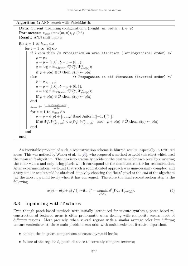
An inevitable problem of such a reconstruction scheme is blurred results, especially in texturedareas. This was noticed by Wexler et al. in [20], who proposed a method to avoid this effect which usedthe mean shift algorithm. The idea is to gradually decide on the best value for each pixel by clusteringthe color values and only using pixels which correspond to the dominant cluster for reconstruction.After experimentation, we found that such a sophisticated approach was unnecessarily complex, anda very similar result could be obtained simply by choosing the “best” pixel at the end of the algorithm(at the finest pyramid level) when it has converged. Therefore the final reconstruction step is thefollowing
u(p) = u(p+ φ(q∗)),with q∗ = argminq∈Np
d2(Wq,Wq+φ(q)). (5)
3.3 Inpainting with Textures
Even though patch-based methods were initially introduced for texture synthesis, patch-based re-construction of textured areas is often problematic when dealing with composite scenes made ofdifferent regions. More precisely, when several regions with a similar average color but differingtexture contents exist, three main problems can arise with multi-scale and iterative algorithms:
• ambiguities in patch comparisons at coarse pyramid levels;
• failure of the regular `2 patch distance to correctly compare textures;
377
Alasdair Newson, Andres Almansa, Yann Gousseau, Patrick Perez
• the weighted mean reconstruction tends to smooth textures during the algorithm, which inturn leads to smooth patches being chosen as NNs.
In order to address these problems, we introduce texture features into the patch distance. Thegoal of these features is to correctly match textured patches with similarly textured patches. Afterexperimenting with several different features, we found that the following features, inspired by thework of Liu and Caselles [14], identified textures in a satisfactory manner for our purposes
Tx(p) =1
card(ν)
∑q∈ν
|Ix(p)|
Ty(p) =1
card(ν)
∑q∈ν
|Iy(p)|,(6)
where ν is a neighborhood centered on p, and Ix and Iy are the derivatives of the image in the xand y directions. In the case of white noise patches with a Gaussian distribution, these attributestend to the variance of the noise (up to a multiplicative factor) as the size of ν increases. Therefore,we consider our texture to be well-represented by the variance of its pixel values. This is obviouslyquite a simple representation of a texture, but we found that it distinguishes well between texturedand non textured areas with the same average color.
Thus, the squared patch distance is now redefined as
d2(Wp,Wq) =1
N
∑r∈Np
(‖u(r)− u(r − p+ q))‖22 + λ‖T (r)− T (r − p+ q)‖22
), (7)
where λ is a weighting scalar to balance the effects of both color and texture information in thepatch distance (the value of this parameter is defined in Section 3.6). It is important to note that wecalculate these features at the finest pyramid level for the unoccluded pixels p ∈ D, and propagatethem to coarser levels by nearest neighbor subsampling. This is necessary since the textures are notpresent at coarser levels, the image having been smoothed and subsampled.
This solves the problem of identifying and matching similarly textured patches, but due to thepatch averaging process in Equation (4), we still have a tendency to smooth the result. This graduallyleads to inpainting with the wrong texture, in spite of the process detailed in Section 3.2. To dealwith this, we create a separate image with the texture features, and this image is inpainted in parallelto the color image.
T (p) =
∑q∈Np
sqpT (p+ φ(q))∑q∈Np
sqp, ∀p ∈ H. (8)
A comparative example of the effect of using these features may be seen in Figure 2. It is clearthat without these features, satisfactory results are difficult to obtain.
3.4 Initialization
All iterative methods which attempt to optimise an objective function require an initial solution,and this initialization turns out to be very important in our case (which is highly non-convex, asmentioned previously). It is also an issue which is seldom discussed in many works on the subject.
We propose an “onion-peel” approach which inpaints the occlusion one layer at a time, erodingthe occlusion progressively. The layers are one-pixel thick, and located at the border of the occlusion.Each pixel in a layer is processed using the information of the inpainting solution of the previous
378
Non-Local Patch-Based Image Inpainting
(a) Occluded inputimage
(b) Randominitialization
(c) Smoothzero-Laplacianinterpolation
(d) Onion peelinitialization
(a) Original image (b) Inpainting afterrandom initialization
(c) Inpainting afterzero Laplacian
(d) Inpainting afteronion peel
initialization
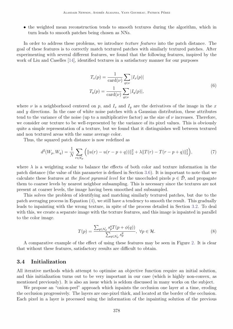
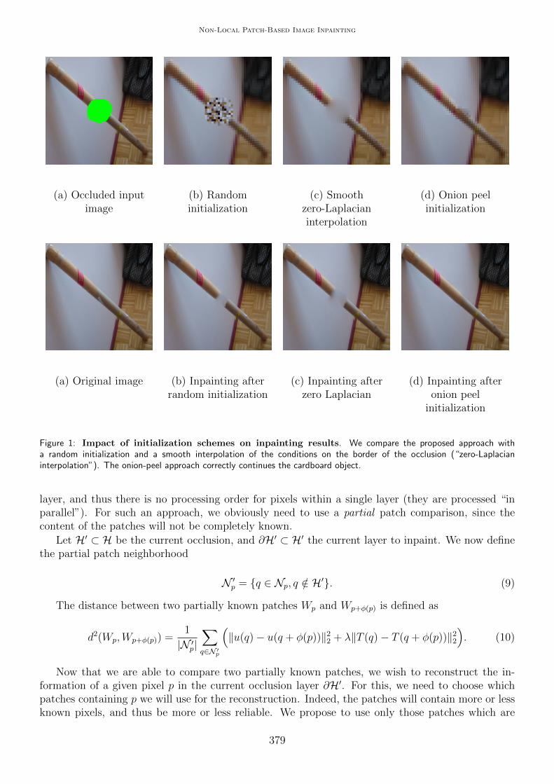
Figure 1: Impact of initialization schemes on inpainting results. We compare the proposed approach witha random initialization and a smooth interpolation of the conditions on the border of the occlusion (“zero-Laplacianinterpolation”). The onion-peel approach correctly continues the cardboard object.
layer, and thus there is no processing order for pixels within a single layer (they are processed “inparallel”). For such an approach, we obviously need to use a partial patch comparison, since thecontent of the patches will not be completely known.
Let H′ ⊂ H be the current occlusion, and ∂H′ ⊂ H′ the current layer to inpaint. We now definethe partial patch neighborhood
N ′p = q ∈ Np, q /∈ H′. (9)
The distance between two partially known patches Wp and Wp+φ(p) is defined as
d2(Wp,Wp+φ(p)) =1
|N ′p|∑q∈N ′
p
(‖u(q)− u(q + φ(p))‖22 + λ‖T (q)− T (q + φ(p))‖22
). (10)
Now that we are able to compare two partially known patches, we wish to reconstruct the in-formation of a given pixel p in the current occlusion layer ∂H′. For this, we need to choose whichpatches containing p we will use for the reconstruction. Indeed, the patches will contain more or lessknown pixels, and thus be more or less reliable. We propose to use only those patches which are
379
Alasdair Newson, Andres Almansa, Yann Gousseau, Patrick Perez
centered at known pixels. Thus, we have
up =
∑q∈N ′
psqpu(p+ φ(q))∑q∈N ′
psqp
. (11)
The texture features are reconstructed in the same fashion. In Figure 1, we compare the results ofour algorithm using different initializations. In this case, as in many of our other experiments, itis clear that the use of an onion peel approach provides the best initialization when compared withother common approaches.
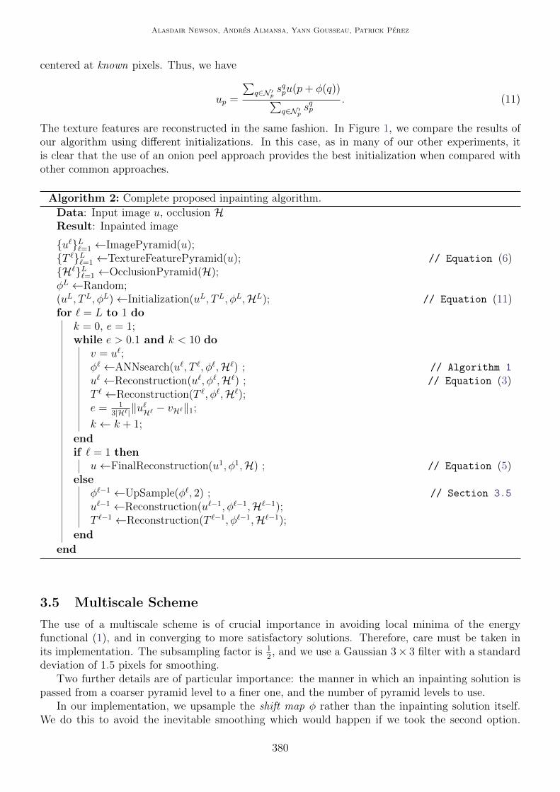
Algorithm 2: Complete proposed inpainting algorithm.
Data: Input image u, occlusion HResult: Inpainted image
u`L`=1 ←ImagePyramid(u);T `L`=1 ←TextureFeaturePyramid(u); // Equation (6)H`L`=1 ←OcclusionPyramid(H);φL ←Random;(uL, TL, φL)←Initialization(uL, TL, φL,HL); // Equation (11)for ` = L to 1 do
k = 0, e = 1;while e > 0.1 and k < 10 do
v = u`;φ` ←ANNsearch(u`, T `, φ`,H`) ; // Algorithm 1
u` ←Reconstruction(u`, φ`,H`) ; // Equation (3)T ` ←Reconstruction(T `, φ`,H`);e = 1
3|H`|‖u`H` − vH`‖1;
k ← k + 1;
endif ` = 1 then
u←FinalReconstruction(u1, φ1,H) ; // Equation (5)else
φ`−1 ←UpSample(φ`, 2) ; // Section 3.5
u`−1 ←Reconstruction(u`−1, φ`−1,H`−1);T `−1 ←Reconstruction(T `−1, φ`−1,H`−1);
end
end
3.5 Multiscale Scheme
The use of a multiscale scheme is of crucial importance in avoiding local minima of the energyfunctional (1), and in converging to more satisfactory solutions. Therefore, care must be taken inits implementation. The subsampling factor is 1
2, and we use a Gaussian 3× 3 filter with a standard
deviation of 1.5 pixels for smoothing.Two further details are of particular importance: the manner in which an inpainting solution is
passed from a coarser pyramid level to a finer one, and the number of pyramid levels to use.In our implementation, we upsample the shift map φ rather than the inpainting solution itself.
We do this to avoid the inevitable smoothing which would happen if we took the second option.
380
Non-Local Patch-Based Image Inpainting
Indeed, the correct textures are not present in the coarser level (as we mentioned in Section 3.3),and therefore using this as an initialization could encourage the algorithm to use smoother areas forinpainting. The shift map is upsampled using a simple nearest neighbors interpolation, with non-integer coordinates resulting from this interpolation being rounded down to the nearest integer. Then,the initial solution is produced by reconstructing the image at the new resolution with Equation (3).The same process is applied to the texture features.
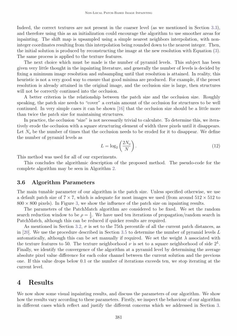
The next choice which must be made is the number of pyramid levels. This subject has beengiven very little thought in the inpainting literature, and generally the number of levels is decided byfixing a minimum image resolution and subsampling until that resolution is attained. In reality, thisheuristic is not a very good way to ensure that good minima are produced. For example, if the presetresolution is already attained in the original image, and the occlusion size is large, then structureswill not be correctly continued into the occlusion.
A better criterion is the relationship between the patch size and the occlusion size. Roughlyspeaking, the patch size needs to “cover” a certain amount of the occlusion for structures to be wellcontinued. In very simple cases it can be shown [16] that the occlusion size should be a little morethan twice the patch size for maintaining structures.
In practice, the occlusion “size” is not necessarily trivial to calculate. To determine this, we itera-tively erode the occlusion with a square structuring element of width three pixels until it disappears.Let No be the number of times that the occlusion needs to be eroded for it to disappear. We definethe number of pyramid levels as
L = log2
(2No
N
). (12)
This method was used for all of our experiments.This concludes the algorithmic description of the proposed method. The pseudo-code for the
complete algorithm may be seen in Algorithm 2.
3.6 Algorithm Parameters
The main tunable parameter of our algorithm is the patch size. Unless specified otherwise, we usea default patch size of 7× 7, which is adequate for most images we used (from around 512× 512 to800× 800 pixels). In Figure 3, we show the influence of the patch size on inpainting results.
The parameters of the PatchMatch algorithm are considered to be fixed. We set the randomsearch reduction window to be ρ = 1
2. We have used ten iterations of propagation/random search in
PatchMatch, although this can be reduced if quicker results are required.As mentioned in Section 3.2, σ is set to the 75th percentile of all the current patch distances, as
in [20]. We use the procedure described in Section 3.5 to determine the number of pyramid levels Lautomatically, although this can be set manually if required. We set the weight λ associated withthe texture features to 50. The texture neighborhood ν is set to a square neighborhood of side 2L.Finally, we identify the convergence of the algorithm at a pyramid level by determining the averageabsolute pixel value difference for each color channel between the current solution and the previousone. If this value drops below 0.1 or the number of iterations exceeds ten, we stop iterating at thecurrent level.
4 Results
We now show some visual inpainting results, and discuss the parameters of our algorithm. We showhow the results vary according to these parameters. Firstly, we inspect the behaviour of our algorithmin different cases which reflect and justify the different concerns which we addressed in Section 3.
381
Alasdair Newson, Andres Almansa, Yann Gousseau, Patrick Perez
In particular, we look at the importance of dealing with textures correctly and the influence of thepatch size on inpainting results. Finally, we compare our results with other commonly used andsuccessful inpainting methods.
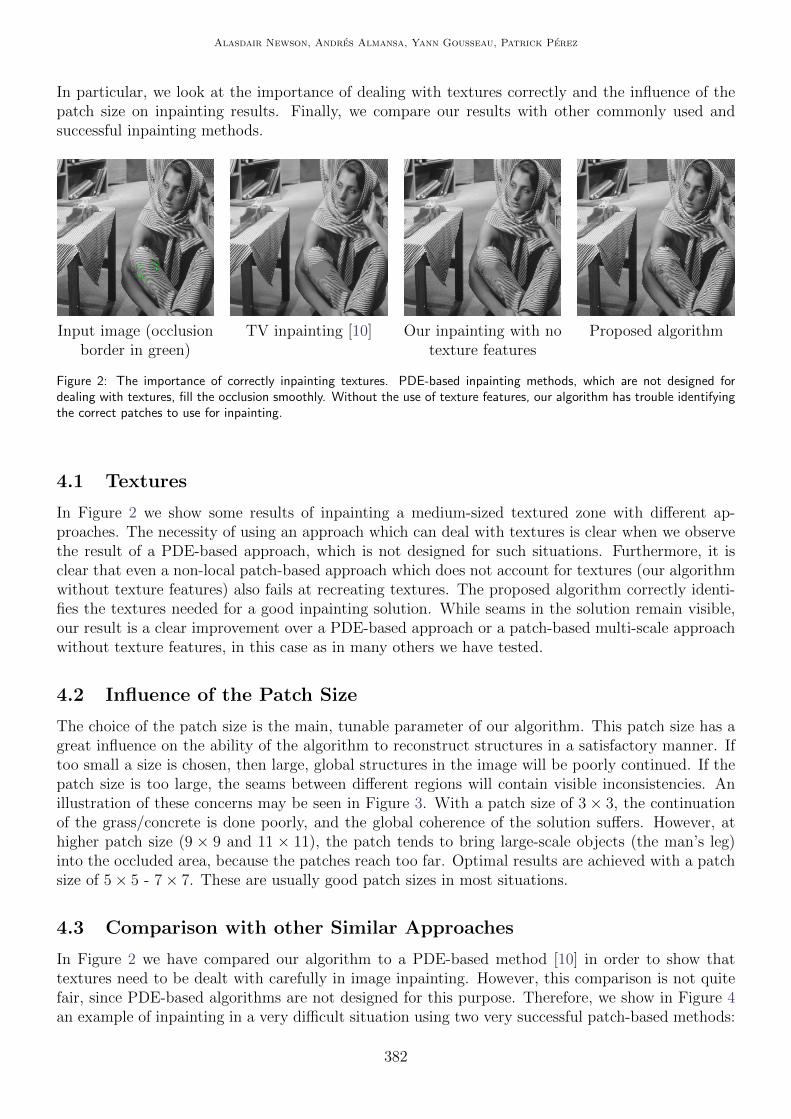
Input image (occlusionborder in green)
TV inpainting [10] Our inpainting with notexture features
Proposed algorithm
Figure 2: The importance of correctly inpainting textures. PDE-based inpainting methods, which are not designed fordealing with textures, fill the occlusion smoothly. Without the use of texture features, our algorithm has trouble identifyingthe correct patches to use for inpainting.
4.1 Textures
In Figure 2 we show some results of inpainting a medium-sized textured zone with different ap-proaches. The necessity of using an approach which can deal with textures is clear when we observethe result of a PDE-based approach, which is not designed for such situations. Furthermore, it isclear that even a non-local patch-based approach which does not account for textures (our algorithmwithout texture features) also fails at recreating textures. The proposed algorithm correctly identi-fies the textures needed for a good inpainting solution. While seams in the solution remain visible,our result is a clear improvement over a PDE-based approach or a patch-based multi-scale approachwithout texture features, in this case as in many others we have tested.
4.2 Influence of the Patch Size
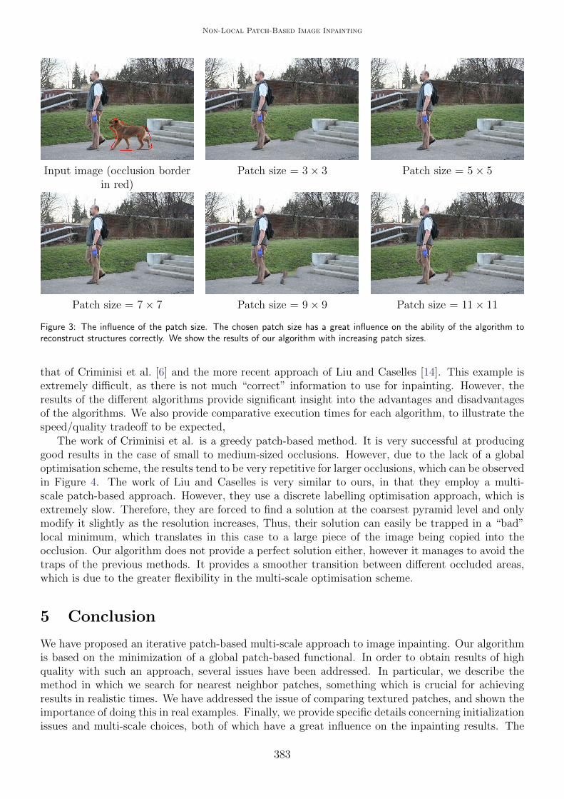
The choice of the patch size is the main, tunable parameter of our algorithm. This patch size has agreat influence on the ability of the algorithm to reconstruct structures in a satisfactory manner. Iftoo small a size is chosen, then large, global structures in the image will be poorly continued. If thepatch size is too large, the seams between different regions will contain visible inconsistencies. Anillustration of these concerns may be seen in Figure 3. With a patch size of 3× 3, the continuationof the grass/concrete is done poorly, and the global coherence of the solution suffers. However, athigher patch size (9 × 9 and 11 × 11), the patch tends to bring large-scale objects (the man’s leg)into the occluded area, because the patches reach too far. Optimal results are achieved with a patchsize of 5× 5 - 7× 7. These are usually good patch sizes in most situations.
4.3 Comparison with other Similar Approaches
In Figure 2 we have compared our algorithm to a PDE-based method [10] in order to show thattextures need to be dealt with carefully in image inpainting. However, this comparison is not quitefair, since PDE-based algorithms are not designed for this purpose. Therefore, we show in Figure 4an example of inpainting in a very difficult situation using two very successful patch-based methods:
382
Non-Local Patch-Based Image Inpainting
Input image (occlusion borderin red)
Patch size = 3× 3 Patch size = 5× 5
Patch size = 7× 7 Patch size = 9× 9 Patch size = 11× 11
Figure 3: The influence of the patch size. The chosen patch size has a great influence on the ability of the algorithm toreconstruct structures correctly. We show the results of our algorithm with increasing patch sizes.
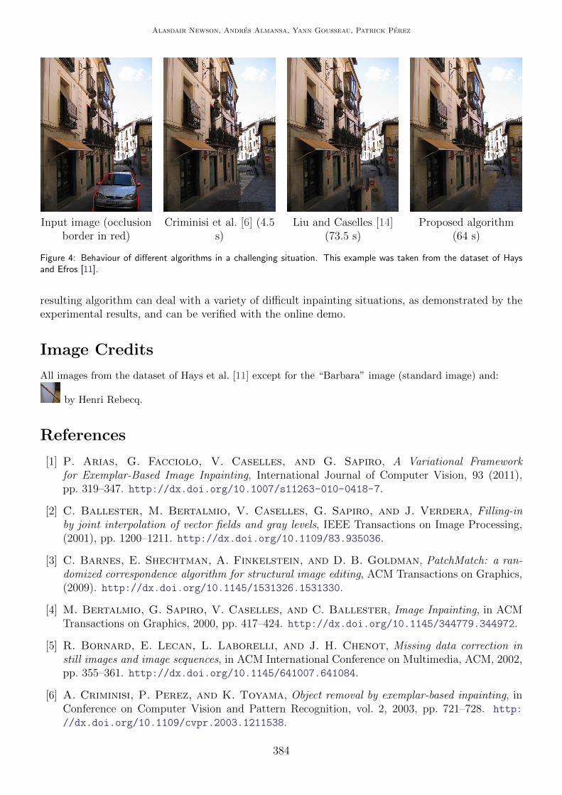
that of Criminisi et al. [6] and the more recent approach of Liu and Caselles [14]. This example isextremely difficult, as there is not much “correct” information to use for inpainting. However, theresults of the different algorithms provide significant insight into the advantages and disadvantagesof the algorithms. We also provide comparative execution times for each algorithm, to illustrate thespeed/quality tradeoff to be expected,
The work of Criminisi et al. is a greedy patch-based method. It is very successful at producinggood results in the case of small to medium-sized occlusions. However, due to the lack of a globaloptimisation scheme, the results tend to be very repetitive for larger occlusions, which can be observedin Figure 4. The work of Liu and Caselles is very similar to ours, in that they employ a multi-scale patch-based approach. However, they use a discrete labelling optimisation approach, which isextremely slow. Therefore, they are forced to find a solution at the coarsest pyramid level and onlymodify it slightly as the resolution increases, Thus, their solution can easily be trapped in a “bad”local minimum, which translates in this case to a large piece of the image being copied into theocclusion. Our algorithm does not provide a perfect solution either, however it manages to avoid thetraps of the previous methods. It provides a smoother transition between different occluded areas,which is due to the greater flexibility in the multi-scale optimisation scheme.
5 Conclusion
We have proposed an iterative patch-based multi-scale approach to image inpainting. Our algorithmis based on the minimization of a global patch-based functional. In order to obtain results of highquality with such an approach, several issues have been addressed. In particular, we describe themethod in which we search for nearest neighbor patches, something which is crucial for achievingresults in realistic times. We have addressed the issue of comparing textured patches, and shown theimportance of doing this in real examples. Finally, we provide specific details concerning initializationissues and multi-scale choices, both of which have a great influence on the inpainting results. The
383
Alasdair Newson, Andres Almansa, Yann Gousseau, Patrick Perez
Input image (occlusionborder in red)
Criminisi et al. [6] (4.5s)
Liu and Caselles [14](73.5 s)
Proposed algorithm(64 s)
Figure 4: Behaviour of different algorithms in a challenging situation. This example was taken from the dataset of Haysand Efros [11].
resulting algorithm can deal with a variety of difficult inpainting situations, as demonstrated by theexperimental results, and can be verified with the online demo.
Image Credits
All images from the dataset of Hays et al. [11] except for the “Barbara” image (standard image) and:
by Henri Rebecq.
References
[1] P. Arias, G. Facciolo, V. Caselles, and G. Sapiro, A Variational Frameworkfor Exemplar-Based Image Inpainting, International Journal of Computer Vision, 93 (2011),pp. 319–347. http://dx.doi.org/10.1007/s11263-010-0418-7.
[2] C. Ballester, M. Bertalmio, V. Caselles, G. Sapiro, and J. Verdera, Filling-inby joint interpolation of vector fields and gray levels, IEEE Transactions on Image Processing,(2001), pp. 1200–1211. http://dx.doi.org/10.1109/83.935036.
[3] C. Barnes, E. Shechtman, A. Finkelstein, and D. B. Goldman, PatchMatch: a ran-domized correspondence algorithm for structural image editing, ACM Transactions on Graphics,(2009). http://dx.doi.org/10.1145/1531326.1531330.
[4] M. Bertalmio, G. Sapiro, V. Caselles, and C. Ballester, Image Inpainting, in ACMTransactions on Graphics, 2000, pp. 417–424. http://dx.doi.org/10.1145/344779.344972.
[5] R. Bornard, E. Lecan, L. Laborelli, and J. H. Chenot, Missing data correction instill images and image sequences, in ACM International Conference on Multimedia, ACM, 2002,pp. 355–361. http://dx.doi.org/10.1145/641007.641084.
[6] A. Criminisi, P. Perez, and K. Toyama, Object removal by exemplar-based inpainting, inConference on Computer Vision and Pattern Recognition, vol. 2, 2003, pp. 721–728. http:
//dx.doi.org/10.1109/cvpr.2003.1211538.
384

Non-Local Patch-Based Image Inpainting
[7] I. Drori, D.C. Or, and H. Yeshurun, Fragment-based image completion, ACM Transactionson Graphics, 22 (2003), pp. 303–312. http://dx.doi.org/10.1145/882262.882267.
[8] A. A. Efros and T. K. Leung, Texture synthesis by non-parametric sampling, in Interna-tional Conference on Computer Vision, vol. 2, 1999, pp. 1033–1038. http://dx.doi.org/10.
1109/iccv.1999.790383.
[9] V. Fedorov, G. Facciolo, and P. Arias, Variational framework for non-local inpainting,Image Processing On Line, (2015). https://doi.org/10.5201/ipol.2015.136.
[10] P. Getreuer, Total Variation Inpainting using Split Bregman, Image Processing On Line, 2(2012), pp. 147–157. http://dx.doi.org/10.5201/ipol.2012.g-tvi.
[11] J. Hays and A. A. Efros, Scene Completion Using Millions of Photographs, in ACM Transac-tions on Graphics (TOG), ACM, 2007, p. 4. http://dx.doi.org/10.1145/1275808.1276382.
[12] N. Komodakis and G. Tziritas, Image Completion Using Efficient Belief Propagation ViaPriority Scheduling and Dynamic Pruning, IEEE Transactions on Image Processing, 16 (2007),pp. 2649–2661. http://dx.doi.org/10.1109/tip.2007.906269.
[13] V. Kwatra, I. Essa, A. Bobick, and N. Kwatra, Texture Optimization for Example-basedSynthesis, ACM Transactions on Graphics, 24 (2005), pp. 795–802. http://dx.doi.org/10.
1145/1073204.1073263.
[14] Y. Liu and V. Caselles, Exemplar-Based Image Inpainting Using Multiscale Graph Cuts,IEEE Transactions on Image Processing, 22 (2013), pp. 1699–1711. http://dx.doi.org/10.
1109/tip.2012.2218828.
[15] S. Masnou and J. M. Morel, Level lines based disocclusion, in International Conference onImage Processing, vol. 3, 1998, pp. 259–263. http://dx.doi.org/10.1109/icip.1998.999016.
[16] A. Newson, On Video Completion: Line Scratch Detection in Films and Video Inpainting ofComplex Scenes, PhD thesis, Telecom ParisTech, 2014.
[17] A. Newson, A. Almansa, M. Fradet, Y. Gousseau, and P. Perez, Video inpaintingof complex scenes, SIAM Journal of Imaging Sciences, 7 (2014). https://doi.org/10.1137/
140954933.
[18] Y. Pritch, E. Kav-Venaki, and S. Peleg, Shift-map image editing, in International Con-ference on Computer Vision, 2009, pp. 151–158. http://dx.doi.org/10.1109/iccv.2009.
5459159.
[19] Y. Wexler, E. Shechtman, and M. Irani, Space-time video completion, in Proceedings ofthe IEEE Computer Society Conference on Computer Vision and Pattern Recognition, vol. 1,2004, pp. 120–127. http://dx.doi.org/10.1109/cvpr.2004.1315022.
[20] , Space-Time Completion of Video, IEEE Transactions on Pattern Analysis and MachineIntelligence, 29 (2007), pp. 463–476. http://dx.doi.org/10.1109/tpami.2007.60.
385