non-linear administration federal aviation modeling … modeling... · – inability to model...
TRANSCRIPT
Presented to: FAA Analytical Methods in Aircraft Certification WorkshopBlacksburg, VA
By: Chip QueitzschFAA Chief Scientist for Engine Dynamics
Date: August 10, 2016
Federal AviationAdministrationNon-Linear
Modeling for Turbine Engine Impact Events

2Federal AviationAdministration
Agenda
• 33.94 Fan Blade Out regulation and where analysis fits
• Material modeling research to support non-linear dynamic analysis models
• Application examples– UEDDAM fragment barrier modeling
– FBO blade containment modeling study
– Open Rotor program test and analysis
3Federal AviationAdministration
33.94 FBO Regulation and
Where Analysis Fits
4Federal AviationAdministration
What do the 33.94 Blade Containment and Rotor Unbalance tests require?“it must be demonstrated by engine tests that the engine is capable of containing damage without catching fire and without failure of its mounting attachments when operated for at least 15 seconds, …….
(1) Failure of the most critical compressor or fan blade while operating at maximum permissible r.p.m. ………”
The rule is prescriptive
5Federal AviationAdministration
When can Analysis be used to supplement 33.94 test compliance?• Post 33.94 certification test to fix test shortfalls• With major and minor design changes in the same
engine model:– Mount changes– Accessory changes– Casing, rotor, or plumbing changes
• With derivative engine models (amended TC’s):– Modified containment– New fan section
• Analysis has not been accepted for containment– Supplemental fan rig test used to demonstrate containment
6Federal AviationAdministration
FAA Policy Developed for Analysis Use
• The policy ANE-2006-33.94-2 provides structured method to use when applying analysis
• Limitations:– Analysis is only permitted for a derivative engine
from a baseline engine that has undergone 33.94 certification testing
– Analysis use is permitted on a case by case basis– Analysis methods must be validated
Validation should be tied to the parent engine FBO certification test, other relevant experience can support validation demonstration
7Federal AviationAdministration
Preparing to use analysis in certificationIdeally, the applicant has:
– Performed a number of previous FBO tests• Has experience with success, failure, and design changes
– Performed significant analysis preparing for previous FBO tests • Understands event details and how to mitigate risk in tests
– Included significant instrumentation on previous FBO tests• Gained insight into the event time history characteristics
– Performed significant test/model correlation in earlier programs to understand past successes and failures
– Performed significant rig and lab studies to correlate modeling methods with design features and technologies
– Performed one or more validation exercises
While not all are mandatory, these practices help prepare an applicant for successful use of analysis
8Federal AviationAdministration
Engine Modeling & Analysis Methods• An engine structural model typically includes a
combination of analysis methods, test results, and empirical data.
• Typical model elements:– Test demonstration of containment– Empirical fan rundown rate based on engine and rig test results– Engine dynamic FEA model for deflections and loads– Detailed FEA models for component stresses
• The engine model is an auditable combination of analysis, test, and empirical procedures, which must be reviewed with and accepted by the FAA.
9Federal AviationAdministration
Engine Model Validation• The applicant must show that the engine model predicts
outcomes • Validation is established by Pre-test predictions and post
test comparisons.– Differences are expected but must be shown to have little or no
effect on compliance.– When differences exist a sensitivity study may be needed.
• Post test calculations are not sufficient for validations. • Post test model refinement is expected and encouraged.
Refinements should be based on physics, not numerical tweaks to improve answers.
10Federal AviationAdministration
Applicant Challenges• The first challenge is model correlation with the baseline test
– Pre-test predictions that do not match baseline test results– Unexpected failure modes uncovered by test– Insufficient instrumentation to provide correlation data– Inability to model complex non-linear response of some engine components– Modeling of tubes and hoses
• The second challenge is model validation before starting the derivative analysis
– The baseline model has to be validated against the baseline test. – The baseline model is then updated to reflect the derivative configuration– Ability to model the differences must be validated– Determining which components to focus on and how close is adequate
• Prior test/analysis experience is critical to developing a successful certification by analysis program
11Federal AviationAdministration
AIA §33.94 Working GroupBackground• Since 1984, when §33.94 was introduced there have
been significant technology advancements:– materials, – manufacturing processes and controls,– engine design, – analysis methodologies, and– part integrity.
• Technology advancements may offer design and safety improvements but the prescriptive scope of the requirement may be limiting adoption.

12Federal AviationAdministration
AIA §33.94 Working Group
Task• Determine if there is a need to change the
requirements of §33.94, as well as the associated advisory and policy documents.
• If changes are needed provide recommendations for changes to the requirements, advisory and policy documents.
• Provide a report to the AIA at the conclusion of the task.
13Federal AviationAdministration
Other Engine Analysis Applications• Bird Strike Critical Point Assessment
– Determine critical conditions for bird tests– Show whether ice slab or bird test is more critical and
determine whether one test might serve for demonstration of the other requirement
• Containment for other than highest energy location– Show containment capability for stages other than the one
tested
• Overspeed– Show that a rotor will not burst under the limiting overspeed
condition
14Federal AviationAdministration
Material Modeling Research
Supporting Non-Linear
Dynamic Analysis Models

15Federal AviationAdministration
Introduction & Background
Different modes of material failure
An “ideal” material failure model provides accurate results for a broad range of impact conditions and material failure modes
16Federal AviationAdministration
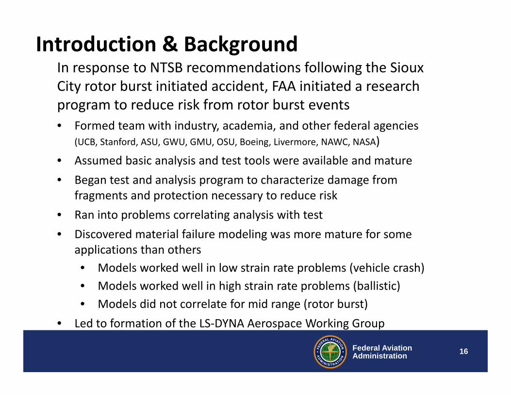
Introduction & BackgroundIn response to NTSB recommendations following the Sioux City rotor burst initiated accident, FAA initiated a research program to reduce risk from rotor burst events• Formed team with industry, academia, and other federal agencies
(UCB, Stanford, ASU, GWU, GMU, OSU, Boeing, Livermore, NAWC, NASA)• Assumed basic analysis and test tools were available and mature• Began test and analysis program to characterize damage from
fragments and protection necessary to reduce risk• Ran into problems correlating analysis with test• Discovered material failure modeling was more mature for some
applications than others• Models worked well in low strain rate problems (vehicle crash)• Models worked well in high strain rate problems (ballistic)• Models did not correlate for mid range (rotor burst)
• Led to formation of the LS‐DYNA Aerospace Working Group

17Federal AviationAdministration
Introduction & Background
Different modes of material failure result when the orientation of a complex fragment is varied
18Federal AviationAdministration
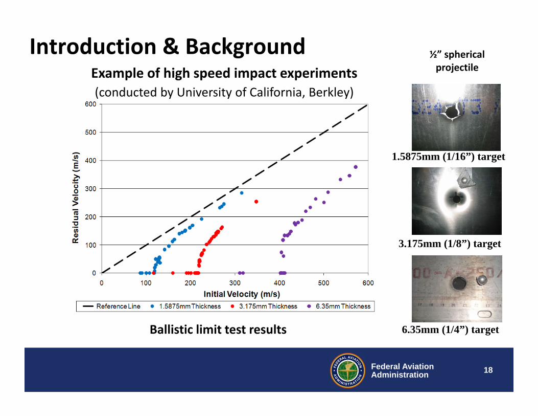
Ballistic limit test results
Introduction & BackgroundExample of high speed impact experiments(conducted by University of California, Berkley)
1.5875mm (1/16”) target
½” spherical projectile
3.175mm (1/8”) target
6.35mm (1/4”) target

19Federal AviationAdministration
Introduction & BackgroundTransition of the failure modes could not be predicted using one common Johnson‐Cook material model
1.5875mm 3.175mm 6.35mm315 m/s 348 m/s 571 m/s
Petaling Plugging1.
5875
mm
Petaling-Bending-Necking
3.17
5mm
Failure Mode Transition
6.35
mm
Plugging-Shearing

20Federal AviationAdministration
Develop a tabulated, thermo‐elastic/viscoplastic material model coupled with an accumulated regularized failure criterion that can incorporate high strain rate and temperature effects, and implement in LS‐DYNA MAT_224
• Develop a failure locus as a function of equivalent plastic strain at failure, stress triaxiality and Lode angle parameter.
• Develop a testing program to characterize strain‐rate and temperature dependent flow and failure surfaces.
• Implement the new material model into LS‐DYNA
• Validate the new material model against material specimen and impact tests
Material Model Research Objectives
21Federal AviationAdministration
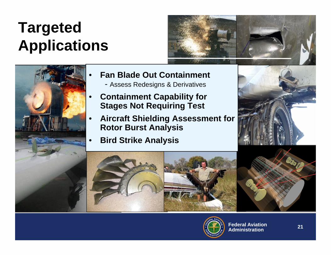
Targeted Applications
• Fan Blade Out Containment- Assess Redesigns & Derivatives
• Containment Capability for Stages Not Requiring Test
• Aircraft Shielding Assessment for Rotor Burst Analysis
• Bird Strike Analysis

22Federal AviationAdministration
Development of Material Failure Models for Aerospace Non-Linear Dynamics
• MAT 224 – (in LS-DYNA)Tabulated elastic/viscoplastic material model coupled with an accumulated regularized failure criterion that can incorporate high strain rate and temperature effects)
• MAT 224_GYS – (in LS-DYNA)Generalized isotropic yield surface model for pressure independent metal plasticity considering yield strength differential effect in tension, compression and shear stress states
– MAT 264 – (in LS-DYNA)Fully-tabulated 3D anisotropic plasticity model for transient dynamics of metals
23Federal AviationAdministration
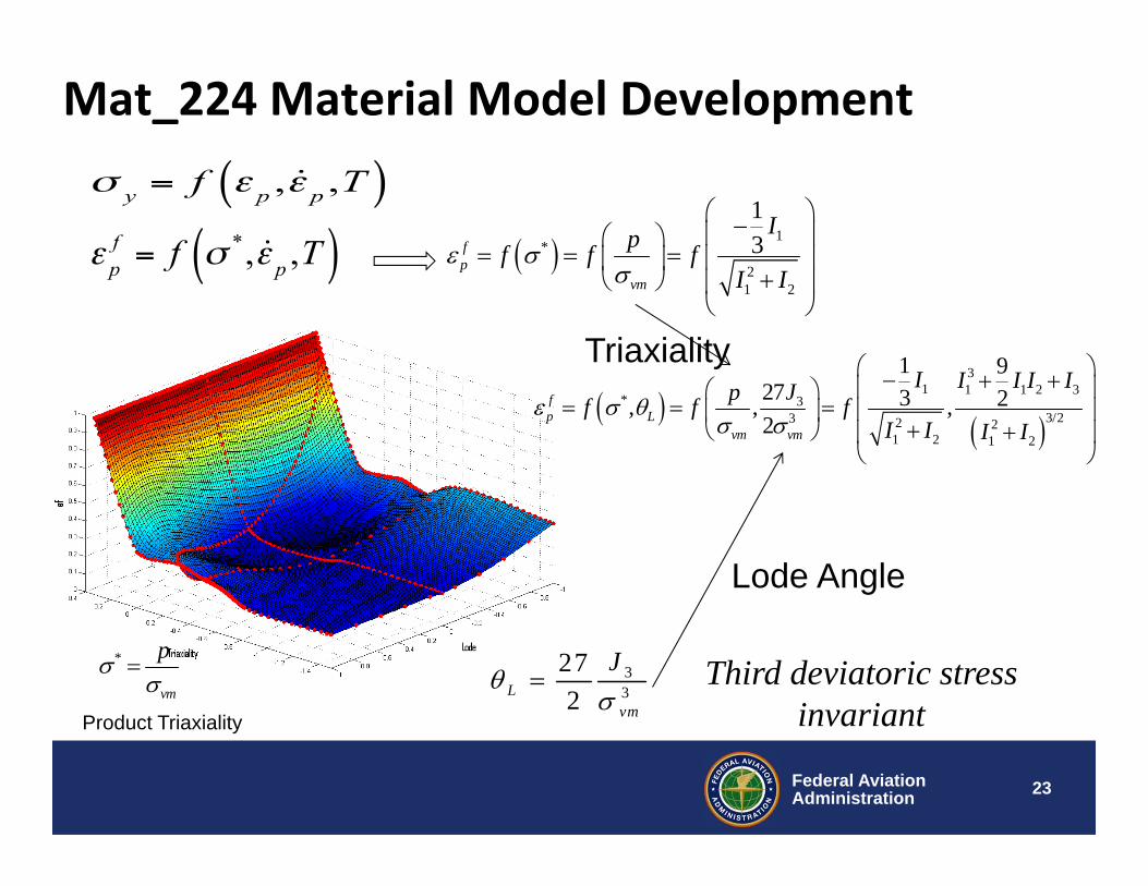
Mat_224 Material Model Development
1
*
21 2
13f
pvm
Ipf f fI I
33
272L
vm
J
31 1 1 2 3
* 33/23 2 2
1 2 1 2
1 927 3 2, , ,2
fp L
vm vm
I I I I IJpf f fI I I I
Third deviatoric stress invariant
*
vm
p
Triaxiality
Lode Angle
Product Triaxiality

24Federal AviationAdministration
Stress Triaxiality
Product Triaxiality
Lode Angle
Parameter
Illustration
Biaxial stress Tension 0 -1
Uni-axial StressTension, Confined Lateral
0 0
Uni-axial StressTension
0 1
Pure Shear0 0 0
Uni-axial StressCompression
0 -1
23
13
13
13
Range of Stress States Needed to Characterize Failure Surface
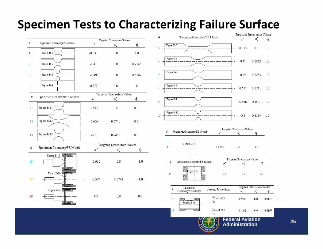
25Federal AviationAdministration
Specimen Tests to Characterizing Failure Surface

26Federal AviationAdministration
MAT_224 Material Model
Failure surface for Al2024‐T351
27Federal AviationAdministration
Generalized Isotropic Yield Model MAT_224_GYS• The MAT_224 yield function is not able to correctly
represent a material with a plastic strength differential (tension compression)
• MAT_224 is fully isotropic
• MAT_224_GYS introduces a Generalized Isotropic Yield Surface model for pressure independent metal plasticity
• Considers yield strength differential effects in tension, compression and shear stress states
• Tensile/compressive asymmetry is important for accurate modeling of HCP metals (e.g. Titanium)
28Federal AviationAdministration
Simulation of Experimental Data Using MAT224_GYS
• Differences in the Tension-Compression and Torsion for Aluminum (Al2024-T351) have been successfully simulated using MAT224_GYS.
• MAT224_GYS and MAT224 force-deflection output has been compared for uni-axial compression test
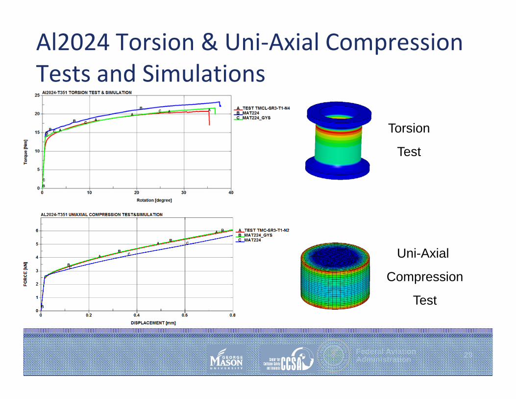
• GYS accurately predicts torque-rotation for the torsion test
• Tension-Compression asymmetry of Ti64 has been successfully simulated using MAT224_GYS.
• MAT224_GYS and MAT224 force-deflection output has been compared for uni-axial compression test
29Federal AviationAdministration
Al2024 Torsion & Uni‐Axial Compression Tests and Simulations
Torsion
Test
Uni-Axial
Compression
Test
30Federal AviationAdministration
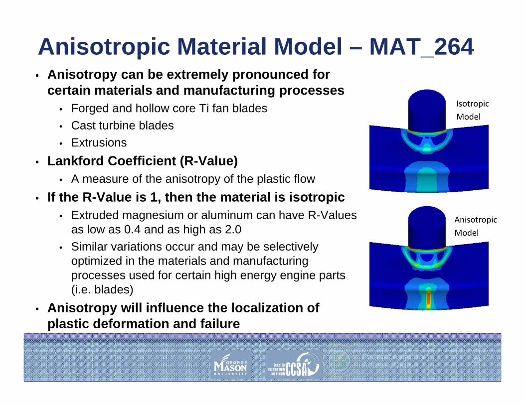
Anisotropic Material Model – MAT_264• Anisotropy can be extremely pronounced for
certain materials and manufacturing processes• Forged and hollow core Ti fan blades • Cast turbine blades• Extrusions
• Lankford Coefficient (R-Value)• A measure of the anisotropy of the plastic flow
• If the R-Value is 1, then the material is isotropic• Extruded magnesium or aluminum can have R-Values
as low as 0.4 and as high as 2.0• Similar variations occur and may be selectively
optimized in the materials and manufacturing processes used for certain high energy engine parts (i.e. blades)
• Anisotropy will influence the localization of plastic deformation and failure
IsotropicModel
AnisotropicModel
31Federal AviationAdministration
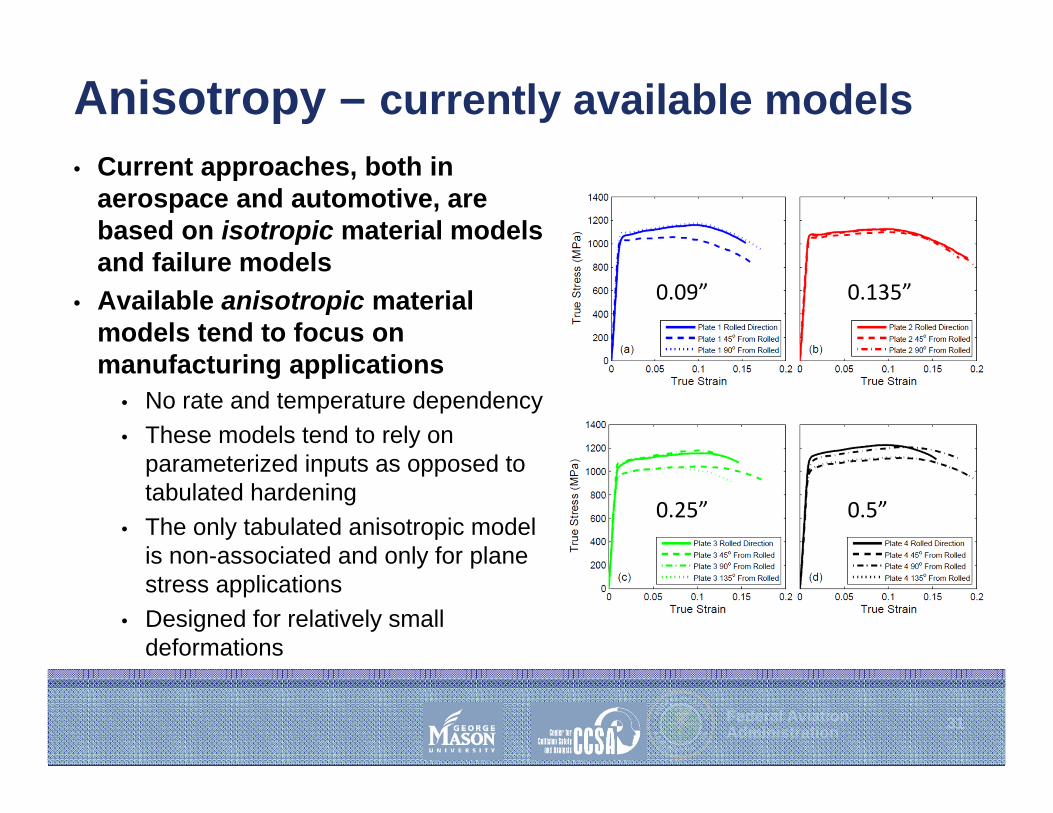
Anisotropy – currently available models• Current approaches, both in
aerospace and automotive, are based on isotropic material models and failure models
• Available anisotropic material models tend to focus on manufacturing applications
• No rate and temperature dependency• These models tend to rely on
parameterized inputs as opposed to tabulated hardening
• The only tabulated anisotropic model is non-associated and only for plane stress applications
• Designed for relatively small deformations
0.5”0.25”
0.135”0.09”

32Federal AviationAdministration
Approach – MAT264• Model simulates anisotropic plastic deformation
• Tabulated hardening curves allow simulation of test data (in all directions) for large deformations beyond necking
• Simulates asymmetric tensile/compressive response (typical for HCP metals) will be included
• Includes rate and temperature dependencies
• Model produces identical results to MAT_224 when implemented with isotropic/symmetric material properties, and produces identical results to MAT_224_GYS when implemented with isotropic/asymmetric material properties

33Federal AviationAdministration
Benefit of Anisotropic Material Model MAT_264

34Federal AviationAdministration
Future Material Model Development
1. Complete validation for MAT_264 (2016 – 2017)2. Develop failure surfaces/models for anisotropic
materials (2017 – 2018)3. Develop composite material models
(2015 - 2019)

35Federal AviationAdministration
Future Work – Apply to Fragment Impact Studies
Typical Small FragmentsThe HP turbine blade root mass, size, and tangential velocity make it a very significant fragment.
Generic Rectangular Projectile model used to assess impact obliquity
sensitivity
Secondary Benefit: develop statistical penetration risk model supporting UEDDAM
i axis
i axis i axis
36Federal AviationAdministration
Application examples– UEDDAM fragment barrier modeling – FBO blade containment modeling study– Open Rotor program test and analysis

37Federal AviationAdministration
UEDDAM – Uncontained Debris Damage Assessment Model• R&D task initiated under ARAC
PPIHWG to include analysis of multiple fragments impacting multiple locations
– Directive resulting from Sioux City
• UEDDAM is leveraged from existing DoD vulnerability assessment tools
– Joint work with NAWC, China Lake
• UEDDAM provides statistical assessment of debris pattern and uses statistical models to assess probability of damage
• Barrier shielding analysis will be performed with LS-DYNA
– Results used to create statistical models of barrier capability for UEDDAM
Sioux City Empennage DamageNTSB Rec’s
A90-170 AC20-128
A90-172 Debris Model

38Federal AviationAdministration
Rotor-burst Research with UEDDAM
• Once specific vulnerability is established, mitigation studies include:– System separation and
redundancy– Move critical components to shield
with aircraft structure – Develop additional protective
barrier – LS-DYNA used for detailed design
and analysis of impact events

39Federal AviationAdministration
Barrier Design example• Fabric Shielding
– SRI international initiated work– SRI Teamed with UC Berkeley and Boeing for aircraft shielding– LS-DYNA used for detailed design and analysis of impact
events

40Federal AviationAdministration
Application examples– UEDDAM fragment barrier modeling – FBO blade containment modeling study– Open Rotor program test and analysis

41Federal AviationAdministration
Fan Blade Out Rig Model• Develop a small diameter fan rig model that:
– Has fan dynamic characteristics of modern wide chord high bypass turbofan engine
• 40” dia fan, 20 blades, integrally bladed disk, solid wall containment
– Is capable of simulating the initial containment event• Blade release, impact with trail blade, containment, fragmentation
• Model will be used for:– Material model development studies– Containment method studies– Fan/case interaction studies– Initial event dynamics studies

42Federal AviationAdministration
Fan Rig Model
Fan Blade Out Rig Model• Simulates a development test rig,
not a full engine• Fan rigs are used by Engine OEM’s
to develop and validate containment systems
43Federal AviationAdministration
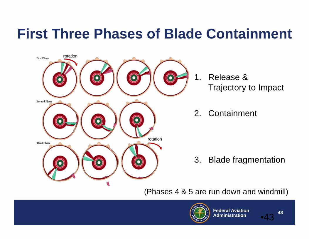
First Three Phases of Blade Containment
•43
1. Release & Trajectory to Impact
2. Containment
3. Blade fragmentation
rotation
rotation
(Phases 4 & 5 are run down and windmill)

44Federal AviationAdministration
Damage to the Containment Case at the Footprint of Root Impact
•44
Accurate replication of the blade out event is critical for accurately predicting case containment capability
45Federal AviationAdministration
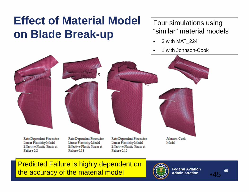
Effect of Material Model on Blade Break-up
•45
Four simulations using “similar” material models• 3 with MAT_224
• 1 with Johnson-Cook
Predicted Failure is highly dependent on the accuracy of the material model

46Federal AviationAdministration
FBO Containment ModelingStatus Today• Many OEM’s have developed a level of modeling
that allows them to address certain problems that have arisen in FBO testing
• To date, no OEM has developed a sufficiently predictive capability to use analysis in place of test for containment certification
• Analysis is used for derivative certification where containment has been demonstrated in the baseline model test and changes to containment via rig test – Analysis addresses: safe shut down, will not catch fire, and
mount integrity
47Federal AviationAdministration
Application examples– UEDDAM fragment barrier modeling – FBO blade containment modeling study– Open Rotor program test and analysis
48Federal AviationAdministration
Collaborative Program with:• NASA Glenn Research Center, Cleveland, Ohio• FAA William J. Hughes Technical Center, Atlantic City, NJ• Naval Air Warfare Center, Weapons Division, China Lake, CA
Analysis and Testing of a Composite Fuselage Shield for Open Rotor Engine Blade‐Out Protection
49Federal AviationAdministration
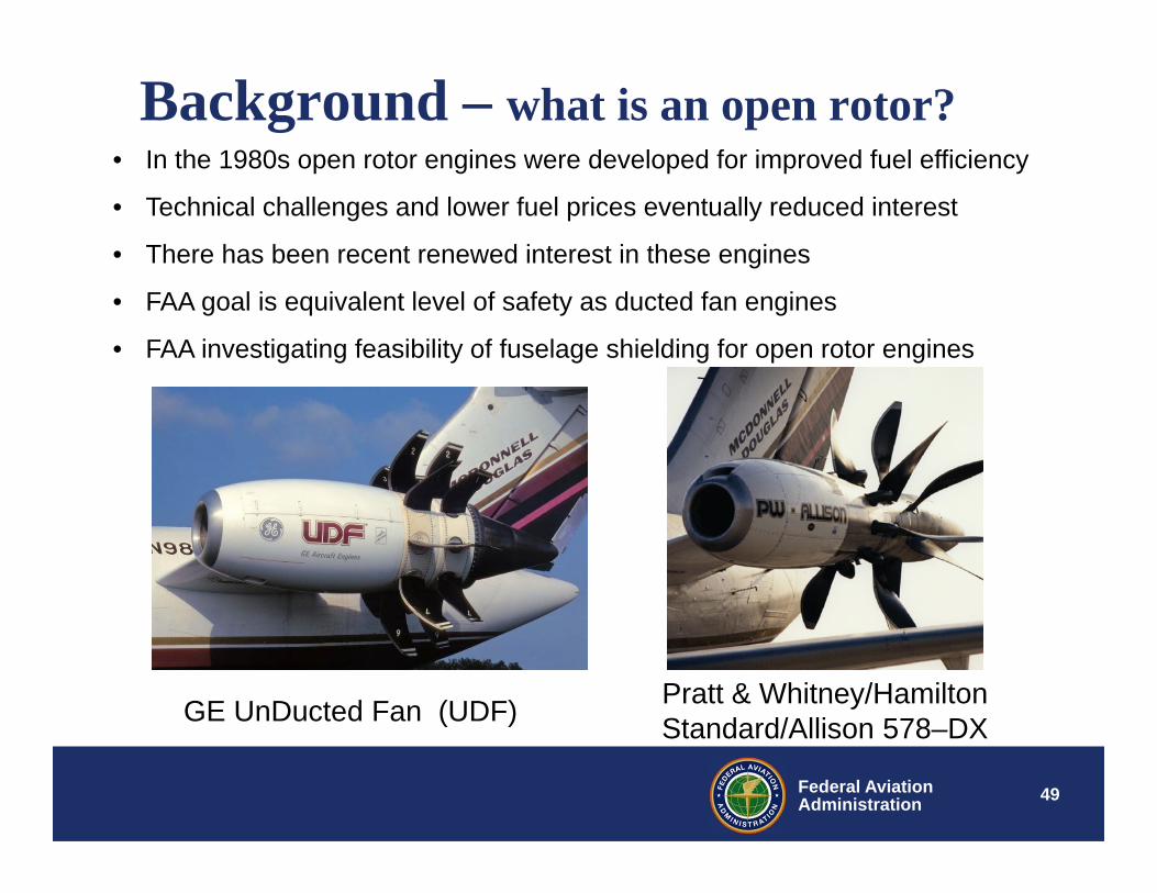
Background – what is an open rotor?
Pratt & Whitney/Hamilton Standard/Allison 578–DXGE UnDucted Fan (UDF)
• In the 1980s open rotor engines were developed for improved fuel efficiency
• Technical challenges and lower fuel prices eventually reduced interest
• There has been recent renewed interest in these engines
• FAA goal is equivalent level of safety as ducted fan engines
• FAA investigating feasibility of fuselage shielding for open rotor engines

50Federal AviationAdministration
FAA Open Rotor Shielding Feasibility Study• FAA selected a medium range aircraft configuration with a
high wing and wing mounted open rotor engines
• Trajectory analyses conducted at NASA/GRC to predict the blade release angles for the worst case impact scenario
• Computational analyses conducted at NASA/GRC to predict minimum composite shield thickness to prevent penetration
• LS-DYNA predictions based on model correlation with small scale ballistics testing• Test configuration design – worst case scenario• Full scale subcomponent test conducted at China Lake Naval Air Warfare Center
51Federal AviationAdministration
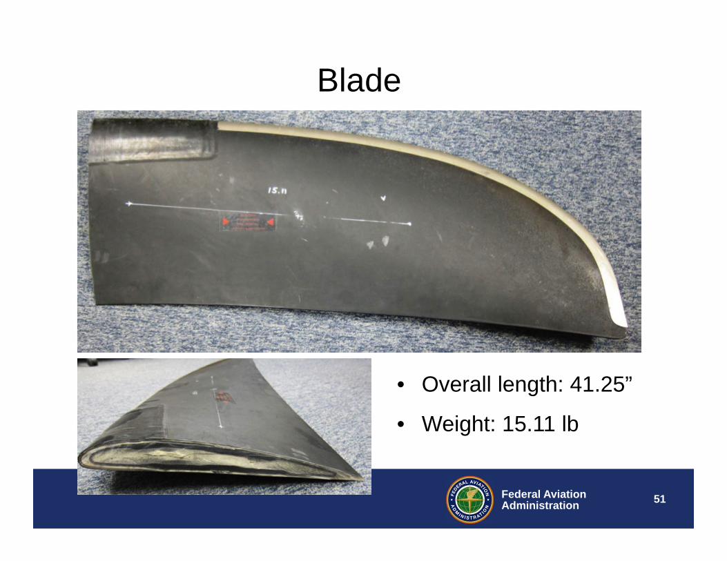
Blade
• Overall length: 41.25”
• Weight: 15.11 lb
52Federal AviationAdministration
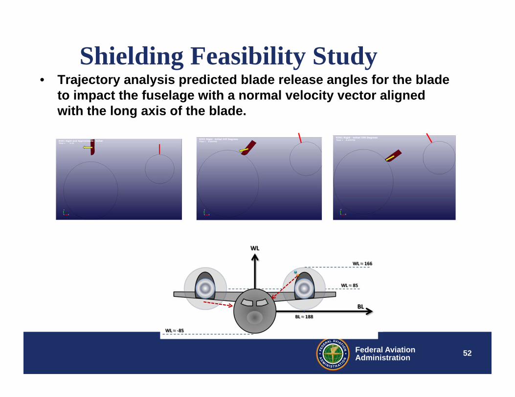
Shielding Feasibility Study• Trajectory analysis predicted blade release angles for the blade
to impact the fuselage with a normal velocity vector aligned with the long axis of the blade.

53Federal AviationAdministration
FAA Feasibility Study• Test Configuration Design

54Federal AviationAdministration
Pre-test Predictions• Pre-test simulations predicted that a 20 ply composite panel
would allow the blade to penetrate and a 24 ply panel would prevent penetration

55Federal AviationAdministration
Dynamic Open Rotor Composite Shield Test
•5
56Federal AviationAdministration
Test Observations
• Blade separation occurred at desired clock position• Blades separated cleanly from root section• Blades traveled to target panels impacting end on
(~90 degree impact)• Both blades impacted the target panels• Impact
– 24 ply panel - Deflected blade with no through crack– 20 ply panel – Blade penetrated panel
57Federal AviationAdministration
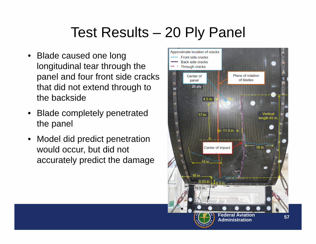
Test Results – 20 Ply Panel• Blade caused one long
longitudinal tear through the panel and four front side cracks that did not extend through to the backside
• Blade completely penetrated the panel
• Model did predict penetration would occur, but did not accurately predict the damage

58Federal AviationAdministration
Test Results – 24 Ply Panel
58
To help protect your privacy, PowerPoint has blocked automatic download of this picture.
59Federal AviationAdministration
Open Rotor Shielding Test Findings• Good global correlation with pretest predictions
• 24 Ply panel deflected the blade and did not have a thru failure– Localized, non-penetrating damage occurred
• 20 Ply panel was cracked completely through– Blade completely penetrated panel
– Model did predict penetration would occur, but did not accurately predict the degree of damage
• Crack was longer than pretest prediction.

60Federal AviationAdministration
Open Rotor Shielding Program Conclusions
• Composite shielding may be a feasible solution to fuselage shielding for open rotor engines
• For counter-rotating blades (2 rotors) shielding weight added estimated to be less than 250 lb.
• Advances in composite impact models needed to predict accurate failure modes and to be predictive rather than correlative
61Federal AviationAdministration
Closing Comments• Use of Analysis is becoming more prevalent• To substitute analysis for test requires
significant effort by the applicant:– Demonstration of modeling expertise
• Includes prior test/analysis demonstrations on which modeling experience & capability have been correlated
– Validation of model predictive capability• Recognize that validation is different from correlation
– Ability to close loop between predictions and expectations from predictions
• i.e. use of other tests to validate key components
– The model and modeling process must be auditable
62Federal AviationAdministration
FAA Resources For Non-Linear Analysis
• FAA 33.94 Fan Blade Out Rule Owner Engine & Propeller Directorate (ANE)– Jay Turnburg (781) 238-7116
• FAA Containment and Impact R&DW.J. Hughes Technical Center– Bill Emmerling (609) 485-4009– Dan Cordasco (609) 485-4970
• FAA Chief Scientist for Engine Dynamics– Chip Queitzsch (703) 915-5351
63Federal AviationAdministration
Organizations Participating in the FAA Non-Linear Analysis R&D Program• Government Agencies
– NASA Glenn Research Center– Naval Air Warfare Center, China Lake– Lawrence Livermore Laboratory
• Universities– George Mason University– Ohio State University– Arizona State University– George Washington University– University of California, Berkeley– Stanford
• Industry– Boeing– Honeywell– Pratt & Whitney– Stanford Research Institute

64Federal AviationAdministration
Questions?