non-destructive testing of materials used for protective ... · 1 non-destructive testing of...
TRANSCRIPT
1
Non-destructive Testing of Materials Used for Protective Structures Built from High Performance Fibre Reinforced
Concrete after the Contact Explosion Loading
Eva ZEZULOVA 1, Jiří ŠTOLLER 2
1 University of Defence, Department of Engineer Technology; Brno, Czech Republic.
Phone: +420 973 443 250; e-mail: [email protected] 2 University of Defence, Department of Engineer Technology; Brno, Czech Republic.
Phone: +420 973 443 282; e-mail: [email protected] Abstract The article deals with the use of the passage ultrasonic method for diagnosis of discontinuities, which result from the loading of the protective structure elements made from High Performance Fibre Reinforced Concrete (HPFRC) by PlNp 10 explosion. Within the research on new materials and structures suitable for temporary protective structures, the HPFRC material was tested. This material was chosen for testing due to its great mechanical and physical properties such as compressive strength, tensile strength and resistance to dynamic loads. The article compares material characteristics of the unreinforced concrete, steel fibre concrete (fibre reinforced concrete) and HPFRC on the basis of materials tested by using the passage ultrasonic method after the explosion. This method is one of the possible methods used for the non-destructive evaluation of experiments on protective structures. The requirements for a suitable method are low demands on instrumentation and operator´s experience. Contrary to these requirements, the searching method should provide reliable data about the testing of the protective structures. Keywords: materials characterization, Ultrasonic Testing (UT), NDT-wide, Protective structures, HPFRC, Explosion PlNp 10 1. Introduction The Army of the Czech Republic has been sending its personnel into peacekeeping operations since 1990. Until now, it has been approximately forty operations [1]. The protection of its own forces in these operations is a hot issue. It is ensured by protective structures placed not only in the base perimeter, but also inside the base. The key elements of the forces protection, which may not be missing at any base, are emergency shelters. The emergency shelter provides protection to the staff in the event of a missile attack on the base or, if necessary it offers circular defence of the base. These days the development of a new material is being worked on. Our Department of Engineer Technology is cooperating with the Czech Technical University in Prague and the Military Research Institute in Brno. The aim of the cooperation is to develop a new material that could withstand the load of the blast effect, impact and penetration much better. Nowadays, the materials used for ballistic protection are mostly materials on the metallic base, various non-cementitious composite materials and different kinds of concrete. Concrete is used for building temporary protective structures, mainly because of its ability to absorb a significant portion of the energy of the pressure wave. Concrete, the construction material widely used in civil engineering, shows two substantial disadvantages. It has a low tensile strength and fragile modus of disintegration. The ordinary structures contain reinforcement like steel beams, nets or spot-welded screens to eliminate those disadvantages. This reinforcement is capable of reducing disadvantages and when suitably placed, it can dissipate tensile stress and avert a fragile disintegration of the individual structure elements. The emplacement of the steel beam reinforcement can change the structure behaviour but the concrete features remain unchanged. The augmentation of the tensile strength and the change of fragile disintegration can be achieved by direct reinforcement of its structure. This augmentation is achievable by incorporation of support elements on the condition that their size corresponds to the size of the concrete structure components. The reinforcement of the
11th European Conference on Non-Destructive Testing (ECNDT 2014), October 6-10, 2014, Prague, Czech RepublicM
ore
Info
at O
pen
Acc
ess
Dat
abas
e w
ww
.ndt
.net
/?id
=16
660

2
structure is to be considered only as the strengthening of the structure of the cement composite by the dispersed reinforcement. This desired support element is a short wire. The significant feature of concrete is the facilitation of the wire reinforcement for all concrete production technologies. The wires affect not only features of the solid FRC, but also features of the FRC in the status of setting as well as in the pulpous status. A more suitable option might be another material called HPFRC (high performance fibre reinforced cementitious composite). The main advantage of the HPFRC is its high strength that permits reducing cross sections and thus decreases the mass of respective structures including its durability. It is estimated that the ballistic resistance of the HPFRC will significantly increase by adding the steel wires into concrete composition. After the completion of the material development, the further research will be focused on the development of protective structures components made of this material. Part of this research is the development of methods for the detection of discontinuities before and after the loading of protective structures by explosion, impact and penetration. The ultrasonic pulse velocity method is one of the possible ways to diagnose these protective structures. 2. Field tests of the slabs made from HPFRC (High Performance Fibres Reinforced Concrete) Concrete composites are materials with a promising future. The potential of the material has not fully been described and the characteristics of SFRC have not effectively been utilised. Many scientific institutions all over the world are doing research into cementitious composites to reveal new possibilities in mixing procedures and an optimal relationship of the constituents used, technology and resulting properties. 2.1 2. Test slabs The test samples (slabs 1000x1000x150 mm) for testing the resistance against shock wave were made from the high strength concrete reinforced with steel fibres (High Performance Fibres Reinforced Concrete - HPFRC), which is the material characterized by increased mechanical properties. The most important characteristic is the compressive strength, which must be greater than 60 MPa according to the regulations of the RILEM association. Another important parameter is the water tightness, which is caused by the special mixture of aggregate, sand and fine gravel. According to DIN EN 12390-8, leakage of pressure water reaches about 20 mm. Other important features include resistance to cyclic freezing and thawing – the material is resistant up to 150 to 200 cycles tested according to DIN EN 12390-9. All the above-mentioned properties allow the use of the HPFRC for the structures exposed to adverse weather conditions. Even in difficult climatic conditions, the material keeps its properties without expensive maintenance. 10 pieces of 50 mm thick slabs and 10 pieces of 100 mm thick slabs were made from the HPFRC for the field tests. There were also tested sandwich panels composed of three layers. The first of them was a 50 mm thick slab made from the HPFRC. The second was a 50 mm thick layer of insulation STERED. The third was a 100 mm thick HPFRC slab.

3
Fig. 1: The test sample before loading by TNT explosion 2.2 Layout of the experiment field The samples tested had two different dimensions - 50x1000x1000 mm and 100x1000x1000 mm. The test samples were placed in racks made of thin-walled closed steel profiles. The racks were fixed against displacement with wooden stakes. The slabs were tested in groups of three or four samples (Fig. 2 and Fig. 3) in one workplace. Each test consisted of two separated departments, it means of two blasts ignited simultaneously. The charge was situated in the middle of the test samples (see Fig. 2). The charges were placed above the ground at the height of the 500 mm. The charge was composed of engineer TNT charges. The charges, setting up and ignition were provided by the 15th Engineer Brigade.
Fig. 2: The layout of testing slabs and high-speed cameras during resistance test against the pressure wave.
. 3. Ultrasonic slabs measurements before and after TNT explosion. 3.1 Ultrasonic Pulse Velocity Method. The Ultrasonic Pulse Velocity (UPV) testing method is based on the measuring of the velocity of ultrasound wave in material. The propagation of the ultrasound waves is a function of the properties of the tested material (air 330 m.s-1, water 1500 m.s-1, steel 5000–6000 m.s-1, concrete 3000–5000 m.s-1). The ultrasonic wave is a mechanical wave with frequencies higher than 20 kHz, the velocity of which passing through construction materials depends on the physical and mechanical properties of the material as well as on the presence of defects in the structures. The Ultrasonic Pulse Velocity belongs to the group of the non-destructive testing

4
methods. The biggest advantage of those methods is the simplicity of the test performance. The disadvantages include the difficulty in interpreting the results in more complex cases, and the sensitivity of the ultrasound method to the whole range of external factors. For the ultrasonic testing of building structures and materials, probes with the operating frequency in the range from 20 kHz to 150 kHz are commonly used. The utilization of other frequencies is not very frequent; however, it is possible. Generally accepted, the resolution and the accuracy of ultrasound measurements are increased with a higher frequency of the ultrasound wave resolution. Nevertheless, high frequencies ultrasonic waves while passing through the structures are much more strongly attenuated. The recommendations for the Ultrasound Pulse Method [4] of concrete testing with regard to the behaviour of the ultrasonic pulse described above, are based on the Czech technical standard ČSN 73 1371[3] . for a short measuring base (up to 50 mm), it is appropriate to use a probe with a high
frequency of60 to 200 kHz, for a long measuring base (from 1 meter to 15 meters), it is appropriate to use a probe with a low operating frequency of 10 to 40 kHz, for most of the cases it is appropriate to use a probe with an operating frequency of 40 to 60 kHz.
It is necessary to draw attention to the fact that the applicability of a certain frequency probe for a specific case of measurement is given not only by the length of the measuring base, but also by other factors, such as the size of the defect or inhomogeneity, the type of material, the device power, etc. Basically, there are two main ways to test the properties of the structures or materials by ultrasound. The first of them is to measure the velocity of ultrasound wave in the tested material. This test detects the physical and mechanical characteristics of the tested material and its potential defects. The second way is the Ultrasonic Pulse Echo Method. This method captures reflections of the ultrasonic signal from inhomogeneity, defect or a foreign body in the structure [4]. For the testing of protective structures the Ultrasonic Pulse Velocity Method was chosen. This method is suitable for assessing the quality of the material and for recognising the changes that occur after the loading of slabs by TNT explosion. To determine the velocity of ultrasound, the passing time through a testing material of the ultrasonic pulses between the exciter and the sensor is measured (see Figure 3). The temperature of the sample in the range of +5 to +30 ° C does not influence the measurement results; thus, the measurement results do not require any correction.

5
Fig. 3: Measurement of the ultrasonic pulse velocity
During the measurement, the probe is in contact with the surface of the structure and a small air gap is formed. In this double border environment (metal probe – air, air – test sample) there is a significant reflection of ultrasonic waves. A passage of pulses is very low and in most cases, the sensitivity of the device is not sufficient to detect the incoming pulses. Therefore, it is necessary to use an acoustic coupling agent – a thin layer of air space between the probe and the sample is filled with a thin layer of a modelling clay, grease or ultrasound gel. It reduces the unwanted reflection of the waves and greatly enhances a passage of the waves through different environment. It is necessary to keep the probe clean because dirty gel can invalidate the measurement results. 3.2 Preparation of slabs, before their testing and loading by TNT explosion. Before testing, the slabs were provided with a square grid on both sides (reverse and facing) of each slab. On each side of the sample tested 49 points were drawn. Marginal points were placed 50 mm from the edge of the slab. The distance between the inner square grid points was 150 mm (see Fig. 4). Each point has been attributed by coordinates.
Fig. 4: Square grid on the both sides of each slab
The square grid has to be drawn by a water resistant paint that is applicable in the humid weather. In addition, the grid must be drawn thoroughly so that the points on the facing and reverse sides lie exactly opposite each other.

6
3.3 Measurement and evaluation of the velocity of ultrasound propagation. For measurements, the ultrasound device manufactured by UNIPAN was used. The distance L between the probes is measured by the conventional distance measurement methods with the accuracy of ± 0.5 %. The measured values were written into the tables and subsequently the velocity of the ultrasound propagation was calculated at every square grid point of the testing slabs. To illustrate the propagation of the ultrasound velocity in the individual points of the testing slabs, the program for the creation of izovels named 3D Field Pro 64 bit was used [5]. Primarily, this program has been designed for cartographers to create contour lines. The authors of this paper utilized this program for the graphical representation of the propagation of the ultrasonic waves velocity. The coordinates of each point are the same as the geographic coordinates of any point in 2D. The only change is in the heights value of the point as the velocity is inserted into the program instead of height. The procedure of entering the values of individual points in the programming environment is as follows: Data points uploading (Fig. 5)
Fig. 5: Data uploading of the individual points of the network.
In the windows “Add Point", the values of coordinates x and y of the point displayed on the desktop can be entered. The propagation of the ultrasound velocity is inserted into the program instead of the heights values. Another choice in the "Data points" is the "Add from file". This enables to import the data from the files, which is easier than typing the data points by hand (Figure 6).
Fig. 6: The list of the individual points in the table and their redrawing to the image area.
The values between the points can be interpolated, set, and edited. The visible area can be set and its colour band specified (Fig. 7). Then the programme draws the contours (izovels) according to the user requirements.

7
Obr. 7: Setting of the colour spectrum of your choice according to the velocity of ultrasonic waves.
If required, it is possible to add particular descriptions to the graphic field. The slab loaded by a 5 kg TNT explosion at a distance of 3,000 mm. The layout of the HPFRC testing slabs no. high-speed cameras and explosives, see Fig.8.
Fig. 8 The layout of the HPFRC testing slabs no.2 and high-speed cameras during loading by a 5 kg TNT.
Izovels distributions in the HPFRC slab no.2 before and after the loading by a 5 kg TNT explosion at a distance of 3,000 mm (see Figure 9).
8
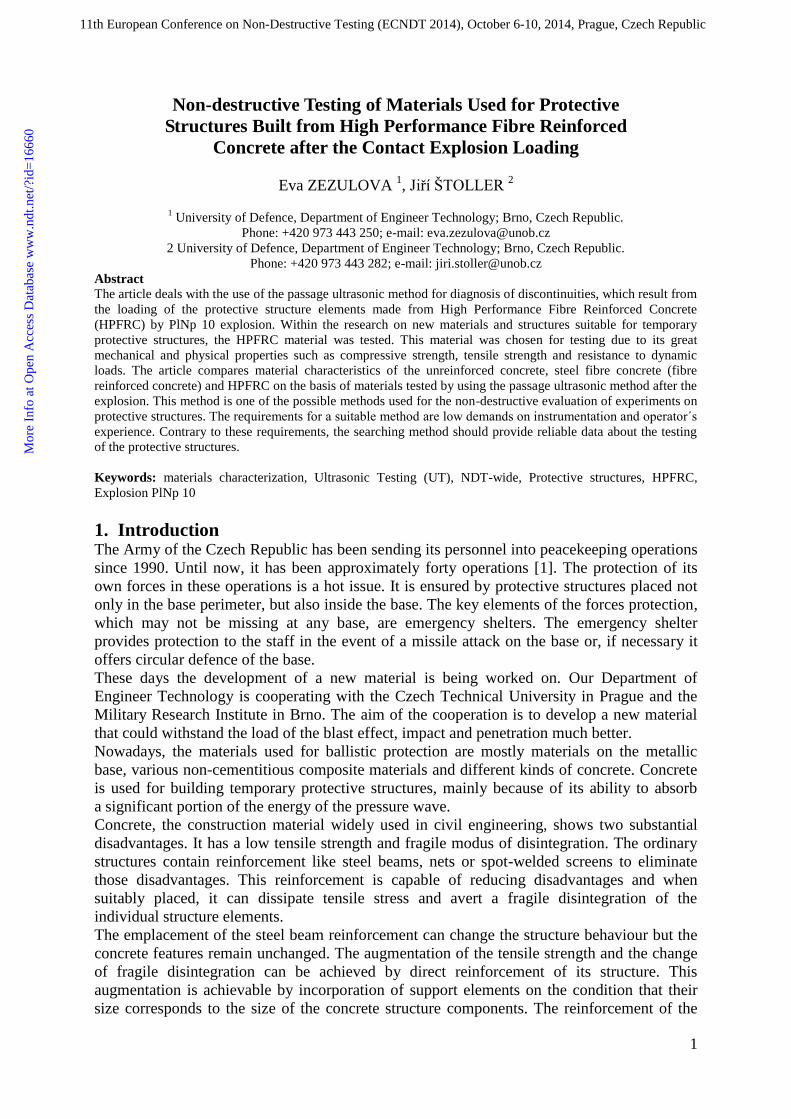
Fig. 9 Izovels distribution in the HPFRC slab no.2
before the explosion Fig. 10: Izovels distribution in the HPFRC slab no.2
after explosion
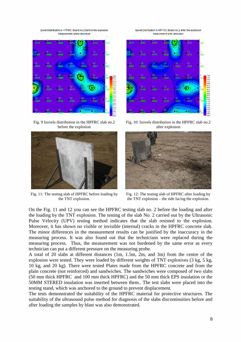
Fig. 11: The testing slab of HPFRC before loading by
the TNT explosion. Fig. 12: The testing slab of HPFRC after loading by the TNT explosion – the side facing the explosion.
On the Fig. 11 and 12 you can see the HPFRC testing slab no. 2 before the loading and after the loading by the TNT explosion. The testing of the slab No. 2 carried out by the Ultrasonic Pulse Velocity (UPV) testing method indicates that the slab resisted to the explosion. Moreover, it has shown no visible or invisible (internal) cracks in the HPFRC concrete slab. The minor differences in the measurement results can be justified by the inaccuracy in the measuring process. It was also found out that the technicians were replaced during the measuring process. Thus, the measurement was not burdened by the same error as every technician can put a different pressure on the measuring probe. A total of 20 slabs at different distances (1m, 1.5m, 2m, and 3m) from the centre of the explosion were tested. They were loaded by different weights of TNT explosives (3 kg, 5 kg, 10 kg, and 20 kg). There were tested Plates made from the HPFRC concrete and from the plain concrete (not reinforced) and sandwiches. The sandwiches were composed of two slabs (50 mm thick HPFRC and 100 mm thick HPFRC) and the 50 mm thick EPS insulation or the 50MM STERED insulation was inserted between them.. The test slabs were placed into the testing stand, which was anchored to the ground to prevent displacement. The tests demonstrated the suitability of the HPFRC material for protective structures. The suitability of the ultrasound pulse method for diagnosis of the slabs discontinuities before and after loading the samples by blast was also demonstrated.
9
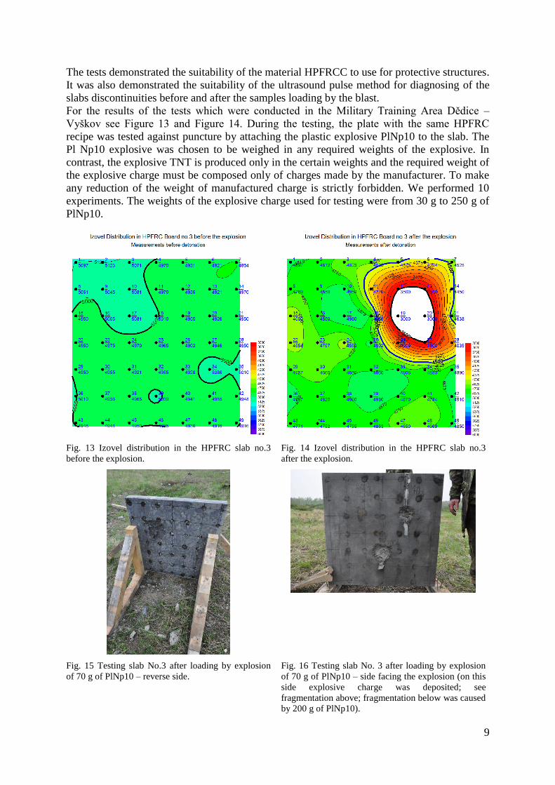
The tests demonstrated the suitability of the material HPFRCC to use for protective structures. It was also demonstrated the suitability of the ultrasound pulse method for diagnosing of the slabs discontinuities before and after the samples loading by the blast. For the results of the tests which were conducted in the Military Training Area Dědice – Vyškov see Figure 13 and Figure 14. During the testing, the plate with the same HPFRC recipe was tested against puncture by attaching the plastic explosive PlNp10 to the slab. The Pl Np10 explosive was chosen to be weighed in any required weights of the explosive. In contrast, the explosive TNT is produced only in the certain weights and the required weight of the explosive charge must be composed only of charges made by the manufacturer. To make any reduction of the weight of manufactured charge is strictly forbidden. We performed 10 experiments. The weights of the explosive charge used for testing were from 30 g to 250 g of PlNp10.
Fig. 13 Izovel distribution in the HPFRC slab no.3 before the explosion.
Fig. 14 Izovel distribution in the HPFRC slab no.3 after the explosion.
Fig. 15 Testing slab No.3 after loading by explosion of 70 g of PlNp10 – reverse side.
Fig. 16 Testing slab No. 3 after loading by explosion of 70 g of PlNp10 – side facing the explosion (on this side explosive charge was deposited; see fragmentation above; fragmentation below was caused by 200 g of PlNp10).
10
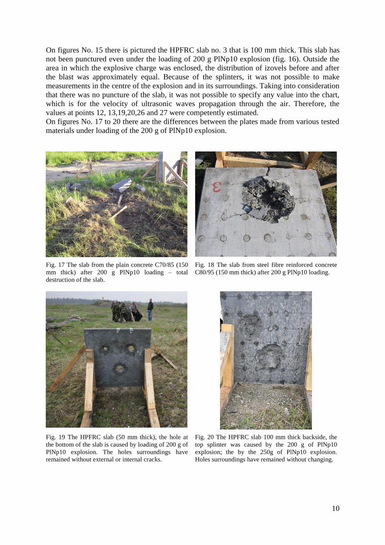
On figures No. 15 there is pictured the HPFRC slab no. 3 that is 100 mm thick. This slab has not been punctured even under the loading of 200 g PlNp10 explosion (fig. 16). Outside the area in which the explosive charge was enclosed, the distribution of izovels before and after the blast was approximately equal. Because of the splinters, it was not possible to make measurements in the centre of the explosion and in its surroundings. Taking into consideration that there was no puncture of the slab, it was not possible to specify any value into the chart, which is for the velocity of ultrasonic waves propagation through the air. Therefore, the values at points 12, 13,19,20,26 and 27 were competently estimated. On figures No. 17 to 20 there are the differences between the plates made from various tested materials under loading of the 200 g of PlNp10 explosion.
Fig. 17 The slab from the plain concrete C70/85 (150 mm thick) after 200 g PlNp10 loading – total destruction of the slab.
Fig. 18 The slab from steel fibre reinforced concrete C80/95 (150 mm thick) after 200 g PlNp10 loading.
Fig. 19 The HPFRC slab (50 mm thick), the hole at the bottom of the slab is caused by loading of 200 g of PlNp10 explosion. The holes surroundings have remained without external or internal cracks.
Fig. 20 The HPFRC slab 100 mm thick backside, the top splinter was caused by the 200 g of PlNp10 explosion; the by the 250g of PlNp10 explosion. Holes surroundings have remained without changing.
11
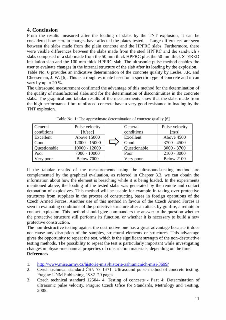
4. Conclusion From the results measured after the loading of slabs by the TNT explosion, it can be considered how certain charges have affected the plates tested. . Large differences are seen between the slabs made from the plain concrete and the HPFRC slabs. Furthermore, there were visible differences between the slabs made from the steel HPFRC and the sandwich´s slabs composed of a slab made from the 50 mm thick HPFRC plus the 50 mm thick STERED insulation slab and the 100 mm thick HPFRC slab. The ultrasonic pulse method enables the user to evaluate changes in the internal structure of the slab after its loading by the explosion. Table No. 6 provides an indicative determination of the concrete quality by Leslie, J.R. and Cheeseman, J. W. [6]. This is a rough estimate based on a specific type of concrete and it can vary by up to 20 %. The ultrasound measurement confirmed the advantage of this method for the determination of the quality of manufactured slabs and for the determination of discontinuities in the concrete slabs. The graphical and tabular results of the measurements show that the slabs made from the high performance fibre reinforced concrete have a very good resistance to loading by the TNT explosion.
Table No. 1: The approximate determination of concrete quality [6]
General conditions
Pulse velocity [ft/sec]
General conditions
Pulse velocity [m/s]
Excellent Above 15000 Excellent Above 4500 Good 12000 - 15000 Good 3700 - 4500 Questionable 10000 - 12000 Questionable 3000 - 3700 Poor 7000 - 10000 Poor 2100 - 3000 Very poor Below 7000 Very poor Below 2100
If the tabular results of the measurements using the ultrasound-testing method are complemented by the graphical evaluation, as referred in Chapter 3.3, we can obtain the information about how the element is breaching while it is being loaded. In the experiments mentioned above, the loading of the tested slabs was generated by the remote and contact detonation of explosives. This method will be usable for example in taking over protective structures from suppliers in the process of constructing bases in foreign operations of the Czech Armed Forces. Another use of this method in favour of the Czech Armed Forces is seen in evaluating conditions of the protective structure after an attack by gunfire, a remote or contact explosion. This method should give commanders the answer to the question whether the protective structure still performs its function, or whether it is necessary to build a new protective construction. The non-destructive testing against the destructive one has a great advantage because it does not cause any disruption of the samples, structural elements or structures. This advantage gives the opportunity to repeat the test, which is the significant strength of the non-destructive testing methods. The possibility to repeat the test is particularly important while investigating changes in physic-mechanical properties of construction materials, depending on the time. References 1. http://www.mise.army.cz/historie-misi/historie-zahranicnich-misi-3699/ 2. Czech technical standard ČSN 73 1371. Ultrasound pulse method of concrete testing.
Prague: ÚNM Publishing, 1982. 20 pages. 3. Czech technical standard 12504- 4. Testing of concrete - Part 4: Determination of
ultrasonic pulse velocity. Prague: Czech Ofice for Standards, Metrology and Testing, 2005.

12
4. Hobst, L.; Adámek, J.; Cikrle, P.; Schmid, P.; Diagnostics of constructions. Brno University of Technology, Brno, 2005.
5. http://3dfmaps.com/ 6. CIKRLE, P.; KOCÁB, D.; POSPÍCHAL, O. Possibilities of ultrasonic methods utilization
for determining of the compressive strength of concrete bridge. In Conference Testing and quality in construction. Proceedings reviewed contributions 2011. Brno: Brno University of Technology, 2011. page 53-60. ISBN: 978-80-214-4338- 9.