non-contact safety switches ces/cem - sensors incorporated
TRANSCRIPT

More than safety.
CES/CEMCES/CEMTransponderCoding
Non-ContactSafety Switches
2
Quality, reliability, precision
Quality, reliability and precision are thehallmarks of our corporate philosophy.They represent concepts and valuesto which we feel totally committed. At EUCHNER, quality means that allour employees take personal respon-sibility for the company as a wholeand, in particular, for their own field ofwork. This individual commitment toperfection results in products whichare ideally tailored to the customers’needs and the requirements of themarket. After all: our customers andtheir needs are the focus of all ourefforts. Through efficient and effectiveuse of resources, the promotion ofpersonal initiative and courage in find-ing unusual solutions to the benefit ofour customers, we ensure a high levelof customer satisfaction. We familiar-ize ourselves with their needs, require-ments and products and we learnfrom the experiences of our cus-tomers’ own customers.
EUCHNER – More than safety.
Quality – made by EUCHNER
More than safety.Around the world – the Swabianspecialists in motion sequencecontrol for mechanical and sys-tems engineering.
EUCHNER’s history began in 1940 withthe establishment of an engineeringoffice by Emil Euchner. Since thattime, EUCHNER has been involved inthe design and development of switch-gear for controlling a wide variety ofmotion sequences in mechanical andsystems engineering. In 1953, EmilEuchner founded EUCHNER + Co., amilestone in the company’s history. In1952, he developed the first multiplelimit switch – to this day a symbol ofthe enterprising spirit of this family-owned company.
Automation – Safety – ManMachine
Today, our products range fromelectromechanical and electroniccomponents to complex system solu-tions. With this wide range of productswe can provide the necessary tech-nologies to offer the right solution forspecial requirements – regardless ofwhether these relate to reliable andprecise positioning or to componentsand systems for safety engineering inthe automation sector.EUCHNER products are sold through aworld-wide sales network of compe-tent partners. With our closeness tothe customer and the guarantee ofreliable solutions throughout theglobe, we enjoy the confidence of cus-tomers all over the world.
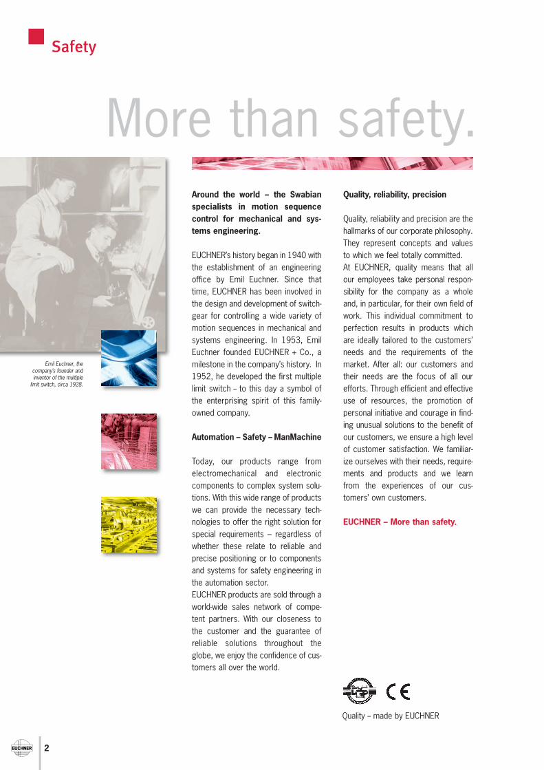
Emil Euchner, the company’s founder andinventor of the multiple
limit switch, circa 1928.
Safety

3
Contents
Connection cables 62Plug connector 66Safety screws 66Insertion tool for actuator CES-A-BMB 66
Accessories
General information 4
Selection table safety switches CES/CEM 6
Evaluation unit 8
Connection of 1 read head 8Connection of up to 2 or 4 read heads 14Evaluation unit in standard housing 24
Evaluation unit in standard housing with position sensor 30
Read heads/actuators CES 36CES series read heads 36CES series actuators 44
Read heads/actuators CEM 48Functional description 48CEM series read heads 50CEM series actuators 60
Non-Contact Safety Switches CES/CEM
Technical Status 06-03/06
Appendix
Definition of terms 67Index 68

4
Non-Contact Safety Switches CES/CEM
Subject to technical modifications; no responsibility is accepted for the accuracy of this information.
General information
According to EN 1088, interlocking devices are mechanical orelectrical devices which are designed to prevent the operation ofa machine element for as long as the movable safety guard is leftopen.
Non-contact safety switches are interlocking devices which aredesigned to protect people and machines.Compared with electromechanical safety switches, they are usedif:
Thanks to the highly integrated circuits contained in the actuatorand the read head, switches with transponder technology can beproduced in units of virtually any tiny design.EUCHNER also supplies read heads and actuators in rectangularand circular designs, with or without plug connectors.
The read head is fastened to the fixed part of the safety guardand is connected to the evaluation unit via a two-core screenedcable.The actuator fastened to the safety guard is moved towards theread head by closing the door. When the switch-on distance isreached, power is supplied to the actuator by the inductive readhead and data can be transferred.The bit pattern read is compared with the code saved in theevaluation unit; if the data matches, the safety outputs are enabledand the door monitoring output OUT (semiconductor output) isalso set HIGH.
Actuator and read head have a wide operating distance and abroad hysteresis. Misalignment of the doors will not result in thesystem switching off unintentionally. If, on the other hand, theactuator is positioned exactly at the limit of the switch-on distance,vibrations at the safety guard will not cause the machine to stopunintentionally.
Polling of the read head, "actuator present," is single-channel anddynamic. All potential faults (e.g. broken cable, short circuit, failureof the actuator) are reliably detected. Thanks to the redundant,diverse design of the evaluation unit in combination with two safetyoutputs, the evaluation unit enters the safe state with everydetectable fault.
a high level of protection against tampering must be achieved
extremely hygienic environmental conditions are required (e.g.in the food industry)
a precise door guide is not possible
machine doors are subjected to strong vibrations
a high safety category is determined in the risk analysis
Functional descriptionThe Coded Electronic Safety switch CES manufactured byEUCHNER comprises three components:
Coded actuator Read head Evaluation unit
The non-contact safety switches described here operate on thebasis of a uniquely electronically coded actuator (transponder).
The name transponder is a combination of the two termstransmitter and responder.The function of a transponder is easily explained: the transponder(actuator) receives and processes the electromagnetic field froma transceiver (read head), and the data signals are then sent backto the receiver (evaluation unit) as a response depending on thetransponder coding.
This transponder technology has been used successfully inelectronic immobilizers for many years by almost all automotivemanufacturers.Transponder technology is also used on the non-contact safetyswitches series CES from EUCHNER and is an advanced solutionfor a new safety concept.
Power is supplied and data transmitted to the coded actuatorusing a non-contact, inductive read head. The major advantage ofthe system is the battery-less actuator technology that will givethe user many years of service-free operation.
Every transponder is unique and absolutely secure against tampe-ring.The configuration of the system can be changed using a "teach-inoperation". In service new actuators can be taught very simply.Each delivered actuator possesses a unique electronic codingand so is a unique element in the system used. The code of theactuator cannot be reprogrammed.Signal transmission between the actuator and the read head isachieved via a homogeneous field. It is permissible to rotate theactuator within the operating distance of the read head.
5
Non-Contact Safety Switches CES/CEM
Subject to technical modifications; no responsibility is accepted for the accuracy of this information.
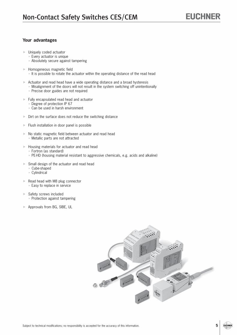
Your advantages
Uniquely coded actuator Every actuator is unique Absolutely secure against tampering
Homogeneous magnetic field It is possible to rotate the actuator within the operating distance of the read head
Actuator and read head have a wide operating distance and a broad hysteresis Misalignment of the doors will not result in the system switching off unintentionally Precise door guides are not required
Fully encapsulated read head and actuator Degree of protection IP 67 Can be used in harsh environment
Dirt on the surface does not reduce the switching distance
Flush installation in door panel is possible
No static magnetic field between actuator and read head Metallic parts are not attracted
Housing materials for actuator and read head Fortron (as standard) PE-HD (housing material resistant to aggressive chemicals, e.g. acids and alkaline)
Small design of the actuator and read head Cube-shaped Cylindrical
Read head with M8 plug connector Easy to replace in service
Safety screws included Protection against tampering
Approvals from BG, SIBE, UL

6
Non-Contact Safety Switches CES/CEM
Subject to technical modifications; no responsibility is accepted for the accuracy of this information.
Selection table safety switches CES with relay output
Evaluation units Read heads Actuators Connection cables
CES-A-ABA-01 Page 10- For 1 read head- Safety category 3- Switch-on distance 6 mm
CES-A-ABA-01B Page 10- For 1 read head- Safety category 3- Switch-on distance 15 mm
CES-A-AEA-02B Page 16- For 1 ... 2 read heads- Safety category 4- Switch-on distance 15 mm- Feedback loop/start button
CES-A-AEA-04B Page 18- For 1 ... 4 read heads- Safety category 4- Switch-on distance 15 mm- Feedback loop/start button
CES-A-LNA Page 36- Cube-shaped design- Fortron housing- PVC/PUR connection cable
CES-A-BBA Page 44- Cube-shaped design- Fortron housing
Eval
uatio
n un
its w
ith r
elay
out
put,
IP 2
0
CES-A-LCA Page 40- Cube-shaped design- PE-HD housing- PVC connection cable
CES-A-BCA Page 44- Cube-shaped design- PE-HD housing
CES-A-LNA Page 36- Cube-shaped design- Fortron housing- PVC/PUR connection cable
CES-A-BDA Page 46- Round design- ∅ 20 mm
M8 plug connectorConnection cablePUR/PVCsee page 64
CES-A-LNA-SC Page 38- Cube-shaped design- Fortron housing- M8 plug connector
CES-A-BBA Page 44- Cube-shaped design- Fortron housing
No additional connectioncable necessary
No additional connectioncable necessary
No additional connectioncable necessary
M8 plug connectorConnection cablePUR/PVCsee page 64
CES-A-LMN-SC Page 42- Cylindrical design M12- M8 plug connector
CES-A-BMB Page 47- Cylindrical design M12

7
Non-Contact Safety Switches CES/CEM
Subject to technical modifications; no responsibility is accepted for the accuracy of this information.
Evaluation unit with integrated read head Actuators Connection cables
CES-A-ABA-01B Page 10- For 1 read head- Safety category 3- Switch-on distance 2 mm
Eval
uatio
n un
its w
ith r
elay
out
put,
IP 2
0
M8 plug connector for so-lenoid operating voltagesee page 62
M8 plug connector forevaluation unitsee page 64
CEM-A-LE05K-S2 Page 50- Locking force 500 N
CEM-A-BE05 Page 60
M8 plug connector for so-lenoid operating voltagesee page 62
M8 plug connector forevaluation unitsee page 64
M8 plug connector forexternal LED indicatorsee page 63
CEM-A-LH10K-S3 Page 54- Locking force 1000 N
CEM-A-BH10 Page 61
Selection table safety switches CES with semiconductor output
Evaluation units Read heads Actuators Connection cables
Selection table safety switches CEM with solenoids
Eval
uatio
n un
its w
ith s
emic
ondu
ctor
out
put,
IP 6
7
CES-A-C5E-01 Page 26- Integrated read head- Safety category 3- Switch-on distance 20 mm
CES-A-C5H-01 Page 26- Integrated read head- Safety category 4- Switch-on distance 20 mm
Safety door actuatorCES-A-BBA Page 44- Fortron housing
Safety door actuatorCES-A-BCA Page 44- PE-HD housing
M12 plug connectorPVC connection cablesee page 65
M12 plug connectorPVC connection cablesee page 65
CES-A-AEA-02B Page 16- For 1 ... 2 read heads- Safety category 4- Switch-on distance 2 mm- Feedback loop/start button
CES-A-AEA-04B Page 18- For 1 ... 4 read heads- Safety category 4- Switch-on distance 2 mm- Feedback loop/start button
CES-A-S5H-01 Page 32- Position sensor- Integrated read head- Safety category 4- Switch-on distance 20 mm
Safety door actuatorCES-A-BBA Page 44- Fortron housing
Position actuatorCES-A-NBA Page 45- Fortron housing
M12 plug connectorPVC connection cablesee page 65
M12 plug connectorPVC connection cablesee page 65
CEM-A-LE05R-S2 Page 52- Without remanence
CEM-A-LH10R-S3 Page 56- Without remanence

8
Non-Contact Safety Switches CES/CEM
Subject to technical modifications; no responsibility is accepted for the accuracy of this information.
Evaluation unit CES-A-ABA...
Housing for DIN rail mounting, IP 20 Relay output 1 read head can be connected
Functional descriptionThe Coded Electronic Safety switch CES comprises threecomponents:
Coded actuator
Read head
Evaluation unit
The evaluation unit CES-A-ABA-01 is suitable for the directconnection of a read head, i.e. in each case, the code from onlyone actuator is read and processed.The teaching of other actuators can be initiated with a teach-inoperation. The teach-in operation can be performed up to 8 timeswith a new actuator; the actuator from the last teach-in is alwaysthe valid actuator. The evaluation unit in the DIN rail housing, degreeof protection IP 20, is suitable for installation in the control cabinet.
The two-core connection cable to the evaluation unit is hard-wiredto the read head or can be plugged in using a round M8 plugconnector. In this way, the wiring work is reduced to an absoluteminimum.
The read head is fastened to the fixed part of the safety guardand is connected to the evaluation unit via a two-core screenedcable.The actuator fastened to the movable part of the safety guard ismoved towards the read head by closing the door. When the switch-on distance is reached, power is supplied to the actuator by theinductive read head and data can be transferred.
The bit pattern read is compared with the code saved in theevaluation unit; if the data matches, the safety outputs (relay output)are enabled and the door monitoring output OUT (semiconductoroutput) is also set HIGH.Due to the combination of dynamic polling of the actuator and theredundant, diverse design of the safety electronics with the twosafety outputs, the evaluation unit will enter the safe state withevery detectable fault.When the safety guard is opened, the safety outputs switch offthe safety circuit and the door monitoring output (OUT) is switchedLOW. The state of the safety outputs is monitored internally bypositively driven NC contacts (relay output).If an internal fault occurs in the evaluation unit, the safety circuit isswitched off, the diagnostic output (ERROR) is set HIGH and theERROR LED illuminates red.
The safety contacts on the safety switch CES can switch currentsfrom 1 mA to 6 A. Since small currents can be switched, the userhas the option of connecting the safety switch CES directly to asafe control system.Safe control systems will become increasingly important astechnology progresses.
With a switching capacity of DC 24 V / 6 A, the evaluation unit canbe connected directly to the majority of power contactors, withoutfurther coupling modules.
9
Non-Contact Safety Switches CES/CEM
Subject to technical modifications; no responsibility is accepted for the accuracy of this information.
Your advantages
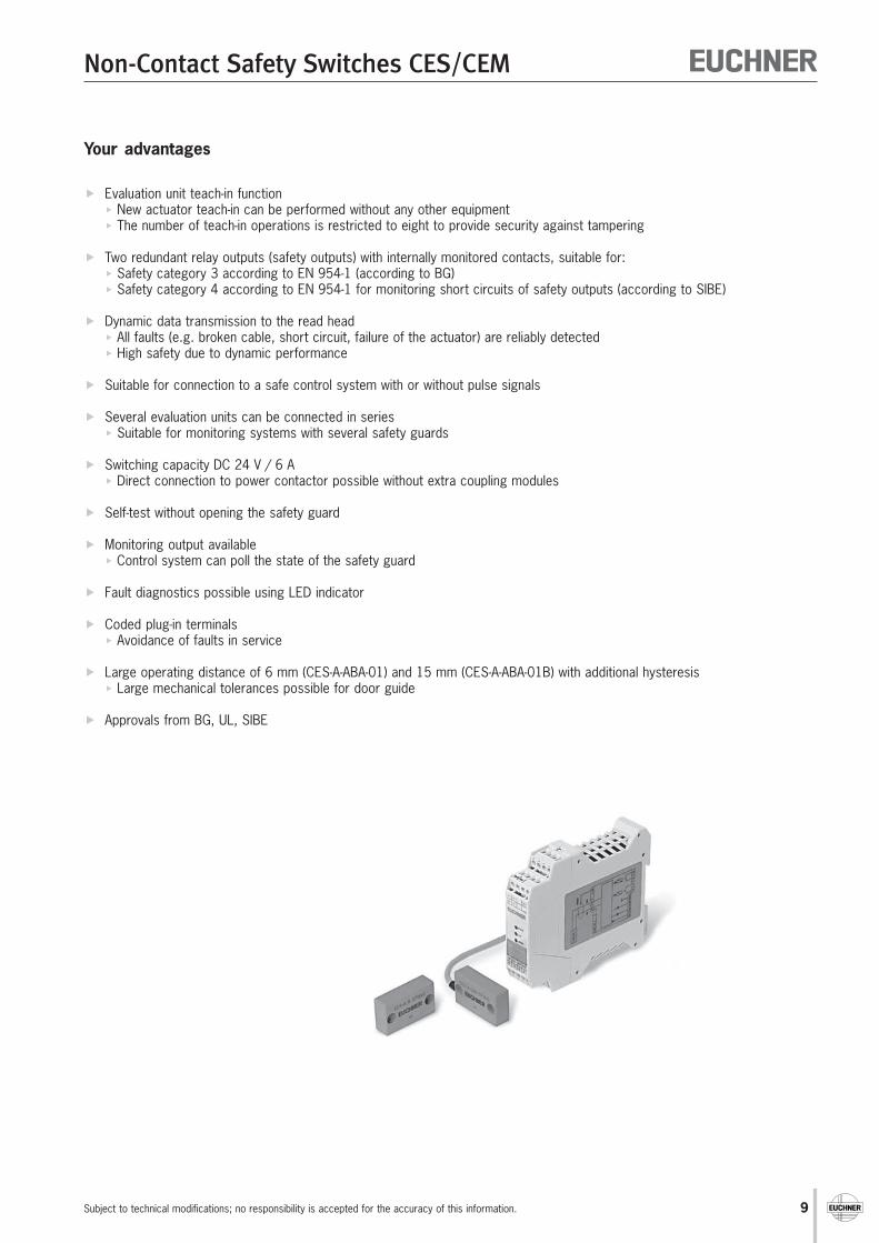
Evaluation unit teach-in function New actuator teach-in can be performed without any other equipment The number of teach-in operations is restricted to eight to provide security against tampering
Two redundant relay outputs (safety outputs) with internally monitored contacts, suitable for: Safety category 3 according to EN 954-1 (according to BG) Safety category 4 according to EN 954-1 for monitoring short circuits of safety outputs (according to SIBE)
Dynamic data transmission to the read head All faults (e.g. broken cable, short circuit, failure of the actuator) are reliably detected High safety due to dynamic performance
Suitable for connection to a safe control system with or without pulse signals
Several evaluation units can be connected in series Suitable for monitoring systems with several safety guards
Switching capacity DC 24 V / 6 A Direct connection to power contactor possible without extra coupling modules
Self-test without opening the safety guard
Monitoring output available Control system can poll the state of the safety guard
Fault diagnostics possible using LED indicator
Coded plug-in terminals Avoidance of faults in service
Large operating distance of 6 mm (CES-A-ABA-01) and 15 mm (CES-A-ABA-01B) with additional hysteresis Large mechanical tolerances possible for door guide
Approvals from BG, UL, SIBE

10
Non-Contact Safety Switches CES/CEM
Subject to technical modifications; no responsibility is accepted for the accuracy of this information.
Evaluation unit CES-A-ABA...
Housing for DIN rail mounting, IP 20 Relay output 1 read head can be connected In combination with read head CES-A-L... and actuator CES-A-B..
Dimension drawing Switching characteristics2 safety outputs (relay outputs)1 door monitoring output (semiconductor output,not a safety output)
Notes on installationThe evaluation unit must be mounted in a controlcabinet with a minimum degree of protection ofIP 54. A snap-in element on the back of theevaluation unit is used for fastening to thestandard rail (35 mm DIN rail).
Safety precautions The evaluation unit has a redundant switching
design with self-monitoring. This means thatthe safety system is still effective even if acomponent fails.
The door monitoring output OUT is not fail-safe (not a safety output).
To ensure safety, it is imperative that thesafety outputs 13/14 and 23/24 areconnected.
Notes on the electrical connection All the electrical connections must either be isolated from the mains supply by
a safety transformer according to EN/IEC 61558 with limited output voltage inthe event of a fault, or by other equivalent isolation measures.
The plug-in and coded terminals on the evaluation unit enable the cableconnections to be pre-assembled and so facilitate rapid final installation.
The H1/H2, ERR and OUT connections are not short circuit-proof. If a common power supply is used, all the inductive and capacitive loads (e.g.
contactors) connected to the power supply must be connected to appropriateinterference suppression units.
Safety guard
closed open(actuator detected) (actuator not in
operating distance)
Read head Actuator Read head
CESSTATE
OUT
ERROR
11422,5
9913 14 23 24
GNDERROUTTST
24V 0V
H1 H2 SH
Suitable for 35 mm DIN railaccording to EN 50022-35
13 14
23 24
24 V OUT
13 14
23 24
24 V OUT
11
Non-Contact Safety Switches CES/CEM
Subject to technical modifications; no responsibility is accepted for the accuracy of this information.
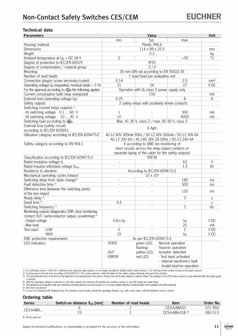
Technical dataParameters Value Unit
min. typ. max.Housing material Plastic PA6.6Dimensions 114 x 99 x 22.5 mmWeight 0.2 kgAmbient temperature at UB = DC 24 V 0 - +55 °CDegree of protection to IEC/EN 60529 IP20Degree of contamination / material group 2 / IIMounting 35 mm DIN rail according to EN 50022-35Number of read heads 1 read head per evaluation unitConnection (plug-in screw terminals/coded) 0.14 - 2.5 mm²Operating voltage UB (regulated, residual ripple < 5 %) 21 24 27 V DCFor the approval according to the following applies Operation with UL-class 2 power supply onlyCurrent consumption (with relay energized) 150 mAExternal fuse (operating voltage UB) 0.25 8 ASafety outputs 2 safety relays with positively driven contactsSwitching current (relay outputs) 1)
- At switching voltage 0.1 ... 60 V 1 - 300 mA- At switching voltage 10 ... 30 V 10 - 6000 mASwitching load according to Max. AC 30 V, class 2 / max. DC 60 V, class 2External fuse (safety circuit)according to IEC/EN 60269-1
6 AgG
Utilization category according to IEC/EN 60947-5-2 AC-12 60V 300mA 50Hz / DC-12 60V 300mA / DC-12 30V 6AAC-12 30V 6A / AC-140 30V 2A 50Hz / DC-13 24V 4A
Safety category according to EN 954-1 4 according to SIBE (on monitoring ofshort circuits across the relay output contacts or
separate laying of the cable for the safety outputs)Classification according to IEC/EN 60947-5-3 PDF-MRated insulation voltage Ui - - 63 VRated impulse withstand voltage Uimp - - 1.5 kVResilience to vibration According to IEC/EN 60947-5-2Mechanical operating cycles (relays) 10 x 106
Switching delay from state change2) - - 180 msFault detection time 3) - - 500 msDifference time (between the switching pointsof the two relays)
- - 120 ms
Ready delay 4) 3 sDwell time 5) 0.5 - - sSwitching frequency 7) - - 1 HzMonitoring outputs (diagnostics ERR, door monitoringcontact OUT, semiconductor output, p-switching) 6)
- Output voltage 0.8 x UB - UB V DC- Max load - - 20 mATest input LOW 0 - 2 V DC
HIGH 15 - UB V DCEMC protection requirements As per IEC/EN 60947-5-3LED indicators STATE green LED: Normal operation
flashing: Teach-in operationOUT yellow LED: Actuator detectedERROR red LED: - Test input activated
- Internal electronics fault- Invalid teach-in operation
1) If a switching current > 300 mA is switched once using the relay outputs, it is no longer possible to reliably switch small currents (< 10 mA) due to the contact erosion on the gold contacts.2) Corresponds to the risk time according to EN 60947-5-3. This is the maximum switch-off delay for the safety outputs following removal of the actuator.3) The fault detection time is the time for the detection of an internal fault in the device. At least one of the relay outputs is opened safely. The welding of one of the relay contacts is only detected after the safety guard
is opened.4) After the operating voltage is switched on, the relay outputs are switched off and the door auxiliary contact is set LOW during the ready delay.5) The dwell time of an actuator inside and outside the operating distance must be at least 0.5 s to ensure reliable detection of internal faults in the evaluation unit (self-monitoring).6) Not short circuit-proof7) In case of monitoring with feedback loop, the actuators must remain outside the operating distance, e.g. with a door open, until the feedback circuit is closed.
Ordering tableSeries Switch-on distance Sa0 [mm] Number of read heads Item Order No.
CES-A-ABA... 6 1 CES-A-ABA-01 071 85015 1 CES-A-ABA-01B 8) 083 513
8) No UL approval
12
Non-Contact Safety Switches CES/CEM
Subject to technical modifications; no responsibility is accepted for the accuracy of this information.
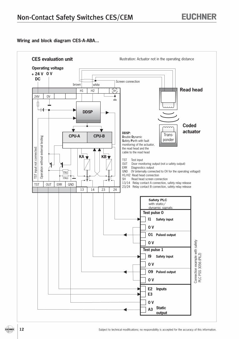
Wiring and block diagram CES-A-ABA...
24V
TST
TST
inpu
t not
con
nect
ed:
Oper
atio
n w
ithou
t ext
erna
l tes
ting
0V
OUT ERR GND
H1
10kΩ
10kΩ
H2
1413 23 24
SH
DDSP
CPU-A CPU-B
KA KB
whitebrownScreen connection
+ 24 VDC
0 VOperating voltage
DDSP:D DS P
ouble ynamicafety arth with fault
monitoring of the actuator,the read head and thecable to the read head
TST Test inputOUT Door monitoring output (not a safety output)ERR Diagnostics outputGND 0V (internally connected to OV for the operating voltage))H1/H2 Read head connectionSH Read head screen connection13/14 Relay contact A connection, safety relay release23/24 Relay contact B connection, safety relay release
CES evaluation unit
Read head
Codedactuator
Trans-ponder
O1 Pulsed output
Safety inputI1
Test pulse 0
0 V
0 V
E2E3
A3
Inputs
Staticoutput
O9 Pulsed output
Safety inputI9
Test pulse 1
0 V
0 V
Conn
ectio
n ex
ampl
e w
ith s
afet
yPL
C PS
S 30
56 (P
ILZ)
0 V
Safety PLCwith static/dynamic signals
Illustration: Actuator not in the operating distance

13
Non-Contact Safety Switches CES/CEM
Subject to technical modifications; no responsibility is accepted for the accuracy of this information.
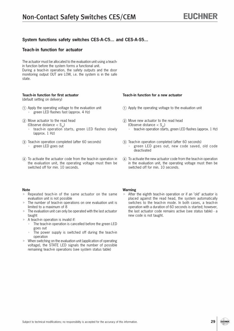
Teach-in function for actuatorThe actuator must be allocated to the evaluation unit using a teach-in function before the system forms a functional unit.During a teach-in operation, the safety outputs and the doormonitoring output are LOW, i.e. the system is in the safe state.
Teach-in function for first actuator(default setting on delivery)
Apply the operating voltage to the evaluation unit green LED flashes fast (approx. 4 Hz)
Move actuator to the read head(Observe distance < Sa0) teach-in operation starts, green LED flashes slowly
(approx. 1 Hz)
Teach-in operation completed (after 60 seconds) green LED goes out
To activate the actuator code from the teach-in operation inthe evaluation unit, the operating voltage must then beswitched off for min. 10 seconds.
Teach-in function for a new actuator
Apply the operating voltage to the evaluation unit
Move new actuator to the read head(Observe distance < Sa0) teach-in operation starts, green LED flashes (approx. 1 Hz)
Teach-in operation completed (after 60 seconds) green LED goes out, new code saved, old code
deactivated
To activate the new actuator code from the teach-in operationin the evaluation unit, the operating voltage must then beswitched off for min. 10 seconds.
Notes Repeated teach-in of the same actuator on the same
evaluation unit is not possible The number of teach-in operations on one evaluation unit is
limited to a maximum of 8 The evaluation unit can only be operated with the last actuator
taught A teach-in operation is invalid if:
The teach-in operation is cancelled before the greenflashing LED goes out
The power supply is switched off during the teach-inoperation
When switching on the evaluation unit (application of operatingvoltage), the STATE LED signals the number of possibleremaining teach-in operations (see system status table)
Warning After the eighth teach-in operation or if an "old" actuator is
placed against the actuator head, the system automaticallyswitches to the teach-in mode. In both cases, a teach-inoperation with a duration of 60 seconds is started; however,the last actuator code remains active (see system statustable) in the memory - a new code is not taught.
For this purpose, the opening of the safety guard can be simulatedby applying DC 24 V to the test input TST.The safety outputs are switched off, enabling testing of thecomplete safety circuit. The diagnostic output ERR on theevaluation unit is also set HIGH as a monitoring function.When the test input TST is reset, the evaluation unit resets thediagnostic output ERR to LOW, the red LED switches off and thesafety outputs are switched on again. This permits self-testing ofthe safety system without opening the safety guard.In the Manual start operating mode, the start button must bepressed again to start the system.
Function test (self-test)On electromechanical safety switches or magnetic switches, thefunction test can be performed by cyclically opening the safetyguard. From safety category 2, according to EN 60204-1 : 1997(sec. 9.4.2.4), a function test must be performed on the entiresafety system on start-up or after defined intervals.The testing of the internal function of the safety switch CES is notnecessary because the device monitors itself in real time. Wear onan output contact (relay output) is detected by the device at thelatest the next time the safety guard is opened. A short circuit in theoutput cable is not detected by the device. In addition, the entiresafety circuit can be tested without opening the safety guard.
System functions evaluation unit CES-A-ABA...
14
Non-Contact Safety Switches CES/CEM
Subject to technical modifications; no responsibility is accepted for the accuracy of this information.
Evaluation unit CES-A-AEA...
Housing for DIN rail mounting, IP 20 Relay output 2 or 4 read heads can be connected
Functional descriptionThe Coded Electronic Safety switch CES comprises threecomponents:
Coded actuator Read head Evaluation unit
Based on the concept of the safety switch CES-A-ABA..., theevaluation units described in this chapter have the option ofconnecting 1...2 or 1...4 read heads. As a result, up to four safetyguards can be monitored. The evaluation unit also has connectionterminals for a start button and for the feedback loop for monitoringpower contactors. The start button and the feedback loop aremonitored for short-circuits.The following settings can be made optionally using DIP switcheson the evaluation unit:
Number of read heads 1...2 or 1...4 Manual or automatic start Operation with or without feedback loop
The configuration of the entire system can be changed as oftenas required using a "teach-in operation". After appropriatepreparations (fitting a jumper to the evaluation unit), a new actuatorcan also be taught-in as often as required in service.
The non-contact safety switch CES-A-AEA... has a relatively largeoperating distance of 15 mm. Compared with mechanical safetyswitches, the assembly of the unit is much easier and the needfor precision in the door rails is also reduced considerably.Therefore the assembly and maintenance costs are much lower.The two-core connection cable to the evaluation unit is hard-wiredto the read head or can be plugged in using a round M8 plugconnector. In this way, the wiring work is reduced to an absoluteminimum.
The read heads are fastened to the fixed part of the safety guardand are each connected to the evaluation unit via a two-core screenedcable. The actuator fastened to the movable part of the safety guardis moved towards the read head by closing the door. When theswitch-on distance is reached, power is supplied to the actuator bythe inductive read head and data can be transferred.The bit pattern read is compared with the code saved in the evaluationunit. If the data match, the door monitoring output O1...O2 or O1...O4(semiconductor output) on the related read head is set HIGH. If alldata for all read heads activated match, the safety outputs (relayoutputs) are then enabled. The OUT LED illuminates.Due to the combination of dynamic polling of the actuators andthe redundant, diverse design of the safety electronics with thetwo safety outputs, the evaluation unit will enter the safe statewith every conceivable fault.
When a safety guard is opened, the safety outputs switch off thesafety circuit and the OUT LED goes out. The state of the safetyoutputs is monitored internally by positively driven NC contacts(relay output). Independent of the switching state of the safety circuit,the position of all safety doors can be polled via the outputs O1...O2or O1...O4.If an internal fault occurs in the evaluation unit, the safety circuit isswitched off, the diagnostic output (DIA) is set HIGH and the DIALED illuminates red.
The start button is also monitored. This is achieved by evaluatingthe falling edge of the start signal. In this way it is not possible fora signal continuously present on the input of the evaluation unit(e.g. stuck button contact) to result in the automatic start of thesystem.The evaluation unit provides the option of monitoring powercontactors connected in series.The evaluation unit can only be started with the feedback loopclosed. A welded contactor contact in the release path will thusbe detected when a start request is made.
The safety contacts on the new evaluation unit can switch switchingcurrents from 1 mA to 6 A. Since small currents can be switched,the user has the option of connecting the safety switch CES directlyto a safe control system. Safe control systems will becomeincreasingly important as technology progresses.
With a switching capacity of DC 24 V / 6 A or AC 230 V / 1.5 A,the evaluation unit can be connected directly to the majority ofpower contactors, without further coupling modules.
With its new safety switch CES, EUCHNER has introduced anintegrated solution on the market. With a single system, the usercan realize such applications as the monitoring of safety guards,wiring, evaluation and even the monitoring of externally connecteddevices. The user thus achieves maximum safety at a reasonablecost without the need for further equipment, e.g. emergency-stopswitchgear.
Due to the internal design of the device and the monitoring facilityfor the external connected devices, the non-contact safety switchCES-A-AEA... can be used for the highest safety requirements ofsafety category 4 according to EN 954-1 with approval from BGand SIBE Switzerland.
15
Non-Contact Safety Switches CES/CEM
Subject to technical modifications; no responsibility is accepted for the accuracy of this information.
Your advantages
Evaluation units for the connection of 1 ... 2 or 1 ... 4 read headsSelectable via DIP switches: Number of read heads (1...4) Manual or automatic start Operation with or without a feedback loop for monitoring power contactors
Monitored start button and feedback loop Short circuits are reliably detected
Evaluation unit teach-in function Teach-in of a new actuator using simple aids (fitting a jumper to the evaluation unit) Unlimited number of teach-in operations possible
Two redundant relay outputs (safety outputs) with internally monitored contacts, suitable for: Safety category 4 according to EN 954-1 (according to BG and SIBE)
Dynamic data transmission to the read head All faults (e.g. broken cable, short circuit, failure of the actuator) are reliably detected High safety due to dynamic performance
Suitable for connection to a safe control system with or without pulse signals
Several evaluation units can be connected in series Suitable for monitoring systems with several safety guards
Switching capacities DC 24 V / 6 A or AC 230 V / 1.5 A Direct connection to power contactor possible without extra coupling modules
Self-test without opening the safety guard
Monitoring output available Control system can poll the state of the safety guard
Fault diagnostics possible using LED indicator
Large operating distance and 15 mm with additional hysteresis Large mechanical tolerances possible for door guide
Approvals from BG, UL, SIBE

16
Non-Contact Safety Switches CES/CEM
Subject to technical modifications; no responsibility is accepted for the accuracy of this information.
Evaluation unit CES-A-AEA-02B
Housing for DIN rail mounting, IP 20 Relay output 2 read heads can be connected In combination with read head CES-A-L... and actuator CES-A-B..
Dimension drawing Switching characteristics2 safety outputs (relay outputs)2 door monitoring outputs (semiconductoroutputs, not safety outputs)
Notes on installationThe evaluation unit must be mounted in a controlcabinet with a minimum degree of protection ofIP 54. A snap-in element on the back of theevaluation unit is used for fastening to thestandard rail (35 mm DIN rail).
Safety precautions The evaluation unit has a redundant
switching design with self-monitoring. Thismeans that the safety system is still effectiveeven if a component fails.
The door monitoring outputs O1 ... O2 arenot fail-safe (not safety outputs)
To ensure safety, both safety outputs 13/14and 23/24 must always be evaluated.
Notes on the electrical connection All the electrical connections must either be isolated from the mains supply by
a safety transformer according to EN/IEC 61558 with limited output voltage inthe event of a fault, or by other equivalent isolation measures.
The connections H1a/H1b ... H2a/H2b are not short circuit-proof. If a common power supply is used, all the inductive and capacitive loads (e.g.
contactors) connected to the power supply must be connected to appropriateinterference suppression units.
45
99
114
Suitable for 35 mm DIN railaccording to EN 50022-35
13 14
23 24
24 V O1
13 14
23 24
24 V O1
24 V O2 24 V O2
Safety guard
closed open(all actuators (e.g. actuator 1 not
detected) in the operating distance)
Read head 1 Actuator 1 Read head 1

17
Non-Contact Safety Switches CES/CEM
Subject to technical modifications; no responsibility is accepted for the accuracy of this information.
Technical dataParameters Value Unit
min. typ. max.Housing material Plastic PA6.6Dimensions 114 x 99 x 45 mmWeight 0.25 kgAmbient temperature at UB = DC 24 V -20 - +55 °CAtmospheric humidity Max. 80 %, not condensingDegree of protection to IEC/EN 60529 IP20Degree of contamination / material group 2 / IIMounting 35 mm DIN rail according to EN 50022-35Number of read heads Max. 2 read heads per evaluation unitConnection (screw terminals) 0.14 - 2.5 mm²Operating voltage UB (regulated, residual ripple < 5 %) 21 24 27 V DCFor the approval according to the following applies Operation with UL-class 2 power supply onlyCurrent consumption IB (with relay energized) 6) - 220 270 mAExternal fuse (operating voltage) 0.4 - 8 ASafety outputs 2 safety relays with positively driven contactsSwitching current (relay outputs)- At switching voltage 1 ... 60 V AC/DC 1 1) - 300- At switching voltage 17 ... 30 V AC/DC 15 - 6000 mA- At switching voltage 17 ... 230 V AC 15 - 1500Switching load according to Max. AC 30 V, class 2 / max. DC 60 V, class 2External fuse (safety circuit)according to IEC/EN 60269-1 6 AgG
Utilization category according to IEC/EN 60947-5-1 AC-12 60V 300mA 50Hz / DC-12 60V 300mAAC-12 30V 6A / DC-12 30V 6A
AC-15 230V 1.5A 50Hz / DC-13 24V 1.2AClassification according to IEC/EN 60947-5-3 PDF-MSuitable for safety category according to EN 954-1 4Rated insulation voltage Ui 250 VRated impulse withstand voltage Uimp 4 kVResilience to vibration According to IEC/EN 60947-5-2Mechanical life (relays) 10 x 106
Switching delay from state change2)
- 2 activated actuators - - 290 ms- 1 activated actuator - - 210Fault detection time 3) - - 500 msSwitching frequency 5) - - 1 HzDifference time between the switchingpoints of the two relays - - 240 ms(for 2 activated actuators)Manual start operating mode- Duration of operation of start button 250 - - ms- Start button response delay - 200 300Current via feedback loop Y1/Y2 5 8 10 mAPermissible resistance via feedback loop - - 600 ΩReady delay 4) - 10 12 sMonitoring outputs (diagnostics DIA, enable O1...O2,semiconductor output, p-switching, short circuit-proof)- Output voltage 0.8 x UB - UB V DC- Max load - - 20 mAStart button input S, test input TST- Input voltage LOW 0 - 2 V DC
HIGH 15 - UB V DC- Input current HIGH 5 8 10 mAEMC protection requirements as per IEC/EN 60947-5-3
1) If a switching current > 300 mA in conjunction with a switching voltage > 15 V or an inductive or capacitive load is switched once using the relay outputs, it is no longer possible to reliably switch small currents(< 15 mA) due to the contact erosion on the gold contacts.
2) Corresponds to the risk time according to EN 60947-5-3. This is the maximum switch-off delay for the safety outputs following removal of the actuator.3) The fault detection time is the time for the detection of an internal fault in the device. At least one of the relay outputs is opened safely. The welding of one of the relay contacts is only detected after the safety guard
is opened.4) After the operating voltage is switched on, the relay outputs are switched off and the monitoring outputs are set LOW during the ready delay. For the visual indication of the delay, the green STATE LED flashes at
a frequency of approx. 15 Hz.5) In case of monitoring with feedback loop, the actuators must remain outside the operating distance, e.g. with a door open, until the feedback circuit is closed.6) Without taking into account the load currents on the monitoring outputs.
Ordering tableSeries Safety category Number of read heads Item Order No.CES-A-AEA... 4 2 CES-A-AEA-02B 092 560

18
Non-Contact Safety Switches CES/CEM
Subject to technical modifications; no responsibility is accepted for the accuracy of this information.
Evaluation unit CES-A-AEA-04B
Housing for DIN rail mounting, IP 20 Relay output 4 read heads can be connected In combination with read head CES-A-L... and actuator CES-A-B..
Dimension drawing Switching characteristics2 safety outputs (relay outputs)4 door monitoring outputs (semiconductoroutputs, not safety outputs)
Notes on installationThe evaluation unit must be mounted in a controlcabinet with a minimum degree of protection ofIP 54. A snap-in element on the back of theevaluation unit is used for fastening to thestandard rail (35 mm DIN rail).
Safety precautions The evaluation unit has a redundant
switching design with self-monitoring. Thismeans that the safety system is still effectiveeven if a component fails.
The door monitoring outputs O1 ... O4 arenot fail-safe (not safety outputs)
To ensure safety, both safety outputs 13/14and 23/24 must always be evaluated.
Notes on the electrical connection All the electrical connections must either be isolated from the mains supply by
a safety transformer according to EN/IEC 61558 with limited output voltage inthe event of a fault, or by other equivalent isolation measures.
The connections H1a/H1b ... H4a/H4b are not short circuit-proof. If a common power supply is used, all the inductive and capacitive loads (e.g.
contactors) connected to the power supply must be connected to appropriateinterference suppression units.
45
99
114
Suitable for 35 mm DIN railaccording to EN 50022-35
13 14
23 24
24 V O1
13 14
23 24
24 V O1
24 V O2 24 V O2
24 V O3 24 V O3
24 V O4 24 V O4
Safety guard
closed open(all actuators (e.g. actuator 1 not
detected) in the operating distance)
Read head 1 Actuator 1 Read head 1

19
Non-Contact Safety Switches CES/CEM
Subject to technical modifications; no responsibility is accepted for the accuracy of this information.
Technical dataParameters Value Unit
min. typ. max.Housing material Plastic PA6.6Dimensions 114 x 99 x 45 mmWeight 0.25 kgAmbient temperature at UB = DC 24 V -20 - +55 °CAtmospheric humidity Max. 80 %, not condensingDegree of protection to IEC/EN 60529 IP20Degree of contamination / material group 2 / IIMounting 35 mm DIN rail according to EN 50022-35Number of read heads Max. 4 read heads per evaluation unitConnection (screw terminals) 0.14 - 2.5 mm²Operating voltage UB (regulated, residual ripple < 5 %) 21 24 27 V DCFor the approval according to the following applies Operation with UL-class 2 power supply onlyCurrent consumption IB (with relay energized) 6) - 220 270 mAExternal fuse (operating voltage) 0.4 - 8 ASafety outputs 2 safety relays with positively driven contactsSwitching current (relay outputs)- At switching voltage 1 ... 60 V AC/DC 1 1) - 300- At switching voltage 17 ... 30 V AC/DC 15 - 6000 mA- At switching voltage 17 ... 230 V AC 15 - 1500Switching load according to Max. AC 30 V, class 2 / max. DC 60 V, class 2External fuse (safety circuit)according to IEC/EN 60269-1 6 AgG
Utilization category according to IEC/EN 60947-5-1 AC-12 60V 300mA 50Hz / DC-12 60V 300mAAC-12 30V 6A / DC-12 30V 6A
AC-15 230V 1.5A 50Hz / DC-13 24V 1.2AClassification according to IEC/EN 60947-5-3 PDF-MSuitable for safety category according to EN 954-1 4Rated insulation voltage Ui 250 VRated impulse withstand voltage Uimp 4 kVResilience to vibration According to IEC/EN 60947-5-2Mechanical life (relays) 10 x 106
Switching delay from state change2)
- 4 activated actuators - - 450- 3 activated actuators - - 370 ms- 2 activated actuators - - 290- 1 activated actuator - - 210Fault detection time 3) - - 500 msSwitching frequency 5) - - 1 HzDifference time between the switchingpoints of the two relays - - 400 ms(for 4 activated actuators)Manual start operating mode- Duration of operation of start button 250 - - ms- Start button response delay - 200 300Current via feedback loop Y1/Y2 5 8 10 mAPermissible resistance via feedback loop - - 600 ΩReady delay 4) - 10 12 sMonitoring outputs (diagnostics DIA, enable O1...O4,semiconductor output, p-switching, short circuit-proof)- Output voltage 0.8 x UB - UB V DC- Max load - - 20 mAStart button input S, test input TST- Input voltage LOW 0 - 2 V DC
HIGH 15 - UB V DC- Input current HIGH 5 8 10 mAEMC protection requirements as per IEC/EN 60947-5-3
1) If a switching current > 300 mA in conjunction with a switching voltage > 15 V or an inductive or capacitive load is switched once using the relay outputs, it is no longer possible to reliably switch small currents(< 15 mA) due to the contact erosion on the gold contacts.
2) Corresponds to the risk time according to EN 60947-5-3. This is the maximum switch-off delay for the safety outputs following removal of the actuator.3) The fault detection time is the time for the detection of an internal fault in the device. At least one of the relay outputs is opened safely. The welding of one of the relay contacts is only detected after the safety guard
is opened.4) After the operating voltage is switched on, the relay outputs are switched off and the monitoring outputs are set LOW during the ready delay. For the visual indication of the delay, the green STATE LED flashes at
a frequency of approx. 15 Hz.5) In case of monitoring with feedback loop, the actuators must remain outside the operating distance, e.g. with a door open, until the feedback circuit is closed.6) Without taking into account the load currents on the monitoring outputs.
Ordering tableSeries Safety category Number of read heads Item Order No.CES-A-AEA... 4 4 CES-A-AEA-04B 072 000

20
Non-Contact Safety Switches CES/CEM
Subject to technical modifications; no responsibility is accepted for the accuracy of this information.
Activation of theteach-in operationwith bridges onJ1, J2
+24V+24V
Contactor Y
Contactor X
~
~
M
24V
+24V+24V
Startbutton
Semiconductor monitoring outputs
Feed
back
loop
M
Trans-ponder
Trans-ponder
Kopf 1 Kopf 2 Read head
Codedactuator
Trans-ponder
Trans-ponder
Head 1 Head 2
A B
+ 24 VDC
0 V
Operatingvoltage
UB
TST
0V
S
H1a H2aH1b H2bSH1 SH2
DIA 141323 Y124 Y2
DemodulatorFilter
VerstärkerKomparator
KAKB
Kopf - HF - Multiplexer( 1 aus 4 )
J2J1
O1 O2
DemodulatorFilter
AmplifierComparator
Head selection
+24 VKAKB
CPU-A(Typ 1)
CPU-A
(Type 1)
Head - HF - Multiplexer( 1 of 2 )
CPU-B
CPU-B
LEDSTATE
OUT
DIA
CPU-A
CPU-A
StartStart
CPU-B(Typ 2)
CPU-B
(Type 2)
STA TE O UT DIA
DIP switches
+UB, 0VJ1,J2
H1a,H1b..H2a,H2bSH1,SH2
TSTO1...O2
DIA13,1423,24Y1,Y2
S
Power supplyBridges for teach-in operationConnection, read heads 1...2ScreenTest inputSemiconductor monitoring outputsDiagnostics outputRelay contact A connection, safety relay release
Feedback loopConnection start button
Relay contact B connection, safety relay releaseIllustration: opensafety circuit
YS
H2H1
ON1
25
6
Wiring and block diagram CES-A-AEA-02B

21
Non-Contact Safety Switches CES/CEM
Subject to technical modifications; no responsibility is accepted for the accuracy of this information.
+24V+24V ~
24V
~~~
M
0 V
+++ 442422 VVVVAKAAKAKAKAKAKAKAKAKAKAKKAKKBKBKBKBKBKBKBKBKBKBKBKB
EEEELELLL DDDDDTTTSTSS TTATAATATTTATT EEEE
UUUOUOOO TTTUTUUTU
IDDD AAAA
Start
SSTTAAA TTTA TT EEE OOOUUTTT DDDIIAAA
+UB, 0V,
J1,J2
H1a,H1b..H4a,H4b
SH1,SH2,SH3,SH4
TST
O1..O4
DIA
13,14
23,24
Y1,Y2
S
YYYYYYYYYYYY
SSSSSSSSSSSSSSSSSSSSSSSSSSSSSSSS
HHHHHHHH4444444444444
HHHHHHHH333333333333333333333333
HHHHHHHH222222222222222
HHHHHHHH1111
ON
ON
1122
3344
5566
Semiconductor monitoring outputs
Contactor Y
Contactor X
Start
button
Feedback lo
op
H d l tiHead selectionHead selectionHead selection
CPU-A
(type 1)
BBB-BU-UUPUPPCPCCC
BBB-BU-UUPUPPCPCCC
AAA-A-U-UUPPPCCCC
AAA-A-U-UUPPPCCCC
CPU-B
(type 2)
DDDDIIPPP ssswwwwiittccchhh
Power supply
Jumper for teach-in operation
Connection for read heads 1..4
Screen
Testinput
Semiconductor monitoring outputs
Diagnostics output
Connection for relay contact B, safety relay enable
Feedback loop
Start button connection
Connection for relay contact A, safety relay enable
Illustration: normally closed
safety circuit
Activation of the
teach-in operation with
jumper
on J1, J2
Read heads
Codedactuators
DC
+ 24 V
Operating
voltage
Wiring and block diagram CES-A-AEA-04B

22
Non-Contact Safety Switches CES/CEM
Subject to technical modifications; no responsibility is accepted for the accuracy of this information.
Setup procedureDuring setup, the parameters are set in the evaluation unit by the user using a teach-in operation (number of connected read heads,assignment of the actuators to the read heads, with or without automatic start, with or without feedback loop). During this process theread heads are activated.These configuration parameters are saved in the non-volatile memory in the evaluation unit.
To trigger a teach-in operation, the user must perform the following actions in the stipulated order:
Prepare for teach-in operation Switch off power supply UB Fit a jumper between terminals J1 and J2
Set required configuration on DIP switches
Switch marking Slider position left (OFF) Slider position right (ON)1 No read head connected to terminals Read head connected to terminals
H1a, H1b, SH1 H1a, H1b, SH12 No read head connected to terminals Read head connected to terminals
H2a, H2b, SH2 H2a, H2b, SH23 No read head connected to terminals Read head connected to terminals
H3a, H3b, SH3 H3a, H3b, SH34 No read head connected to terminals Read head connected to terminals
H4a, H4b, SH4 H4a, H4b, SH45 Automatic start Manual start
(No start button connected) (Start button connected)6 No feedback loop connected Feedback loop connected
Set required configuration on machine Close all doors to be monitored (the actuators must be in the operating distance of the related read head) For Manual start operating mode: connect terminal S to 24 V (or keep start button pressed) For With feedback loop operating mode: keep feedback loop closed
Start teach-in operation Switch on operating voltage Wait for self-test (STATE LED flashes for approx. 10 seconds at 15 Hz) Teach-in operation starts (STATE LED flashes at approx. 1 Hz) Wait for acknowledgement of the teach-in operation (STATE LED goes out after approx. 10 seconds)
End teach-in operation Switch off operating voltage for at least 10 seconds Remove jumper between J1 and J2 For Manual start operating mode: connect start button to terminal S For With feedback loop operating mode: connect feedback loop Switch on operating voltage Wait for self-test (STATE LED flashes for approx. 10 seconds at 15 Hz)
Check all safety guards for effectiveness
NoteDuring the teach-in operation the following conditions must be met:
There must be no state change, e.g. opening a safety door or closing a further safety door The power supply must not be switched off
If these conditions are not met, the evaluation unit switches to the safe fault state (diagnostics LED illuminates) and signals thisoperating fault with the STATE LED by 3 short flashes that are repeated every second. The teach-in operation must be repeated.
Warning The number of teach-in operations is unlimited. The evaluation unit can be re-configured as often as required. Actuators cannot be interchanged without a renewed teach-in operation. An actuator that has not been subjected to teach-in will not be detected by the related read head. Even if only one new actuator needs to be taught, a complete new teach-in operation must be carried out as described in the
section "Setup procedure". Do not change DIP switches during operation.
System functions evaluation unit CES-A-AEA...

23
Non-Contact Safety Switches CES/CEM
Subject to technical modifications; no responsibility is accepted for the accuracy of this information.
Function test CES-A-AEA... (self-test)On electromechanical safety switches or magnetic switches, the function test can be performed by cyclically opening the safety guard.From safety category 2, according to IEC/EN 60204-1 : 1997 (sec. 9.4.2.4), a function test must be performed on the entire safetysystem on start-up or after defined intervals.The testing of the internal function of the safety switch CES is not necessary because the device monitors itself in real time. Wear onan output contact (relay output) is detected by the device at the latest the next time the safety guard is opened. A short circuit in theoutput cable is not detected by the device.In addition, the entire safety circuit can be tested without opening the safety guard. For this purpose the opening of the safety guardcan be simulated by applying DC 24 V to the test input.The safety outputs are switched off, enabling testing of the complete safety circuit. The diagnostic output DIA of the evaluation unit isalso set HIGH as a monitoring function.When the test input is reset, the evaluation unit resets the diagnostic output DIA to LOW, the red LED switches off and normal operationcontinues. This permits self-testing of the safety system without opening the safety guard.
LED indicatorsLED labels LED color Significance
STATE Green State display (multifunction display using flashing modes)OUT Yellow Safety circuit closedDIA Red Operating fault,
external fault (fault in the feedback loop)or internal device fault
TST input activated (function test active)
System status table CES-A-AEA-04BSTATE LED (green) OUT LED (yellow) DIA LED (red) State
SetupFlashes continuously Off Off Initial setup after delivery without jumper connected
at approx. 4 Hz to J1, J2Flashes at approx. 1 Hz Off Off Teach-in operation
Off Off Off Acknowledgement of completion of teach-in operationNormal operation
Flashes Off Off Self-test, duration approx. 10 seconds, is performedat approx. 15 Hz after the application of the operating voltage UB
On Off Off Normal operation, not all monitored doors are closedOn On Off Normal operation, all monitored doors are closed
(After pressing the start button, for Manual startoperating mode)
Function testOn Off On Function test active (TST input = 24 V)
Fault displayOff Off On Component failure inside the device or actuator in
the operating distance for less than 0.5 s oractuator CES-A-BMB in the inadmissible range
Operating fault3 flashes repeated Off On Configuration fault:
after 1 s Teach-in operation must be performed againPossible causes:- State change during the teach-in operation- None of the DIP switches in ON position- DIP switch setting and
connected configuration did not match duringteach-in operation
- DIP switch setting has been changed withoutteach-in operation
- The teach-in jumper (J1, J2) was fitted with powersupply switched on
- Connected feedback loop (Y1,Y2) present,although a feedback loop was not present duringteach-in
- 24 V signal present at the start button input (S)although teach-in was performed with "Automaticstart" operating mode
4 flashes repeated after 1 s Off On Fault in feedback loop

24
Non-Contact Safety Switches CES/CEM
Subject to technical modifications; no responsibility is accepted for the accuracy of this information.
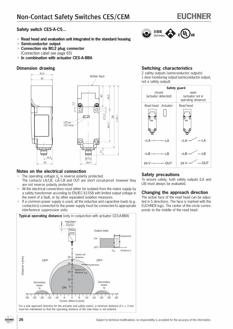
Non-contact safety switches CES-A-C5...
Standard housing according to IEC/EN 60947-5-2, IP 67
Read head and evaluation unit integrated in thestandard housing
Semiconductor output Connection of the safety circuit using M12 plug
connector
Functional descriptionThe Coded Electronic Safety switch CES comprises twocomponents:
Coded actuator
Evaluation unit / read head
The evaluation unit described in this chapter is integrated with theread head in a standard housing according to IEC/EN 60947-5-2.
Thanks to the high degree of protection IP67, this switch can beused directly on the safety guard in a very harsh environment.Semiconductor technology allows for a compact design of theevaluation unit and wear-free switching with a theoretically unlimitednumber of operating cycles.The information from the coded actuator is read by the evaluationunit and processed at the same point. The transfer of static signals(information on whether door open or closed) to the higher levelswitchgear permits the use of connecting cables up to 300 mlong with the system.Serial wiring, i.e. the cascading of several evaluation units, ispossible. In this way, you can implement decentralized wiringconcepts with the safety switch CES.Specifically, the major advantage of the system is that thepositioning of the evaluation unit directly at the safety guard savesspace in the control cabinet.The system operator can read the current state of the safetyswitch on the two LED indicators (one with double function). If theactuator is in the operating distance, the OUT LED illuminatesyellow. Even a possible fault in the evaluation unit is displayed bya red LED. In service, the safety switch connected with an M12plug connector can be replaced in seconds. The required approachdirection can also be set quickly on the compact housing. Aftertwo fastening screws have been undone, the active face of theread head can be set in 5 different positions.
The non-contact safety switch CES-A-C5E... has a relatively largeoperating distance of 20 mm. Compared with mechanical safetyswitches, the assembly of the unit is much easier and the needfor precision in the door rails is also reduced considerably.Therefore the assembly and maintenance costs are much lower.
The safety switch with integrated evaluation unit and read head isfastened to the fixed part of the safety guard.The actuator attached to the movable part of the safety guard ismoved towards the read head fitted in the safety switch by closingthe doors. When the switch-on distance is reached, power issupplied to the actuator by the inductive read head and data canbe transferred.The bit pattern read is compared with the code saved in theevaluation unit; if the data matches, the safety outputs(semiconductor outputs) and the door monitoring output(semiconductor output) are also set HIGH.Due to the combination of dynamic polling of the actuator and theredundant, diverse design of the safety electronics with the twofeedback safety outputs, the evaluation unit will enter the safestate with every detectable fault.When the safety guard is opened, the safety outputs switch offthe safety circuit and the door monitoring output (OUT) is switchedLOW. The state of the safety outputs is monitored internally bytwo microprocessors.On an internal fault in the evaluation unit, the safety circuit isswitched off and the OUT/ERROR LED illuminates red.The evaluation unit has a redundant switching design with self-monitoring. This means that the safety system is still effectiveeven if a component fails.
25
Non-Contact Safety Switches CES/CEM
Subject to technical modifications; no responsibility is accepted for the accuracy of this information.
Evaluation unit teach-in function New actuator teach-in can be performed without any other equipment The number of teach-in operations is restricted to eight to provide security against tampering
Safety switch in standard housing according to IEC/EN 60947-5-2
Two redundant design semiconductor outputs (safety outputs) with internal monitoring: CES-A-C5E-01: Safety category 3 according to EN 954-1 (according to BG and SIBE Switzerland) CES-A-C5H-01: Safety category 4 according to EN 954-1 (according to BG and SIBE Switzerland)
Read head and evaluation unit form a compact unit Reduction of wiring faults during setup
Relocation of the evaluation unit from the control cabinet to the system Space-saving in the control cabinet Decentralized wiring concept possible
Connection via M12 plug connector Prevention of wiring faults
Easy adjustment of the read head in 5 approach directions
Short circuit-proof monitoring and safety outputs High reliability
Large operating distance of 20 mm with additional hysteresis Large mechanical tolerances possible for door guide
Small design of the actuator (cube-shaped)
Flush installation in door panel is possible
Approval from BG
Your advantages
26
Non-Contact Safety Switches CES/CEM
Subject to technical modifications; no responsibility is accepted for the accuracy of this information.
30
M12x1
±0,
1
±0,1
13
118
45,540
∅ 5
,3
60
7,3
( 131
)
16,5
40,5
30
40
LED gnLED rd/ye
Switching characteristics2 safety outputs (semiconductor outputs)1 door monitoring output (semiconductor output,not a safety output)
Safety precautionsTo ensure safety, both safety outputs (LA andLB) must always be evaluated.
Changing the approach directionThe active face of the read head can be adjus-ted in 5 directions. The face is marked with theEUCHNER logo. The center of the circle corres-ponds to the middle of the read head.
Dimension drawing
Safety switch CES-A-C5...
Read head and evaluation unit integrated in the standard housing Semiconductor output Connection via M12 plug connector
(Connection cabel see page 65) In combination with actuator CES-A-BBA
Notes on the electrical connection The operating voltage UB is reverse polarity protected.
The contacts LA/LB, -LA/-LB and OUT are short circuit-proof, however theyare not reverse polarity protected
All the electrical connections must either be isolated from the mains supply bya safety transformer according to EN/IEC 61558 with limited output voltage inthe event of a fault, or by other equivalent isolation measures.
If a common power supply is used, all the inductive and capacitive loads (e.g.contactors) connected to the power supply must be connected to appropriateinterference suppression units.
Safety guard
Read head Actuator Read head
closed open(actuator detected) (actuator not in
operating distance)
Typical operating distance (only in conjunction with actuator CES-A-BBA)
For a side approach direction for the actuator and safety switch, a minimum distance of s = 3 mmmust be maintained so that the operating distance of the side lobes is not entered.
+LA LA
+LB LB
24 V OUT
+LA LA
+LB LB
24 V OUT
Secondarybeam
N
-30 -10-15 -5 0Centre offset m [mm]
Dis
tanc
e s
[mm
]
OFF
ON
Actuator
Readhead
s
m
Hysteresis
Switch-ondistance Sa0
ON
OFF
Hysteresis
Distance sSa0
Output state
Switch-offdistance
OFF
-20-25 -5 -25-20 -30-15-10
5
10
15
20
25
Secondarybeam
N
Active face

27
Non-Contact Safety Switches CES/CEM
Subject to technical modifications; no responsibility is accepted for the accuracy of this information.
Technical dataParameters Value Unit
min. typ. max.Housing material Plastic PBT V0 GF30Dimensions According to EN 60 947-5-2Weight 0.4 kgAmbient temperature at UB = DC 24 V -20 - +55 °CDegree of protection to IEC/EN 60529 IP67Safety class according to IEC/EN 61558 IIIInstallation position AnyConnection type M12 plug connector, 8-pin, screen can be appliedOperating voltage UB (reverse polarity protected,regulated, residual ripple < 5 %)
18 24 27 V DC
For the approval according to the following applies Operation with UL-class 2 power supply onlyCurrent consumption 80 mASwitching load according to DC 24 V, class 2External fuse (operating voltage) 0.25 - 8 APower supply for load U(+LA) / U(+LB) 18 - 27 V DCSafety outputs (LA / LB, 2 semiconductoroutputs, p-switching, short circuit-proof,electrically decoupled)- Output voltage U(LA) / U(LB) 1)
HIGH U(LA) U(+LA) - 1.5 - U(+LA) HIGH U(LB) U(+LB) - 1.5 - U(+LB) V DC LOW U(LA) / U(LB) 0 - 1Switching current per safety output 1 - 400 mAExternal fuse U(+LA) / U(+LB),Safety circuit
400 mA medium slow-blow
Utilization category according to IEC/EN 60947-5-2 DC-13 24V 400 mAClassification according to IEC/EN 60947-5-3 PDF-MDoor monitoring contact (OUT, semiconductor output,p-switching, short circuit-proof)- Output voltage 0.8 x UB - UB V DC- Max load - - 20 mARated insulation voltage Ui - - 30 VRated impulse withstand voltage Uimp - - 1.5 kVResilience to vibration According to IEC/EN 60947-5-2Switching delay from state change 2) - - 180 msFault detection time 3) - - 500 msDifference time between the two safety outputs - - 120 msReady delay 4) 3 sDwell time 5) 0.5 - - sSwitching frequency - - 1 HzOperating distance for center offset = 0 6)
Switch-on distance sa0 18 20 -Switching hysteresis 2 3 - mmSafe switch-off distance sar - - 40Mounting distance between two read headsor two actuators 80 - - mm
EMC protection requirements As per IEC/EN 60947-5-3LED indicators STATE green LED: Normal operation
flashing: Teach-in operationOUT/ERROR yellow LED: Actuator detectedOUT/ERROR red LED: - Test input activated
- Internal electronics fault- Invalid teach-in operation
1) Values at a switching current of 50 mA without taking into account the cable lengths.2) Corresponds to the risk time according to EN 60947-5-3. This is the maximum switch-off delay for the safety outputs following removal of the actuator.3) The fault detection time is the time for the detection of an internal fault in the device. At least one of the semiconductor outputs is switched off safely.4) After the operating voltage is switched on, the semiconductor outputs are switched off and the monitoring outputs are set LOW during the ready delay.5) The dwell time of an actuator inside and outside the operating distance must be at least 0.5 s to ensure reliable detection of internal faults in the evaluation unit (self-monitoring).6) The values apply for surface installation of the actuator.
Ordering tableSeries Switch-on distance sa0 [mm] Safety category Item Order No.
CES-A-C5... 20 3 CES-A-C5E-01 077 7504 CES-A-C5H-01 091 458

28
Non-Contact Safety Switches CES/CEM
Subject to technical modifications; no responsibility is accepted for the accuracy of this information.
12345678
0V+ U
LALB
OUT+LA-LAB+LB
B
I1
O1
0 V
0 V
E2
I9
O9
0 V
0 V
0 V
OUT
DC +24 V
+LB
-LAB
LB
+LA
LA
+ U
0V
(RD)
(BU)
(YE)
(PK)
(GN)
(GY)
(BN)
(WH)
+LA
LA
R
B
-LAB
+
-
Trans-
ponder
Pin assignment:
Common ground for output A and B
Load A
Pin Core colorWH/whiteBN/brownGN/greenYE/yellowGY/grayPK/pinkBU/blueRD/red
Function
Coded
actuator
Read head with
evaluation unit
CES-A-C5...
Housing:
NG 5
118 x 40 x 40 mm
Connection:
M 12x1
8-pin, screened
Read head
Safety input
Pulsed output
Input
Safety input
Pulsed output
Output circuit:
Screen spring
The screen on the connection cableis connected internally to the screen spring on the housing.
Safety PLC
with static /
dynamic signals
Co
nn
ectio
n e
xa
mp
le w
ith
sa
fety
PL
C P
SS
30
56
(P
ILZ
)
Power
supply
for load A
Test pulse 0
Test pulse 1
8
3
5
7
4
21
6
Wiring and block diagram CES-A-C5...
View on the safety switch'splug
Illustration: Actuator not in the operating distance
29
Non-Contact Safety Switches CES/CEM
Subject to technical modifications; no responsibility is accepted for the accuracy of this information.
Teach-in function for actuator
The actuator must be allocated to the evaluation unit using a teach-in function before the system forms a functional unit.During a teach-in operation, the safety outputs and the doormonitoring output OUT are LOW, i.e. the system is in the safestate.
Teach-in function for first actuator(default setting on delivery)
Apply the operating voltage to the evaluation unit green LED flashes fast (approx. 4 Hz)
Move actuator to the read head(Observe distance < Sa0) teach-in operation starts, green LED flashes slowly
(approx. 1 Hz)
Teach-in operation completed (after 60 seconds) green LED goes out
To activate the actuator code from the teach-in operation inthe evaluation unit, the operating voltage must then beswitched off for min. 10 seconds.
Teach-in function for a new actuator
Apply the operating voltage to the evaluation unit
Move new actuator to the read head(Observe distance < Sa0) teach-in operation starts, green LED flashes (approx. 1 Hz)
Teach-in operation completed (after 60 seconds) green LED goes out, new code saved, old code
deactivated
To activate the new actuator code from the teach-in operationin the evaluation unit, the operating voltage must then beswitched off for min. 10 seconds.
Note Repeated teach-in of the same actuator on the same
evaluation unit is not possible The number of teach-in operations on one evaluation unit is
limited to a maximum of 8 The evaluation unit can only be operated with the last actuator
taught A teach-in operation is invalid if:
The teach-in operation is cancelled before the green LEDgoes out
The power supply is switched off during the teach-inoperation
When switching on the evaluation unit (application of operatingvoltage), the STATE LED signals the number of possibleremaining teach-in operations (see system status table)
Warning After the eighth teach-in operation or if an "old" actuator is
placed against the read head, the system automaticallyswitches to the teach-in mode. In both cases, a teach-inoperation with a duration of 60 seconds is started; however,the last actuator code remains active (see status table) - anew code is not taught.
System functions safety switches CES-A-C5... and CES-A-S5...

30
Non-Contact Safety Switches CES/CEM
Subject to technical modifications; no responsibility is accepted for the accuracy of this information.
Non-contact safety switches CES-A-S5...
Standard housing according to IEC/EN 60947-5-2,IP 67
Read head and evaluation unit integrated in thestandard housing
Semiconductor output Connection of the safety circuit using M12 plug
connector
Functional descriptionThe non-contact safety switch CES-A-S5H-01 combines two diffe-rent functions in one device:
Safety function
Identification function/position sensor
The safety function is the same as the functionality of the EUCHNERsafety switch CES-A-C5H-01 in the compact housing withsemiconductor output employing proven transponder technology:
Two safety semiconductor outputs LA and LB signal the presenceof a safety actuator and the closed position of the safety guard.
Every safety actuator is unique, the actuator can be used withall non-contact EUCHNER safety switches CES.
The identification function or position sensor in the device islargely identical to the EUCHNER identification system CIS3 and itsproven read head CIT3PL:
Using 14 different position actuators, 14 different positions ofa moving guard can be detected.
Every position actuator has a number that is saved in the integratedtransponder.For ease of use during installation and maintenance of the system,laser marking is used to apply the related transponder number inplain text to the housing of the position actuators. In addition, forclear differentiation between the actuators, different housing colorsare used for safety actuators (red) and position actuators (green).
The related transponder number 2, 3, 4…9, A, B …F for the positionactuator (in total 14 different dogs) is signaled to the higher levelcontrol system using the 4 semiconductor outputs D0, D1, D2, D3in binary code. These data outputs have no safety function.The position actuators cannot switch the safety outputs LA and LB.The safety outputs on the switch are only activated by the currentsafety actuator.The safety actuator is always signaled on the data outputs as number1 (0001)(The no. 1 on the 4 data outputs corresponds to the OUT output onthe EUCHNER safety switches CES-A-C5…).Using the binary code 0000 it is signaled that neither the safetyactuators nor a position actuator is within the operating distance ofthe read head (see pulse diagram on page 35).
Using 4 yellow LEDs (D0, D1, D2, D3) on the safety switch, the dataoutputs currently set are indicated visually based on the actuatorswithin the operating distance.
The non-contact switch CES-A-S5H-01 has a large operating distanceof 20 mm for the safety actuators and the position actuators.Compared to mechanical safety switches, significantly less effort isrequired here for the adjustment of the door guide.
The maximum relative speed of the position actuator towards theread head is extremely high and is max. 2.0 m/sec. To enable thehigher level control system to reliably detect the signals read, theposition actuators are "stretched" electronically, i.e. the signals remainset on the data outputs D0, D1, D2, D3 for an additional delay ofapprox. 0.2 seconds.
With conventional transponder systems, undefined states occur ifthe transponder is at the edge of the operating distance. Thesestates manifest themselves in the form of irregular state changesand the flickering of the optical indicators.
The EUCHNER safety switches CES are equipped with a specialinternal circuit. This circuit provides exact operating points for theapproach and removal (with shutdown hysteresis) of the actuators(transponder) with the following advantages:
Reliable operation is ensured at all permissible movementspeeds
Sporadic failure to detect the transponder or the reading ofincorrect data is effectively prevented.
If the actuator is positioned exactly at the limit of the switch-ondistance, vibrations at the safety guard will not cause the machineto stop unintentionally.
A possible application example for the safety switch CES-A-S5H-01is the monitoring of automatic roller doors.Instead of fastening, adjusting and wiring several mechanical positionswitches as well as two electromechanical safety switches, it isonly necessary to fasten the safety switch CES-A-S5H-01 (safetycategory 4) to the stationary part of the safety guard and connect itusing a 12-pin plug connector.The position actuators (dogs) are mounted at the necessary positionsof the moving part of the safety guard. The safety actuator is fittedwith the safety guard in the closed position. As a result the rollerdoor can be closed at high speed (max. 2.0 m/s). On the detectionof the last position actuator, the number of the actuator is forwardedover the data outputs to the control system and the roller doorspeed reduced. When the safety guard (roller door) is in the closedposition, the safety actuator is detected, the safety outputs on theCES-A-S5H-01 switched and the system can be started.
The fastening and wiring effort for the mechanical position switchesis reduced to zero.In addition, all further advantages of non-contact transpondertechnology such as freedom from wear, large operating distancewith highly tolerant door guiding.

31
Non-Contact Safety Switches CES/CEM
Subject to technical modifications; no responsibility is accepted for the accuracy of this information.
Safety and identification functions integrated into one switch
Detection of 14 different position actuators
High approach speed (2.0 m/s) of the position actuators
Safety switch in standard housing according to EN 60947-5-2 Read head and evaluation unit form a compact unit
Relocation of the evaluation unit from the control cabinet to the system Space-saving in the control cabinet Decentralized wiring concept possible
Two redundant design semiconductor outputs (safety outputs) with internal monitoring
Connection using 12-pin plug connector Reduction of wiring faults during setup
Safety category 4 according to EN 954-1
BG approval (approval pending)
Your advantages

32
Non-Contact Safety Switches CES/CEM
Subject to technical modifications; no responsibility is accepted for the accuracy of this information.
Switching characteristics2 safety outputs (semiconductor outputs)4 data outputs for actuator number (semiconduc-tor outputs, not safety output)
Notes on the electrical connection The operating voltage UB is reverse polarity
protected. The data outputs D0, D1, D2, D3 have no
safety function. Both safety outputs LA and LB must be
evaluated. The safety outputs LA and LB as well as the
data outputs D0, D1, D2, D3 are shortcircuit-proof.
All the electrical connections must either beisolated from the mains supply by a safetytransformer according to IEC/EN 61558with limited output voltage in the event of afault, or by other equivalent isolationmeasures.
If a common power supply is used, all theinductive and capacitive loads (e.g. contac-tors) connected to the power supply mustbe connected to appropriate interferencesuppression units.
Changing the approach directionThe active face of the read head can be adjustedin 5 directions. The face is marked with theEUCHNER logo. The center of the circlecorresponds to the middle of the read head.
Dimension drawing
Active face
Safety guard
Read head Safety Read headactuator
Safety Switch CES-A-S5H-01
Safety and identification functions Read head and evaluation unit integrated in the standard housing Semiconductor output Connection using 12-pin plug connector (Plug connector see page 66) In combination with safety actuator CES-A-BBA and position
actuator CES-A-NBA-.
closed open(actuator detected) (actuator not in the
operating distance)
Typical operating distance (for safety actuator and position actuator)
For a side approach direction for the actuator and safety switch, a minimum distance of s = 3 mmmust be maintained so that the operating distance of the side lobes is not entered.
LED statusindication
LEDindicatorDog number
Safety precautionsTo ensure safety, both safety outputs (LA and LB) must always be evaluated.
±0,1
Ø
60
M x1
7,3
30
5,3
±0,
1
7,3
23
23
46,5
119
D3 D2 D1 D0
16,5
12,5
40
40,5
+LA LA
+LB LB
24 V D0
+LA LA
+LB LB
24 V D0
24 V D1
24 V D2
24 V D3
24 V D1
24 V D2
24 V D3
Secondarybeam
N
-30 -10-15 -5 0Centre offset m [mm]
Dis
tanc
e s
[mm
]
OFF
ON
Actuator
Readhead
s
m
Hysteresis
Switch-ondistance Sa0
ON
OFF
Hysteresis
Distance sSa0
Output state
Switch-offdistance
OFF
-20-25 -5 -25-20 -30-15-10
5
10
15
20
25
Secondarybeam
N
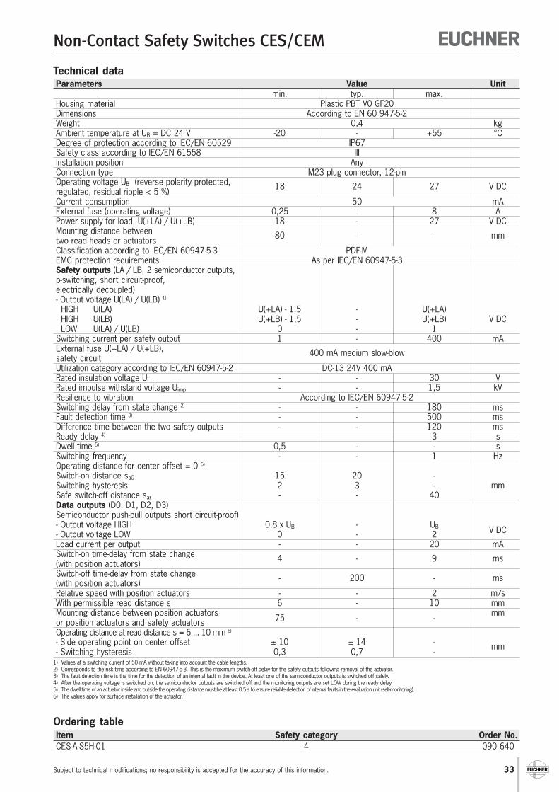
33
Non-Contact Safety Switches CES/CEM
Subject to technical modifications; no responsibility is accepted for the accuracy of this information.
Technical dataParameters Value Unit
min. typ. max.Housing material Plastic PBT V0 GF20Dimensions According to EN 60 947-5-2Weight 0,4 kgAmbient temperature at UB = DC 24 V -20 - +55 °CDegree of protection according to IEC/EN 60529 IP67Safety class according to IEC/EN 61558 IIIInstallation position AnyConnection type M23 plug connector, 12-pinOperating voltage UB (reverse polarity protected,regulated, residual ripple < 5 %)
18 24 27 V DC
Current consumption 50 mAExternal fuse (operating voltage) 0,25 - 8 APower supply for load U(+LA) / U(+LB) 18 - 27 V DCMounting distance betweentwo read heads or actuators 80 - - mm
Classification according to IEC/EN 60947-5-3 PDF-MEMC protection requirements As per IEC/EN 60947-5-3Safety outputs (LA / LB, 2 semiconductor outputs,p-switching, short circuit-proof,electrically decoupled)- Output voltage U(LA) / U(LB) 1)
HIGH U(LA) U(+LA) - 1,5 - U(+LA) HIGH U(LB) U(+LB) - 1,5 - U(+LB) V DC LOW U(LA) / U(LB) 0 - 1Switching current per safety output 1 - 400 mAExternal fuse U(+LA) / U(+LB),safety circuit 400 mA medium slow-blow
Utilization category according to IEC/EN 60947-5-2 DC-13 24V 400 mARated insulation voltage Ui - - 30 VRated impulse withstand voltage Uimp - - 1,5 kVResilience to vibration According to IEC/EN 60947-5-2Switching delay from state change 2) - - 180 msFault detection time 3) - - 500 msDifference time between the two safety outputs - - 120 msReady delay 4) 3 sDwell time 5) 0,5 - - sSwitching frequency - - 1 HzOperating distance for center offset = 0 6)
Switch-on distance sa0 15 20 -Switching hysteresis 2 3 - mmSafe switch-off distance sar - - 40Data outputs (D0, D1, D2, D3)Semiconductor push-pull outputs short circuit-proof)- Output voltage HIGH 0,8 x UB - UB V DC- Output voltage LOW 0 - 2Load current per output - - 20 mASwitch-on time-delay from state change(with position actuators) 4 - 9 ms
Switch-off time-delay from state change(with position actuators) - 200 - ms
Relative speed with position actuators - - 2 m/sWith permissible read distance s 6 - 10 mmMounting distance between position actuators
75 - -mm
or position actuators and safety actuatorsOperating distance at read distance s = 6 ... 10 mm 6)
- Side operating point on center offset ± 10 ± 14 -- Switching hysteresis 0,3 0,7 -
mm
1) Values at a switching current of 50 mA without taking into account the cable lengths.2) Corresponds to the risk time according to EN 60947-5-3. This is the maximum switch-off delay for the safety outputs following removal of the actuator.3) The fault detection time is the time for the detection of an internal fault in the device. At least one of the semiconductor outputs is switched off safely.4) After the operating voltage is switched on, the semiconductor outputs are switched off and the monitoring outputs are set LOW during the ready delay.5) The dwell time of an actuator inside and outside the operating distance must be at least 0.5 s to ensure reliable detection of internal faults in the evaluation unit (self-monitoring).6) The values apply for surface installation of the actuator.
Ordering tableItem Safety category Order No.CES-A-S5H-01 4 090 640
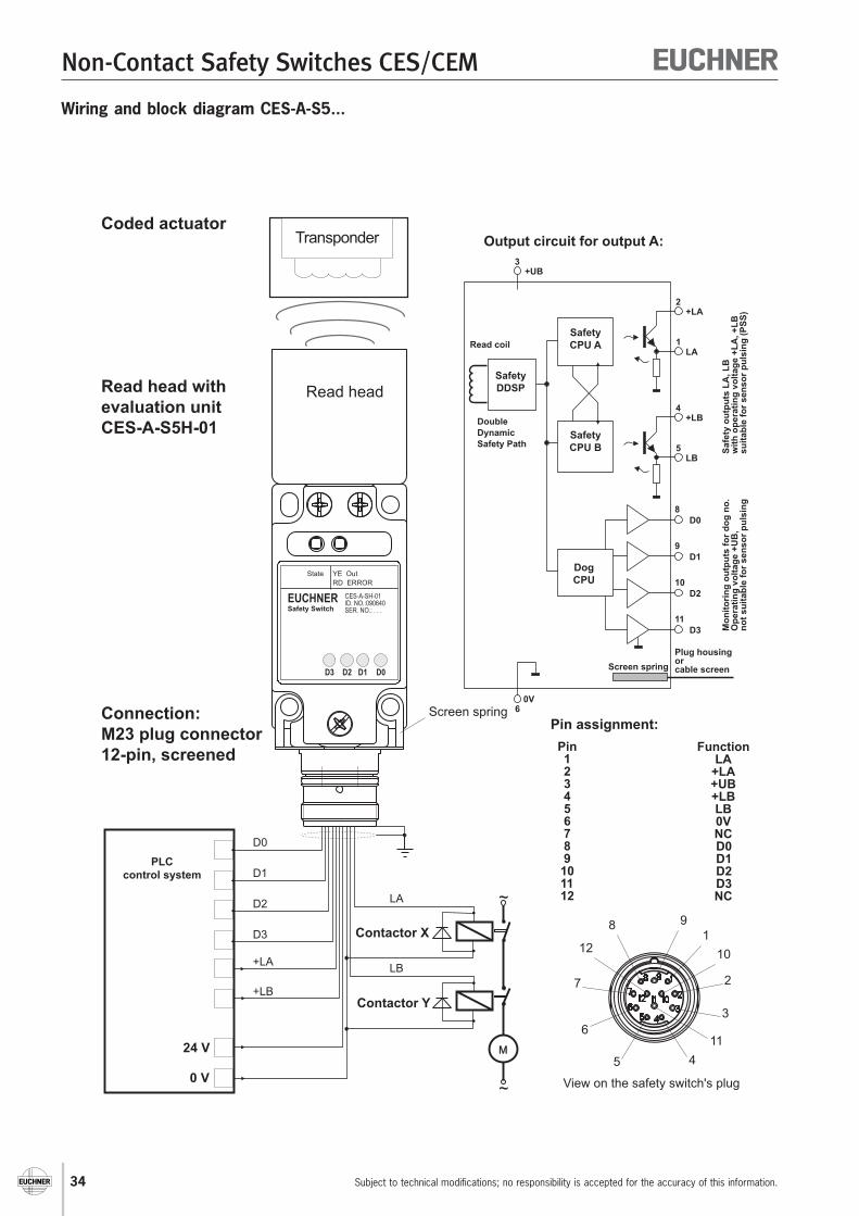
34
Non-Contact Safety Switches CES/CEM
Subject to technical modifications; no responsibility is accepted for the accuracy of this information.
M
~
~
M1
1
0 V
24 V
D0
D1
D2
D3
+LA
+LB
Coded actuatorTransponder
Read head with
evaluation unit
CES-A-S5H-01
Connection:
M23 plug connector
12-pin, screened
PLC
control system
Read head
Contactor X
Contactor Y
Output circuit for output A:
Pin assignment:
Pin123456789
101112
FunctionLA
+LA+UB+LBLB0VNCD0D1D2D3NC
View on the safety switch's plug
LA
+LA
LB
+LB
D0
D1
D2
D3
Safe
ty o
utp
uts
LA
, L
B
wit
h o
pera
tin
g v
olt
ag
e +
LA
, +
LB
su
itab
le f
or
sen
so
r p
uls
ing
(P
SS
)
Mo
nit
ori
ng
ou
tpu
ts f
or
do
g n
o.
Op
era
tin
g v
olt
ag
e +
UB
,n
ot
su
itab
le f
or
sen
so
r p
uls
ing
Safety
CPU A
Safety
CPU B
Dog
CPU
Safety
DDSP
Read coil
Double
Dynamic
Safety Path
0V
Screen spring
M
LA
LB
1
2
3
45
6
7
8 9
10
1
12
Screen spring
1
2
5
4
8
9
10
1
+UB3
6
Plug housingorcable screen
State YE Out
RD ERROR
EUCHNERSafety Switch
CES-A-SH-01
ID. NO.:090640
SER. NO.: . . .
D3 D2 D1 D0
Wiring and block diagram CES-A-S5...

35
Non-Contact Safety Switches CES/CEM
Subject to technical modifications; no responsibility is accepted for the accuracy of this information.
LEDs
Safety switch LED displaysLED labels LED color Significance
STATE Green Normal operationGreen flashing Teach-in operation
OUT/ERROR Yellow Safety actuator detectedRed Internal electronics error or invalid teach-in operation
Position sensor LED displaysLED labels LED color Significance
D0, D1, D2, D3 Yellow Indication of the actuator number (binary code)
Allocation table
Allocation of the actuator numbers to the safety outputs and data outputs
Actuator Safety outputs Data outputsLA LB D3 D2 D1 D0
Safety actuator 1 1 0 0 0 1Actuator 2 0 0 0 0 1 0Actuator 3 0 0 0 0 1 1Actuator 4 0 0 0 1 0 0Actuator 5 0 0 0 1 0 1Actuator 6 0 0 0 1 1 0Actuator 7 0 0 0 1 1 1Actuator 8 0 0 1 0 0 0Actuator 9 0 0 1 0 0 1Actuator A 0 0 1 0 1 0Actuator B 0 0 1 0 1 1Actuator C 0 0 1 1 0 0Actuator D 0 0 1 1 0 1Actuator E 0 0 1 1 1 0Actuator F 0 0 1 1 1 1
Pulse diagram Transponder
Nr.
in the
operating
distance
Yes
No
Safety outputs
LA, LBON
OFF
Position actuators
4 7 8 1
Safety actuator
Time t
200 ms
4 … 9 ms
200 ms
< 200 ms
30 … 180 ms
30 … 180 ms
Monitoring
outputs
D3
D2
D1
D0
ON
OFF
ON
OFF
ON
OFF
ON
OFF
t
t
t
t
t
If a new transponder enters the operating distance
within the switch-off delay,
the switch-off delay is interrupted and
the new transponder number signaled.

36
Non-Contact Safety Switches CES/CEM
Subject to technical modifications; no responsibility is accepted for the accuracy of this information.
Notes on installation The connection cable must only be extended
using EUCHNER plug connectors andadequate consideration must be given toEMC during assembly.Intermediate terminals must not be used.
Actuator and read head must be fitted sothat:The active faces (front faces) are at the
switch-on distance 0.8 x Sa0 or closer (seetechnical data) with the safety guard closed.
They are not used as a mechanical stop.They are positively mounted on the safety
guard, e.g. by using the safety screwsincluded.
Safety precautions If the read head and/or actuator is/are in-
stalled flush, the switching distance chan-ges as a function of the installation depthand the safety guard material.
2 safety screws M4x14included
Dimension drawing type CES-A-LNA...
Typical operating distance
Read head CES-A-LNA...
Cube-shaped design 42 x 25 mm Hard-wired cable In combination with evaluation units CES-A-A...
and actuators CES-A-BBA
With evaluation unit CES-A-ABA-01 and actuator CES-A-BBA With evaluation unit CES-A-ABA-01B/CES-A-AEA...and actuator CES-A-BBA
For a side approach direction for the actuator and read head, aminimum distance of s = 3 mm must be maintained so that theoperating distance of the side lobes is not entered.
Activeface
Activeface
CES-A-L XXXXXX25
∅8
∅4,
5
42
32 ±0,1
12
4,6
"l"
-8 -4-6 -2 2 64 80
2
4
6
8
Centre offset m [mm]
Dist
ance
s [m
m]
OFF
ON
Actuator
Read head
s
m
Hysteresis
Switch-ondistance Sa0
ON
OFF
Hysteresis
Distance sSa0
Output stage
Switch-offdistance
OFF
Secondarybeam
N
-10-15 -5 0Centre offset m [mm]
Dis
tanc
e s
[mm
]
OFF
ON
Switch-ondistance Sa0
ON
OFF
Hysteresis
Distance sSa0
Output state
Switch-offdistance
OFF
Hysteresis
-20 5 201510
5
10
15
20
Secondarybeam
N
Actuator
Read head
s
m

37
Non-Contact Safety Switches CES/CEM
Subject to technical modifications; no responsibility is accepted for the accuracy of this information.
Technical dataParameters Value Unit
min. typ. max.Housing material Fortron, reinforced thermoplastic, fully encapsulatedDimensions 42 x 25 x 12 mmWeight (incl. 10 m cable) 0.3 kgAmbient temperature -25 - +70 °CDegree of protection IP67Installation position AnyMethod of operation InductiveDynamic data transferto the evaluation unit 2 kbit/s
Power supply Via evaluation unitDwell time 1) 0.5 - - sOperating distance for center offset m = 0 2)
(evaluation unit CES-A-ABA-01 with CES-A-BBA)- Safe switch-off distance Sar - - 23Cable length l = 0 to 25 m- Switch-on distance Sa0 5 6 - mm- Switching hysteresis 0.5 1.5 -Cable length l ≥ 25 to 50 m- Switch-on distance Sa0 4 4.8 -- Switching hysteresis 0.4 1.2 -Operating distance for center offset m = 0 3)
(Evaluation unit CES-A-ABA-01B/CES-A-AEA...with CES-A-BBA)- Safe switch-off distance Sar - - 32Cable length l = 0 to 25 m- Switch-on distance Sa0 10 15 - mm- Switching hysteresis 0.5 2 -Cable length l ≥ 25 to 50 m- Switch-on distance Sa0 8 12 -- Switching hysteresis 0.4 1.6 -Connection cable Hard-wired encapsulated connection cable, with crimped ferrules
PVC, ∅ 4.6 mmPUR, ∅ 4.8 mm, suitable for drag chain
Cable length See ordering table 50 m1) The dwell time is the time that the actuator must be inside or outside the operating distance.2) These values apply for flush installation of the read head and the actuator in aluminum.3) These values apply for surface installation of the read head and the actuator.
Ordering tableCable type
Series Cable length „l“ (meters) V = PVC Item Order No.P = PUR
-05 V CES-A-LNA-05V 071 845-10 V CES-A-LNA-10V 071 846-15 V CES-A-LNA-15V 071 847
CES-A-LNA... -25 V CES-A-LNA-25V 071 975-50 V CES-A-LNA-50V 077 795-05 P CES-A-LNA-05P 077 806-10 P CES-A-LNA-10P 077 807-15 P CES-A-LNA-15P 084 682
Pin assignment
Read head with connection cable
H1a H1b SH1
BNWH
Screen
Evaluation unitCES-A-AEA...
Read head
H1 H2 SH
BNWH
Screen
Evaluation unitCES-A-ABA...
Read head

38
Non-Contact Safety Switches CES/CEM
Subject to technical modifications; no responsibility is accepted for the accuracy of this information.
Dimension drawing type CES-A-LNA-SC
2 safety screws M4x14included
Notes on installation The connection cable must only be extended
using EUCHNER plug connectors andadequate consideration must be given toEMC during assembly (see page 66).Intermediate terminals must not be used.
Actuator and read head must be fitted sothat:The active faces (front faces) are at the
switch-on distance 0.8 x Sa0 or closer (seetechnical data) with the safety guard closed.
They are not used as a mechanical stop.They are positively mounted on the safety
guard, e.g. by using the safety screwsincluded.
Safety precautions If the read head and/or actuator is/are
installed flush, the switching distancechanges as a function of the installationdepth and the safety guard material.
Typical operating distance
Read head CES-A-LNA-SC
Cube-shaped design 42 x 25 mm M8 plug connector (snap-action and screw terminals)
(M8 connection cable see page 64) In combination with evaluation units CES-A-A...
and actuators CES-A-BBA
With evaluation unit CES-A-ABA-01 and actuator CES-A-BBA With evaluation unit CES-A-ABA-01B/CES-A-AEA...and actuator CES-A-BBA
For a side approach direction for the actuator and read head, aminimum distance of s = 3 mm must be maintained so that theoperating distance of the side lobes is not entered.
Cable outlet withangledplug connector
Activeface
Activeface
5,5
∅10
6,8
∅8
∅4,
5
4,6
12
25
min.38
32 ±0,1
4232,6
A0
CES-A-L 077715
3
4
1
A0
CES-A-L 077715
20 1,
26,5
-8 -4-6 -2 2 64 80
2
4
6
8
Centre offset m [mm]
Dist
ance
s [m
m]
OFF
ON
Actuator
Read head
s
m
Hysteresis
Switch-ondistance Sa0
ON
OFF
Hysteresis
Distance sSa0
Output stage
Switch-offdistance
OFF
Secondarybeam
N
-10-15 -5 0Centre offset m [mm]
Dis
tanc
e s
[mm
]
OFF
ON
Switch-ondistance Sa0
ON
OFF
Hysteresis
Distance sSa0
Output state
Switch-offdistance
OFF
Hysteresis
-20 5 201510
5
10
15
20
Secondarybeam
N
Actuator
Read head
s
m

39
Non-Contact Safety Switches CES/CEM
Subject to technical modifications; no responsibility is accepted for the accuracy of this information.
Ordering tableItem Order No.
CES-A-LNA-SC 077 715
Technical dataParameters Value Unit
min. typ. max.Housing material Fortron, reinforced thermoplastic, fully encapsulatedDimensions 42 x 25 x 12 mmWeight (incl. 10 m cable) 0.3 kgAmbient temperature -25 - +70 °CDegree of protection IP67Installation position AnyMethod of operation InductiveDynamic data transferto the evaluation unit 2 kbit/s
Power supply Via evaluation unitDwell time 1) 0.5 - - sOperating distance for center offset m = 0 2)
(Evaluation unit CES-A-ABA-01 with CES-A-BBA)- Safe switch-off distance Sar - - 23Cable length l = 0 to 25 m- Switch-on distance Sa0 5 6 - mm- Switching hysteresis 0.5 1.5 -Cable length l ≥ 25 to 50 m- Switch-on distance Sa0 4 4.8 -- Switching hysteresis 0.4 1.2 -Operating distance for center offset m = 0 3)
(Evaluation unit CES-A-ABA-01B/CES-A-AEA-04Bwith CES-A-BBA)- Safe switch-off distance Sar - - 32Cable length l = 0 to 25 m- Switch-on distance Sa0 10 15 - mm- Switching hysteresis 0.5 2 -Cable length l ≥ 25 to 50 m- Switch-on distance Sa0 8 12 -- Switching hysteresis 0.4 1.6 -Connection M8 plug connector (snap-action and screw terminals), 3-pinConnection cable - - 50 m
1) The dwell time is the time that the actuator must be inside or outside the operating distance.2) These values apply for flush installation of the read head and the actuator in aluminum.3) These values apply for surface installation of the read head and the actuator.
Pin assignmentRead head with plug connector
H1a H1b SH1
1
34
BNWH
Evaluation unitCES-A-AEA...
Viewon plug connectorfor the read head
Screen
H1 H2 SH
1
34
BNWH
Evaluation unitCES-A-ABA...
Viewon plug connectorfor the read head
Screen
40
Non-Contact Safety Switches CES/CEM
Subject to technical modifications; no responsibility is accepted for the accuracy of this information.
Notes on installation The flat seal provided must be used during
assembly. The connection cable must only be extended
using EUCHNER plug connectors andadequate consideration must be given toEMC during assembly (see page 66).Intermediate terminals must not be used.
Actuator and read head must be fitted sothat:The active faces (front faces) are at the
switch-on distance 0.8 x Sa0 or closer (seetechnical data) with the safety guard closed.
They are not used as a mechanical stop.They are positively mounted on the safety
guard, e.g. by using the safety screwsincluded.
Safety precautions If the read head and/or actuator is/are
installed flush, the switching distancechanges as a function of the installationdepth and the safety guard material.
2 safety screws M4x14included
Dimension drawing type CES-A-LCA...
Read head CES-A-LCA...
Cube-shaped design 42 x 25 mm Plastic PE-HD housing material, suitable for use in aggressive
media (e.g. acids, alkaline) In combination with evaluation units CES-A-A...
and actuators CES-A-BCA
Flat seal included
Typical operating distance
With evaluation unit CES-A-ABA-01 and actuator CES-A-BBA With evaluation unit CES-A-ABA-01B/CES-A-AEA...and actuator CES-A-BBA
For a side approach direction for the actuator and read head, aminimum distance of s = 3 mm must be maintained so that theoperating distance of the side lobes is not entered.
Activeface
Activeface
Flatseal
32
42
48
25 31
l
12
14
4,6
∅8∅
4,5
± 0,1
-8 -4-6 -2 2 64 80
2
4
6
8
Centre offset m [mm]
Dist
ance
s [m
m]
OFF
ON
Actuator
Read head
s
m
Hysteresis
Switch-ondistance Sa0
ON
OFF
Hysteresis
Distance sSa0
Output stage
Switch-offdistance
OFF
Secondarybeam
N
-10-15 -5 0Centre offset m [mm]
Dis
tanc
e s
[mm
]
OFF
ON
Switch-ondistance Sa0
ON
OFF
Hysteresis
Distance sSa0
Output state
Switch-offdistance
OFF
Hysteresis
-20 5 201510
5
10
15
20
Secondarybeam
N
Actuator
Read head
s
m
41
Non-Contact Safety Switches CES/CEM
Subject to technical modifications; no responsibility is accepted for the accuracy of this information.
Pin assignment
Read head with connection cable
H1a H1b SH1
BNWH
Screen
Evaluation unitCES-A-AEA...
Read head
H1 H2 SH
BNWH
Screen
Evaluation unitCES-A-ABA...
Read head
Technical dataParameters Value Unit
min. typ. max.Housing material Plastic PE-HD without reinforcing, fully encapsulatedFlat seal material Fluororubber 75 FPM 4100Dimensions 42 x 25 x 12 mmWeight (incl. 10 m cable) 0.3 kgAmbient temperature -25 - +50 °CDegree of protection IP67Installation position AnyMethod of operation InductiveDynamic data transferto the evaluation unit 2 kbit/s
Power supply Via evaluation unitDwell time 1) 0.5 - - sOperating distance for center offset m = 0 2)
(Evaluation unit CES-A-ABA-01 with CES-A-BBA)- Safe switch-off distance Sar - - 23Cable length l = 0 to 25 m- Switch-on distance Sa0 5 6 - mm- Switching hysteresis 0.5 1.5 -Cable length l ≥ 25 to 50 m- Switch-on distance Sa0 4 4.8 -- Switching hysteresis 0.4 1.2 -Operating distance for center offset m = 0 3)
(Evaluation unit CES-A-ABA-01B/CES-A-AEA...with CES-A-BBA)- Safe switch-off distance Sar - - 32Cable length l = 0 to 25 m- Switch-on distance Sa0 10 15 - mm- Switching hysteresis 0.5 2 -Cable length l ≥ 25 to 50 m- Switch-on distance Sa0 8 12 -- Switching hysteresis 0.4 1.6 -Connection cable Hard-wired encapsulated connection cable, with crimped ferrules
PVC, ∅ 4.6 mmCable length See ordering table 50 m
1) The dwell time is the time that the actuator must be inside or outside the operating distance.2) These values apply for flush installation of the read head and the actuator in aluminum.3) These values apply for surface installation of the read head and the actuator.
Ordering tableCable type
Series Cable length „l“ (meters) V = PVC Item Order No.P = PUR
CES-A-LCA... -10 V CES-A-LCA-10V 088 785

42
Non-Contact Safety Switches CES/CEM
Subject to technical modifications; no responsibility is accepted for the accuracy of this information.
Notes on installation The connection cable must only be extended
using EUCHNER plug connectors andadequate consideration must be given toEMC during assembly (see page 66).Intermediate terminals must not be used.
Actuator and read head must be fitted sothat:The active faces (front faces) are at the
switch-on distance 0.8 x Sa0 or closer (seetechnical data) with the safety guard closed.
They are not used as a mechanical stop.They are positively connected to the safety
guard, e.g. by using adhesive. The read head is allowed to be installed as
a maximum up to the clear zone (area ofthe active face without metal housing).
Safety precautions If the read head is installed flush, the
switching distance changes as a functionof the installation depth and the safety guardmaterial.
Dimension drawing type CES-A-LMN-SC
1)Clear zone (area of the active face without metal housing)
Read head series CES-A-LMN-SC
Cylindrical design M12 M8 plug connector (snap-action and screw terminals)
(M8 connection cable see page 64) In combination with evaluation units CES-A-A...
and actuators CES-A-BMB
Typical operating distance
Activeface
With evaluation unit CES-A-ABA-01 and actuator CES-A-BMB With evaluation unit CES-A-ABA-01B/CES-A-AEA...and actuator CES-A-BMB
A minimum distance of s = 1.2 mm must be maintained.
17
5
32 19,7
Reading distance s
Cen
tre
offs
et
m
connected
354
830
M12
x1
M8x
1
37
1)
1)
-4 -2-3 -1 1 32 40
1
2
3
4
Centre offset m [mm]
Dis
tanc
e s
[mm
]
OFF
ON
Actuator
Readhead
s
m
Hysteresis
Switch-ondistance Sa0
ON
OFF
Hysteresis
Distance sSa0
Output state
Switch-offdistance OFF
-4-6 -2 0Centre offset m [mm]
Dis
tanc
e s
[mm
]
OFF
ON
Switch-ondistance Sa0
ON
OFF
Hysteresis
Distance sSa0
Output state
Switch-offdistance OFF
-8 2 864
2
4
6
8
Actuator
Readhead
s
m
not permissible area not permissible area
Hysteresis
43
Non-Contact Safety Switches CES/CEM
Subject to technical modifications; no responsibility is accepted for the accuracy of this information.
Technical dataParameters Value Unit
min. typ. max.Housing material Nickel-plated CuZn housing sleeve
Plastic PBT GF20 capDimensions M12 x 1, length 38 mmWeight (incl. 10 m cable) 0.2 kgAmbient temperature -25 - +70 °CDegree of protection IP67Installation position AnyMethod of operation InductiveDynamic data transfer 2to the evaluation unit kbpsPower supply Via evaluation unitDwell time 1) 0.5 - - sOperating distance for center offset m = 0 2)
(Evaluation unit CES-A-ABA-01 with CES-A-BMB)- Safe switch-off distance Sar - - 8.5Cable length l = 0 to 10 m- Switch-on distance Sa0 1.6 2.5 - mm- Switching hysteresis 0.2 0.3 -Operating distance for center offset m = 0 2)
(Evaluation unit CES-A-ABA-01B/CES-A-AEA-04Bwith CES-A-BMB)- Safe switch-off distance Sar - - 10Cable length l = 0 to 10 m- Switch-on distance Sa0 3.5 5 - mm- Switching hysteresis 0.1 0.3 -Connection M8 plug connector (snap-action and screw terminals), 3-pinConnection cable - - 15 m
1) The dwell time is the time that the actuator must be inside or outside the operating distance.2) These values apply for surface installation of the read head in steel.
Ordering tableItem Order No.
CES-A-LMN-SC 077 790
Pin assignmentRead head with plug connector
H1a H1b SH1
1
34
BNWH
Evaluation unitCES-A-AEA...
Viewon plug connectorfor the read head
Screen
H1 H2 SH
1
34
BNWH
Evaluation unitCES-A-ABA...
Viewon plug connectorfor the read head
Screen

44
Non-Contact Safety Switches CES/CEM
Subject to technical modifications; no responsibility is accepted for the accuracy of this information.
2 safety screws M4x14included
Dimension drawing CES-A-BCA
Ordering tableItem Order No.
CES-A-BBA 071 840CES-A-BCA (flat seal included) 088 786
Notes on installation Actuator and read head must be fitted so
that:The active faces (front faces) are at the
switch-on distance 0.8 x Sa0 or closer (seetechnical data) with the safety guard closed.
They are not used as a mechanical stop.They are positively mounted on the safety
guard, e.g. by using the safety screwsincluded.
CES-A-BCA: The flat seal provided must beused during assembly.
2 safety screws M4x14included
Dimension drawing CES-A-BBA
Actuator CES-A-BBA / CES-A-BCA
Cube-shaped design 42 x 25 mm CES-A-BCA suitable for use in aggressive media
(e.g. acids, alkaline) In combination with evaluation units CES-A-A...,
read head CES-A-LNA... and safety switches CES-A-C5...
Technical dataParameters Value Unit
min. typ. max.Housing material CES-A-BBA Fortron, reinforced thermoplastic, fully encapsulated
CES-A-BCA Plastic PE-HD without reinforcing, fully encapsulatedFlat seal material CES-A-BCA Fluororubber 75 FPM 4100Dimensions 42 x 25 x 12 mmWeight 0.02 kgAmbient temperature CES-A-BBA -25 - +70 °C
CES-A-BCA -25 - +50 °CDegree of protection IP67Installation position Active face opposite read headPower supply Inductive via read headDwell time 1) 0.5 - - s
1) The dwell time is the time that the actuator must be inside or outside the operating distance.
CES-A-B 071840
25
ø8ø4,5
42
32 ±0,1
12
4,6
42
32± 0,10
25 31
48
∅4,
5
∅8
2 12
4,6
Activeface
Activeface
Activeface
Activeface
Flatseal
Flatseal
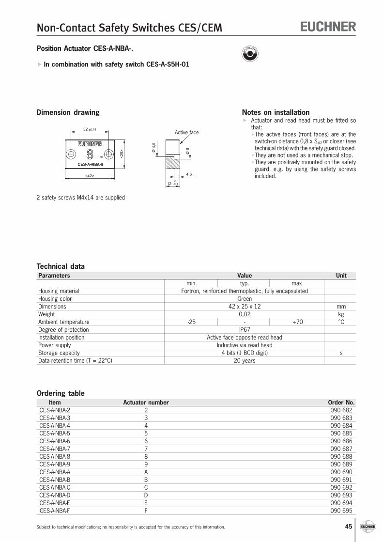
45
Non-Contact Safety Switches CES/CEM
Subject to technical modifications; no responsibility is accepted for the accuracy of this information.
AB
0,1
32 ±0,15
<42>
<2
5>
Ø8
Ø4
,5
4,6
12 -0
Ordering tableItem Actuator number Order No.
CES-A-NBA-2 2 090 682CES-A-NBA-3 3 090 683CES-A-NBA-4 4 090 684CES-A-NBA-5 5 090 685CES-A-NBA-6 6 090 686CES-A-NBA-7 7 090 687CES-A-NBA-8 8 090 688CES-A-NBA-9 9 090 689CES-A-NBA-A A 090 690CES-A-NBA-B B 090 691CES-A-NBA-C C 090 692CES-A-NBA-D D 090 693CES-A-NBA-E E 090 694CES-A-NBA-F F 090 695
Notes on installation Actuator and read head must be fitted so
that:The active faces (front faces) are at the
switch-on distance 0,8 x Sa0 or closer (seetechnical data) with the safety guard closed.
They are not used as a mechanical stop.They are positively mounted on the safety
guard, e.g. by using the safety screwsincluded.
2 safety screws M4x14 are supplied
Active face
Dimension drawing
Position Actuator CES-A-NBA-.
In combination with safety switch CES-A-S5H-01
Technical dataParameters Value Unit
min. typ. max.Housing material Fortron, reinforced thermoplastic, fully encapsulatedHousing color GreenDimensions 42 x 25 x 12 mmWeight 0,02 kgAmbient temperature -25 - +70 °CDegree of protection IP67Installation position Active face opposite read headPower supply Inductive via read headStorage capacity 4 bits (1 BCD digit) sData retention time (T = 22°C) 20 years
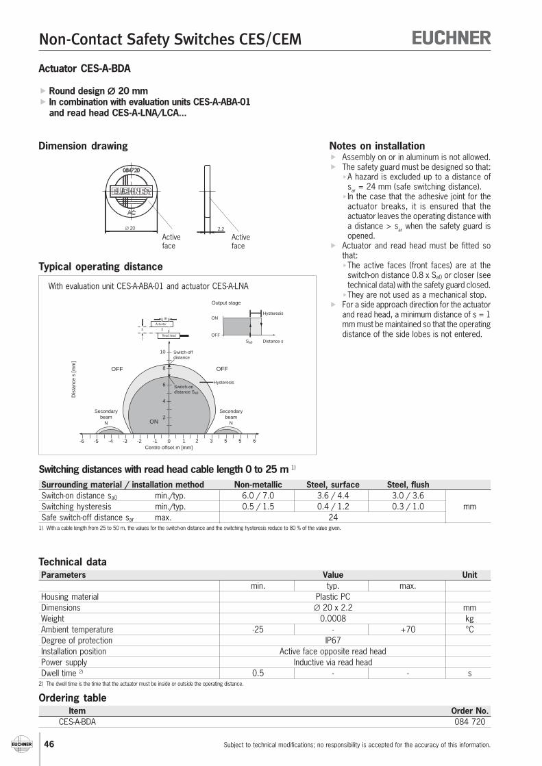
46
Non-Contact Safety Switches CES/CEM
Subject to technical modifications; no responsibility is accepted for the accuracy of this information.
Technical dataParameters Value Unit
min. typ. max.Housing material Plastic PCDimensions ∅ 20 x 2.2 mmWeight 0.0008 kgAmbient temperature -25 - +70 °CDegree of protection IP67Installation position Active face opposite read headPower supply Inductive via read headDwell time 2) 0.5 - - s
2) The dwell time is the time that the actuator must be inside or outside the operating distance.
Ordering tableItem Order No.
CES-A-BDA 084 720
Notes on installation Assembly on or in aluminum is not allowed. The safety guard must be designed so that:
A hazard is excluded up to a distance ofsar = 24 mm (safe switching distance).
In the case that the adhesive joint for theactuator breaks, it is ensured that theactuator leaves the operating distance witha distance > sar when the safety guard isopened.
Actuator and read head must be fitted sothat:The active faces (front faces) are at the
switch-on distance 0.8 x Sa0 or closer (seetechnical data) with the safety guard closed.
They are not used as a mechanical stop. For a side approach direction for the actuator
and read head, a minimum distance of s = 1mm must be maintained so that the operatingdistance of the side lobes is not entered.
Dimension drawing
Actuator CES-A-BDA
Round design ∅∅∅∅∅ 20 mm In combination with evaluation units CES-A-ABA-01
and read head CES-A-LNA/LCA...
Typical operating distance
Surrounding material / installation method Non-metallic Steel, surface Steel, flushSwitch-on distance sa0 min./typ. 6.0 / 7.0 3.6 / 4.4 3.0 / 3.6Switching hysteresis min./typ. 0.5 / 1.5 0.4 / 1.2 0.3 / 1.0 mmSafe switch-off distance sar max. 24
1) With a cable length from 25 to 50 m, the values for the switch-on distance and the switching hysteresis reduce to 80 % of the value given.
Switching distances with read head cable length 0 to 25 m 1)
With evaluation unit CES-A-ABA-01 and actuator CES-A-LNA
∅ 20 2,2
Activeface
Activeface
Secondarybeam
N
-6 -2-3 -1 0Centre offset m [mm]
Dis
tanc
e s
[mm
]
OFF
ON
HysteresisSwitch-ondistance Sa0
ON
OFF
Hysteresis
Distance sSa0
Output stage
Switch-offdistance
OFF
-4-5 1 55 632
2
4
8
Secondarybeam
N
Actuator
Read head
s
m
6
10

47
Non-Contact Safety Switches CES/CEM
Subject to technical modifications; no responsibility is accepted for the accuracy of this information.
11
0,80
6
M12
x0,7
5
Notes on installation Actuator and read head must be fitted so
that:The active faces (front faces) are at the
switch-on distance 0.8 x Sa0 or closer (seetechnical data) with the safety guard closed.
They are not used as a mechanical stop.They are positively connected to the safety
guard, e.g. by using adhesive. The actuator can be screwed into the
M12 x 0.75 thread provided with the aid ofan insertion tool (Order No. 037 662).
Flush installation of the actuator in steel isallowed.
Technical dataParameters Value Unit
min. typ. max.Housing material Stainless steel, NiroDimensions M12 x 0.75, depth 6 mmWeight 0.002 kgAmbient temperature -25 - +70 °CDegree of protection IP67Installation position Active face opposite read headPower supply Inductive via read headDwell time 1) 0.5 - - s
1) The dwell time is the time that the actuator must be inside or outside the operating distance.
Ordering tableItem Order No.
CES-A-BMB 077 791
Dimension drawing
Actuator CES-A-BMB
Cylindrical design M12 x 0.75 In combination with evaluation units CES-A-A...,
read head CES-A-LMN-SC and read head CES-A-LNA.../LCA...(operating distance on request)
Active face

48
Non-Contact Safety Switches CES/CEM
Subject to technical modifications; no responsibility is accepted for the accuracy of this information.
Non-contact safety switches CEM
With transponder coding Integrated solenoid (without monitoring of the guard locking) Up to safety category 4
Functional descriptionNon-contact safety switches CES have no guard locking. Therefore,there is a risk that the machining process may be interrupted ifthe safety door is opened unintentionally.The safety switch CEM is the ideal solution for all customers whomust achieve a high level of safety when securing a safety guardand also need guard locking to protect the process.The guard locking on the safety switch CEM is not monitored bythe system as per EN 1088. As a consequence, the switch canbe used in all applications in which there are no hazardous,overtravel machine movements.If the overtravel machine movements do not represent a hazardfor the operator, the safety switch CEM can be used.
Design and functionalityThe safety switch CEM comprises a CEM actuator and read head.A CES read head and a solenoid are integrated into the CEM readhead. The CEM read head is connected to the CES evaluation unitwith a round M8 plug connector. The CEM actuator of identicaldesign also has a metal plate in addition to the transponder; thisplate acts as an armature for the solenoid coil.When the safety door is closed, the CEM actuator enters theoperating distance of the CEM read head. The transponder signalsare transferred, and then the evaluation unit closes the safetycontacts and sets the OUT output "high". By applying voltage tothe solenoid for the CEM read head, strong magnetic forces canbe generated between the coil (in the read head) and the armature(in the actuator).Depending on the switch design – EUCHNER provides two diffe-rent housing sizes – adhesive forces of approx. 500 N or 1000 Nrespectively are applied between the CEM actuator and the CEMread head. Practical experience has shown that these magneticadhesive forces effectively prevent any opening, even if the userapplies an enormous amount of effort.
Use of the switch even in extremely harsh environmentsThe safety switches CEM have an extremely robust design. Thehigh degree of protection IP 67 and the metal housing allow theswitch to be used in extremely harsh environments. The armatureplate for the CEM actuator has spring bearings and can be tiltedup to an angle of ± 4°. Therefore, when a maladjusted safetydoor is closed, the CEM actuator adjusts itself independently tothe surface of the CEM read head. It is not necessary to readjustthe safety door when using the safety switch CEM. When mountingthe safety switch CEM, it is only necessary to ensure that theCEM actuator is guided in front of the CEM read head when thedoor is closed, so that the strong adhesive forces can begenerated.Because the switch has only a small number of moving partswhich can wear, the mechanical life of the CEM switch is virtuallyunlimited.
Different designsEUCHNER provides two CEM housing designs. The two versionsdiffer in their dimensions, according to the size of the solenoid.The safety switches CEM with an adhesive force of 1000 N areused with large, heavy safety doors. This read head has an addi-tional M8 plug connector for connecting an external LED display.When voltage is applied to the coil, it is indicated to the user thatthe safety door is in the locking position. An LED display in theimmediate vicinity of the door handle is extremely advantageous,especially in the case of large, solid doors.The smaller version of the safety switch CEM has an adhesiveforce of approx. 500 N. It is suitable for securing smaller safetydoors and safety flaps.An LED indicator in the M8 plug on the CEM A LE05K S2 readhead indicates to the user when voltage is applied to the solenoid.
Highest possible level of safety is achievedEUCHNER offers various evaluation units for the safety switchCEM:
For the connection of one read head, the evaluation unitCES-A-ABA-01B (safety category 3)
For the connection of one/two read heads, the evaluation unitCES-A-ABA-02B (safety category 4)
For the connection of up to four read heads, the evaluationunit CES-A-ABA-04B (safety category 4).
In combined operation, it is possible to connect both CES readheads (without guard locking) and CEM read heads to an evaluationunit.In the case of relatively large systems with several safety doorsto be monitored, it is advisable to lock the frequently used doorsduring the production cycle – e.g. the doors in a cycling loadingstation – to prevent the process being interrupted if the door isopened. On doors that are not opened very often – e.g.maintenance doors – a safety switch without guard locking isadequate in many applications.
As the safety switch CEM only safely monitors the position of thedoor and not the function of the guard locking, the switch can beused in all systems without dangerous, overtravel machinemovements. The solenoid has the task of protecting the process;it effectively prevents the unintentional opening of the safety guardby the user.
With the two safety switches CES and CEM, EUCHNER haslaunched on the market a totally new safety concept that issignificantly different to competitive solutions.
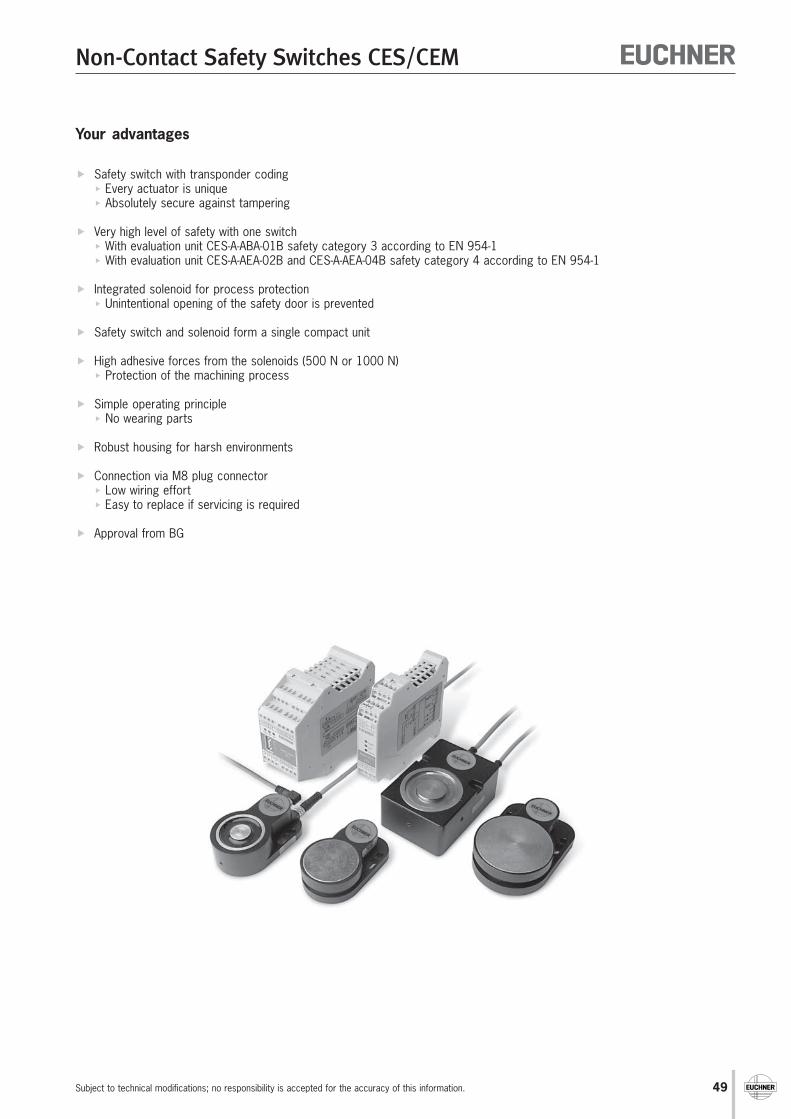
49
Non-Contact Safety Switches CES/CEM
Subject to technical modifications; no responsibility is accepted for the accuracy of this information.
Your advantages
Safety switch with transponder coding Every actuator is unique Absolutely secure against tampering
Very high level of safety with one switch With evaluation unit CES-A-ABA-01B safety category 3 according to EN 954-1 With evaluation unit CES-A-AEA-02B and CES-A-AEA-04B safety category 4 according to EN 954-1
Integrated solenoid for process protection Unintentional opening of the safety door is prevented
Safety switch and solenoid form a single compact unit
High adhesive forces from the solenoids (500 N or 1000 N) Protection of the machining process
Simple operating principle No wearing parts
Robust housing for harsh environments
Connection via M8 plug connector Low wiring effort Easy to replace if servicing is required
Approval from BG
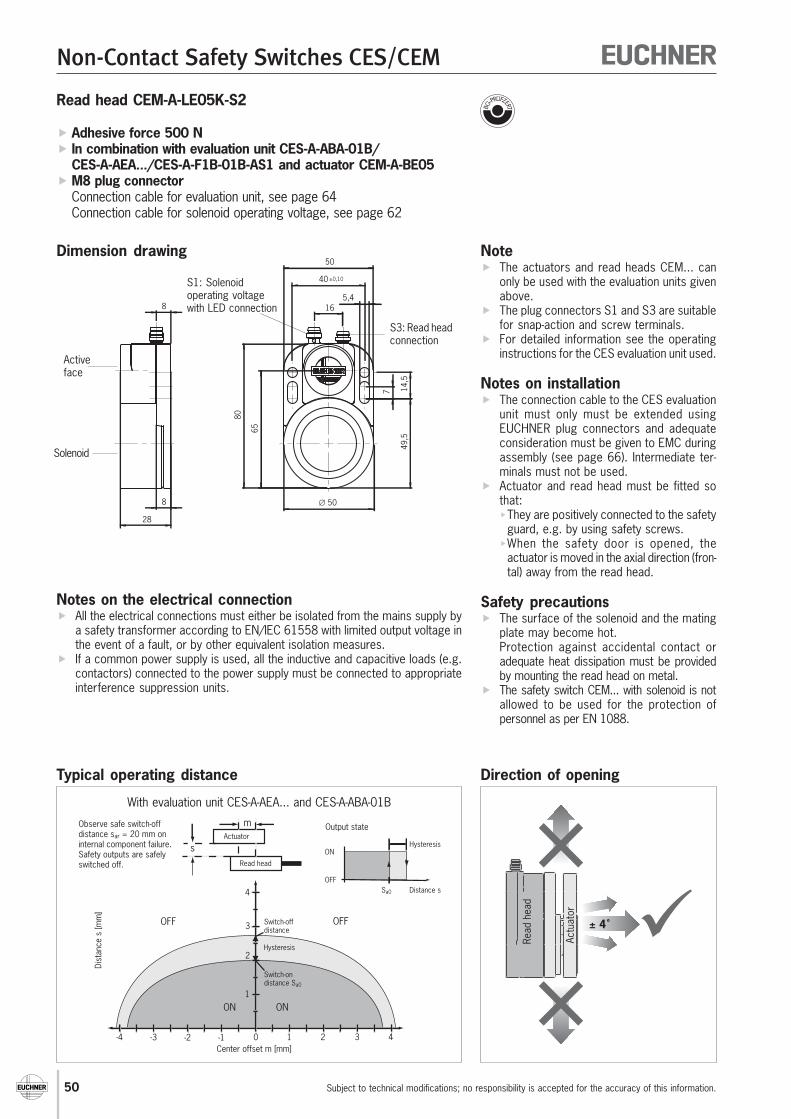
50
Non-Contact Safety Switches CES/CEM
Subject to technical modifications; no responsibility is accepted for the accuracy of this information.
Note The actuators and read heads CEM... can
only be used with the evaluation units givenabove.
The plug connectors S1 and S3 are suitablefor snap-action and screw terminals.
For detailed information see the operatinginstructions for the CES evaluation unit used.
Notes on installation The connection cable to the CES evaluation
unit must only must be extended usingEUCHNER plug connectors and adequateconsideration must be given to EMC duringassembly (see page 66). Intermediate ter-minals must not be used.
Actuator and read head must be fitted sothat:They are positively connected to the safety
guard, e.g. by using safety screws.When the safety door is opened, the
actuator is moved in the axial direction (fron-tal) away from the read head.
Safety precautions The surface of the solenoid and the mating
plate may become hot.Protection against accidental contact oradequate heat dissipation must be providedby mounting the read head on metal.
The safety switch CEM... with solenoid is notallowed to be used for the protection ofpersonnel as per EN 1088.
Dimension drawing
Typical operating distance
-4 -2-3 -1 1 32 40
1
2
3
4
Center offset m [mm]
Dist
ance
s [m
m]
OFF
ON
Hysteresis
Switch-ondistance Sa0
ON
OFF
Hysteresis
Distance sSa0
Output state
Switch-offdistance
OFF
Actuator
Read head
s
m
ON
Observe safe switch-offdistance sar = 20 mm oninternal component failure. Safety outputs are safelyswitched off.
Read head CEM-A-LE05K-S2
Adhesive force 500 N In combination with evaluation unit CES-A-ABA-01B/
CES-A-AEA.../CES-A-F1B-01B-AS1 and actuator CEM-A-BE05 M8 plug connector
Connection cable for evaluation unit, see page 64Connection cable for solenoid operating voltage, see page 62
S3: Read headconnection
16
∅ 50
40 ±0,10
5,4
49,5
7 14,5
80
6550
8
8
28
Activeface
S1: Solenoidoperating voltagewith LED connection
Direction of opening
Solenoid
With evaluation unit CES-A-AEA... and CES-A-ABA-01B
Read
hea
d
Actu
ator
± 4˚
Notes on the electrical connection All the electrical connections must either be isolated from the mains supply by
a safety transformer according to EN/IEC 61558 with limited output voltage inthe event of a fault, or by other equivalent isolation measures.
If a common power supply is used, all the inductive and capacitive loads (e.g.contactors) connected to the power supply must be connected to appropriateinterference suppression units.

51
Non-Contact Safety Switches CES/CEM
Subject to technical modifications; no responsibility is accepted for the accuracy of this information.
Ordering tableItem Adhesive force [N] Order No.CEM-A-LE05K-S2 500 094 800
Technical dataParameters Value UnitGeneral min. typ. max.Housing material AluminumMaterial, read head CES Plastic (PPS)Solenoid material Galvanized steelWeight Approx. 0.3 kgAmbient temperature -25 - +50 °CDegree of protection according to IEC 60529 IP67Installation position AnySolenoidAdhesive force in axial direction 500 NAdhesive force due to remanence 1) Approx. 15 NSolenoid center offset max. ± 2.5 mmSolenoid operating voltage UB plug S1 24 +10%/-15% V DCReverse polarity protection YesCurrent consumption 100 mAPower consumption Approx. 2.5 WSolenoid operating voltage connection M8 plug connector (plug), 4-pin
Yellow LED integrated in the plug connector (see circuit diagram)Read headOperating distance for center offset m = 0- Safe switch-off distance Sar - - 20
Cable length l = 0 to 25 m- Switch-on distance Sa0 - 2 - mm- Switching hysteresis - 0.7 -
Cable length l = 25 to 50 m- Switch-on distance Sa0 - 1.6 -- Switching hysteresis - 0.6 -Connection evaluation unit plug S3 M8 plug connector (plug), 3-pinConnection cable - - 50 m
1) The residual remanence disappears immediately when the door is opened and over time in solenoids through which there is no current flow.
Pin assignment
21
43
S1 S3
14
3
Solenoid operatingvoltage
S1.1 +UB/ DC 24VS1.2 -S1.3 0 V/GNDS1.4
Evaluationunit CES
S3.1 H1S3.3 H2S3.4 SH (screen)
S1/M8 plug S3/M8 plug
YE
0 V
+UB
NC
S1.4
S1.2
S1.1
S1.3
Circuit diagram connection ofsolenoid operating voltage S1
Sole
noid

52
Non-Contact Safety Switches CES/CEM
Subject to technical modifications; no responsibility is accepted for the accuracy of this information.
Note The actuators and read heads CEM... can
only be used with the evaluation units givenabove.
The plug connectors S1 and S3 are suitablefor snap-action and screw terminals.
For detailed information see the operatinginstructions for the CES evaluation unit used.
Notes on installation The connection cable to the CES evaluation
unit must only be extended using EUCHNERplug connectors and adequate considerati-on must be given to EMC during assembly.Intermediate terminals must not be used.
Actuator and read head must be fitted sothat:They are positively connected to the safety
guard, e.g. by using safety screws.When the safety door is opened, the
actuator is moved in the axial direction (fron-tal) away from the read head.
Safety precautions The surface of the solenoid and the mating
plate may become hot.Protection against accidental contact oradequate heat dissipation must be providedby mounting the read head on metal.
The safety switch CEM... with solenoid is notallowed to be used for the protection ofpersonnel as per EN 1088.
Dimension drawing
Typical operating distance
Adhesive force 500 N Without remanence In combination with evaluation unit CES-A-ABA-01B/
CES-A-AEA.../CES-A-F1B-01B-AS1 and actuator CEM-A-BE05 M8 plug connector
Direction of opening
Notes on the electrical connection All the electrical connections must either be isolated from the mains supply by
a safety transformer according to EN/IEC 61558 with limited output voltage inthe event of a fault, or by other equivalent isolation measures.
If a common power supply is used, all the inductive and capacitive loads (e.g.contactors) connected to the power supply must be connected to appropriateinterference suppression units.
Read head CEM-A-LE05R-S2
Read
hea
d
Actu
ator
± 4˚
-4 -2-3 -1 1 32 40
1
2
3
4
Center offset m [mm]
Dist
ance
s [m
m]
OFF
ON
Hysteresis
Switch-ondistance Sa0
ON
OFF
Hysteresis
Distance sSa0
Output state
Switch-offdistance
OFF
Actuator
Read head
s
m
ON
Observe safe switch-offdistance sar = 20 mm oninternal component failure. Safety outputs are safelyswitched off.
With evaluation unit CES-A-AEA... and CES-A-ABA-01B
S3: Read headconnection
16
∅ 50
40 ±0,10
5,4
49,5
7 14,5
80
6550
8
8
28
Activeface
S1: Solenoidoperating voltagewith LED connection
Solenoid

53
Non-Contact Safety Switches CES/CEM
Subject to technical modifications; no responsibility is accepted for the accuracy of this information.
Ordering tableItem Adhesive force [N] Order No.CEM-A-LE05R-S2 500 095 792
Technical dataParameters Value UnitGeneral min. typ. max.Housing material AluminumMaterial, read head CES Plastic (PPS)Solenoid material Galvanized steelWeight Approx. 0.3 kgAmbient temperature -25 - +50 °CDegree of protection according to IEC 60529 IP67Installation position AnySolenoidAdhesive force in axial direction 500 NAdhesive force due to remanence Approx. 0.5 NSolenoid center offset max. ± 2,5 mmSolenoid operating voltage UB plug S1 20.4 24 26.4 V DCReverse polarity protection YesCurrent consumption at connection S1.2 (UB) 100 mA
at connection S1.1 (MON) 15Power consumption Approx. 2.8 WSwitch-off delay 500 msSolenoid operating voltage connection M8 plug connector (plug), 4-pin
Yellow LED integrated in the plug connector (see circuit diagram)Read headOperating distance for center offset m = 0- Safe switch-off distance Sar - - 20
Cable length l = 0 to 25 m- Switch-on distance Sa0 - 2 - mm- Switching hysteresis - 0.7 -
Cable length l = 25 to 50 m- Switch-on distance Sa0 - 1.6 -- Switching hysteresis - 0.6 -Connection evaluation unit plug S3 M8 plug connector (plug), 3-pinConnection cable - - 50 m
Pin assignment
21
43
S1 S3
14
3
Solenoid operatingvoltage
S1.1 MON/ DC 24VS1.2 +UB/ DC 24VS1.3 0 V/GNDS1.4
Evaluation unitCES
S3.1 H1S3.3 H2S3.4 SH (screen)
S1/M8 plug S3/M8 plug
YE0 V
S1.4
S1.1
S1.3
MEIN
+UB S1.2
µC
Circuit diagram connection ofsolenoid operating voltage S1
Sole
noid

54
Non-Contact Safety Switches CES/CEM
Subject to technical modifications; no responsibility is accepted for the accuracy of this information.
Note The actuators and read heads CEM... can
only be used with the evaluation units givenabove.
The plug connectors S1 and S3 are suitablefor snap-action and screw terminals.
The plug connector S1 does not have anintegrated LED.
For detailed information see the operatinginstructions for the CES evaluation unit used.
Notes on installation The connection cable to the CES evaluation unit
must only must be extended using EUCHNERplug connectors and adequate considerationmust be given to EMC during assembly (see page66).Intermediate terminals must not be used.
Actuator and read head must be fitted sothat:They are positively connected to the safety
guard, e.g. by using safety screws.When the safety door is opened, the
actuator is moved in the axial direction (fron-tal) away from the read head.
Safety precautions The surface of the solenoid and the mating plate
may become hot.Protection against accidental contact or adequa-te heat dissipation must be provided by moun-ting the read head on metal.
The safety switch CEM... with solenoid is notallowed to be used for the protection ofpersonnel as per EN 1088.
Dimension drawing
Read head CEM-A-LH10K-S3
Adhesive force 1000 N In combination with evaluation unit CES-A-ABA-01B/
CES-A-AEA.../CES-A-F1B-01B-AS1 and actuator CEM-A-BH10 Connection for external LED indicator M8 plug connector
Connection cable for evaluation unit, see page 64Connection cable for external LED indicator, see page 63Connection cable for solenoid operating voltage, see page 62
Typical operating distance
Direction of opening
Notes on the electrical connection All the electrical connections must either be isolated from the mains supply by
a safety transformer according to EN/IEC 61558 with limited output voltage inthe event of a fault, or by other equivalent isolation measures.
If a common power supply is used, all the inductive and capacitive loads (e.g.contactors) connected to the power supply must be connected to appropriateinterference suppression units.
-4 -2-3 -1 1 32 40
1
2
3
4
Center offset m [mm]
Dist
ance
s [m
m]
OFF
ON
Hysteresis
Switch-ondistance Sa0
ON
OFF
Hysteresis
Distance sSa0
Output state
Switch-offdistance
OFF
Actuator
Read head
s
m
ON
Observe safe switch-offdistance sar = 20 mm oninternal component failure. Safety outputs are safelyswitched off.
With evaluation unit CES-A-AEA... and CES-A-ABA-01B
Read
hea
d
Actu
ator
± 4˚
S3: Readheadconnection29
52 ±0,15
∅ 5
,5
32,5
78,5
95
R
65
11
8
38
6,5
38
60
5
∅ 55
Activeface
Solenoid
S2: External LED indicator connection
S1: Solenoidoperating voltageconnection

55
Non-Contact Safety Switches CES/CEM
Subject to technical modifications; no responsibility is accepted for the accuracy of this information.
Ordering tableItem Adhesive force [N] Order No.CEM-A-LH10K-S3 1000 095 170
Technical dataParameters Value UnitGeneral min. typ. max.Housing material AluminumMaterial, read head CES Plastic (PPS)Solenoid material Galvanized steelWeight Approx. 0.9 kgAmbient temperature -25 - +50 °CDegree of protection according to IEC 60529 IP67Installation position AnySolenoidAdhesive force in axial direction 1000 NAdhesive force due to remanence 1) Approx. 60 NSolenoid center offset max. ± 2.5 mmSolenoid operating voltage UB plug 1 24 +10%/-15% V DCReverse polarity protection YesCurrent consumption 200 mAPower consumption Approx. 5 WSolenoid operating voltage connection M8 plug connector (plug), 4-pinExternal LED indicator connection M8 plug connector (socket), 4-pinRead headOperating distance for center offset m = 0- Safe switch-off distance Sar - - 20Cable length l = 0 to 25 m- Switch-on distance Sa0 - 2 - mm- Switching hysteresis - 0.7 -Cable length l = 25 to 50 m- Switch-on distance Sa0 - 1.6 -- Switching hysteresis - 0.6 -Connection evaluation unit plug S3 M8 plug connector (plug), 3-pinConnection cable - - 50 mConnection external LED indicator plug S2Current consumption - - 500 mA
1) The residual remanence disappears immediately when the door is opened and over time in solenoids through which there is no current flow.
Pin assignment
2
1
4
3
S1 S3
1
4
3
4
3
2
1
S2
Solenoid operatingvoltage
S1.1 +UB/ DC 24VS1.2 -S1.3 0 V/GNDS1.4
Evaluation unitCES
S3.1 H1S3.3 H2S3.4 SH (screen)
S1/M8 plug S3/M8 plug
Circuit diagram connectionsolenoid operating voltage S1and external LED indicator S2
S2/M8 socket
External LEDindicator connectionS2.1 LED +UB
S2.2 -S2.3 LED 0 VS2.4 -
LED 0 V
LED +UB S2.1
S2.3
0 V
+UB
NC
S1.4
S1.2
S1.1
S1.3
Sole
noid
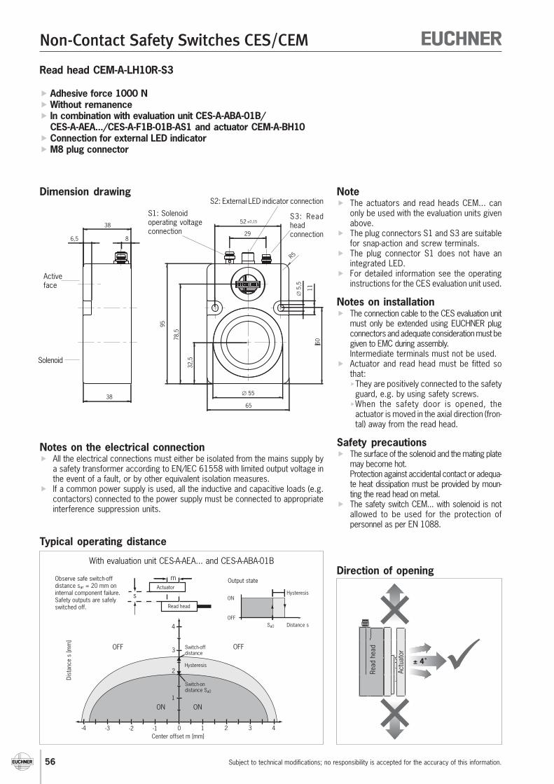
56
Non-Contact Safety Switches CES/CEM
Subject to technical modifications; no responsibility is accepted for the accuracy of this information.
Read head CEM-A-LH10R-S3
Note The actuators and read heads CEM... can
only be used with the evaluation units givenabove.
The plug connectors S1 and S3 are suitablefor snap-action and screw terminals.
The plug connector S1 does not have anintegrated LED.
For detailed information see the operatinginstructions for the CES evaluation unit used.
Notes on installation The connection cable to the CES evaluation unit
must only be extended using EUCHNER plugconnectors and adequate consideration must begiven to EMC during assembly.Intermediate terminals must not be used.
Actuator and read head must be fitted sothat:They are positively connected to the safety
guard, e.g. by using safety screws.When the safety door is opened, the
actuator is moved in the axial direction (fron-tal) away from the read head.
Safety precautions The surface of the solenoid and the mating plate
may become hot.Protection against accidental contact or adequa-te heat dissipation must be provided by moun-ting the read head on metal.
The safety switch CEM... with solenoid is notallowed to be used for the protection ofpersonnel as per EN 1088.
Dimension drawing
Adhesive force 1000 N Without remanence In combination with evaluation unit CES-A-ABA-01B/
CES-A-AEA.../CES-A-F1B-01B-AS1 and actuator CEM-A-BH10 Connection for external LED indicator M8 plug connector
Typical operating distance
Direction of opening
Notes on the electrical connection All the electrical connections must either be isolated from the mains supply by
a safety transformer according to EN/IEC 61558 with limited output voltage inthe event of a fault, or by other equivalent isolation measures.
If a common power supply is used, all the inductive and capacitive loads (e.g.contactors) connected to the power supply must be connected to appropriateinterference suppression units.
-4 -2-3 -1 1 32 40
1
2
3
4
Center offset m [mm]
Dist
ance
s [m
m]
OFF
ON
Hysteresis
Switch-ondistance Sa0
ON
OFF
Hysteresis
Distance sSa0
Output state
Switch-offdistance
OFF
Actuator
Read head
s
m
ON
Observe safe switch-offdistance sar = 20 mm oninternal component failure. Safety outputs are safelyswitched off.
With evaluation unit CES-A-AEA... and CES-A-ABA-01B
Read
hea
d
Actu
ator
± 4˚
S3: Readheadconnection29
52 ±0,15
∅ 5
,5
32,5
78,5
95
R
65
11
8
38
6,5
38
60
5
∅ 55
Activeface
Solenoid
S2: External LED indicator connection
S1: Solenoidoperating voltageconnection

57
Non-Contact Safety Switches CES/CEM
Subject to technical modifications; no responsibility is accepted for the accuracy of this information.
Ordering tableItem Adhesive force [N] Order No.CEM-A-LH10R-S3 1000 095 793
Technical dataParameters Value UnitGeneral min. typ. max.Housing material AluminumMaterial, read head CES Plastic (PPS)Solenoid material Galvanized steelWeight Approx. 0.9 kgAmbient temperature -25 - +50 °CDegree of protection according to IEC 60529 IP67Installation position AnySolenoidAdhesive force in axial direction 1000 NAdhesive force due to remanence Approx. 0.7 NSolenoid center offset max. ± 2.5 mmSolenoid operating voltage UB plug S1 20.4 24 26.4 V DCReverse polarity protection YesCurrent consumption at connection S1.2 (UB) 225 mAat connection S1.1 (MON) 15 (without external LED)Power consumption Approx. 5.8 WSwitch-off delay 750 msSolenoid operating voltage connection M8 plug connector (plug), 4-pinExternal LED indicator connection M8 plug connector (socket), 4-pinRead headOperating distance for center offset m = 0- Safe switch-off distance Sar - - 20Cable length l = 0 to 25 m- Switch-on distance Sa0 - 2 - mm- Switching hysteresis - 0.7 -Cable length l = 25 to 50 m- Switch-on distance Sa0 - 1.6 -- Switching hysteresis - 0.6 -Connection evaluation unit plug S3 M8 plug connector (plug), 3-pinConnection cable - - 50 mConnection external LED indicator plug S2Current consumption - - 500 mA
Pin assignment
2
1
4
3
S1 S3
1
4
3
4
3
2
1
S2
Solenoid operatingvoltage
S1.1 MON/ DC 24VS1.2 +UB/ DC 24VS1.3 0 V/GNDS1.4
Evaluation unitCES
S3.1 H1S3.3 H2S3.4 SH (screen)
S1/M8 plug S3/M8 plug
Circuit diagram connectionsolenoid operating voltage S1and external LED indicator S2
S2/M8 socket
External LEDindicator connectionS2.1 LED +UB
S2.2 -S2.3 LED 0 VS2.4 -
LED 0 V
LED +UB S2.1
S2.3
0 V
MEIN
+UB
S1.4
S1.2
S1.1
S1.3
µC
Sole
noid
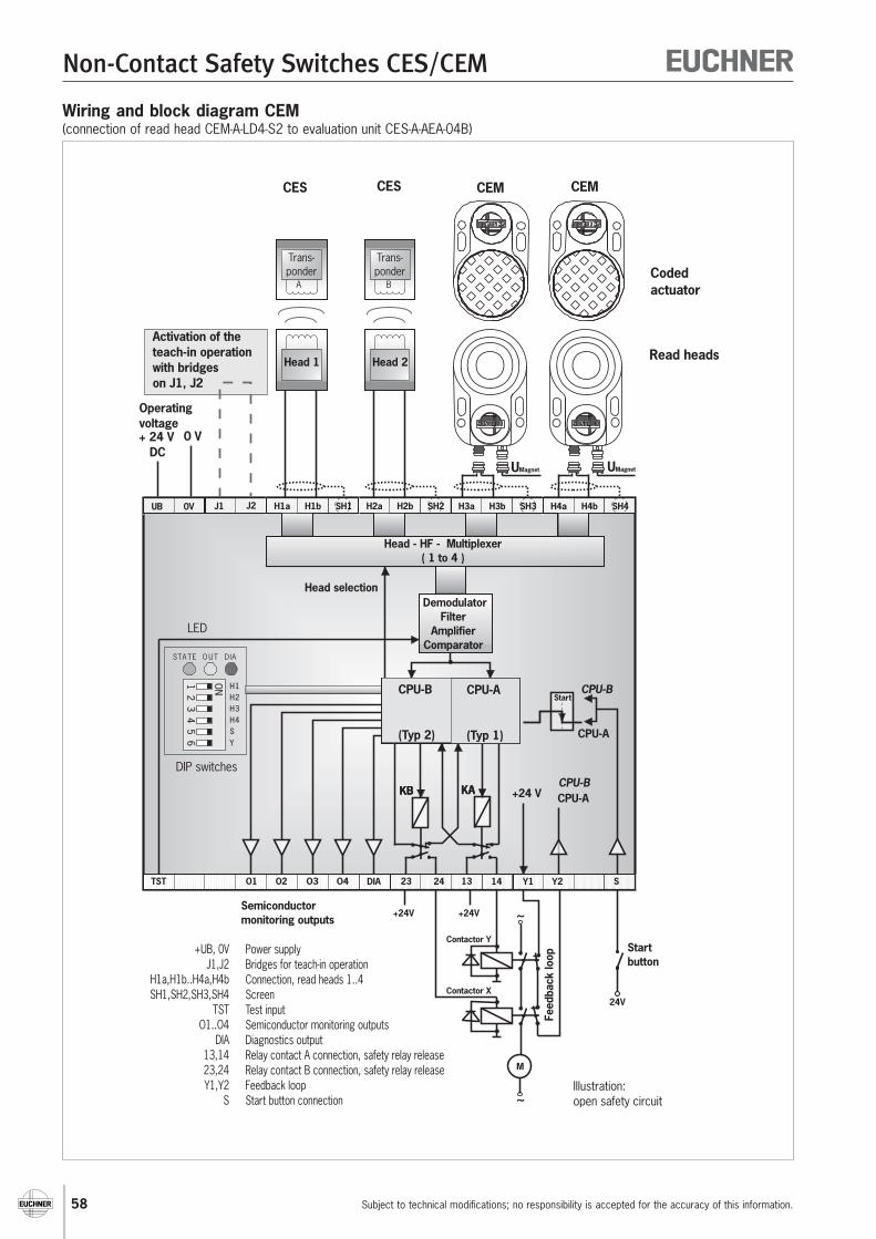
58
Non-Contact Safety Switches CES/CEM
Subject to technical modifications; no responsibility is accepted for the accuracy of this information.
Wiring and block diagram CEM(connection of read head CEM-A-LD4-S2 to evaluation unit CES-A-AEA-04B)
Read heads
Head - HF - Multiplexer( 1 to 4 )
+24V+24V
~
~
M
24V
Startbutton
Semiconductormonitoring outputs
Feed
back
loop
~
~
M
Codedactuator
Head 2Head 1
Trans-ponder
Trans-ponder
Trans-ponder
Trans-ponder
A B
+ 24 VDC
0 V
Operatingvoltage
UB
TST
0V
S
H1a H3aH2a H4aH1b H3bH2b H4bSH1 SH3SH2 SH4
O3 O4 DIA 141323 Y124 Y2
KAKB
J2J1
O1 O2
Head selection
+24 VKAKB
CPU-A(Typ 1)
CPU-A
(Typ 1)
CPU-B
CPU-B
CPU-A
CPU-A
StartStart
CPU-B(Typ 2)
CPU-B
(Typ 2)
DemodulatorFilter
AmplifierComparator
STA TE O UT DIA
LED
DIP switches
Activation of theteach-in operationwith bridgeson J1, J2
UMagnetUMagnet
CEM CEMCES CES
Contactor Y
Contactor X
+UB, 0VJ1,J2
H1a,H1b..H4a,H4bSH1,SH2,SH3,SH4
TSTO1..O4
DIA13,1423,24Y1,Y2
S
Power supplyBridges for teach-in operationConnection, read heads 1..4ScreenTest inputSemiconductor monitoring outputsDiagnostics outputRelay contact A connection, safety relay release
Feedback loopStart button connection
Relay contact B connection, safety relay releaseIllustration:open safety circuit
YSH4H3H2H1
ON12
34
56
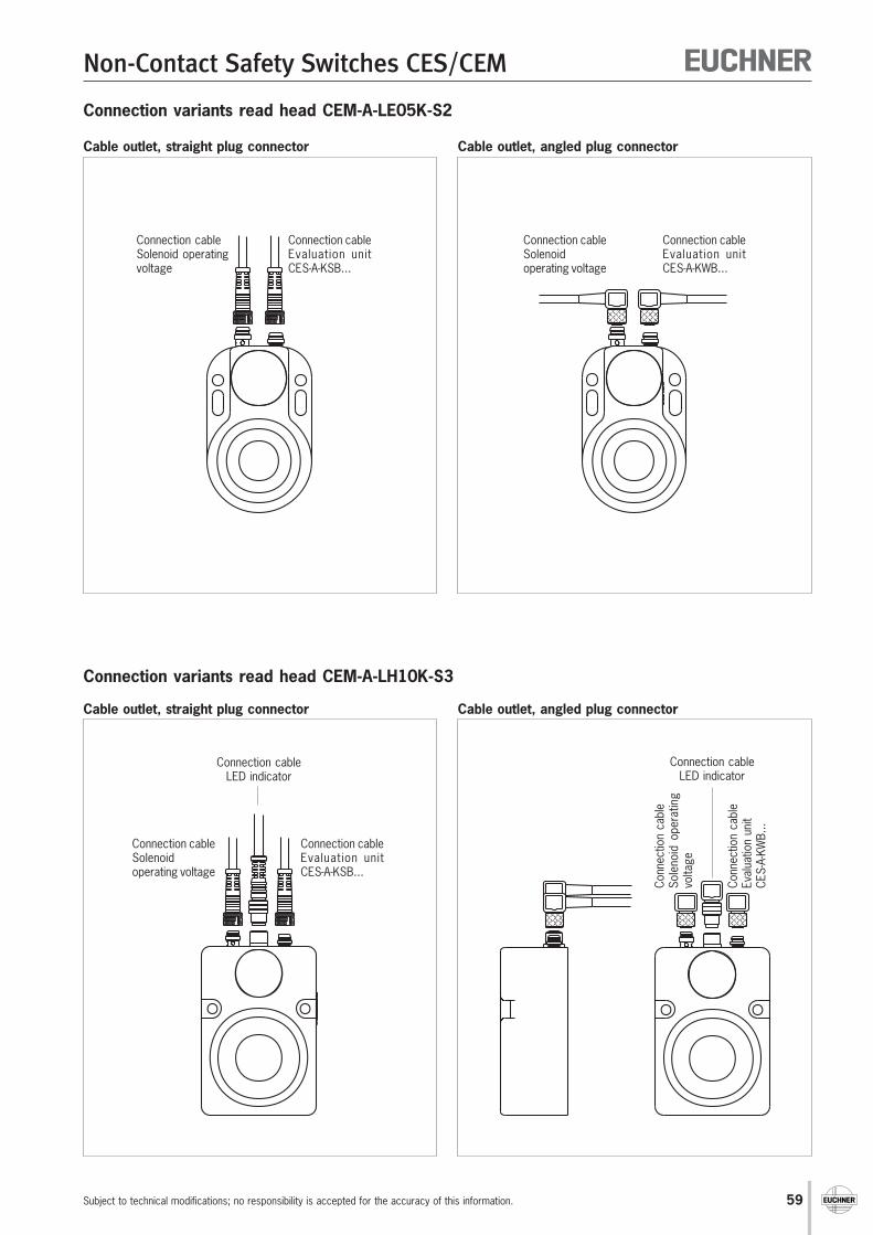
59
Non-Contact Safety Switches CES/CEM
Subject to technical modifications; no responsibility is accepted for the accuracy of this information.
Connection variants read head CEM-A-LE05K-S2
Cable outlet, straight plug connector Cable outlet, angled plug connector
Connection variants read head CEM-A-LH10K-S3
Cable outlet, straight plug connector Cable outlet, angled plug connector
Connection cableSolenoidoperating voltage
Connection cableEvaluation unitCES-A-KWB...
Connection cableSolenoid operatingvoltage
Connection cableEvaluation unitCES-A-KSB...
Conn
ectio
n ca
ble
Sole
noid
ope
ratin
gvo
ltage
Conn
ectio
n ca
ble
Eval
uatio
n un
itCE
S-A-
KWB.
..Connection cable
LED indicator
Connection cableSolenoidoperating voltage
Connection cableEvaluation unitCES-A-KSB...
Connection cableLED indicator
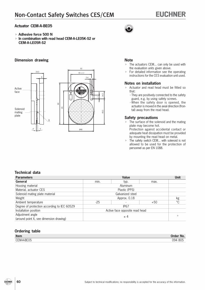
60
Non-Contact Safety Switches CES/CEM
Subject to technical modifications; no responsibility is accepted for the accuracy of this information.
Note The actuators CEM... can only be used with
the evaluation units given above. For detailed information see the operating
instructions for the CES evaluation unit used.
Notes on installation Actuator and read head must be fitted so
that:They are positively connected to the safety
guard, e.g. by using safety screws.When the safety door is opened, the
actuator is moved in the axial direction (fron-tal) away from the read head.
Safety precautions The surface of the solenoid and the mating
plate may become hot.Protection against accidental contact oradequate heat dissipation must be providedby mounting the read head on metal.
The safety switch CEM... with solenoid is notallowed to be used for the protection ofpersonnel as per EN 1088.
Dimension drawing
Actuator CEM-A-BE05
Adhesive force 500 N In combination with read head CEM-A-LE05K-S2 or
CEM-A-LE05R-S2
50
40 ±0,10
5,4
80
65
Ø48
49,5
7 14,5
4˚ 4˚
8
24,5
X
Activeface
Solenoidmatingplate
Technical dataParameters Value UnitGeneral min. typ. max.Housing material AluminumMaterial, actuator CES Plastic (PPS)Solenoid mating plate material Galvanized steelWeight Approx. 0.18 kgAmbient temperature -25 - +50 °CDegree of protection according to IEC 60529 IP67Installation position Active face opposite read headAdjustment angle ± 4 °(around point X, see dimension drawing)
Ordering tableItem Order No.CEM-A-BE05 094 805
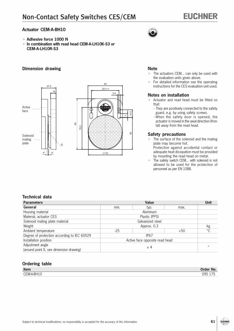
61
Non-Contact Safety Switches CES/CEM
Subject to technical modifications; no responsibility is accepted for the accuracy of this information.
Note The actuators CEM... can only be used with
the evaluation units given above. For detailed information see the operating
instructions for the CES evaluation unit used.
Notes on installation Actuator and read head must be fitted so
that:They are positively connected to the safety
guard, e.g. by using safety screws.When the safety door is opened, the
actuator is moved in the axial direction (fron-tal) away from the read head.
Safety precautions The surface of the solenoid and the mating
plate may become hot.Protection against accidental contact oradequate heat dissipation must be providedby mounting the read head on metal.
The safety switch CEM... with solenoid is notallowed to be used for the protection ofpersonnel as per EN 1088.
Dimension drawing
Actuator CEM-A-BH10
Adhesive force 1000 N In combination with read head CEM-A-LH10K-S3 or
CEM-A-LH10R-S3
52 ±0,15
65
5,4
95
78,5
60
7 14,5
∅ 634° 4°
27,5
10
X
Activeface
Technical dataParameters Value UnitGeneral min. typ. max.Housing material AluminumMaterial, actuator CES Plastic (PPS)Solenoid mating plate material Galvanized steelWeight Approx. 0.3 kgAmbient temperature -25 - +50 °CDegree of protection according to IEC 60529 IP67Installation position Active face opposite read headAdjustment angle ± 4 °(around point X, see dimension drawing)
Ordering tableItem Order No.CEM-A-BH10 095 175
Solenoidmatingplate
62
Non-Contact Safety Switches CES/CEM
Subject to technical modifications; no responsibility is accepted for the accuracy of this information.
AccessoriesConnection cable with M8 plug connector for solenoid operating voltage on read head CEM...
M8 female connectorCrimped ferrules
Angled plug connector
Technical dataParameters ValuePlug connector 4-pin M8 female connector, screw terminals
Plug housing, black PURUnion nut, nickel-plated CuZn
Connection cable 4 x 0.25 mm² screened, ∅ 5.0 mm, outer sheath PVCBending radius 70 mm min.
Straight plug connector
M8 female connector
Crimped ferrules
Ordering table
Plug connector Cable length "l" Cable type Order No.(meters) V=PVC
-05 V 088 813straight -10 V 088 814
-15 V 088 815-25 V 095 035
angled -10 V 084 703
"l"
∅5
31
22,5∅
1030
4 (BK) 2 (WH)
1 (BN)3 (BU)
View of connection side
"l"
∅5
30
10
18,5
26,5
∅10
8
6
1 (BN)
2 (WH)4 (BK)
3 (BU)
View of connection side

63
Non-Contact Safety Switches CES/CEM
Subject to technical modifications; no responsibility is accepted for the accuracy of this information.
Connection cable with M8 plug connector for LED indicator on read head CEM-A-LH10K-S3
Technical dataParameters ValuePlug connector 4-pin M8 plug, straight, screw terminals
Plug housing, black PURUnion nut, nickel-plated CuZn
Connection cable 4 x 0.25 mm² screened, ∅ 5.0 mm, outer sheath PVCBending radius 70 mm min.
Ordering table
Plug connector Cable length "l" Cable type Order No.(meters) V=PVC
-02 V 088 841
straight -05 V 088 842-10 V 088 843-15 V 088 844
angled -10 V 084 705
M8 plugCrimped ferrules
Straight plug connector
"l"
3037
31
M8x
1
4 (BK)2 (WH)
1 (BN) 3 (BU)
View of connection side
Angled plug connector
M8 plug
Crimped ferrules
View of connection side "l"
50
M8x1
13,624
,85
26,526,5
4 (BK)2 (WH)
1 (BN) 3 (BU)
8,8

64
Non-Contact Safety Switches CES/CEM
Subject to technical modifications; no responsibility is accepted for the accuracy of this information.
"l"
∅4,
6
31
22,5
∅10
30
Connection cable with M8 plug connector for read head CES-A-L... and CEM-A-L
M8 female connectorCrimped ferrules
Ordering table
Plug connector Cable length "l" Cable type Type designation Order No.(meters) V=PVC / P=PUR
-03 V CES-A-KSB-03V 077 935-05 V CES-A-KSB-05V 077 793-10 V CES-A-KSB-10V 077 767-20 V CES-A-KSB-20V 077 716-25 V CES-A-KSB-25V 077 717-50 V CES-A-KSB-50V 077 718
straight -05 P CES-A-KSB-05P 084 762-10 P CES-A-KSB-10P 084 763-15 P CES-A-KSB-15P 084 764-20 P CES-A-KSB-20P 084 765-25 P CES-A-KSB-25P 084 766-50 P CES-A-KSB-50P 084 767
angled -10 V CES-A-KWB-10V 084 701
Technical dataParameters ValuePlug connector 3-pin M8 female connector, straight
Screw terminalsKnurled nut not connected to cable screen
Connection cable 2 x 0.25 mm² screened, ∅ 4.6 mm, outer sheath PVC2 x 0.25 mm² screened, ∅ 4.8 mm, outer sheath PUR,
suitable for drag chainCable length max. 50 m
taking into account the switching distance
Angled plug connector
M8 female connector
Crimped ferrules
"l"
∅4,
6
30
10
18,5
26,5
∅10

65
Non-Contact Safety Switches CES/CEM
Subject to technical modifications; no responsibility is accepted for the accuracy of this information.
1 = WH 0 V2 = BN + UB3 = GN LA4 = YE LB5 = GY OUT6 = PK +LA7 = BU -LAB8 = RD +LB
∅6
∅14
"l"8
3
5
7
4
2 1
6
Connection cable with M12 plug connector for safety switch CES-A-C5...
Ordering tableCable length "l" Order No.
5 m 077 75110 m 077 75215 m 077 75320 m 077 87125 m 077 87250 m 077 873
View on connection side of the8-pin female connector
Safety switch CES-A-C5...Voltage drop as a function of switching current and cable length (examples)
Switching current Cable length "l" Voltage drop Max. voltage drop Max. voltage drop[mA] [m] Output [V] Cable [V] Total [V]
6 1 - 100 1.4 0.1 1.5(safety controlsystem with 101 - 300 1.4 0.4 1.8
pulsed signals)1 - 15 1.5 0.2 1.7
50 16 - 50 1.5 0.5 2.0(safety relay) 51 - 100 1.5 1.0 2.5
101 - 300 1.5 3.0 3.51 - 15 1.7 1.2 2.9
400 16 - 50 1.7 4.0 5.7(e.g. small contactor) 51 - 100 1.7 8.0 9.7
101 - 300 1.7 – –
Technical dataParameters ValuePlug connector 8-pin M12 female connector, straight
Screw terminalsKnurled nut electrically connected to cable screen
Connection cable 8 x 0.25 mm² screenedOuter sheath PVC
Cable length Max. 300 mTaking into account the voltage drop due
to the cable resistance (see table)

66
Non-Contact Safety Switches CES/CEM
Subject to technical modifications; no responsibility is accepted for the accuracy of this information.
∅19
Pg9
∅19
,5
Pg9
SW16SW1644
106
62
12
3
Plug connector for read head CES-A-L...
Using EUCHNER couplings / plug connectors, the user can cut the read head cable to size on site at any point and connect thecouplings / plug connectors.
NoteThe connection cable for the read head can only be extended using these self-assembly couplings / plug connectors under thefollowing conditions: The total maximum cable length is 50 m, taking into account the switch-on distance. The cable specified by EUCHNER must be used for the extension (screened, conductor cross-section 2 x 0.25 mm²). The plug connector housing must be electrically isolated from the machine ground.
Coupling socketKD4C1851
Female connectorBS4C1851
ViewTerminal side
Female connector
Inserted
1 = BN H13 = WH H2Plug housing SH(Screen)
Technical dataParameters ValueHousing material CuZn, matt chromium-platedDegree of protection according IP 65to EN 60529 (inserted)
Ordering tableItem Order No.Flange socket KD4C1851 077 434Female connector BS4C1851 077 435
12,3 +0,12-0,06
11,1 +0,12-0,06
15
1,5
t = 0,6
Safety screws
Screw type Use Packaging unit Type Order No.for read head CES-A-L...
M4x14 for read head CES-A-B... 20 pieces M4x14-CES/V20 071 863for actuator CES-A-BBA
Insertion tool for actuator CES-A-BMB
With the aid of the insertion tool, the actuator CES-A-BMB (cylindrical design) can be screwed into a prepared M12 x 0.75 thread insafety doors.
Ordering tableItem Order No.Insertion tool for actuator CES-A-BMB 037 662
Plug connector for safety switch CES-A-S5...
Item Order No.Plug connector for safety switch CES-A-S5... 096 490
67
Non-Contact Safety Switches CES/CEM
Subject to technical modifications; no responsibility is accepted for the accuracy of this information.
Appendix Definition of terms Index
Door monitoring output The door monitoring output is not a safety-related output; it may not be connected to thesafety circuit. The door monitoring output is generally connected to a higher-level controlsystem to indicate the position of the doors (open/closed) on a visual display.
Dwell time The dwell time is the time that the actuator must be inside or outside the operating distance.
Fault detection time The fault detection time is the time for the detection of an internal fault in the device. At leastone of the relay outputs is opened safely. The welding of one of the relay contacts is onlydetected after the safety guard is opened.
PDF Proximity device with defined behavior under fault conditions (see EN 60 947-5-3).
PDF-M PDF proximity devices with automatic control that do not lose their defined behavior in spite ofseveral faults (see EN 60 947-5-3).
PDF-S PDF proximity devices that do not lose their defined behavior in spite of a single fault (see EN60947 5 3).
Safety class III Equipment of safety class III is equipment on which protection against electric shock is basedon safety extra-low voltage and is equipment in which no voltages higher than the safety extra-low voltage are produced.
Safety extra-low voltage Voltage of a magnitude that does not pose an immediate risk to people. It provides safeelectrical isolation from higher voltage power circuits and is used isolated from ground.
Safety output The safety output is a safety-related output that may be connected to the safety circuit. Asafety output can be switched via relay contacts or semiconductor elements.
Sar Assured switch-off distance Sar
Distance from the active face within which the correct detection of the absence of a definedobject is achieved under all defined environmental conditions, manufacturer's tolerances andinternal component faults.
Sa0 Assured switch-on distance Sa0
Distance from the active face within which the correct detection of the presence of a definedobject is achieved under all defined environmental conditions and manufacturer's tolerances.
Switching delay fromstate change Corresponds to the risk time according to EN 60947-5-3. This is the maximum switch-off delay
for the safety outputs following removal of the actuator.
Definition of terms
68
Non-Contact Safety Switches CES/CEM
Subject to technical modifications; no responsibility is accepted for the accuracy of this information.
Item Order No. Page
Index sorted by article
Item Order No. PageCEM-A-LH10K-S3 095 170 55CEM-A-LH10R-S3 095 793 57CES-A-ABA-01 071 850 11CES-A-ABA-01B 083 513 11CES-A-AEA-02B 092 560 17CES-A-AEA-04B 072 000 19CES-A-BBA 071 840 44CES-A-BCA 088 786 44CES-A-BDA 084 720 46CES-A-BMB 077 791 47CES-A-C5E-01 077 750 27CES-A-C5H-01 091 458 27CES-A-KSB-03V 077 935 64CES-A-KSB-05P 084 762 64CES-A-KSB-05V 077 793 64CES-A-KSB-10P 084 763 64CES-A-KSB-10V 077 767 64CES-A-KSB-15P 084 764 64CES-A-KSB-20P 084 765 64CES-A-KSB-20V 077 716 64CES-A-KSB-25P 084 766 64CES-A-KSB-25V 077 717 64CES-A-KSB-50P 084 767 64CES-A-KSB-50V 077 718 64CES-A-KWB-10V 084 701 64CES-A-LCA-10V 088 785 41CES-A-LMN-SC 077 790 43CES-A-LNA-05P 077 806 37CES-A-LNA-05V 071 845 37CES-A-LNA-10P 077 807 37CES-A-LNA-10V 071 846 37CES-A-LNA-15P 084 682 37CES-A-LNA-15V 071 847 37CES-A-LNA-25V 071 975 37CES-A-LNA-50V 077 795 37CES-A-LNA-SC 077 715 39CES-A-NBA-2 090 682 45CES-A-NBA-3 090 683 45CES-A-NBA-4 090 684 45CES-A-NBA-5 090 685 45CES-A-NBA-6 090 686 45CES-A-NBA-7 090 687 45CES-A-NBA-8 090 688 45CES-A-NBA-9 090 689 45CES-A-NBA-A 090 690 45CES-A-NBA-B 090 691 45CES-A-NBA-C 090 692 45CES-A-NBA-D 090 693 45CES-A-NBA-E 090 694 45CES-A-NBA-F 090 695 45CES-A-S5H-01 090 640 33Connection cable M8 for LED indicator read head
084 705 63CEM-A-LH10K-S3, plug connector, angled, length 10 mConnection cable M8 for LED indicator read head 088 841 63CEM-A-LH10K-S3, plug connector, straight, length 2 mConnection cable M8 for LED indicator read head
088 842 63CEM-A-LH10K-S3, plug connector, straight, length 5 mConnection cable M8 for LED indicator read head
088 843 63CEM-A-LH10K-S3, plug connector, straight, length 10 mConnection cable M8 for LED indicator read head
088 844 63CEM-A-LH10K-S3, plug connector, straight, length 15 mConnection cable M8 for solenoid operating voltage C
084 703 62EM, plug connector, angled, length 10 mConnection cable M8 for solenoid operating voltage
088 813 62CEM, plug connector, straight, length 5 mConnection cable M8 for solenoid operating voltage
088 814 62CEM, plug connector, straight, length 10 mConnection cable M8 for solenoid operating voltage
088 815 62CEM, plug connector, straight, length 15 m
Connection cable M8 for solenoid operating voltage095 035 62CEM, plug connector, straight, length 25 m
Connection cable M12 for CES-A-C5... length 5 m 077 751 65Connection cable M12 for CES-A-C5... length 10 m 077 752 65Connection cable M12 for CES-A-C5... length 15 m 077 753 65Connection cable M12 for CES-A-C5... length 20 m 077 871 65Connection cable M12 for CES-A-C5... length 25 m 077 872 65Connection cable M12 for CES-A-C5... length 50 m 077 873 65Flange socket KD4C1851 077 434 66Insertion tool for actuator CES-A-BMB 037 662 66Plug connector for safety switch CES-A-S5... 096 490 66Safety screws M4x14-CES/V20 071 863 66

69
Non-Contact Safety Switches CES/CEM
Subject to technical modifications; no responsibility is accepted for the accuracy of this information.
Index sorted by catalog number
Order No. Item Page Order No. Item Page037 662 Insertion tool for actuator CES-A-BMB 66071 840 CES-A-BBA 44071 845 CES-A-LNA-05V 37071 846 CES-A-LNA-10V 37071 847 CES-A-LNA-15V 37071 850 CES-A-ABA-01 11071 863 Safety screws M4x14-CES/V20 66071 975 CES-A-LNA-25V 37072 000 CES-A-AEA-04B 19077 434 Flange socket KD4C1851 66077 715 CES-A-LNA-SC 39077 716 CES-A-KSB-20V 64077 717 CES-A-KSB-25V 64077 718 CES-A-KSB-50V 64077 750 CES-A-C5E-01 27077 751 Connection cable M12 for CES-A-C5... length 5 m 65077 752 Connection cable M12 for CES-A-C5... length 10 m 65077 753 Connection cable M12 for CES-A-C5... length 15 m 65077 767 CES-A-KSB-10V 64077 790 CES-A-LMN-SC 43077 791 CES-A-BMB 47077 793 CES-A-KSB-05V 64077 795 CES-A-LNA-50V 37077 806 CES-A-LNA-05P 37077 807 CES-A-LNA-10P 37077 871 Connection cable M12 for CES-A-C5... length 20 m 65077 872 Connection cable M12 for CES-A-C5... length 25 m 65077 873 Connection cable M12 for CES-A-C5... length 50 m 65077 935 CES-A-KSB-03V 64083 513 CES-A-ABA-01B 11084 682 CES-A-LNA-15P 37084 701 CES-A-KWB-10V 64
084 703 Connection cable M8 for solenoid operating voltage62CEM, plug connector, angled, length 10 m
084 705 Connection cable M8 for LED indicator read head63CEM-A-LH10K-S3, plug connector, angled, length 10 m
084 720 CES-A-BDA 46084 762 CES-A-KSB-05P 64084 763 CES-A-KSB-10P 64084 764 CES-A-KSB-15P 64084 765 CES-A-KSB-20P 64084 766 CES-A-KSB-25P 64084 767 CES-A-KSB-50P 64088 785 CES-A-LCA-10V 41088 786 CES-A-BCA 44
088 813 Connection cable M8 for solenoid operating voltage62CEM, plug connector, straight, length 5 m
088 814 Connection cable M8 for solenoid operating voltage62CEM, plug connector, straight, length 10 m
088 815 Connection cable M8 for solenoid operating voltage62CEM, plug connector, straight, length 15 m
088 841 Connection cable M8 for LED indicator read head63CEM-A-LH10K-S3, plug connector, straight, length 2 m
088 842 Connection cable M8 for LED indicator read head63CEM-A-LH10K-S3, plug connector, straight, length 5 m
088 843 Connection cable M8 for LED indicator read head63CEM-A-LH10K-S3, plug connector, straight, length 10 m
088 844 Connection cable M8 for LED indicator read head63CEM-A-LH10K-S3, plug connector, straight, length 15 m
090 687 CES-A-NBA-7 45090 640 CES-A-S5H-01 33090 682 CES-A-NBA-2 45090 683 CES-A-NBA-3 45090 684 CES-A-NBA-4 45090 685 CES-A-NBA-5 45090 686 CES-A-NBA-6 45090 688 CES-A-NBA-8 45090 689 CES-A-NBA-9 45090 690 CES-A-NBA-A 45
090 691 CES-A-NBA-B 45090 692 CES-A-NBA-C 45090 693 CES-A-NBA-D 45090 694 CES-A-NBA-E 45090 695 CES-A-NBA-F 45091 458 CES-A-C5H-01 27092 560 CES-A-AEA-02B 17
095 035Connection cable M8 for solenoid operating voltage
62CEM, plug connector, straight, length 25 m095 170 CEM-A-LH10K-S3 55095 793 CEM-A-LH10R-S3 57096 490 Plug connector for safety switch CES-A-S5... 66

70
ItalyTRITECNICA S.r.l.Viale Lazio 2620135 MilanoTel. +39-02-5419-41Fax [email protected]
JapanSolton Co. Ltd.2-13-7, Shin-YokohamaKohoku-ku, YokohamaJapan 222-0033Tel. +81-(0)45-471-7711Fax +81-(0)[email protected]
KoreaEUCHNER Korea Co., Ltd.RM 810 Daerung Technotown 3rd#448 Gasang-DongKumchon-Gu, SeoulTel. +82-(02)-2107-3500Fax +82-(02)[email protected]
MexicoSEPIA S.A. de C.V.Maricopa # 10302, Col. Napoles.Del. Benito Juarez03810 Mexico D.F.Tel. +52-55-5536-7787Fax [email protected]
New ZealandW Arthur Fisher Limited11 Te Apunga PlaceMt WellingtonAucklandTel. +64-(0)9270-0100Fax +64-(0)[email protected]
NorwayELIS ELEKTRO ASJerikoveien 161067 OsloTel. +47-22-9056-70Fax [email protected]
PolandELTRONPl. Wolnosci 7B50-071 WroclawTel. +48-(0)71-3439-755Fax +48-(0)[email protected]
PortugalPAM Serviços Tecnicos Industriais Lda.Rua de Timor - Pavilhão 2AZona Industrial da Abelheira4785-123 TROFATel. +351-252-418431Fax [email protected]
SingaporeSentronics Automation & Marketing Pte Ltd.Blk 3, Ang Mo Kio Industrial Park 2A#05-06Singapore 568050Tel. +65-6744-8018Fax [email protected]
RRRRRepreprepreprepreeeeesentsentsentsentsentation intation intation intation intation internernernernernationationationationationalalalalal
AustraliaMicromax Pty. Ltd.PO Box 1238Wollongong NSW 2500Tel. +61-(0)2-4271-1300Fax +61-(0)[email protected]
AustriaEUCHNER Ges.mbHSüddruckgasse 42512 TribuswinkelTel. +43-(0)2252-421-91Fax +43-(0)[email protected]
BeneluxEUCHNER (BENELUX) BVPostbus 1193350 AC PapendrechtTel. +31-(0)78-6154-766Fax +31-(0)[email protected]
BrazilEUCHNER LtdaAv. Prof. Luiz Ignácio Anhaia Mello,no. 4387S. LucasSão Paulo - SP - BrasilCEP 03295-000Tel. +55-11-6918-2200Fax [email protected]
CanadaIAC & Associates Inc.1925 Provincial RoadWindsor, OntarioN8W 5V7Tel. +01-519-966-3444Fax [email protected]
ChinaEUCHNER Electric (Shanghai) Ltd.No. 8 High Technology ZoneNo. 503 Meinengda RoadSongjiang, Shanghai, 201613Tel. +86-(0)21-5774-7090Fax +86-(0)[email protected]
KNOWHOW I&C Co.C-2204 Webok Time CenterNo. 17 Zhongguancun NandajieBeijing, 100081Tel. +86-(0)10-8857-8899Fax +86-(0)[email protected]
Czech RepublicAMTEK s.r.o.Videnská 125619 00 BrnoTel. +420-547-125-570Fax [email protected]
DenmarkRobotek El & Teknik A/SBlokken 313460 BirkerødTel. +45-4484-7360Fax [email protected]
Eastern EuropeHera Elektrotechnische ProdukteHandels Ges.mbHHauptstraße 612391 KaltenleutgebenTel. +43-(0)2238-77518Fax +43-(0)[email protected]
FinlandSähkölehto OyHolkkitie 1400880 HelsinkiTel. +358-(0)9-774-6420Fax +358-(0)[email protected]
FranceEUCHNER France S.A.R.L.Parc d'Affaires des BellevuesRue Rosa LuxembourgBâtiment le Colorado95610 ERAGNY sur OISETel. +33-(0)1-3909-9090Fax +33-(0)[email protected]
Hong KongImperial Engineers & Equipment Co. Ltd.Unit B 12/F Cheung Lee Industrial Building9 Cheung Lee Street Chai WanHong KongTel. +852-2889-0292Fax [email protected]
HungaryEUCHNER Ges.mbHMagyarországi Fióktelep2045 TörökbálintTópark utca 1/a.Tel. +36-2342-8374Fax [email protected]
IndiaTEKNIC CONTROLGEAR PVT. LTD.703, Madhava,Bandra Kurla ComplexBandra (East)Mumbai 400051Tel. +91-(0)22-2659-2392Fax +91-(0)[email protected]
IranINFOCELL IRAN CO.# 84, Manoucheri Ave.P.O. Box 81655-861IsfahanTel. +98-(0)311-2211-358Fax +98-(0)[email protected]
SloveniaSMM d.o.o.Jaskova 182000 MariborTel. +386-(0)2450-2326Fax +386-(0)[email protected]
SpainEUCHNER, S.L.U.Gurutzegi 12 - Local 1Polígono Belartza20018 San SebastianTel. +34-943-316-760Fax [email protected]
SwedenCensit ABBox 33133123 VärnamoTel. +46-(0)370-6910-10Fax +46-(0)[email protected]
SwitzerlandEUCHNER AGGrofstraße 178887 MelsTel. +41-(0)81-720-4590Fax +41-(0)[email protected]
TaiwanDaybreak Int'l (Taiwan) Corp.3F, No. 124, Chung-Cheng RoadShihlin 11145, TaipeiTel. +886-(0)2-8866-1234Fax +886-(0)[email protected]
ThailandAero Automation Co., Ltd.600/441 Moo 14 Phaholyothin Rd.Kukot, LamlukkaPatumthanee 12130Tel. +66-(0)2-536-7660-1Fax +66-(0)[email protected]
TurkeyARI Endustri Urunleri SAN. Ve Tic.Ltd.Sti.Perpa Ticaret MerkeziA Blok Kat 11 No:140634384 Okmeydani/Sisli IstanbulTel. +90-(0)212-3204-334Fax +90-(0)[email protected]
United KingdomEUCHNER (UK) Ltd.Unit 2 Petre Drive,SheffieldSouth YorkshireS4 7PZTel. +44-(0)114-256-0123Fax +44-(0)[email protected]
USAEUCHNER USA Inc.6723 Lyons StreetEast Syracuse, NY 10357Tel. +01-315-7010-315Fax [email protected]
´´
ˆ

71
wwwwwwwwwwwwwww.....euceuceuceuceuchnerhnerhnerhnerhner.....cccccomomomomom
HeHeHeHeHeaaaaad officd officd officd officd officeeeee
EUCHNER GmbH + Co. KGKohlhammerstraße 1670771 Leinfelden-EchterdingenGermanyTel. +49-(0)711-7597-0Fax +49-(0)[email protected]
More than safety. More than safety. Morthan safety. More than safety. More thansafety. More than safety. More than safeMore than safety. More than safety. Morthan safety. More than safety. More thansafety. More than safety. More than safeMore than safety. More than safety. Morthan safety. More than safety. More thansafety. More than safety. More than safeMore than safety. More than safety. Morthan safety. More than safety. More thansafety. More than safety. More than safeMore than safety. More than safety. Morthan safety. More than safety. More thansafety. More than safety. More than safeMore than safety. More than safety. Morthan safety. More than safety. More thansafety. More than safety. More than safeMore than safety. More than safety. Morthan safety. More than safety. More thansafety. More than safety. More than safeMore than safety. More than safety. Morthan safety. More than safety. More thansafety. More than safety. More than safeMore than safety. More than safety. Morthan safety. More than safety. More thansafety. More than safety. More than safeMore than safety. More than safety. Morthan safety. More than safety. More thansafety. More than safety. More than safeMore than safety. More than safety. Morthan safety. More than safety. More thansafety. More than safety. More than safeMore than safety. More than safety. Morthan safety. More than safety. More thansafety. More than safety. More than safeMore than safety. More than safety. Morthan safety. More than safety. More thansafety. More than safety. More than safeMore than safety. More than safety. Morthan safety. More than safety. More thansafety. More than safety. More than safeMore than safety. More than safety. Morthan safety. More than safety. More thansafety. More than safety. More than safeMore than safety. More than safety. Mor
More than safety.than safety. Moresafety. More thanMore than safety.than safety. Moresafety. More thanMore than safety.than safety. Moresafety. More thanMore than safety.than safety. Moresafety. More thanMore than safety.than safety. Moresafety. More thanMore than safety.than safety. Moresafety. More thanMore than safety.than safety. Moresafety. More thanMore than safety.than safety. Moresafety. More thanMore than safety.than safety. Moresafety. More thanMore than safety.than safety. Moresafety. More thanMore than safety.than safety. Moresafety. More thanMore than safety.than safety. Moresafety. More thanMore than safety.than safety. Moresafety. More thanMore than safety.than safety. Moresafety. More thanMore than safety.than safety. Moresafety. More thanMore than safety.
Automation
Safety
ManMachine