nomographs and feasibility graphs for enumeration...
TRANSCRIPT

Hindawi Publishing CorporationAdvances in Mechanical EngineeringVolume 2013, Article ID 120324, 15 pageshttp://dx.doi.org/10.1155/2013/120324
Research ArticleNomographs and Feasibility Graphs for Enumeration ofRavigneaux-Type Automatic Transmissions
Essam L. Esmail
College of Engineering, University of Qadisiyah, Al Qadisiyah, Iraq
Correspondence should be addressed to Essam L. Esmail; [email protected]
Received 12 October 2012; Revised 5 January 2013; Accepted 12 January 2013
Academic Editor: Marco Ceccarelli
Copyright © 2013 Essam L. Esmail. This is an open access article distributed under the Creative Commons Attribution License,which permits unrestricted use, distribution, and reproduction in any medium, provided the original work is properly cited.
Although there are many epicyclic-type automatic transmissions in production, the related configuration design methods arestill tedious and borne to human error. A simple methodology for the systematic design of the Ravigneaux-type epicyclicgear transmissions needs to be developed. First, fundamentals and gear-shifting of four-speed and six-speed epicyclic-typeautomatic transmissions are illustrated to establish the design requirements. Second, based on the kinematic nomographs ofthe corresponding basic gear ratios, a simple clutching-sequence method is proposed and illustrated. Next, a planar-graphrepresentation is presented to arrange the desired clutches for each possible clutching sequence into the epicyclic gear mechanism.Then, with the above methods, the systematic designs of the epicyclic gear mechanisms are given for demonstrating the feasibilityof the proposed methodology. The result of this work shows that the seven-, eight-, and nine-link two-DOF Ravigneaux-typeepicyclic gear mechanisms could reach four-, six-, and eight-forward speeds at most, respectively. New five-, six-, seven-, andeight-velocity automatic transmissions are enumerated from the two-ring eight- and nine-link Ravigneaux gear mechanisms. It isa major breakthrough to design completely satisfactory eight-speed automatic transmissions from the nine-link Ravigneaux gearmechanism.
1. Introduction
For a long-time automatic transmissions with planetary geartrains are used in the automotive industry. Ravigneaux in1940 proposed seven- and eight-link two-degree-of-freedom(DOF) epicyclic gear mechanisms [1, 2]. These epicyclic gearmechanisms are called the Ravigneaux gear mechanisms.Figure 1 shows an automatic transmission which providesthree forward speeds and one reverse speed [3]. It consistsof a seven-link two-DOF Ravigneaux gear mechanism, tworotating clutches C
1and C
2, and two band clutches B
1and
B3. In the associated clutching sequence Table, X
𝑖indicates
that the corresponding clutch is activated on the 𝑖th link forthat gear.The ranges of output velocities are classified into twokinds: under drive (UD) and reverse drive (RD) according towhether the velocity is between zero and the input velocity,or less than zero. A “direct drive” (DD) is equal to the inputvelocity.
The seven-link two-DOF-Ravigneaux gear train has beendeveloped by nearly all automotive manufacturers as three-
or four-velocity automatic transmission [3]. It can be foundin Ford C
3, Ford C
5, Mercedes Benz, Toyota A40, andNissan,
to name, a few three-velocity automatic transmissions. It canalso be found in KM 175 and 176, Ford AOD, ZF 4 HP 14,and Borg-Warner [4], to name, a few four-velocity automatictransmissions [5]. Figure 2 shows the ZF 4 HP 14 automatictransmission [6], which can provide four forward speeds andone reverse speed.
Sometimes, the seven-link two-DOF Ravigneaux geartrain is integrated with a simple epicyclic gear train to formten-link three-DOF epicyclic gear mechanisms to enhancethe number of speeds [6, 7], providing six forward speeds.Figure 3 shows Lepelletier automatic transmission and itsclutching sequence table [8]. A widespread gear set concept isthat of Lepelletier. This design is based on a single planetarygear set with rear-mounted Ravigneaux gear set. In 2003,ZF [9] used this gear set design to bring the first 6-speedpassenger car transmission 6 HP 26 on themarket (Figure 3).
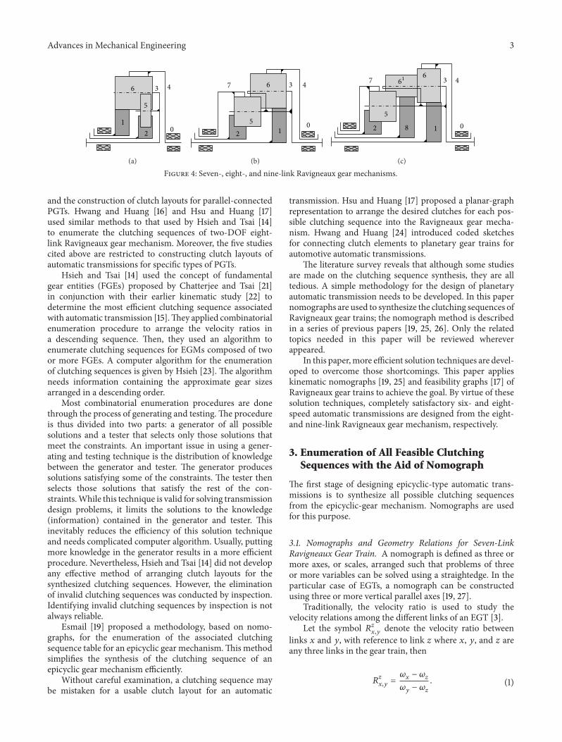
Two-DOF eight-link Ravigneaux gear mechanism,shown in Figure 4(b), consists of a long pinion and two

2 Advances in Mechanical Engineering
Engine
C1C2C1 C2
B1B3
B1 B3
12
34
5
6
0
X
XXX X
XX
XUD1UD2DDRD
Range Activated clutches
Figure 1: A typical automatic transmission mechanism and its clutching sequence table.
TC
TDR
T P F1
F2
C1C2
C3B1B2
B3
Figure 2: Gearbox diagram for 2 ZF 4 HP 14 4-speed automatic transmission with Ravigneaux gear set (TC: Trilok converter, P: pump, T:turbine, R: reactor with freewheel, TD: torsion damper, F: freewheels, B: brakes, C: clutches) [6].
C1C2
C0
3
C1 C2 C3B1 B3 B1 B3
12
34
56
0
X
X
X
XXXX
XXX X
X
XXUD1
UD2UD3UD4
RD
OD1OD2
Velocity ratio4.1352.3631.5081.140.86
0.675−3.127
Figure 3: Six-velocity Lepelletier automatic transmission and its clutching sequence table [8].
or more short pinions connecting two sun gears and tworing gears. Unfortunately, two-DOF eight-link Ravigneauxgear trains have been developed as four-velocity automatictransmission [10] while they can be used to produceautomatic transmissions having more than four speeds. Thiswork in part will attempt to attain maximum sequentialvelocity ratios for any given epicyclic gear train.
A seven-link 2-DOF Ravigneaux gear mechanism, aneight-link 2-DOF Ravigneaux gear mechanism, and a nine-link 2-DOF stepped Ravigneaux gear mechanism are shownin Figure 4, respectively.
The literature on the design of planetary gear trainsincludes conceptual designs, kinematic analysis, power flowand efficiency analysis, and configuration designs. However,relatively little work has been done on the enumeration ofclutching sequences and configuration design of EGMs. Thispaper presents a systematic procedure to enumerate clutchingsequences and to find feasible clutch layouts for Ravigneauxplanetary gear trains.
2. Literature Review
The selection of an optimal clutching sequence cannot besolved analytically. Nadel et al. [11–13] formulated the task
as a constraint satisfaction problem. Hsieh and Tsai [14,15], Hwang and Huang [16], and Hsu and Huang [17] usedalgorithmic techniques. Ross and Route [18] and Esmail [19]introduced graphic techniques. Hattori et al. [20] used phasegeometry method.
Nadel et al. applied an artificial intelligence techniqueto enumerate clutching sequences for EGMs made up oftwo basic epicyclic gear trains. The artificial intelligencetechnique is a powerful tool for solving the transmissiondesign problem. However, the technique assumes that thedesign variables have discrete values in prescribed domains.Furthermore, it requires a search over the entire feasiblesolution space. This methodology is suitable for PGTs inwhich two simple PGTs are combined. These shortcomingsinevitably reduce the efficiency of the algorithm.
Hattori et al. [20] proposed twenty-three phase geometricpatterns for five-speed automatic transmissions; each couldprovide four clutching sequences. Each feasible clutchingsequence obtained could be used to construct a clutch layout.However, this approach is suitable only for PGTs consistingof two sun gears, two ring gears, and one to three meshedplanet gears mounted on a common arm. Ross and Route[18] introduced a design tool based on a lever analogy.It includes calculation of gear ratios, gear trains selection,
Advances in Mechanical Engineering 3
01
2
3 4
5
6
(a)
012
3 4
5
67
(b)
012 8
3 4
5
67 61
(c)
Figure 4: Seven-, eight-, and nine-link Ravigneaux gear mechanisms.
and the construction of clutch layouts for parallel-connectedPGTs. Hwang and Huang [16] and Hsu and Huang [17]used similar methods to that used by Hsieh and Tsai [14]to enumerate the clutching sequences of two-DOF eight-link Ravigneaux gear mechanism. Moreover, the five studiescited above are restricted to constructing clutch layouts ofautomatic transmissions for specific types of PGTs.
Hsieh and Tsai [14] used the concept of fundamentalgear entities (FGEs) proposed by Chatterjee and Tsai [21]in conjunction with their earlier kinematic study [22] todetermine the most efficient clutching sequence associatedwith automatic transmission [15].They applied combinatorialenumeration procedure to arrange the velocity ratios ina descending sequence. Then, they used an algorithm toenumerate clutching sequences for EGMs composed of twoor more FGEs. A computer algorithm for the enumerationof clutching sequences is given by Hsieh [23]. The algorithmneeds information containing the approximate gear sizesarranged in a descending order.
Most combinatorial enumeration procedures are donethrough the process of generating and testing.The procedureis thus divided into two parts: a generator of all possiblesolutions and a tester that selects only those solutions thatmeet the constraints. An important issue in using a gener-ating and testing technique is the distribution of knowledgebetween the generator and tester. The generator producessolutions satisfying some of the constraints. The tester thenselects those solutions that satisfy the rest of the con-straints.While this technique is valid for solving transmissiondesign problems, it limits the solutions to the knowledge(information) contained in the generator and tester. Thisinevitably reduces the efficiency of this solution techniqueand needs complicated computer algorithm. Usually, puttingmore knowledge in the generator results in a more efficientprocedure. Nevertheless, Hsieh and Tsai [14] did not developany effective method of arranging clutch layouts for thesynthesized clutching sequences. However, the eliminationof invalid clutching sequences was conducted by inspection.Identifying invalid clutching sequences by inspection is notalways reliable.
Esmail [19] proposed a methodology, based on nomo-graphs, for the enumeration of the associated clutchingsequence table for an epicyclic gear mechanism.This methodsimplifies the synthesis of the clutching sequence of anepicyclic gear mechanism efficiently.
Without careful examination, a clutching sequence maybe mistaken for a usable clutch layout for an automatic
transmission. Hsu and Huang [17] proposed a planar-graphrepresentation to arrange the desired clutches for each pos-sible clutching sequence into the Ravigneaux gear mecha-nism. Hwang and Huang [24] introduced coded sketchesfor connecting clutch elements to planetary gear trains forautomotive automatic transmissions.
The literature survey reveals that although some studiesare made on the clutching sequence synthesis, they are alltedious. A simple methodology for the design of planetaryautomatic transmission needs to be developed. In this papernomographs are used to synthesize the clutching sequences ofRavigneaux gear trains; the nomograph method is describedin a series of previous papers [19, 25, 26]. Only the relatedtopics needed in this paper will be reviewed whereverappeared.
In this paper,more efficient solution techniques are devel-oped to overcome those shortcomings. This paper applieskinematic nomographs [19, 25] and feasibility graphs [17] ofRavigneaux gear trains to achieve the goal. By virtue of thesesolution techniques, completely satisfactory six- and eight-speed automatic transmissions are designed from the eight-and nine-link Ravigneaux gear mechanism, respectively.
3. Enumeration of All Feasible ClutchingSequences with the Aid of Nomograph
The first stage of designing epicyclic-type automatic trans-missions is to synthesize all possible clutching sequencesfrom the epicyclic-gear mechanism. Nomographs are usedfor this purpose.
3.1. Nomographs and Geometry Relations for Seven-LinkRavigneaux Gear Train. A nomograph is defined as three ormore axes, or scales, arranged such that problems of threeor more variables can be solved using a straightedge. In theparticular case of EGTs, a nomograph can be constructedusing three or more vertical parallel axes [19, 27].
Traditionally, the velocity ratio is used to study thevelocity relations among the different links of an EGT [3].
Let the symbol 𝑅𝑧𝑥,𝑦
denote the velocity ratio betweenlinks 𝑥 and 𝑦, with reference to link 𝑧 where 𝑥, 𝑦, and 𝑧 areany three links in the gear train, then
𝑅𝑧
𝑥,𝑦=𝜔𝑥− 𝜔𝑧
𝜔𝑦− 𝜔𝑧
. (1)

4 Advances in Mechanical Engineering
1
1
23 45 6
𝑁6,1 𝑁6,2
𝑁6,4
𝑁6,5
Figure 5: Nomograph for the double-planet FGT shown inFigure 4(a), in terms of planet gear 6, as given in [19].
Since the gear mechanism, shown in Figure 4(a), is a double-planet FGE, then its nomograph can be drawn in terms ofplanet gear 6 as shown in Figure 5.
The term “gear ratio” is used in this paper to denote theratio of a meshing gear pair. It is defined by the ratio of aplanet gear 𝑝 with respect to a sun or ring gear 𝑥:
𝑁𝑝,𝑥= ∓
𝑍𝑝
𝑍𝑥
, (2)
where 𝑍𝑝and 𝑍
𝑥denote the numbers of teeth on the planet
and the sun or ring gear, respectively, and the positive ornegative sign depends on whether 𝑥 is a ring or sun gear.
Considering the kinematics of a fundamental circuit, thefundamental circuit equation can be written as [19]
(𝜔𝑥− 𝜔𝑐)
(𝜔𝑝− 𝜔𝑐)
= 𝑁𝑝,𝑥. (3)
Equation (3) can be rewritten for ring, sun, planet gears, andcarrier to obtain 𝑁
𝑝,𝑟, 𝑁𝑝,𝑠, 𝑁𝑝,𝑝
, and 𝑁𝑝,𝑐, respectively. The
gear ratio for small sun gear 𝑠𝑠that is not meshing directly
with the first planet gear 𝑝 on which the nomograph is drawnand is meshing with the second planet gear 𝑝
1can be found
in terms of the gear ratio of the two planets𝑁𝑝,𝑝1
as
𝑁𝑝,𝑠𝑠
= 𝑁𝑝,𝑝1
⋅ 𝑁𝑝1,𝑠𝑠
. (4)
The values of the gear ratios are used to place the axes ofthe nomograph shown in Figure 5. The 𝜔
𝑐axis passes at the
origin, and the 𝜔𝑝axis is one unit apart from it.
The gear ratios for the Ravigneaux gear train are
𝑁6,5= −𝑍6
𝑍5
, (5)
𝑁5,2= −𝑍5
𝑍2
, (6)
𝑁6,1= −𝑍6
𝑍1
, (7)
𝑁6,4=𝑍6
𝑍4
. (8)
Considering the geometry relations of the Ravigneaux gearmechanism given in (5) through (8), the values of the gearratios can be deduced as follows:
−∞ ≤ 𝑁6,5≤ 0,
−∞ ≤ 𝑁5,2≤ 0,
−∞ ≤ 𝑁6,1≤ 0,
0 ≤ 𝑁6,4≤ 1.
(9)
From (4), we can write
𝑁6,2= 𝑁6,5⋅ 𝑁5,2, (10)
𝑁6,2=𝑍6
𝑍2
. (11)
Since 𝑍4is greater than 𝑍
2, then from (8) and (11) it can be
shown that𝑁6,2> 𝑁6,4. (12)
3.2. Enumeration of All Feasible Clutching Sequences. Kine-matic relationships among the links of this FGE can easilybe visualized by observation from the nomograph shownin Figure 5. Any straight line through the input operatingvelocities of the EGTwill intersect other axes at the operatingvelocities of the links representing to those axes. From thenomograph 𝑅𝑧
𝑥,𝑦can be written as [19]
𝑅𝑧
𝑥,𝑦=
𝑁𝑝,𝑥− 𝑁𝑝,𝑧
𝑁𝑝,𝑦− 𝑁𝑝,𝑧
. (13)
Because there are four coaxial links and link four is pre-assigned as the output link, this gear train can provide sixoverall velocity ratios [27, 28]. Figure 6 shows the clutchingsequence nomograph for this mechanism.
In arranging a clutching sequence, it is highly desirableto achieve a single-shift transition [19]. In order to achievesingle-shift transitions, the UDs can be further classified intotwo sets.TheODs and RDs are used with both of the UD sets.
Adirect drive is obtained by simultaneously clutching twocoaxial links of an EGT to the input power source. A reversedrive can be obtained by applying one or two of the clutchesdesigned for the forward drives to the reverse drive.
As a result, we obtain two descending sequences ofvelocities as shown in Figures 7(a) and 7(b), which result intwo three-velocity and two four-velocity clutching sequences.
3.3. Feasibility Graphs for an Epicyclic Gear Train to Forman Automatic Transmission. A graphical representation isproposed by [17] to easily and quickly detect the possibility ofthe arrangement of all the rotating clutches and band clutchesinto the gear mechanism to form an automatic transmission.
A graph that can be drawn on a plane such that noneof two of its edges intersect is called planar; meaning it canform an automatic transmission. A graph that cannot bedrawn on a plane without crossover between its edges iscalled nonplanar; meaning there is no possibility to form anautomatic transmission. Here we shall call such graphs as

Advances in Mechanical Engineering 5
Large sun
Overdrive
Direct drive
Drive
Reverse
Output link
Line of zeros
Input velocity
CarrierRing gear
Small sun
1 23 4
𝑁6,2
𝑁6,4
𝑁6,1
Figure 6: Clutching sequence nomograph for the Ravigneaux gear train.
Large sun Carrier
Ring gear
Small sun1 23 4
𝑁6,2
𝑁6,4
𝑁6,1
(a)
Large sun Carrier Ring gear Small sun1 23
𝑁6,2
𝑁6,4
𝑁6,1
(b)
Figure 7: Clutching sequence nomograph for (a) the first reduction set and (b) the second reduction set.
C1C2
B1 B3
12
3
4O
(a)
C1C2C3
B1 B3
1 2
3
4 O
(b)
C1
C3
B2
B3
1 2
3
4O
(c)
C1C3
B1 B2
B3
1 2
3
4 O
(d)
Figure 8: Feasibility graphs for the Ravigneaux gear train to form three- or four-velocity automatic transmissions.
the feasibility graphs of a gear train to form an automatictransmission. They are shown in Figure 8(a) through 8(d).
As a result, all of the four sets of clutching sequencesare feasible to form automatic transmissions, and the corre-sponding four-velocity automatic transmissions are drawn, asshown in Figures 9(a) through 9(d), respectively.
Figure 9(a) shows one feasible clutching sequence withrotating clutches attached to links 1 and 2 and band clutchesattached to links 1 and 3. This clutching sequence has beenapplied in most three-velocity Ravigneaux automatic trans-missions [3, 6]. The other clutching sequences obtained arein agreement with those reported in the literature [5, 14, 23],

6 Advances in Mechanical Engineering
012
3 4
5
6
C1C2
B1B3
(a)
01
2
3 4
5
6
C1C2C3
B1
B3
(b)
B201
2
3 4
5
6
C1 C3
B3
(c)
012
34
56
C1 C3
B1
B2
B3
(d)
Figure 9: Functional representation of the three- and four-velocity Ravigneaux automatic transmissions.
71 23 45 6
𝑁6,7 𝑁6,4
𝑁6,2𝑁6,1
𝑁6,5 1
Figure 10: Nomograph for the double-planet FGT shown in Figure 4(b), in terms of planet gear 6 [19].
Large sun
Overdrive Small ring
CarrierLarge ring
Small sun
Direct drive
Drive
Input velocities(rotating clutches)
Line of zeros (band clutches)
Reverse
Output link
71 23 4
𝑁6,7
𝑁6,1
𝑁6,4
𝑁6,2
Figure 11: Clutching sequence nomograph for the Ravigneaux gear train shown in Figure 4(b).
except that there is no need to any information containing theapproximate gear sizes arranged in a descending order.
3.4. Nomographs and Geometry Relations for Eight-Link Rav-igneaux Gear Train. Figure 10 shows the nomograph of themechanisms shown in Figure 4(b).
The gear ratios for the eight-link Ravigneaux gear trainare the same as that for the seven-link given before. Inaddition the gear ratio for the added small ring gear can bewritten as follows:
𝑁5,7=𝑍5
𝑍7
. (14)

Advances in Mechanical Engineering 7
Large sun
Overdrive Small ring
CarrierLarge ring
Small sun
Direct drive
71 23 4
Drive
Reverse𝑁6,7 𝑁6,4
𝑁6,2𝑁6,1
(a) The first set without reverse drive
Input velocities(rotating clutches)
Line of zeros(band clutches)
71 23 4Large sun Small ring
Carrier
Large ring
Small sun
𝑁6,7 𝑁6,4
𝑁6,2𝑁6,1
(b) The second set without reverse drive
Large sun
Overdrive Small ring
Carrier
Large ringSmall sun
Direct drive
Drive
Reverse
Output link
𝑁6,7 𝑁6,4
𝑁6,2𝑁6,1
71 23 4
(c) The third set without reverse drive
Input velocities(rotating clutches)
Line of zeros(band clutches)
Large sun Small ring
CarrierLarge ring
Small sun
Output link
𝑁6,7 𝑁6,4
𝑁6,2𝑁6,1
71 23 4
(d) The fourth set without reverse drive
Figure 12: Clutching sequence nomographs for the first, second, third, and fourth sets.
It can be concluded that 0 ≤ 𝑁5,7≤ 1. From (4), we can write
𝑁6,7= 𝑁6,5⋅ 𝑁5,7. (15)
Therefore,
𝑁6,7= −𝑍6
𝑍7
. (16)
Since 𝑍7is greater than 𝑍
1, then from (7) and (16)
𝑁6,7> 𝑁6,1. (17)
3.5. Enumeration of All Feasible Clutching Sequences. Becausethere are five coaxial links and link four or seven can beassigned as the output link, this gear train can provide twelve
overall velocity ratios for each assignment. Figure 11 showsthe clutching sequence nomograph for this mechanism.
In order to achieve single-shift transitions, the UDs canbe further classified into two sets. By adding a direct driveand two ODs, a total of four six-velocity sets are obtained.A direct drive is obtained by simultaneously clutching twocoaxial links of an EGT to the input power source. As a result,we obtain four descending sequences of velocities as shown inFigure 12.
A reverse drive can be obtained by applying one or twoof the clutches designed for the forward drives to the reversedrive.
If a reverse drive is added, three six-velocity clutchingsequences can be enumerated for each set which result intwelve six-velocity clutching sequences. For the small ring

8 Advances in Mechanical Engineering
B7 B3
B1
C7
C3
C2C1 1
23
47 O
(a) Feasibility graph for the first and secondsets to form six-velocity automatic transmis-sion
B7 B3
B1B2
C7
C3
C21
23
47 O
(b) Feasibility graph for the third and fourthsets to form five-velocity automatic transmis-sion
Figure 13: Feasibility graphs for the Ravigneaux gear train to form five- or six-velocity automatic transmissions.
B3
C7 C3
12
5
3 46
7
0
B1
B2
Figure 14: Functional representation of five-velocity Ravigneaux gear train based on the fourth reduction set shown in Figure 12(d).
to be an output link another twelve six-velocity clutchingsequences can be enumerated.
The first set can realize six-speed automatic transmission,while having three clutches and three brakes only.
3.6. Feasibility Graphs for the Two-Ring Epicyclic Gear Trainto Form an Automatic Transmission. The feasibility graphsof the eight-link Ravigneaux gear train to form automatictransmissions are shown in Figures 13(a) and 13(b).
Figure 13(a) reveals that only a clutch can be attached tolink 2. For the first and second sets of clutching sequencesshown in Figures 12(a) and 12(b), they are controlled byC1,C2,C3,C7,B1,B3, and B
7. As a result, all of the six
clutching sequences that can be obtained from the first andsecond sets are feasible to form automatic transmissions.
Figure 13(b) reveals that only a band clutch can beattached to link 1. The third and fourth sets of clutchingsequences shown in Figures 12(c) and 12(d) are controlledby C1,C2,C3,C7,B1,B2,B3, and B
7. As a result by excluding
C1from the clutching sequences nomograph, two clutching
sequences are feasible to form five-velocity automatic trans-missions.
Figure 12(d) shows a clutching sequence nomographwithout reverse drive based on the fourth reduction set.By excluding C
1from the clutching sequence nomograph,
a five-velocity automatic transmission is possible. Figure 14shows the corresponding functional representation, with aband clutch B
3attached to link 3 for reverse drive. The input
clutches C7and band clutch B
3are applied for the reverse
drive.
3.7. Nomographs and Geometry Relations for Nine-Link Rav-igneaux Gear Train. Figure 15 shows the nomograph of themechanisms shown in Figure 4(c).
The gear ratios for the stepped nine-link Ravigneaux geartrain are the same as those for the seven- and eight-link geartrains given before, except that the gear ratios are written interms of the plant to which it is meshing, either gear 6 or 61of the stepped plant:
𝑁61,7= −𝑍61
𝑍7
. (18)
In addition, the gear ratio for the added third sun gear can bewritten as,𝑁
61,8= −𝑍61/𝑍8.
Since𝑍7is greater than𝑍
1and𝑍
6is greater than𝑍
61 , then
from (7) and (18) it can be shown that𝑁61,7> 𝑁6,1. (19)
Similarly𝑁61,8> 𝑁6,1
and𝑁61,7> 𝑁61,8> 𝑁6,1. Moreover
𝑁61,2=𝑍61
𝑍2
. (20)
Since 𝑍4is greater than 𝑍
2and 𝑍
6is greater than 𝑍
61 , then
from (8) and (20) it can be shown that these gear ratioswork oppositely; while one increases the gear ratio, the otherdecreases it, but, without loss of generality, we can select themost probable case where𝑁
61,2> 𝑁6,4.
Because there are six coaxial links and link four or eightcan be assigned as the output link, this gear train can pro-vide twenty overall velocity ratios for each assignment. Thevelocity ratios are classified into three groups; underdrive,

Advances in Mechanical Engineering 9
5 1 8 7 3 4 2 6
𝑁61,7
𝑁61,8
𝑁61,5
𝑁61,2
1
𝑁6,4
𝑁6,1
Figure 15: Nomograph for the double-planet FGT shown in Figure 4(c), in terms of planet gear 6.
Middle LargeOverdrive
Small
Carrier
Large
Small sun
Direct drive
Drive
Input velocities(rotating clutches)
Line of zeros(band clutches)
Reverse
Output link
71 2
3
8
4
sun sun ring
ring
𝑁61 ,7
𝑁61 ,8
𝑁61 ,2
𝑁6,4
𝑁6,1
Figure 16: Clutching sequence nomograph for the nine-link Ravigneaux gear train shown in Figure 4(c).
overdrive, and reverse drive. If there are more than two setsof velocity ratios in any group, they are further classifiedinto all possible sets or subgroups based on the constraintthat only one clutch can be shifted in each set. The velocityratios in any set are arranged in a descending order, and thenthe corresponding clutching sequence is generated. Possibleclutching sequences are generated by combining the UD,
DD, OD, and RD subgroups together. Figure 16 shows theclutching sequence nomograph for the nine-link Ravigneauxgear mechanism shown in Figure 4(c).
In order to achieve single-shift transitions, the UD veloc-ities are classified into two sets (shown in Figure 17).
For the first set, the UD clutching sequences shown inFigure 17(a) are controlled by C
2,B1,B3,B7and B
8, while

10 Advances in Mechanical Engineering
Middle Large Small
Carrier
Large
Small sun
Output link
71 2
3
8
4
sun sun ring
ring
𝑁61 ,7
𝑁61 ,8
𝑁61 ,2
𝑁6,4
𝑁6,1
(a) First UD set
Middle Large Small
Carrier
Large
Small sun
Output link
71 2
3
8
4
sun sun ring
ring
𝑁61 ,7
𝑁61 ,8
𝑁61 ,2
𝑁6,4
𝑁6,1
(b) Second UD set
Figure 17: Clutching sequence nomograph for the two UDs of the nine-link Ravigneaux gear train.
C7
C3
C2
C8
C1
B7 B3
B8 B1
1
8
23
47 O
Figure 18: Feasibility graph for the first UD set to form eight-velocity automatic transmission.
those for the second set shown in Figure 17(b) are controlledby B2,C1,C3,C7, and C
8.
The feasibility graphs of the nine-link Ravigneaux geartrain to form automatic transmissions are shown in Figures18 and 23.
For the first UD set, the clutching sequences, shown inFigure 18, are controlled by C
2,C3,C7,C8,B1,B3,B7, and B
8.
As a result, all of theUD andOD clutching sequences that canbe obtained from the first set are feasible to form automatictransmissions. The RDs are only obtained from one of the
rotating clutches C7or C8and one of the band clutches B
3
or B7.
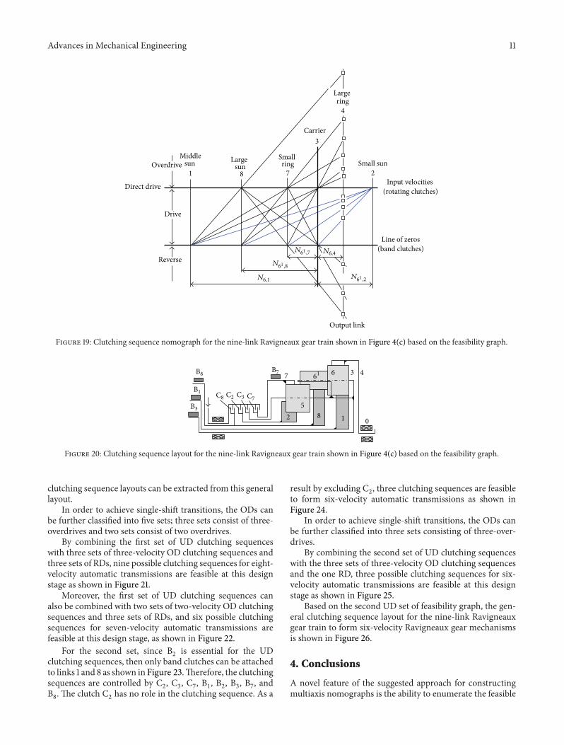
Figure 18 reveals that a clutch cannot be attached to link1; thus, the last three reverse clutching sequences shownin Figure 17(a) are inadmissible. As a result, only thirteenclutching sequences shown in Figure 19 are feasible at thisdesign stage.
Based on the first UD set of feasibility graph, the generalclutching sequence layout for the nine-link Ravigneaux geartrain is shown in Figure 20. All of the eight-velocity feasible
Advances in Mechanical Engineering 11
Middle Large Small
Carrier
Large
Small sun
Output link
71 2
3
8
4
sun sun ring
ring
𝑁61 ,7
𝑁61 ,8
𝑁61 ,2
𝑁6,4
𝑁6,1
Overdrive
Direct drive
Drive
Input velocities(rotating clutches)
Line of zeros(band clutches)
Reverse
Figure 19: Clutching sequence nomograph for the nine-link Ravigneaux gear train shown in Figure 4(c) based on the feasibility graph.
012 8
3 4
5
67 61
B1
B8 B7
B3
C2C8 C3 C7
Figure 20: Clutching sequence layout for the nine-link Ravigneaux gear train shown in Figure 4(c) based on the feasibility graph.
clutching sequence layouts can be extracted from this generallayout.
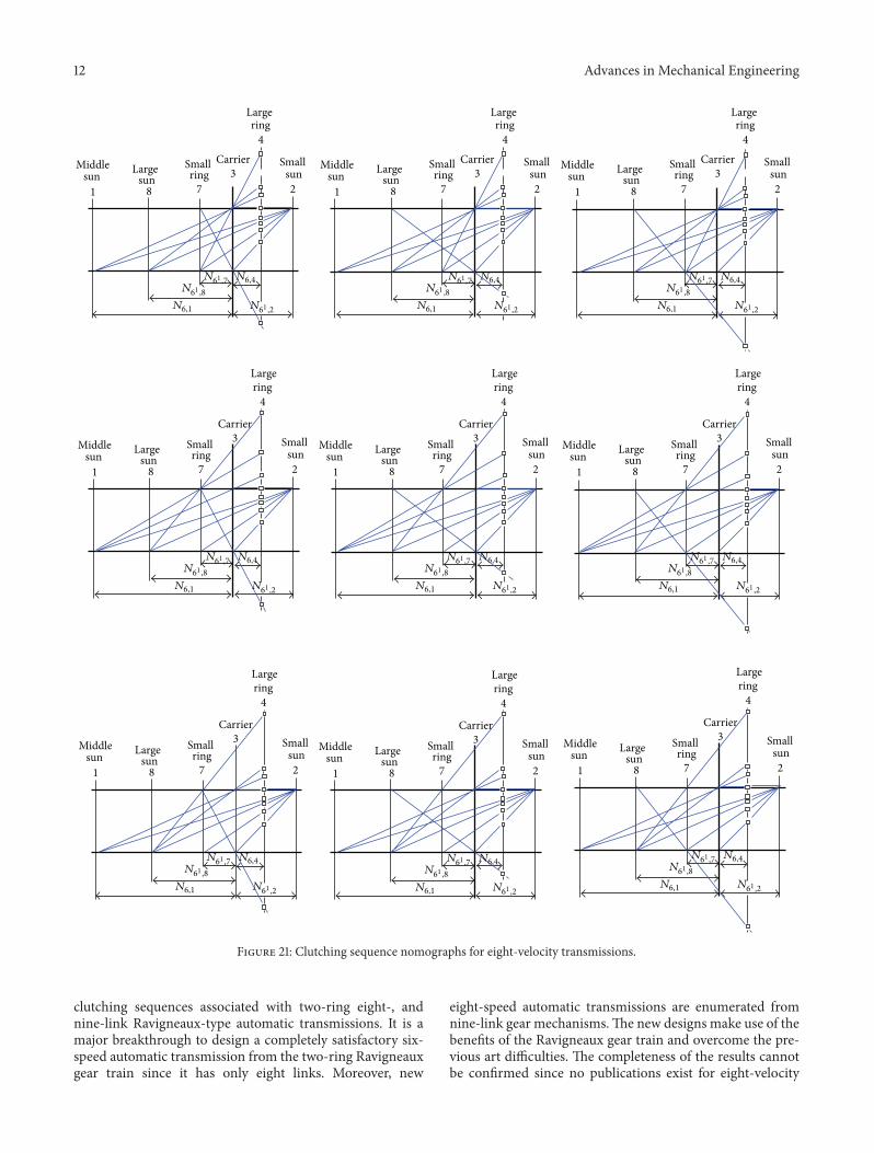
In order to achieve single-shift transitions, the ODs canbe further classified into five sets; three sets consist of three-overdrives and two sets consist of two overdrives.
By combining the first set of UD clutching sequenceswith three sets of three-velocity OD clutching sequences andthree sets of RDs, nine possible clutching sequences for eight-velocity automatic transmissions are feasible at this designstage as shown in Figure 21.
Moreover, the first set of UD clutching sequences canalso be combined with two sets of two-velocity OD clutchingsequences and three sets of RDs, and six possible clutchingsequences for seven-velocity automatic transmissions arefeasible at this design stage, as shown in Figure 22.
For the second set, since B2is essential for the UD
clutching sequences, then only band clutches can be attachedto links 1 and 8 as shown in Figure 23.Therefore, the clutchingsequences are controlled by C
2, C3, C7, B1, B2, B3, B7, and
B8. The clutch C
2has no role in the clutching sequence. As a
result by excluding C2, three clutching sequences are feasible
to form six-velocity automatic transmissions as shown inFigure 24.
In order to achieve single-shift transitions, the ODs canbe further classified into three sets consisting of three-over-drives.
By combining the second set of UD clutching sequenceswith the three sets of three-velocity OD clutching sequencesand the one RD, three possible clutching sequences for six-velocity automatic transmissions are feasible at this designstage as shown in Figure 25.
Based on the second UD set of feasibility graph, the gen-eral clutching sequence layout for the nine-link Ravigneauxgear train to form six-velocity Ravigneaux gear mechanismsis shown in Figure 26.
4. Conclusions
A novel feature of the suggested approach for constructingmultiaxis nomographs is the ability to enumerate the feasible
12 Advances in Mechanical Engineering
Middle Large Small Carrier
Large
Small
71 23
8
4
sun sun ring
ring
𝑁61,8
𝑁61,7
𝑁61,2
𝑁6,4
𝑁6,1
sunMiddle Large Small Carrier
Large
Small
71 23
8
4
sun sun ring
ring
𝑁61,8
𝑁61,7
𝑁61,2
𝑁6,4
𝑁6,1
sunMiddle Large Small Carrier
Large
Small
71 23
8
4
sun sun ring
ring
𝑁61,8
𝑁61,7
𝑁61,2
𝑁6,4
𝑁6,1
sun
Middle Large Small
Carrier
Large
Small
71 2
3
8
4
sun sun ring
ring
𝑁61,8
𝑁61,7
𝑁61,2
𝑁6,4
𝑁6,1
sunMiddle Large Small
Carrier
Large
Small
71 2
3
8
4
sun sun ring
ring
𝑁61,8
𝑁61,7
𝑁61,2
𝑁6,4
𝑁6,1
sunMiddle Large Small
Carrier
Large
Small
71 2
3
8
4
sun sun ring
ring
𝑁61,8
𝑁61,7
𝑁61,2
𝑁6,4
𝑁6,1
sun
Middle Large Small
Carrier
Large
Small
71 2
3
8
4
sun sun ring
ring
𝑁61,8
𝑁61,7
𝑁61,2
𝑁6,4
𝑁6,1
sunMiddle Large Small
Carrier
Large
Small
71 2
3
8
4
sun sun ring
ring
𝑁61,8
𝑁61,7
𝑁61,2
𝑁6,4
𝑁6,1
sunMiddle Large Small
Carrier
Large
Small
71 2
3
8
4
sun sun ring
ring
𝑁61,8
𝑁61,7
𝑁61,2
𝑁6,4
𝑁6,1
sun
Figure 21: Clutching sequence nomographs for eight-velocity transmissions.
clutching sequences associated with two-ring eight-, andnine-link Ravigneaux-type automatic transmissions. It is amajor breakthrough to design a completely satisfactory six-speed automatic transmission from the two-ring Ravigneauxgear train since it has only eight links. Moreover, new
eight-speed automatic transmissions are enumerated fromnine-link gear mechanisms.The new designs make use of thebenefits of the Ravigneaux gear train and overcome the pre-vious art difficulties. The completeness of the results cannotbe confirmed since no publications exist for eight-velocity

Advances in Mechanical Engineering 13
Middle Large Small Carrier
Large
Small
71 2
38
4
sun sun ring
ring
𝑁61 ,8
𝑁61,7
𝑁61 ,2
𝑁6,4
𝑁6,1
sunMiddle Large Small
Carrier
Large
Small
71 23
8
4
sun sun ring
ring
𝑁61 ,8
𝑁61 ,7
𝑁61 ,2
𝑁6,4
𝑁6,1
sunMiddle Large Small Carrier
Large
Small
71 2
3
8
4
sun sun ring
ring
𝑁61 ,8
𝑁61 ,7
𝑁61 ,2
𝑁6,4
𝑁6,1
sun
Middle Large Small
Carrier
Large
Small
71 2
3
8
4
sun sun ring
ring
𝑁61 ,8
𝑁61 ,7
𝑁61 ,2
𝑁6,4
𝑁6,1
sunMiddle Large Small
Carrier
Large
Small
71 2
3
8
4
sun sun ring
ring
𝑁61 ,8
𝑁61 ,7
𝑁61 ,2
𝑁6,4
𝑁6,1
sunMiddle Large Small
Carrier
Large
Small
71 2
3
8
4
sun sun ring
ring
𝑁61 ,8
𝑁61 ,7
𝑁61 ,2
𝑁6,4
𝑁6,1
sun
Figure 22: Clutching sequence nomographs for seven-velocity transmissions.
C7
C3
C2C8C1
B7 B3
B8B2 B1
1
8
23
47 O
Figure 23: Feasibility graphs for the Ravigneaux gear train.
Ravigneaux gear mechanisms. The proposed methodologycan be used for the systematic design of any epicyclic-typeautomatic transmission. Feasibility graphs have been also
Middle Large
OverdriveSmall
Carrier
Large
Small
Direct
Drive
Input velocities(rotating clutches)
Line of zeros(band clutches)
Reverse
Output link
71 2
3
8
4
sun sun ring
ring
sun
drive
𝑁61 ,8
𝑁61 ,7
𝑁61 ,2
𝑁6,4
𝑁6,1
Figure 24: Clutching sequence nomograph for the nine-link Ravi-gneaux gear train based on the second UD set feasibility graph.
used as a design tool, allowing the designer to quickly selectthe most viable clutching sequence.

14 Advances in Mechanical Engineering
Middle Large Small Carrier Small
71 238sun sun ring
Large
4ring
sun
𝑁61 ,8
𝑁61 ,7
𝑁61 ,2
𝑁6,4
𝑁6,1
Middle Large Small
Carrier
Small
71 2
3
8sun sun ring
Large
4ring
sun
𝑁61 ,8
𝑁61 ,7
𝑁61 ,2
𝑁6,4
𝑁6,1
Middle Large Small
Carrier
Small
71 2
3
8sun sun ring
Large
4ring
sun
𝑁61 ,8
𝑁61 ,7
𝑁61 ,2
𝑁6,4
𝑁6,1
Output link Output link Output link
Figure 25: The three feasible clutching sequences for six-velocity automatic transmissions.
B3
B1
B8
B2B7
C7C3
125
8
3 467
0
61
Figure 26: Clutching sequence layout for the nine-link Ravigneauxgear train based on the second UDs, ODs and RDs.
References
[1] P. Ravigneaux, “Gear box with freewheeling gear,” US patent no.2195783, 1940.
[2] P. Ravigneaux, “Speed changing device,” US patent no. 2220174,1940.
[3] L. W. Tsai,Mechanism Design: Enumeration of Kinematic Struc-tures According to Function, CRC Press, Boca Raton, Fla, USA,2001.
[4] E. Wilfinger and J. Thompson, Borg-Warner Australia Model85 Automatic Transmission, SAE Paper no. 880480, Society ofAutomotive Engineers, 1988.
[5] C. H. Hsu and R. H. Huang, “Systematic design of four-speedravigneaux-type automatic transmissions,” Journal of ChineseSociety ofMechanical Engineers, vol. 30, no. 3, pp. 201–209, 2009.
[6] H. Naunheimer, B. Bertsche, J. Ryborz, andW. Novak, “Vehicletransmission systems: basic design principles,” in AutomotiveTransmissions: Fundamentals, Selection, Design and Application,Springer, Berlin, Germany, 2nd edition, 2011.
[7] N. Katou, T. Taniguchi, and K. Tsukamoto, Aisin AW New Six-Speed Automatic Transmission for FWDVehicles, SAE Paper no.2004-01-0651, 2004.
[8] P. A. G. Lepelletier, “Multispeed automatic transmission forautomobile vehicles,” US patent no. 5106352, 1992.
[9] H. Scherer, ZF 6-Speed Automatic Transmission for PassengerCars, SAE Paper no. 2003-01-0596, Society of AutomotiveEngineers, 2003.
[10] P. Ravigneaux, “Epicyclic change-speed gear,” US patent no.2761333, 1956.
[11] B. A. Nadel and J. Lin, “Automobile transmission design as aconstraint satisfaction problem: first results,” in Proceedings ofthe 7th IEEE Conference on Artificial Intelligence Applications,vol. 1, pp. 248–256, February 1991.
[12] B. A. Nadel and J. Lin, “Automobile transmission design asa constraint satisfaction problem: modeling the kinematiclevel,” Artificial Intelligence for Engineering Design, Analysis andManufacturing, vol. 5, no. 3, pp. 137–171, 1991.
[13] B. A. Nadel, X. Wu, and D. Kagan, “Multiple abstractionlevels in automobile transmission design: constraint satisfactionformulations and implementations,” International Journal ofExpert Systems, vol. 6, no. 4, pp. 489–559, 1993.
[14] H. I. Hsieh and L. W. Tsai, “A methodology for enumerationof clutching sequences associated with epicyclic-type automatictransmissionmechanisms,” SAETransactions, vol. 105, no. 6, pp.928–936, 1996.
[15] H. I. Hsieh and L. W. Tsai, “The selection of a most efficientclutching sequence associated with automatic transmissionmechanisms,” Journal of Mechanical Design, vol. 120, no. 4, pp.514–519, 1998.
[16] W. M. Hwang and Y. L. Huang, “Configuration design ofsix-speed automatic transmissionswith two-degree-of-freedomplanetary gear trains,” Transactions of the Canadian Society forMechanical Engineering, vol. 29, no. 1, pp. 41–55, 2005.
[17] C. H. Hsu and R. H. Huang, “Systematic design of six-speed automatic transmissions with an eight-link two-DOFRavigneaux gearmechanism,” Journal ofMechanical Design, vol.131, no. 1, Article ID 011004, 8 pages, 2009.
[18] C. S. Ross and W. D. Route, “A method for selecting parallel-connected, planetary gear train arrangements for automotiveautomatic transmissions,” SAE Transactions, vol. 100, no. 6, pp.1765–1774, 1991.
[19] E. L. Esmail, “Nomographs for enumeration of clutchingsequences associated with epicyclic type automatic transmis-sion mechanisms,” in Proceedings of the ASME InternationalMechanical Engineering Congress and Exposition (IMECE ’08),Boston,Mass, USA, October-November 2008, paper no. 66409,also at Emirates Journal for Engineering Research, vol. 14, no.1,pp. 29–38, 2009.

Advances in Mechanical Engineering 15
[20] N. Hattori, T. Oshidari, and Y.Morimono, “Application of a newcomplex planetary gear set to five-speed automatic transmissiongear train,” Transactions of the Society of Automotive Engineersof Japan, vol. 26, no. 1, pp. 79–82, 1995.
[21] G. Chatterjee and L. W. Tsai, “Enumeration of epicyclic-typetransmission gear trains,” Transactions of SAE, vol. 103, no. 6,pp. 1415–1426, 1995, paper no. 941012.
[22] H. I. Hsieh and L.W. Tsai, “Kinematic analysis of epicyclic-typetransmission mechanisms using the concept of fundamentalgeared entities,” Journal of Mechanical Design, vol. 118, no. 2, pp.294–299, 1996.
[23] H. I. Hsieh, Enumeration and selection of clutching sequencesassociated with epicyclic-type transmission mechanisms [Ph.D.thesis], Department of Mechanical Engineering, University ofMaryland, College Park, Md, USA, 1996.
[24] W. M. Hwang and Y. L. Huang, “Connecting clutch elementsto planetary gear trains for automotive automatic transmissionsvia coded sketches,” Mechanism and Machine Theory, vol. 46,no. 1, pp. 44–52, 2011.
[25] E. L. Esmail, “Kinematic nomographs of epicyclic-typetransmission mechanisms,” Emirates Journal for EngineeringResearch, vol. 12, no. 3, pp. 47–55, 2007.
[26] E. L. Esmail, “Nomographs for analysis of power circulationthrough closed epicyclic gear trains,” Emirates Journal ForEngineering Research, vol. 16, no. 2, pp. 1–9, 2011.
[27] E. L. Esmail and H. A. Hussen, “Nomographs for kinematics,statics and power flow analysis of epicyclic gear trains,” inProceedings of the ASME International Mechanical EngineeringCongress and Exposition (IMECE ’09), vol. 13, pp. 631–640, LakeBuena Vista, Fla, USA, November 2009, paper no. 10789.
[28] E. L. Esmail, “Teaching planetary gear trains with the aid ofnomographs,” Advances in Mechanical Engineering, vol. 2013,Article ID 978418, 9 pages, 2013.

Submit your manuscripts athttp://www.hindawi.com
Control Scienceand Engineering
Journal of
Hindawi Publishing Corporationhttp://www.hindawi.com Volume 2013
International Journal of
RotatingMachinery
Hindawi Publishing Corporationhttp://www.hindawi.com
Volume 2013Part I
Hindawi Publishing Corporationhttp://www.hindawi.com Volume 2013
DistributedSensor Networks
International Journal of
ISRN Signal Processing
Hindawi Publishing Corporationhttp://www.hindawi.com Volume 2013
Hindawi Publishing Corporationhttp://www.hindawi.com Volume 2013
Mechanical Engineering
Advances in
Modelling & Simulation in EngineeringHindawi Publishing Corporationhttp://www.hindawi.com Volume 2013
Advances inOptoElectronics
Hindawi Publishing Corporationhttp://www.hindawi.com
Volume 2013
ISRN Sensor Networks
Hindawi Publishing Corporationhttp://www.hindawi.com Volume 2013
VLSI Design
Hindawi Publishing Corporationhttp://www.hindawi.com Volume 2013
Hindawi Publishing Corporation http://www.hindawi.com Volume 2013Hindawi Publishing Corporation http://www.hindawi.com Volume 2013
The Scientific World Journal
ISRN Robotics
Hindawi Publishing Corporationhttp://www.hindawi.com Volume 2013
International Journal of
Antennas andPropagation
Hindawi Publishing Corporationhttp://www.hindawi.com Volume 2013
ISRN Electronics
Hindawi Publishing Corporationhttp://www.hindawi.com Volume 2013
Hindawi Publishing Corporationhttp://www.hindawi.com Volume 2013
Journal of
Sensors
Hindawi Publishing Corporationhttp://www.hindawi.com Volume 2013
Active and Passive Electronic Components
Chemical EngineeringInternational Journal of
Hindawi Publishing Corporationhttp://www.hindawi.com Volume 2013
Hindawi Publishing Corporationhttp://www.hindawi.com Volume 2013
Electrical and Computer Engineering
Journal of
ISRN Civil Engineering
Hindawi Publishing Corporationhttp://www.hindawi.com Volume 2013
Advances inAcoustics &Vibration
Hindawi Publishing Corporationhttp://www.hindawi.com Volume 2013