nominal planning of a lte700 ppdr network in germany · 2020-01-28 · nominal planning of a lte700...
TRANSCRIPT
Nominal Planning of a LTE700 Network for PPDR Page 1
Technical Report / Teaching Material
Nominal Planning of a LTE700 PPDR Network in Germany
Prof. Dr. Andreas Timm-Giel, {[email protected]}
Institute of Communication Networks, Hamburg University of Technology
Version 1.0, September 19th, 2019,
DOI: https://doi.org/10.15480/882.2408
1. Abstract
In Germany, 2 x 8MHz spectrum was assigned to Public Protection and Disaster Release (PPDR)
services in the 700MHz frequency band. Currently public authorities operate for blue light services a
national TETRA network using approximately 4,700 base station sites. This technical report examines
the site portfolio for a national PPDR LTE network in 700MHz based on planning parameter for a
PPDR network in Spain as published in [1]. Furthermore, the resulting planning margins are analysed
using a common methodology for the nominal site count planning. Both planning approaches show
that the number of sites given by TETRA is sufficient for a high quality LTE-based PPDR network in
Germany.
The following chapter shows the assumptions taken for the network planning. In chapter 3, the
planning approach in Spain is summarized and applied for the site layout in Germany. In chapter 4, a
common method for the nominal planning is used. However, in this case this method was applied not
for obtaining the number of required sites, but for calculating the power budget margins if using the
existing number of sites. Chapter 5 summarises this technical study.
2. Planning assumptions
Following planning assumptions are used for this technical study.
a) Site layout
Existing TETRA sites for blue light services will be equipped with LTE technology (eNodeB)
and 700MHz antennas. LTE with the distributed eNodeB design allows the installation of
radio heads (remote radio units) close to the antenna. Such a design reduces the feeder
cable loss, anyway being relatively small in the 700MHz frequency band, even further.
b) Services
The study [1] assumes a network, which is capable to deliver HD videos in the Uplink even
from the coverage edge. In this study a typical LTE planning criterion of 64 kbit/s at the cell
edge as used in [2] and [5] is considered. This is assumed to be sufficient for the planned
PPDR services in Germany, i.e. messaging and data base access. Due to overlapping cell and
planning margins the obtainable data rates in networks designed to this criterion are
typically much higher.
c) LTE technology and antennas
Nominal Planning of a LTE700 Network for PPDR Page 2
The LTE air interface is designed for broadband services. SC-FDMA Single Carrier Frequency
Division Multiple Access in uplink (pre-coded OFDMA with dynamic bandwidth) and adaptive
OFDMA Orthogonal Frequency Division Multiple Access in downlink lead to high spectral
efficiency. Furthermore, MIMO schemes and carrier aggregation (CA) contribute to high data
throughputs. Therefore, the use of MIMO antennas in the initial network design is assumed
for future-proof networks. A 4x4 MIMO base station antenna (e.g. Kathrein 4-Port Xpol
80010902) with 16dBi gain is assumed for the LTE700 network planning. The CA-feature of
700MHz band with other frequency bands is not considered in this study. For the LTE base
station receiver a noise figure of 2dB is assumed, same as in [2].
d) Devices
3GPP has defined a high power class for devices especially for the extension of coverage of
PPDR networks. The power class 1 with 31dBm transmission power is defined in 700 MHz
bands. For the future-proof network design this power class is used in this study. However,
this study considers also a use of commercial devices by blue light officers with power class 3
which are limited to 23dBm transmission power. Possible antenna gains for user devices are
not considered here.
3. PPDR planning approach
3.1 Interpretation of the planning approach in [1]
The planning approach used in [1] is based on an outdoor planning with high planning margins. One
planning margin in this approach is connected to a very high modulation scheme of 16QAM being the
highest mandatory modulation scheme in the uplink. Another margin results from the assumption of
using all available resource blocks (25 in 5MHz channel) at the cell edge. Further, an HD video
transmissions in the uplink with a resolution of 1920 x 1080 pixels is assumed also at the cell edge.
This results in the minimum requirement for the Signal-to-Interference and Noise Ratio (SINR) at the
cell edge of 5dB and an eNodeB sensitivity of -100dBm.
In real network large cell overlapping exists for continuous radio coverage leading to a low
probability of locations with cell edge properties. Furthermore, the assignment of all available
resource blocks to one user only at the cell edge is very unlikely. In such a case all other active users
in the cell are not served. With the assignment of a lower number of resource blocks the actual
achievable SINR value increases due to the lower noise power, thus higher modulation and coding
schemes providing higher bit rates per resource block are possible in principle. This adaptive
mechanism, of course, only works up to the defined highest modulation and coding scheme.
Therefore, the assumed SINR (for 16QAM) and the use of all resource blocks can be both interpreted
as planning margins.
The LTE planning approach in [2] and in [5] assumes the use of two resource blocks at the cell edge.
Furthermore, an SINR value of -7dB for 64kbit/s is assumed in this approach. Compared to the
approach used in [1] the margin for SINR is 12dB (5dB - (-7dB)) and a further margin in sensitivity
arise due to use of two blocks instead of 25, i.e. 10xlog(25/2) = 11dB. In summary, different cell edge
properties use in [1] and in [2] and [5] lead to the total margin of 23 dB.

Nominal Planning of a LTE700 Network for PPDR Page 3
For the LogNorm fading with a standard deviation of 6dB a cell edge availably of 90% (95% cell area
availability) shall be ensured by the definition of the planning level. This requirement leads to a
planning margin of 7.7dB.
The authors of [2] interpret planning margins for high area location probability as a contribution to
the indoor coverage.
This means, that margins for high location probability derived from the standard deviation of
LogNorm fading also help the indoor penetration. In accordance to [2] the area location probability
of 95% as assumed in [1] is experienced by the user as a “fair indoor” coverage. Following this
interpretation of planning margins a further margin of 23dB due to different cell edge properties as
derived above will finally change the subjective coverage experience from the “fair indoor” to at least
“excellent indoor”.
Another small margin is connected to the assumed base station antenna with 15dBi in the study [1].
For the future prove network design the use of state of the art antennas with 16dBi can be assumed.
Other planning parameters like 2dB noise figure of the base station receiver and the use of high
power devices with 31dBm Effective Isotropic Radiated Power (EIRP) are in line with assumptions
listed in Chap. 2.
3.2 Application of PPDR planning approach [1] to Germany
In the following analysis ,the approach as used in [1] is applied for the planning of a PPDR LTE700
network in Germany. The only difference to the assumption [1] is the change of antenna gain from
15dBi to 16dBi which is motivated by the use of state of the art antenna (e.g. Kathrein 80010902). All
other margins mentioned above are not applied for the following site count planning. Therefore, the
value of the maximum allowable path loss changes by 1dB from 136.3 to 137.3 dB. The value of the
maximum allowable path loss is responsible for the cell range and consequently for the number of
required sites.
The value of the maximum allowable path loss can be used for the calculation of the cell range using
a model for the propagation loss (i.e. modified Hata model) in different environments [3]. The
classification of Germany in different morphology classes used by modified Hata-Model can be found
for example in [7].
The number of required sites in Germany is calculated in the following Table 1.

Nominal Planning of a LTE700 Network for PPDR Page 4
Unit Comments
Frequency MHz 700 700 700
Morphology Urban Suburban Open
Max. allowable path loss
dB 137.3 137.3 137.3 from [1] +1dB for higher antenna gain
BS antenna height m 30.0 35.0 35.0 Typical BS heights, see 3GPP
Cell range km 2.43 4.84 16.10 Calculated with mod. Hata model
Cell area km² 15.3 60.8 673.8 Hexagon
Morphology classes % 5% 28% 66%
Morphology classes km² 18,000 102,000 238,000 German area 358k km²
Number of sites 1,175 1,679 354
Percentile of sites per morphology class
36.6% 52.3% 11.0%
Resulting number of LTE700 sites
3,208
Table 1: Resulting site count based on the planning approach for PPDR in [1]
In result, the application of the planning approach from for PPDR Network in Spain [1] with a small
correction of 1dB for the antenna gain leads to approximately 3.200 sites required for a nationwide
LTE700 network in Germany. This is much lower number than the existing 4,700 PPDR site from
TETRA. This planning does not consider margins for the chosen [1] cell edge properties. With these
power margins of 23 dB the subjective coverage can be assumed as excellent indoor.
A further consideration based on this approach is the calculations of the additional coverage margin
assuming the implementation of LTE700 at all available PPDR sites. In the following Table 2 it is
shown that the maximal allowable path loss of uniformly 134.4dB for all morphology classes leads to
app. 4,700 sites. That means the planning based on [1] contains app. 3dB additional margin if the
LTE700 network would be implemented on all available sites.
Unit Comment
Frequency 700 700 700
Morphology Urban Suburban Open
Max. allowable path loss
dB 134.4 134.4 134.4 Calculated max. path loss for app. 4,700 Sites
BS Antenna height m 30.0 35.0 35.0 Typical BS heights, see 3GPP
Cell range km 2.01 3.99 13.29 Calculated with mod. Hata model
Cell area km² 10.5 41.4 459.0 Hexagon
Morphology classes % 5% 28% 66%
Morphology classes km² 18,000 102,000 238,000 German area 358k km²
Number of sites 1,716 2,464 519
Percentile of sites per morphology class
% 36.5% 52.4% 11.0%
Resulting number of LTE700 sites
4,699
Table 2: Maximum allowable path loss for 4,700 sites
Nominal Planning of a LTE700 Network for PPDR Page 5
Together with the calculated margins for cell edge properties the total planning margin is about 26dB
in case of using 4,700 sites in Germany.
4. Calculation of planning margins
A different way for the evaluation the available site portfolio for LTE700 network is the application of
a common nominal site count methodology for the calculations of planning margins. These planning
margins can be later used for taking into account other losses like building penetration losses, body
losses if using handheld devices or lower power devices (e.g. power class 3 devices with 23dBm
transmission power). Similarly to the approach in the chap. 3 only uplink is considered which is
typically weaker than the DL for the calculation of maximum allowable path loss.
The SINR requirement of -7dB at the cell edge is taken from [2] or [5]. Furthermore, the use of two
resource blocks is assumed which is sufficient together with the SINR requirement for 64kbit/s at the
cell edge in accordance to [2] and [5].
Further assumptions in line with Chap. 2 are: gain of the base station antenna 16dBi, feeder losses
1dB, noise figure of BS receiver 2dB, interference margin in the uplink 1dB, handover gain 2.5dB [4]
and different standard deviations LogNorm for LogNorm fading for urban 8dB, suburban and rural
areas 6dB.
For other losses a standard deviation other of uniform 6dB is chosen. Both slow fading and standard
deviation of other losses contribute to the planning margin for higher availability than 50% at the cell
edge. With the assumption of two independent statistic processes the resulting standard deviation is:
𝜎𝑡𝑜𝑡𝑎𝑙 = √𝜎𝐿𝑜𝑔𝑁𝑜𝑟𝑚2 + 𝜎𝑜𝑡ℎ𝑒𝑟
2 . (1)
The resulting margin necessary for 95% location availability i.e. 1.28 x total (12.8dB for urban, 10.9dB
for suburban and rural) is taken into account for the nominal planning (see Table 3). For the
application of the common nominal site count planning method it is assumed that other losses in
urban areas are 2dB higher than in suburban and 2 dB lower in rural than in suburban areas. In the
following table the average resulting losses are determined in the way that the resulting number of
sites is 4,700 (as shown in the Table 4).

Nominal Planning of a LTE700 Network for PPDR Page 6
Unit LTE700
Comments UL UL UL
Urban Suburban Open
Device EIRP dBm 31 31 31 3GPP, high Power UE with 0 dBi Antenna
Antenna gain dBi 16 16 16 Kathrein 80010902
Cable losses dB 1 1 1 Short feeder cable
NF dB 2 2 2 State of the art BS receiver
SINR dB -7 -7 -7 [2], [5] 64kbit/s at the cell edge
#RB 2 2 2 [2], [5]
Sensitivity dBm -123.4 -123.4 -123.4 Calculated from SINR und NF and white noise power
Standard deviation of slow fading
dB 8 6 6 assumption
Standard deviation of other losses
dB 6 6 6 assumption
Aggregated standard deviation
dB 10.0 8.5 8.5 See equation (1)
Location availability at the cell edge
% 90 90 90 95% location availability
Margin for slow fading and other losses variances
dB 12.8 10.9 10.9 Aggregated margin
Interference margin dB 1.0 1.0 1.0 see [2]
Handover Gain dB 2.5 2.5 2.5 see [4]
Resulting other losses dB 26.14 24.14 22.14 Resulting losses for building penetration, body loss and lower terminal powers
Max. allowable path loss dB 132.0 135.9 137.9
Table 3: Calculation of the resulting other losses for the nominal planning with approximately
4,700 sites
The resulting other losses differ among environments because of the different assumptions regarding
the standard deviation of LogNorm fading and assumed differences in average losses in different
environments. The resulting nominal planning of approximately 4,700 sites with the calculated other
losses is proven in Table 4. This table shows that the coverage is given with the service location
availability of 95% with the following other losses 26dB for urban, 24dB for suburban and 22dB for
rural.

Nominal Planning of a LTE700 Network for PPDR Page 7
LTE700 Unit
Morphology Urban Suburban Open
Max. allowable path loss dB 132.0 135.9 137.9
BS antenna height m 30.0 35.0 35.0
Cell range km 1.72 4.41 16.78
Cell area km² 7.6 50.6 731.7
Morphology classes in % % 5% 28% 66%
Morphology classes in km² km² 18,000 102,000 238,000
Number of sites 2,354 2,015 326
Resulting number of sites for the LTE700 network
4,695
Table 4: Resulting number of sites for the maximum path loss based on other losses taken
from Table 3.
The resulting other losses can be used for taking into account various effects like building
penetration, body loss etc. The variance of these effects is already considered while calculating the
service location availability.
Since the measured building entry loss in 700MHz band in Germany is in average 8.5dB [6] and there
are lots of margins left for other losses, lower devices transmission power or higher service location
availability. After the subtraction of the average building entry loss there is still additional 17.64dB
left for other losses in urban areas. For suburban and rural areas this value is 15.64dB respectively
13.64dB.
If considering low power devices with 23dBm transmission power (i.e. power class 3) and no
additional antenna gains instead of PPDR devices with 31dBm EIRP the margins will be 8dB lower.
But also in this case margins for other losses or higher availability remain positive (9.64dB in urban,
7.64dB in suburban und 5.64dB in rural areas).
Another possibility of coverage surplus use is a growth of the location availability. If increasing the
cell edge location availability from 90% to 95% the area location availability increases from 95% to
99% assuming the propagation exponent of 3.5. This high location availability can be achieved with
an additional margin of app. 1.4dB which is shown in the Annex. However, it should be mentioned
that PPDR users besides the higher availability will experience higher bitrates if adding margins for
increased availability due to technology inherent adaptive adjustments of modulation and coding
schemes.
In both cases e.g. for lower device power or for higher availability or even taking into account both
cases there are still remaining margins left for consideration of other losses. This margins if not
consumed extreme penetration losses like deep indoor usage will always be used by the LTE system
for the provision of higher throughputs and thus for better user experience.
5. Summary
This technical report studies two approaches for LTE700 network planning for PPDR application in
Germany using the existing 4,700 sites. The first one transfers PPDR planning approach for a very
demanding service e.g. HD video links in uplink published in [1] to German antenna site grid.

Nominal Planning of a LTE700 Network for PPDR Page 8
The second approach is a nominal site count planning which is commonly used in order to estimate
the number of required antenna sites for an assumed service. Since the number of sites is known this
approach was used here for the calculation of potential other losses. Different assumptions have
been made for other losses in urban, suburban and rural areas in order to take into account
differences in building penetration in various areas. The calculated other losses can be further used
for consideration of various use cases: building penetration, body losses, lower transmission power
of devices or higher service location availability.
Both approaches show that LTE700 network for PPDR use built on 4,700 sites provides highly
available in building coverage with high bitrates. Furthermore, both approaches provide some
additional margins, which can be used for better user experience.
Acknowledgement:
This technical report is based on discussions with Andrzej Cwik, who gave valuable input for the
report.
Nominal Planning of a LTE700 Network for PPDR Page 9
Annex
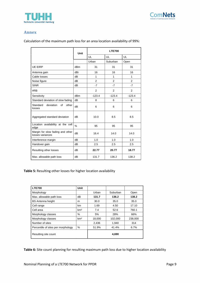
Calculation of the maximum path loss for an area location availability of 99%:
Unit
LTE700
UL UL UL
Urban Suburban Open
UE EIRP dBm 31 31 31
Antenna gain dBi 16 16 16
Cable losses dB 1 1 1
Noise figure dB 2 2 2
SINR dB -7 -7 -7
#RB 2 2 2
Sensitivity dBm -123.4 -123.4 -123.4
Standard deviation of slow fading dB 8 6 6
Standard deviation of other losses
dB 6 6 6
Aggregated standard deviation dB 10.0 8.5 8.5
Location availability at the cell edge
% 95 95 95
Margin for slow fading and other losses variances
dB 16.4 14.0 14.0
Interference margin dB 1.0 1.0 1.0
Handover gain dB 2.5 2.5 2.5
Resulting other losses dB 22.77 20.77 18.77
Max. allowable path loss dB 131.7 136.2 138.2
Table 5: Resulting other losses for higher location availability
LTE700 Unit
Morphology Urban Suburban Open
Max. allowable path loss dB 131.7 136.2 138.2
BS Antenna height m 30.0 35.0 35.0
Cell range km 1.69 4.50 17.10
Cell area km² 7.4 52.6 760.1
Morphology classes % 5% 28% 66%
Morphology classes km² 18,000 102,000 238,000
Number of sites
2,436 1,940 314
Percentile of sites per morphology % 51.9% 41.4% 6.7%
Resulting site count
4,690
Table 6: Site count planning for resulting maximum path loss due to higher location availability
Nominal Planning of a LTE700 Network for PPDR Page 10
6. References
[1] Diego del Rey Carrión 1, Leandro Juan-Llácer 2 and José-Víctor Rodríguez, Radio Planning
Considerations in TETRA to LTE Migration for PPDR Systems: Radioelectric Coverage Case
Study, applied sciences, MDPI, 11 January 2019
[2] Jyrki T. J. Penttinen, Giesecke & Devrient (editor), The LTE Advanced Deployment Handbook,
Wiley 2016
[3] ERC Report 68, Monte-Carlo Simulation Methodology for the Use in Sharing and Compatibility
Studies between different Radio Services or Systems, June 2002
[4] Chris Johnson, Long Term Evolution in Bullets, Wiley 2012
[5] Harri Homa, Antti Toskala (editor), LTE for UMTS: Evolution to LTE Advanced, Wiley 2011
[6] Report ITU-R P.2346-0, Compilation of measurement data relating to building entry loss,
(05/2015)
[7] Digitalisierung der Energiewende, EY, BET, WIK,
https://www.bmwi.de/Redaktion/DE/Publikationen/Studien/digitalisierung-der-energiewende.html