noaa technical report nos ngs 51
TRANSCRIPT

1
NOAA Technical Report NOS NGS 51 Final Report
2013–2014 Survey of the Washington Monument
Washington, D.C.
February 16, 2015

2
Cover photograph:
Image taken through the lens of the TDM 5000 total station, sighting the reflector mounted
at the peak of the Washington Monument. Access to peak was made possible by the renovation
scaffolding surrounding the monument. National Geodetic Survey (NGS) employees are
mounting a reflector over the peak. (Photograph edited to remove reticules of the TDM 5000
instrument.)

3
4
Executive Summary
A rare 5.8-magnitude earthquake struck the Piedmont region of Virginia on August 23, 2011,
shaking the Nation’s capital with sufficient force to crack stones and loosen mortar in the
Washington Monument (WM). Scaffolding built around the structure to facilitate repairs made to
the building in 2013 and 2014 provided a rare opportunity for NOAA’s National Geodetic
Survey (NGS) to perform a geodetic survey incorporating direct occupation of the WM peak
with multiple instruments.
Although NGS—formerly the U.S. Coast and Geodetic Survey (USC&GS)—surveyed points at
the base of the WM many times in the building’s 120-plus year history, only twice before (in
1934 and 1999) had full scaffolding allowed surveyors access to the peak of the structure. The
1934 and 1999 surveys were of insufficient accuracy to detect whether any subtle changes had
taken place in the peak’s three-dimensional location in space.
The new scaffolding provided NGS the opportunity to once again collaborate with the National
Park Service (NPS) to survey the peak of the WM, this time with greater accuracy than
previously achieved. NGS’ primary goal for the new endeavor was to position the peak within
the National Spatial Reference System (NSRS), and as a secondary goal, to provide a building
height measured to an international standard.
In 1885, Lt. Col. Thomas Lincoln Casey reported the height of the WM as “555 feet,
5 1/8 inches.” Modern attempts to validate the 1885 measurement have been difficult, because
the “architectural zero height point” (AZHP) location—the actual starting point for that
measurement—is currently unknown.
For the first time in modern history (1999), NGS attempted to validate the 1885 height by using
GPS technology and by hypothesizing the location of the 1885 AZHP. The result of that height
measurement, 555 feet, 3 5/8 inches, was close enough to substantiate the hypothesis made about
the 1885 AZHP location. However, while the 1999 measurement was in agreement with the 1885
height within 1 ½ inches, it did not reflect the international standard for the measurement of a
building’s height as set forth by the Council on Tall Buildings and Urban Habitat (CTBUH), the
body formed in 1969 as the “the arbiter of the criteria upon which tall building height is
measured.”
In 2013, with the goal of positioning the peak of the WM (latitude, longitude and elevation), and
as a separate product of that survey, calculating the architectural height of the building (a “base-
to-tip” height) using modern technology and international standards, NGS approached NPS to
request a collaborative effort between the two organizations. Working in cooperation with the
NPS, NGS would compute these values to a level of accuracy never before attempted.
While the accurate surveying, measuring, and positioning of points in space is NGS’ specialty,
the use of those measurements to define the architectural height of a building falls under the
mission of the CTBUH. The value NGS obtained in 2014 was the first attempt to measure the
architectural height of the WM to a modern, international standard for building heights.

5
Using the measurements from a geodetic survey incorporating leveling, GPS, and reciprocal
trigonometric leveling, NGS computed the distance from the bottom of the Washington
Monument to the peak and concluded that, according the CTBUH standards:
The architectural height of the Washington Monument is
554' 7 11/32" +/- 1/32"
In metric terms that measurement is equivalent to
169.046 m +/- 1.0 mm
There are a number of known reasons why the value obtained in 2014 disagrees with the original
555 feet, 5 1/8 inches and the 1999 value of 555 feet, 3 5/8 inches:
The 1885 AZHP remains unknown, however, assuming the hypothesis made in 1999 is
correct, the CTBUH standard places the AZHP at 0.220 meters (8 5/8 inches) above the
1885 location.
The peak itself lost 3/8 of an inch since its original placement due to rounding (from erosion
and/or lightning strikes).
Surveying technologies have changed significantly since 1885, and measurements easily
performed in 2014 were not possible in 1885.
Further, one can hypothesize other causes of the discrepancy, but these remain untestable (such
as whether the building has compressed under its own weight over the years and/or whether the
peak of the building is subsiding at a different rate than the geodetic marks on the ground which
surround, but are not attached to, the monument.) Without further information, these hypotheses
cannot be considered a source of the disagreement.
Another factor contributing to the disagreement in height values can be seen in the number
following the “+/-” symbol. This number, known as the “standard deviation,” represents an
estimate of the size of the known measurement errors contributing to the determination of the
architectural height. As no measurement is perfect, it is important to know how well such a
measurement has been made. We do not know the standard deviation of the original “555 feet,
5 1/8 inches,” but it is the reference to “1/8” inch that makes the measurement so curious. Did
the original builders think they had truly determined the height to sufficient accuracy to justify
the addition of 1/8 inch? At this time the answer remains unclear, but what is certain is that the
current estimate of the height can now be definitively stated to be +/- 1/32 inches.
If NGS were to adopt the 1999 choice of the location of the WM’s AZHP (and assuming it
matches the 1885 choice), then the new measurement is 555 feet 4 1/64 inches (+/- 1/32 inch), a
value in much closer agreement with the 1999 height, because the same AZHP was used. The
new measurement is about 1 1/8 inches smaller than the 1885 height; rounding of the peak can
explain 3/8 of an inch, and the other 3/4 inch seems well within the believable errors of the 1885
survey. However these measurements assume that the AZHP chosen in 1999 matches that of
1885.

6
As for positioning the WM peak within the framework of the (NSRS), the 2013–2014 survey
yields the following definitive values:
Latitude: N 38° 53’ 22.08257” +/- 2.0 mm NAD 83(2011)
Longitude: W 77° 02’ 06.86428” +/- 1.0 mm NAD 83(2011)
Elevation (Ellipsoid Height): 149.172 m +/- 1.0 mm NAD 83(2011)
Elevation (Orthometric Height): 181.261 m +/- 1.0 mm NAVD 88
In the future, it may be useful to know if the peak of the monument is changing in any way, and
all these measurements, if performed accurately again in the future, could help make this
determination. For instance, if the monument were sinking, the elevation of the peak would be
expected to change. If it were shrinking (compressing under its own weight) the architectural
height would be expected to change. If it were tilting, the latitude or longitude (or both) would
be expected to change. Of these possible changes, only the issue of sinking has been validated
through repeated geodetic leveling to points at the base of the monument. At this time, the
monument’s base is known to be sinking at a rate of about 0.5 millimeters per year, based on an
analysis of leveling performed over the last century.
Neither the 1934 nor 1999 surveys were of sufficient accuracy to state whether any of the
other changes have occurred. NGS hopes this new 2013–2014 survey will stand as a baseline for
future surveys of the peak and that a comparison of surveys will allow for change detection
at the peak.

7
Acknowledgements
The National Geodetic Survey wishes to express our sincere thanks to the National Park Service,
Perini Management Services, Grunley Construction, and the Council on Tall Buildings and
Urban Habitat for their continual support throughout this entire survey effort. It was an honor
and a sincere pleasure to have the opportunity to work on this project at the capital’s most visible
monument, and it could not have been completed without the invaluable assistance provided
by these four groups.
8
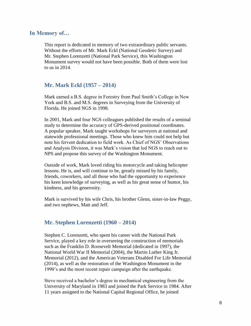
In Memory of…
This report is dedicated in memory of two extraordinary public servants.
Without the efforts of Mr. Mark Eckl (National Geodetic Survey) and
Mr. Stephen Lorenzetti (National Park Service), this Washington
Monument survey would not have been possible. Both of them were lost
to us in 2014.
Mr. Mark Eckl (1957 – 2014)
Mark earned a B.S. degree in Forestry from Paul Smith’s College in New
York and B.S. and M.S. degrees in Surveying from the University of
Florida. He joined NGS in 1998.
In 2001, Mark and four NGS colleagues published the results of a seminal
study to determine the accuracy of GPS-derived positional coordinates.
A popular speaker, Mark taught workshops for surveyors at national and
statewide professional meetings. Those who knew him could not help but
note his fervent dedication to field work. As Chief of NGS’ Observations
and Analysis Division, it was Mark’s vision that led NGS to reach out to
NPS and propose this survey of the Washington Monument.
Outside of work, Mark loved riding his motorcycle and taking helicopter
lessons. He is, and will continue to be, greatly missed by his family,
friends, coworkers, and all those who had the opportunity to experience
his keen knowledge of surveying, as well as his great sense of humor, his
kindness, and his generosity.
Mark is survived by his wife Chris, his brother Glenn, sister-in-law Peggy,
and two nephews, Matt and Jeff.
Mr. Stephen Lorenzetti (1960 – 2014)
Stephen C. Lorenzetti, who spent his career with the National Park
Service, played a key role in overseeing the construction of memorials
such as the Franklin D. Roosevelt Memorial (dedicated in 1997), the
National World War II Memorial (2004), the Martin Luther King Jr.
Memorial (2012), and the American Veterans Disabled For Life Memorial
(2014), as well as the restoration of the Washington Monument in the
1990’s and the most recent repair campaign after the earthquake.
Steve received a bachelor’s degree in mechanical engineering from the
University of Maryland in 1983 and joined the Park Service in 1984. After
11 years assigned to the National Capital Regional Office, he joined

9
National Mall and Memorial Parks as Chief of Resource Management, and
became the Deputy Superintendent in 2005.
He was a Bethesda resident and a volunteer with Manna Food Center, a
food bank in Gaithersburg, and a girls’ coach with MSI Soccer in
Montgomery County, Maryland. His avocations included ultimate Frisbee
and mountain biking.
Survivors include his wife of 27 years, Maureen Shields Lorenzetti, two
daughters, Gina and Claire, and his mother, Esther and two brothers, Peter
and David.

10
Part I
Background and Justification of the Project

11
1. Background
The Washington Monument is located near the center of the National Mall in Washington D.C.,
United States of America, at approximately 77 degrees 2 minutes west longitude and 38 degrees
53 minutes north latitude.
The National Geodetic Survey (NGS), formerly the U.S. Coast and Geodetic Survey (USC&GS),
has been, and continues to be, directly involved with surveying efforts in, on, and around the
Washington Monument (WM) for more than 100 years. This survey work has often been in
collaboration with the U.S. Army Corps of Engineers (USACE), formerly the Corps of
Engineers, whose responsibility it was to complete the construction in 1884, and the National
Park Service (NPS), the agency that administers and maintains the monument. Most of these
surveys have been on and around the grounds of the monument. In only a few rare instances
was there an opportunity to occupy the peak and perform a survey from that vantage point.
Scaffolding erected in 2013 offered one of those rare opportunities to occupy the peak, and NGS
requested to collaborate with the NPS to survey the peak’s latitude, longitude, and elevation
more accurately than was possible in any previous surveys. NGS proposed a combination of
leveling, GPS, and reciprocal vertical angles, which promised a determination of the
monument’s elevation to within a few millimeters of accuracy.
2. Primary Goals:
Although the latitude, longitude, and elevation1 of the WM peak had been determined in
previous surveys, the accuracy of those surveys was not deemed adequate enough to determine
whether there had been any movement of the structure’s peak. Therefore, the primary goal of
the 2013–2014 survey was to provide a baseline, to measure certain values so accurately that
any future surveys could then be used to detect change. The three primary sub-goals of this
survey were:
1. Determine the Architectural Height2 of the Washington Monument
2. Determine the Elevation of the Peak of the Washington Monument
3. Determine the Latitude and Longitude of the Peak of the Washington Monument
A description of each of these goals is found later in this report.
3. Secondary Goals:
As mentioned, no survey of comparable accuracy to the 2013–2014 survey had ever before been
performed at the WM. Thus, the ability to detect changes to the monument was expected to be
1 The use of “elevation” in this report will mean either the ellipsoid height (in NAD 83) or orthometric height (in
NAVD 88) or both, but will not be used to mean the “Architectural Height” of the building. 2 As per the standards of the Council of Tall Buildings and Urban Habitat. Although there is circumstantial evidence
that attempts were made in 1999 to collect up the information necessary to compute this value, the only existing
record of an architectural height being determined by NGS at that time are references in news articles stating that a
height of 555 feet 5.9 inches had been determined. Further, no marks on the floor of the WM exist in the NGS
Integrated Database from the 1999 leveling, indicating no attempt to follow CTBUH standards at that time.

12
reduced by the accuracy of previous surveys. Not that those previous surveys were poor, but
none of them had specifically used the method of reciprocal vertical angles. This difference
alone would translate to a likely order of magnitude difference between the accuracies of
previous surveys as compared to this new survey. Part of the difficulty was due to the scaffolding
itself; both the 1999 and 2013 GPS surveys at the peak suffered significant multipath errors due
to the peak (and the antenna mounted thereon) being surrounded on all sides, as well as above,
by the metal scaffolding.
Nevertheless, NGS decided to review the previous surveys and set as a secondary goal the
determination of any change at the peak. This secondary goal was comprised of three sub-goals:
1. Determine any change to the Architectural Height of the Washington Monument
2. Determine any change to the Elevation of the Peak of the Washington Monument
3. Determine any change to the Latitude and Longitude of the Peak of the Washington
Monument
A full description of these and the success reached as a result is found later in the report.
4. Identifying Geodetic Control Marks
Geodetic survey marks are permanent uniquely-identifiable points on the Earth, to which
measurements (such as angles and distances to other marks) are made or data collected (such as
GPS observations), and then coordinates are computed. There are a number of geodetic marks
that have been used in and around the Washington Monument and National Mall area for more
than 100 years. Before the 1960’s, these marks were identified mostly by a name (officially
referred to as a “designation”). The difficulty with such identification is that designations have
been known to change throughout history. Today, NGS uses a system of six-digit Permanent
Identification numbers, or PIDs, to uniquely identify each survey point, and these PIDs do not
change over time. Further complicating the identification issues are the fact that each individual
survey often assigns a “Station Serial Number” (SSN) to a mark for the use of only that
individual survey. Additionally, when GPS is used for surveying, each mark is often given a
four-character identification to name the Receiver Independent Exchange Format (RINEX) files
for each GPS occupation.
To simplify the confusion of survey mark identification, a full list and description of each mark
mentioned in this report is provided in Appendix E.
Throughout this report, the designation was used to identify and discuss all marks. Occasionally
the PID or four-character GPS ID or other information was provided. However, to accommodate
an easier-to-read report, marks are generally referred to only by their current designation, and
capital letters are used. Thus, while “The Zero Milestone” may refer to the general landmark
found south of the White House, the geodetic mark found at that location is referred to as “ZERO
MILESTONE” throughout the report.

13
5. History of Surveys at the Washington Monument
The Washington Monument is one of the most prominent landmarks in Washington, D.C.
Surveyors on the ground around the National Mall have used the peak of the monument as a
reference point for measuring angles for more than 100 years. However, the history of
determining the architectural height of the monument is somewhat clouded, due to un-digitized
archives or numerous, conflicting news reports (see Appendix H). This report does not attempt
to clarify that history, but rather stand as a documentation milestone and enable future
investigations to be clear regarding what was accomplished, how the surveys were conducted,
and what values were determined.
1880–1900
The survey notes of the USACE and USC&GS were not digitized, so an historic search for
important evidence of prior surveys has proved to be a challenge. However, a significant amount
of evidence has been unearthed. In 1885, just one year after the completion of the WM,
in his handwritten annual report, Lt. Col. Casey (USACE) states the monument is 555 feet,
5 1/8 inches tall. Attempts to locate the exact survey or the computations leading up to this
number have, however, thus far proved unsuccessful.
In one of the earliest USC&GS surveys (in 1896), a note in the annual “Report of the
Superintendent” describes a brass bolt near the southwest corner of the WM, referring to it
as “point O.” It further states “the aluminum point of the pyramidion is said to be 555 feet, 4 ½
inches above this bolt,” although it makes no mention of who it was who stated the pyramidion
was that high above the bolt. The bolt description agrees fairly well with a description found in
an 1881 USACE report: “a bronze bolt was set in the blue stone at the southwest exterior corner
of the shaft, and its upper surface made exactly level with the bottom surface of the marble
facing of the monument at that corner.” More details regarding this brass-versus-bronze question
are found in Appendix H.
1901–1933
The USC&GS performed a variety of geodetic leveling surveys to marks in and around the
WM in 1901, 1903, 1904, 1907, 1912, 1914, 1923, 1926, and 1927, frequently for the purpose
of checking for land motion and connecting to the local tidal marks. Various marks were part
of the earliest of these surveys. Of all the marks used in surveys around the WM, today very
few remain with a history of use dating back to the earliest leveling campaigns around the WM.
Two marks were repeatedly observed in geodetic leveling surveys over the last century. The
first is the bench mark designated “A” (PID HV1841, colloquially referred to as the “Mini
Monument”), and it was used in every geodetic leveling survey conducted by USC&GS around
the Washington Monument since 1901, with the exception of the 1923, 1927, and 1956/1957
leveling campaign. The second is the mark designated “I” (more recently designated
“I=M 8=TIDAL”; PID HV1838), first leveled in 1907 and sporadically leveled through the
last century.

14
According to Doyle (2012a, 2012b), “When C&GS revisited the Monument in 19213, the marks
from 1901 had all been destroyed.” An examination of the 1901 field books indicate that the
designations of marks used that year were A, B, C, D, E, F, G, H, and B 1. There is compelling,
but not yet definitive, evidence that mark B 1 was not destroyed, but was actually re-discovered
in 1999 and, not being recognized as an historic mark with an existing designation, was treated
as a new mark and given a new designation. Three marks from the 1907 leveling survey (with
designations M, N, and O) may also be in this same group of marks re-discovered and re-named
in 1999. See Appendix E (marks with designations beginning “W M BASE”) for further detail.
1934–1998
The first major restoration of the WM was performed in 1934, and at that time scaffolding was
erected around the entire structure (Figure 1) to perform the necessary restorative work, with the
additional distinct advantage that the peak itself was accessible and could be occupied by a
surveying instrument. The USC&GS crew ascended the inside of the monument with their
instruments, climbed out a door to the platform at the peak, and sighted various landmarks
around Washington D.C. for the express purpose of determining the latitude and longitude of the
peak (Figure 3). Although another round of cleaning and restoration took place in 1964, it was
done without a comprehensive scaffold being built (Figure 2). Only temporary platforms,
attached to the side of the monument by drilling into it, were used. No real opportunity to access
the peak for surveying was possible at that time.
3 NGS has no evidence of a 1921 survey of the monument by USC&GS. It seems probable that the author was
referring to the 1923 survey of the Washington Monument, when mark “C 1” was established.

15
Figure 1: Aerial view of scaffolding used in 1934
Figure 2: Temporary scaffolding used
in 1964 cleaning of WM
Figure 3: USC&GS survey crew atop the WM performing a 1934
triangulation survey
16
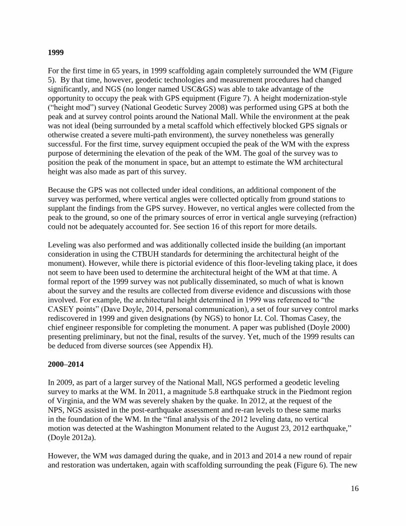
1999
For the first time in 65 years, in 1999 scaffolding again completely surrounded the WM (Figure
5). By that time, however, geodetic technologies and measurement procedures had changed
significantly, and NGS (no longer named USC&GS) was able to take advantage of the
opportunity to occupy the peak with GPS equipment (Figure 7). A height modernization-style
(“height mod”) survey (National Geodetic Survey 2008) was performed using GPS at both the
peak and at survey control points around the National Mall. While the environment at the peak
was not ideal (being surrounded by a metal scaffold which effectively blocked GPS signals or
otherwise created a severe multi-path environment), the survey nonetheless was generally
successful. For the first time, survey equipment occupied the peak of the WM with the express
purpose of determining the elevation of the peak of the WM. The goal of the survey was to
position the peak of the monument in space, but an attempt to estimate the WM architectural
height was also made as part of this survey.
Because the GPS was not collected under ideal conditions, an additional component of the
survey was performed, where vertical angles were collected optically from ground stations to
supplant the findings from the GPS survey. However, no vertical angles were collected from the
peak to the ground, so one of the primary sources of error in vertical angle surveying (refraction)
could not be adequately accounted for. See section 16 of this report for more details.
Leveling was also performed and was additionally collected inside the building (an important
consideration in using the CTBUH standards for determining the architectural height of the
monument). However, while there is pictorial evidence of this floor-leveling taking place, it does
not seem to have been used to determine the architectural height of the WM at that time. A
formal report of the 1999 survey was not publically disseminated, so much of what is known
about the survey and the results are collected from diverse evidence and discussions with those
involved. For example, the architectural height determined in 1999 was referenced to “the
CASEY points” (Dave Doyle, 2014, personal communication), a set of four survey control marks
rediscovered in 1999 and given designations (by NGS) to honor Lt. Col. Thomas Casey, the
chief engineer responsible for completing the monument. A paper was published (Doyle 2000)
presenting preliminary, but not the final, results of the survey. Yet, much of the 1999 results can
be deduced from diverse sources (see Appendix H).
2000–2014
In 2009, as part of a larger survey of the National Mall, NGS performed a geodetic leveling
survey to marks at the WM. In 2011, a magnitude 5.8 earthquake struck in the Piedmont region
of Virginia, and the WM was severely shaken by the quake. In 2012, at the request of the
NPS, NGS assisted in the post-earthquake assessment and re-ran levels to these same marks
in the foundation of the WM. In the “final analysis of the 2012 leveling data, no vertical
motion was detected at the Washington Monument related to the August 23, 2012 earthquake,”
(Doyle 2012a).
However, the WM was damaged during the quake, and in 2013 and 2014 a new round of repair
and restoration was undertaken, again with scaffolding surrounding the peak (Figure 6). The new
17
restoration provided the opportunity to survey the peak with more modern survey equipment,
resulting in a higher level of accuracy than had been previously been possible. The details of
how this survey was planned are described in the next section.
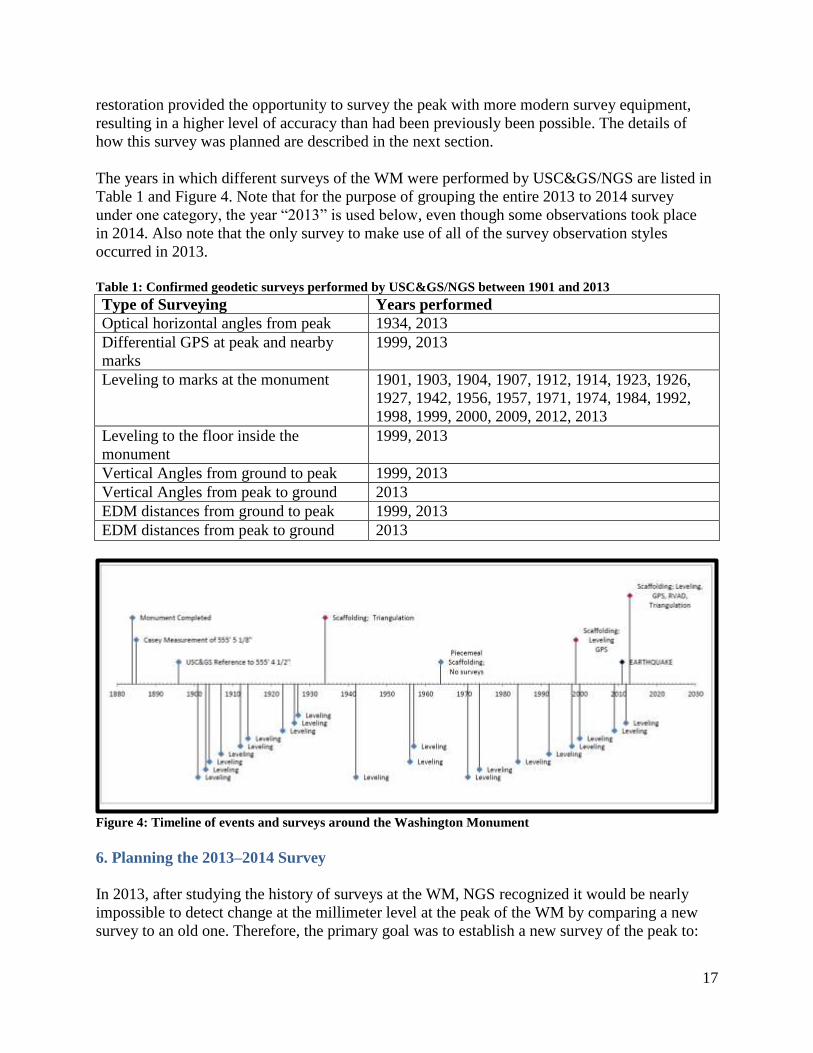
The years in which different surveys of the WM were performed by USC&GS/NGS are listed in
Table 1 and Figure 4. Note that for the purpose of grouping the entire 2013 to 2014 survey
under one category, the year “2013” is used below, even though some observations took place
in 2014. Also note that the only survey to make use of all of the survey observation styles
occurred in 2013.
Table 1: Confirmed geodetic surveys performed by USC&GS/NGS between 1901 and 2013
Type of Surveying Years performed
Optical horizontal angles from peak 1934, 2013
Differential GPS at peak and nearby
marks
1999, 2013
Leveling to marks at the monument 1901, 1903, 1904, 1907, 1912, 1914, 1923, 1926,
1927, 1942, 1956, 1957, 1971, 1974, 1984, 1992,
1998, 1999, 2000, 2009, 2012, 2013
Leveling to the floor inside the
monument
1999, 2013
Vertical Angles from ground to peak 1999, 2013
Vertical Angles from peak to ground 2013
EDM distances from ground to peak 1999, 2013
EDM distances from peak to ground 2013
Figure 4: Timeline of events and surveys around the Washington Monument
6. Planning the 2013–2014 Survey
In 2013, after studying the history of surveys at the WM, NGS recognized it would be nearly
impossible to detect change at the millimeter level at the peak of the WM by comparing a new
survey to an old one. Therefore, the primary goal was to establish a new survey of the peak to:

18
definitively position the peak, determine the architectural height of the monument, and serve as
a “baseline” to allow future surveys to monitor changes. The primary sub-goals to create this
baseline were mentioned earlier. The surveying styles and techniques planned and executed as
part of the 2013–2014 survey of the WM were as follows:
1. Geodetic Leveling
a. Determine the height difference between the floor level of the WM and
surrounding geodetic control marks, and validate existing NAVD 88 orthometric
heights.
2. Reciprocal Vertical Angles and Distances and Horizontal Angles
a. Determine the architectural height differences and elevation differences between
surrounding geodetic control marks and the peak of the WM.
b. Determine the latitude and longitude of the peak based on surrounding control.
3. GNSS (GPS only)
a. Used as a check on the other survey methods
b. Planned as a secondary survey technique to determine elevation differences
between surrounding geodetic control points and the peak (to be used in this
manner only if the Reciprocal Vertical Angles and Distances needed to be
augmented)
The geodetic leveling and the reciprocal vertical angles and distances alone provide enough
information to determine the architectural height of the WM. Latitude, longitude, and elevation
of the peak were determined through the horizontal and vertical angles from the peak and from
the ground at points with known NSRS coordinates. The GPS data were used as a check on the
Reciprocal Vertical Angles and Distances (RVAD) and Horizontal Angles (HA) measurements.

19
Figure 5: The 1999 scaffolding
Figure 6: The 2013–2014 scaffolding
Figure 7: A GPS receiver mounted at the peak in 1999

20
7. Planning for Future Surveys
This section provides specialized instructions to help plan for any future surveys at the WM.
Contact the National Park Service for approval to access all marks located on the National Mall.
At the time of this survey, the following marks (as well as all bench marks on, at, or in the
monument) were within a perimeter fence, requiring access permission by the NPS:
WASHINGTON MONUMENT
JEFFERSON PIER
A
The following special restrictions apply to the marks around the WM and National Mall area in
general:
WASHINGTON MONUMENT is the peak of the Washington Monument and is only accessible
when scaffolding surrounds the structure.
JEFFERSON PIER projects above the ground surface approximately 0.5 meters, requiring an
“extended” length tripod for occupation.
MERIDIAN STONE is located inside a secured area in the White House ellipse and requires
NPS approval for access.
ZERO MILESTONE is a popular tourist attraction drawing a great many visitors on any given
day. The monument projects above the ground surface approximately 1.5 meters. Due to its
height above the ground surface and the large number of tourists at the mark, it is recommended
a trivet be used to occupy this mark with GPS, total stations, or reflectors. When leveling to this
mark, it is recommended a 60-centimeter rod (GWCL60 invar scale with barcode) be available.
At times when the U.S. President is in transit by motorcade or by helicopter, Park police may
require you leave the immediate area of this monument.
USFS COMMEMORATIVE MARK is on the west lawn of the U.S. Department of Agriculture
building and projects above the ground surface approximately 0.5 meters, requiring an
“extended” length tripod for occupation.
A 8 and B 8 only exist as accessible bench marks when their caps have been unscrewed and a
custom-fabricated horizontal rod has been inserted into the holes behind the caps. These rods, as
well as the tool for removing the cap, are kept at NGS headquarters in Silver Spring, Maryland.
W M BASE <NW,SW,SE,NE>, as well as W M ROD NW, are only accessible at times when
the pavers have been removed from around the base of the monument.
W M CASEY <NW,SW,SE,NE> are on the grounds of the WM at the bottom of tubes which
have been capped and whose caps are flush with the pavers. Contact the NPS prior to accessing
these marks.

21
A (or the “mini-monument”) is the top of a truncated miniature structure of the WM located in a
brick well under a manhole cover on the south grounds of the WM. Contact the NPS prior to
accessing this mark.
W M FLOOR <1,2,3,4> are not identifiable on sight as geodetic control marks, but they are
identifiable points on the floor in the interior of the monument. Contact the NPS prior to
accessing these marks.

22
PART II
Fulfilling the Primary Goals of this Project:
1. Determining Architectural Height of the Washington Monument
2. Determining Elevation of the Peak of the Washington Monument
3. Determining Latitude and Longitude of the Peak of the Washington Monument
23
8. Reconnaissance
The NGS project manager for the 2013–2014 survey of the WM was Mark Eckl, chief of the
National Geodetic Survey’s Observation and Analysis Division. Mr. Eckl contacted the National
Park Service and proposed NGS be allowed to survey the peak. He coordinated initial email
discussions with Michael Morelli (Senior Landscape Architect), Cherie Shepherd (Project
Manager, Design and Construction Division) and Nancy Caretta (contractor with Hill
International, working onsite for the NPS during the renovation). The NPS arranged for NGS to
further coordinate with the contractors working on the renovations (Robert Collie of Perini, and
Steven Munroe of Grunley).
After Mr. Eckl shared the basics of the NGS plan, the NPS agreed it was a worthwhile project,
and a reconnaissance date was set. An initial meeting for safety training instruction was held on
October 25, 2013, at the temporary office of Grunley and Perini at the WM site. Immediately
thereafter, reconnaissance of the WM began. Representing NGS were: Juliana Blackwell
(Director), Mark Eckl, Eric Duvall, Roy Anderson, Kendall Fancher, and Dru Smith. The
primary consideration was the scaffolding removal scheduled to begin in late November.
Therefore, all components of the survey requiring access to the peak were to be attempted before
the beginning of November. NGS crews ascended the scaffolding to the peak to measure the size
and shape of the peak; take photographs of the peak; measure how much space existed between
the peak and the surrounding scaffolding; and discuss options for mounting GPS equipment,
reflectors, or total stations over the peak. The amount of surrounding metal would affect GPS
performance due to signal block and multipath, identical issues to those encountered in 1999.
There would be no “open sky view” except through sparse gaps in the scaffolding. Ideas for
mounting GPS on booms projecting from the scaffolding were discussed, but the ultimate
decision was made to use a single mount on the peak, and when it was time to collect the GPS
data, the goal was to mitigate much of the multipath by collecting multiple datasets over a period
of several days.
One immediate fact was apparent during reconnaissance: the peak was not nearly as “pointed” as
it had been when first constructed, but rather it was rounded and pitted.4 This raised the question
of what constituted “the peak” and to what NGS would be surveying. In the end, NGS surveyed
to the top center of the rounded peak, but also computed the estimated architectural height loss
based on the rounding of the peak. For more details on this issue, see Appendix F.
NGS also learned that the previous Lightning Protection System, or LPS, (see Figure 8)
originally installed in 1885 (Binczewski 1995) and refurbished in 1934, had been removed and
was to be abandoned and replaced with a new system. The 1999 GPS survey had made use of
this old LPS by using an adaptor made to clamp to the LPS (see Figure 7). The 1999 adapter was
built by the National Institute of Standards & Technology (NIST) and was returned after the
survey was finished, but by 2013 it had been discarded. Therefore, it was necessary to design and
build a new adapter to hold a GPS antenna, a reflector, or a total station, each as stably as
possible, yet without clamping to other parts of the WM or scaffolding. The new LPS was
4 A note from the 1934 survey clearly indicates that this same problem was found back then, and “frequent lightning
strikes” were attributed to the misshapen nature of the very tip of the peak. (See NGS datasheet for mark HV4442 at
www.ngs.noaa.gov)

24
attached to the WM below the aluminum pyramidion cap with removable rods (see Figure 9).
The placement of these rods was not a consideration for the new adapter, but where the rods
would mount to the WM itself did need to be taken into account.
An historical side note was also observed during reconnaissance: for over a century, the old LPS
sat directly on the aluminum faces of the pyramidion cap, and this apparently had caused entire
portions of the original engravings (circa 1884) to be rubbed away. See Appendix G for more
information.
NGS learned there were holes between the interior and exterior of the WM at the 500-foot floor
level. The holes allowed a GPS antenna at the peak to be connected by a 30-meter cable through
one of the holes to a receiver that was sheltered (and plugged in) inside the WM.
Particularly affecting the plan for geodetic leveling, NGS also learned the schedule would call
for the following:
1. The pavers making up the walkway around the base of the monument would not be put
back in place until April 2014, allowing NGS to access some of the deeper historic marks
(or to at least look for evidence of them).
2. The protective cover over the interior floor would remain in place until near the end of
the project, also around April 2014.
3. The time of scaffolding removal was set from November through April, and during this
time NGS would generally not be allowed to work below the scaffolding (for safety
purposes).
Finally, part of the reconnaissance crew fanned out around the National Mall area to seek out the
geodetic control points that could be used in this survey. Criteria included:
1. Finding four marks in the cardinal directions from the WM with a clear view of the peak
2. Finding those marks used as control during the 1999 survey or other recent leveling
surveys
In the end, reconnaissance was successful in aiding the design of the survey to be executed from
the peak. The following decisions were made (note that some of these were later modified as the
survey progressed and more evidence came to light):
1. A new adapter capable of mounting a GPS antenna or a reflector or a Total Station (one
instrument at a time) would be immediately built. The adapter would rest on the peak and
be stable.
2. As soon as the adapter was complete, GPS data would be continuously collected on the
peak for as many days as possible, with the only interruption being when the Reciprocal
Vertical Angles and Distances (or “terrestrial survey”) was being performed.
3. Reciprocal Vertical Angles and Distances (RVAD) would take place to at least four
marks around the WM, more or less in the four cardinal directions. The initial terrestrial
control chosen (this did change later) were marks designated ZERO MILESTONE,
W M WEST, W M SOUTH, and W M EAST.
4. Horizontal Angles (HA) would be collected in conjunction with the RVAD survey.

25
5. Using the same marks as the RVAD, a one-day GPS campaign would be performed
contemporaneously with GPS at the peak.
6. NGS would need to level to the floor and to whatever points were used in the RVAD
survey, but the effort would need to be timed between the end of scaffolding removal and
the replacement of pavers (a very small window of only two or three weeks in April).
7. NGS would also attempt to seek evidence of buried geodetic control marks which had
been “lost” since 1921. Of particular interest was vertical mark “O” at the SW corner of
the monument (see Appendix C). Leveling to these and other marks on the foundation of
the WM would be part of the overall leveling campaign.
8. A re-processing of the 1999 survey would be attempted to more definitively state the
results of that survey in comparison to the new survey.
9. Preparation
Immediately following reconnaissance, NGS began designing a new adapter, beginning with
the construction of a wooden mock-up of the peak. Discussions about stability led to a few
innovative ideas, but in the end the adapter’s design and weight were sufficient for it to sit
stably atop the WM without any form of clamping or external stabilizers. (Nonetheless, guy
wires were used to further stabilize the adapter by attaching it to the new LPS). The new adapter
was built at the NGS Corbin, Virginia, facility as a joint effort between Don Breidenbach and
Steve Breidenbach. The new adapter—hereafter referred to as “the Breidenbach Adapter” in
honor of the two builders—consists of three parallel horizontal aluminum plates, each spaced
apart from the other and with a square hole of beveled edges to allow the adapter to fit snugly
over the peak. A manual translation stage was integrated with the top plate enabling precise
collimation over “the peak.” A series of nuts and bolts allowed for minor alteration of the
spacing between the plates to ensure a tight fit at the peak. The Breidenbach Adapter weighs
approximately 10 pounds, making it very stable under its own weight at the peak (see Figure 10
and Figure 11). After the survey was complete, the Breidenbach Adapter was moved to the NGS
facility at Corbin, Virginia.
The height of instruments above the peak was to be determined by using a Leica DISTO D8
distance meter.
An inventory of equipment was then performed. To eliminate any biases due to antenna
calibration issues, a common set of GPS antennae were to be used for all GPS portions of the
survey. A complete list of all equipment used in the survey is listed in Appendices A, B, and C.
As the survey was required to be performed rapidly, NGS headquarters personnel augmented
regular field crew personnel. Finally, NOAA Public Relations were contacted and a “Media
Day” was organized for November 7, 2013, to highlight the survey. NOAA’s Office of Public
and Constituent Affairs organized photo opportunities, and television, radio, and press interviews
at the mark designated ZERO MILESTONE. NGS personnel answered questions and provided a
demonstration by measuring the distance from ZERO MILESTONE to the mark designated
WASHINGTON MONUMENT (the Peak of the WM) using the Leica TDM5005 total station
with a reflector at the peak.

26
Figure 8: Lighting Protection System collar resting
on aluminum cap (circa 1999)
Figure 9: New Lightning Protection System
installed 2014
Figure 10: Wooden mock-up of peak with the
Breidenbach Adapter in place
Figure 11: Don Breidenbach at the peak of the
Washington Monument with the adapter he designed

27
10. Terrestrial Survey: Reciprocal Vertical Angles and Distances and Horizontal Angles
The collecting of Reciprocal Vertical Angles and Distances (RVAD) and Horizontal Angles
(HA) took place on November 5 and 6, 2013. The proposed list of points to be surveyed for
RVAD and HA from the peak was:
1. ZERO MILESTONE (HV1847)
2. W M WEST (AI4421)
3. W M SOUTH (AI4422)
4. W M EAST (AI4420)
Additionally, although it could not be seen from the peak, RVAD and HA were proposed to be
collected between ground stations and to another mark:
JEFFERSON PIER (UA0024).
Upon deploying the total station at the peak, it was immediately obvious that two of the
originally planned RVAD points were not actually visible from the instrument at the peak (either
due to ground obstructions or due to the scaffolding being in the way), so points W M EAST and
W M SOUTH were dropped. The two new points used instead were:
1. MERIDIAN STONE (HV1846)
2. USFS COMMEMORATIVE MARK (DL6618)
Direct lines of sight did not exist between all points on the ground, so several ground-to-ground
horizontal angles could not be measured, however these points were all visible from the peak, so
horizontal angles were measured from there to the marks. By dropping W M SOUTH, the south
quadrant no longer had a point, and no suitable replacement could be found. Meridian Stone was
added, providing a second north quadrant point, somewhat closer to the WM than ZERO
MILESTONE. Fortunately, the USFS COMMEMORATIVE MARK, East-Southeast of the
WM, provided some southern geometry for the terrestrial network.
A more complete report on the RVAD/HA survey, containing the entire set of data measured
through the RVAD and HA survey, is in Appendix A. For the use of this data in the fulfillment
of the primary goals of this part of the project, see Section 13 of this report.
11. Leveling
The collection of geodetic leveling data occurred between April 8 and April 22, 2014. This
portion of the survey fulfilled two requirements:
a. To confirm, or supersede, the North American Vertical Datum of 1988 (NAVD 88)
orthometric heights on points around the monument involved in the terrestrial survey
b. To provide a direct connection to an “architectural zero” height (i.e. the floor) of the
WM, as per the standards of the Council on Tall Buildings and Urban Habitat.
Leveling was performed to first order, class II FGCS (formerly FGCC) standards (Federal
Geodetic Control Committee 1984) over 5 days involving 22 different points.
A complete report on the leveling survey in Appendix B contains the entire set of data measured
through the leveling survey. For the use of this data in the fulfillment of the three goals of this
part of the project, see Section 13 of this report.
28
12. GPS
The collecting of GPS data took place from November 1 through November 8, 2013.
A GPS antenna mounted on the peak of the WM collected data at an epoch rate of 5 seconds
from November 1 through November 5, 2013. On the morning of November 5, the antenna was
removed to allow the RVAD/HA survey to be performed. The antenna was replaced a few hours
after the RVAD/HA survey was complete, and data collection continued. The antenna was
removed on the morning of November 6 for the conclusion of the terrestrial survey and replaced
that afternoon, where it continued to run overnight. On November 7, a GPS campaign was
performed while the GPS antenna was running on the peak. The stations occupied in the GPS
campaign were (using the four-character GPS ID values):
WASH = WASHINGTON MONUMENT (HV4442) – This is the “peak”
ZERO = ZERO MILESTONE (HV1847)
000A = A (HV1841)
WMWE = W M WEST (AI4421)
WMEA = W M EAST (AI4420) 5
USFS = USFS COMMEMORATIVE MARK (DL6618)
MERI = MERIDIAN STONE (HV1846)
JEFF = JEFFERSON PIER (UA0024)
WMSO = W M SOUTH (AI4422)
After three to five hours of conterminous occupation, the ground stations were dismantled (with
the exception of mark “A,” which continued overnight to November 8). Because Media Day was
scheduled for the afternoon of November 7, including a demonstration of RVAD from ZERO
MILESTONE up to the peak, the GPS antenna at the peak was also removed and replaced with a
reflector for the demonstration. No further GPS data were collected on the peak after this.
A complete report on the GPS survey is found in Appendix C. For the use of this data in the
fulfillment of the three goals of this portion of the project, see Section 13 of this report.
13. Computation of Values of Interest
The first step in computing our values of interest was to ensure NGS was computing the
architectural height of the WM to modern, internationally agreed-upon standards. In
communications between Mr. Mark Eckl and the CTBUH, the mark designated
“W M FLOOR 3” (PID DP2634) was chosen to represent the Architectural Zero Height Point at
the Washington Monument for determining the architectural height of the building. With that
decision firmly established, processing of all data could proceed.
All three types of surveys (terrestrial, leveling, and GPS) were necessary to adequately compute
the values of interest to this survey. However, each was processed and adjusted independently to
5 Due to a miscommunication in the field, GPS was erroneously set up over W M EAST. This occupation was
quickly dismantled and moved to USFS COMMEMORATIVE MARK. However some data does exist for the brief
W M EAST occupation.
29
provide input to the next step in the process, a fairly complicated process, described below and
also shown in graphic form. Adjustment steps are described in more detail in their own
subsections.
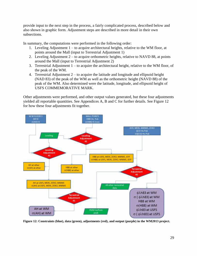
In summary, the computations were performed in the following order:
1. Leveling Adjustment 1 – to acquire architectural heights, relative to the WM floor, at
points around the Mall (input to Terrestrial Adjustment 1)
2. Leveling Adjustment 2 – to acquire orthometric heights, relative to NAVD 88, at points
around the Mall (input to Terrestrial Adjustment 2)
3. Terrestrial Adjustment 1 – to acquire the architectural height, relative to the WM floor, of
the peak of the WM.
4. Terrestrial Adjustment 2 – to acquire the latitude and longitude and ellipsoid height
(NAD 83) of the peak of the WM as well as the orthometric height (NAVD 88) of the
peak of the WM. Also determined were the latitude, longitude, and ellipsoid height of
USFS COMMEMORATIVE MARK.
Other adjustments were performed, and other output values generated, but these four adjustments
yielded all reportable quantities. See Appendices A, B and C for further details. See Figure 12
for how these four adjustments fit together.
Figure 12: Constraints (blue), data (green), adjustments (red), and output (purple) in the WM2013 project.

30
13.1 Leveling Adjustment #1: Determine Architectural Heights of Points around the
National Mall.
Holding W M FLOOR 3 fixed at a height of 0.000, all geodetic leveling data were adjusted, and
the following relative vertical differences were determined:
Table 2: Architectural Heights of marks around the National Mall
DESIGNATION PID ARCHITECTURAL
HEIGHT (m)
STANDARD
DEVIATION
(mm)
W M FLOOR 3 DP2634 0.000 ± 0.0
W M WEST AI4421 -10.099 ± 0.3
ZERO MILESTONE HV1847 -3.832 ± 0.4
MERIDIAN STONE HV1846 -7.010 ± 0.4
USFS COMMEMORATIVE MARK DL6618 -0.686 ± 0.3
JEFFERSON PIER UA0024 -5.193 ± 0.2
Leveling was performed to other marks in and around the Washington Monument, but they did
not directly play a role in the computation of the architectural height of the peak of the WM. For
more details, see Appendix B.
13.2 Leveling Adjustment #2: Determine NAVD 88 Orthometric Heights of Points around the
National Mall.
Holding nine points nearly fixed (standard deviation = 0.1 mm) at their published NAVD 88
orthometric heights, all the geodetic leveling data were adjusted, and the following orthometric
heights were determined:
Table 3: NAVD 88 orthometric heights of marks around the National Mall
DESIGNATION PID NAVD 88
ORTHOMETRIC
HEIGHT (m)
STANDARD
DEVIATION
(mm)
W M WEST AI4421 2.116 ± 0.1
ZERO MILESTONE HV1847 8.382 ± 0.1
MERIDIAN STONE HV1846 5.204 ± 0.1
USFS COMMEMORATIVE MARK DL6618 11.529 ± 0.7
JEFFERSON PIER UA0024 7.022 ± 0.3
Other marks in and around the Washington Monument were leveled to, but they did not directly
play a role in the computation of elevation of the peak of the WM. For more details, see
Appendix B.
31
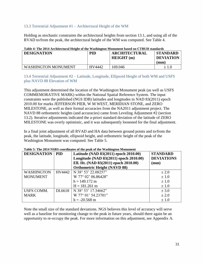
13.3 Terrestrial Adjustment #1 – Architectural Height of the WM
Holding as stochastic constraints the architectural heights from section 13.1, and using all of the
RVAD to/from the peak, the architectural height of the WM was computed. See Table 4.
Table 4: The 2014 Architectural Height of the Washington Monument based on CTBUH standards
DESIGNATION PID ARCHITECTURAL
HEIGHT (m)
STANDARD
DEVIATION
(mm)
WASHINGTON MONUMENT HV4442 169.046 ± 1.0
13.4 Terrestrial Adjustment #2 – Latitude, Longitude, Ellipsoid Height of both WM and USFS
plus NAVD 88 Elevation of WM
This adjustment determined the location of the Washington Monument peak (as well as USFS
COMMEMORATIVE MARK) within the National Spatial Reference System. The input
constraints were the published (NGS IDB) latitudes and longitudes in NAD 83(2011) epoch
2010.00 for marks JEFFERSON PIER, W M WEST, MERIDIAN STONE, and ZERO
MILESTONE, as well as their formal accuracies from the NA2011 adjustment project. The
NAVD 88 orthometric heights (and accuracies) came from Leveling Adjustment #2 (section
13.2). Iterative adjustments indicated the a-priori standard deviation of the latitude of ZERO
MILESTONE was overly optimistic, and it was subsequently loosened for the final adjustment.
In a final joint adjustment of all RVAD and HA data between ground points and to/from the
peak, the latitude, longitude, ellipsoid height, and orthometric height of the peak of the
Washington Monument was computed. See Table 5.
Table 5: The 2014 NSRS coordinates of the peak of the Washington Monument
DESIGNATION PID Latitude (NAD 83(2011) epoch 2010.00)
Longitude (NAD 83(2011) epoch 2010.00)
Ell. Ht. (NAD 83(2011) epoch 2010.00)
Orthometric Height (NAVD 88)
STANDARD
DEVIATIONS
(mm)
WASHINGTON
MONUMENT
HV4442 N 38° 53’ 22.08257”
W 77° 02’ 06.86428”
h = 149.172 m
H = 181.261 m
± 2.0
± 1.0
± 1.0
± 1.0
USFS COMM.
MARK
DL6618 N 38° 53’ 17.34662”
W 77° 01’ 54.23701”
h = -20.568 m
± 3.0
± 2.0
± 1.0
Note the small size of the standard deviations. NGS believes this level of accuracy will serve
well as a baseline for monitoring change to the peak in future years, should there again be an
opportunity to re-occupy the peak. For more information on this adjustment, see Appendix A.

32
14. Note on the Architectural Height
To summarize the information from section 13, the architectural height of the Washington
Monument, as determined by the 2013–2014 survey by the National Geodetic Survey and by
adhering to the CTBUH standards is:
169.046 m +/- 1.0 mm or
554' 7 11/32" +/- 1/32"
There are a number of reasons why this number does not match the historically stated
555 feet 5 1/8 inches, nor the 1999 determined value of 555 feet 3 5/8 inches (see Appendix H).
The first reason is that the source of the original 1885 value is unclear. It is not possible to
replicate it without knowing how the number was determined. Second, the peak itself is rounded,
so that the 2013–2014 survey refers to this rounded top, which is approximately 3/8 inches below
the original “point” of the peak (see also Appendix F). Third, the measurement technology used
in 2014 allowed for measurement techniques and accuracy not available in 1885. And finally,
this architectural height adheres rigorously to the standard set forth by the Council on Tall
Buildings and Urban Habitat (CTBUH). As the CTBUH has only existed since 1969, the
standard used in any prior measurements may not have been the same.
As expanded upon in Appendix H, an educated guess was made in 1999 about what the
“architectural zero height point” was in 1885 (being the average of the four marks known as the
“CASEY” marks which are very near to, but not physically part of, the WM building itself). If
the measurements taken in 2013–2014 were used to compute an architectural height based on the
1999 standard, then the architectural height would more closely match those of 1999 and 1885.
The 2014 architectural height, based on the 1999 standard, is 555 feet 4 1/64 inches +/- 1/32
inch. If the 1999 standard is, in fact, the 1885 standard, then this disagreement of about 1 1/8
inches with 1885 can easily be attributed to the 3/8 loss due to rounding of the peak plus the
measurement errors from 1885 and/or 2014. Additionally, as the “CASEY” marks are not part of
the monument, there is a remote chance they are subsiding at a different rate than the main body
of the monument, further accounting for the difference.
One final check on the architectural height can be made. In an 1896 superintendent’s report of
the Coast and Geodetic Survey, a reference is made to a “brass bolt” in the SW corner of the
monument, above which the peak of the WM was stated to be 555 feet 4 ½ inches. If one
presumes this bolt is mark “W M CASEY SW” (see Appendix H), then the 2013–2014 survey
computes the height above this mark at 555 feet 3 55/64 inches, a difference from the 1896
number of about 5/8 inches. Of that, 3/8 inches may be attributed to rounding of the peak,
yielding an agreement of about ¼ inch between 1896 and 2014.
33
PART III
Fulfilling the Secondary Goals of this project:
1. Determining Architectural Height Changes of the Washington Monument
2. Determining Elevation Changes of the Peak of the Washington Monument
3. Determining Tilt of the Peak of the Washington Monument

34
15. Detecting Change to the Washington Monument
To detect change over time, a minimum of two criteria must be met:
1. Two measurements of the same location or point must be made, separated in time.
2. The combined accuracies (including biases and random measurement errors) of the two
measurements must propagate through time into a smaller error than the change being
detected.
The first criterion is generally met in the determination of latitude and longitude (performed at
least in 1934, 1999, and 2013–2014), and ellipsoid height (performed at least in 1999 and
2013–2014) of the peak of the WM. It is important to note that only the peak is being discussed
at this point. NGS (and previously as the USC&GS) have monitored a very slow (approximately
0.5 mm/year) settling of the base of the WM since 1901 (Doyle 2012a). This settling could be
applied to the peak, but such a transfer pre-supposes knowledge of the expansion or contraction
behavior of 100,000 tons of marble, granite, and steel. As that kind of structural knowledge is not
maintained at NGS, a direct transfer of the base subsidence will not be blindly applied to the
elevation of the peak.
As far as NGS could determine, the first criterion was not met for the determination of the
architectural height of the WM. (Despite multiple definitive-sounding statements about the
architectural height of the monument, the inability to know exactly what was measured, by
whom, how, or when (see Appendix H) means that the 2013–2014 measurement of the
architectural height of the WM appears to be the only fully available documented measurement
of same.
The second criterion, however, is less easy to ensure. The formal accuracy statistics of the
2013–2014 survey are reported in the previous part of this report. A similar knowledge of the
accuracy of the 1934 and 1999 surveys would need to be determined prior to making any
definitive statements about “detecting change” between a historic survey and the 2013–2014
survey. To determine the accuracies of the historic surveys and whether they are small enough to
“detect change” will be investigated on a measurement-by-measurement basis below.
16. Re-processing of 1999 Vertical Angle Data
The vertical angle measurements from 1999 were added quickly to the overall survey plan,
executed without using reciprocal observations from the peak, and generally treated as a
secondary source of information behind GPS.
Once the 1999 data were retrieved and organized, the initial analysis showed a key piece of
metadata (height of the instrument) was missing. Without this information, the entire set of
measurements was biased and could not be adequately re-processed. The data set was therefore
abandoned for future analysis. Discussions with the project manager of the 1999 survey indicate
the vertical angle data “validated our GPS-derived value” (Dave Doyle, 2014, personal
communication), implying the height of instrument value was available in 1999.

35
17. Re-processing of 1999 GPS Data
Note criterion 1 in the “Detecting Change” section, above. While GPS was used in 1999 and in
2013 to measure differential heights between the WM peak and marks on the ground, the
software used in 1999 was not the software available in 2014. To ensure the two measurements
are compatible, the original 1999 GPS data were re-processed using the NGS software “OPUS
Projects.” This use of a common GPS processing engine between the 1999 data and 2013 data
allows for greater comparability between the two measurements. That no report was available
from the 1999 survey means significant effort was put into determining which antenna was on
which mark, with which height of instrument, at which times. To prevent this difficulty in future
processes, Appendix D shows the entire occupation specific information for the 1999 GPS
survey.
As closely as possible, the re-processing of the 1999 GPS campaign was forced to match that of
the 2013 survey. This was done by setting up two special least-squares adjustments with as much
commonality between them as possible, thus removing as many year-specific errors in the
adjustments as possible. The two special adjustments were:
GPS Adjustment #4: 1999 GPS processing to maximize 1999/2013 commonalities
GPS Adjustment #5: 2013 GPS processing to maximize 1999/2013 commonalities
A comparison of the commonalities and differences between the two are listed in Table 6.
Differences are shown in RED.
Table 6: Comparison between GPS Adjustment #4 (1999) and GPS Adjustment #5(2013)
Element 1999 2013
Passive Control JEFFERSON PIER (JEFF)
A (000A)
MERIDIAN STONE (MERI)
ZERO MILESTONE (ZERO)
JEFFERSON PIER (JEFF)
A (000A)
MERIDIAN STONE (MERI)
ZERO MILESTONE (ZERO)
CORS GODE
RIC1
USNA
GODE
GODZ
USNO
Elevation Mask 25° 25°
Network Type Triangulated Triangulated
Constraint Weights Tight Tight
After re-processing the 1999 GPS data, NAD 83(2011) epoch 2010.0 coordinates of the peak of
the WM are included in Table 7.

36
Table 7: NAD 83(2011) epoch 2010.00 coordinates for peak of WM based on 1999 GPS processed using
OPUS-Projects (GPS Adjustment #4)
Value Standard Deviation (mm)
Latitude N 38° 53’ 22.08088” +/- 1.0
Longitude W 077° 02’ 06.86692” +/- 1.0
Ellipsoid Height 149.257 m +/- 8.0
The coordinates in the same reference frame, at the same epoch from the 2013 GPS data are seen
in Table 8.
Table 8: NAD 83(2011) epoch 2010.00 coordinates for peak of WM based on 2013 GPS processed using
OPUS-Projects (GPS Adjustment #5)
Value Standard Deviation (mm)
Latitude N 38° 53’ 22.08224” +/- 0.0
Longitude W 077° 02’ 06.86418” +/- 0.0
Ellipsoid Height 149.243 m +/- 4.0
The differences are listed in Table 9 below:
Table 9: Differences between NAD 83(2011) epoch 2010.00 coordinates for peak of WM (2013 minus 1999)
from GPS Adjustments #4 and #5
Value
Latitude 0.00136” (42 mm)
Longitude -0.00274” (-66 mm)
Ellipsoid Height -14 mm
The mismatch between these two adjustments reflects the difficulty in relying solely upon GPS
to detect changes at the millimeter level in this particular high-multipath environment. There is
no other evidence to support the idea that the horizontal position of the peak actually changed
42 mm and 66 mm respectively over the 14-year period between surveys. The ellipsoid height,
however, is another matter. While the ellipsoid height dropping 14 mm is too large (by a factor
of about 2) to reflect the expected subsidence at the peak of the monument, it is in remarkably
better agreement than would normally be expected (GPS errors generally being 1.5 times worse
in the height component than in latitude or longitude).
Note that the 42 mm and 66 mm differences are also well outside the formal accuracies (1 mm
and 0 mm) of the 1999 and 2013 surveys. GPS processing can be notoriously optimistic about
achieved accuracies, and this represents a good example where that is clearly the case.
Due to the high accuracy achieved using terrestrial surveying techniques, and the questionable
results of the GPS surveys in both 1999 and 2014, no final numbers in this report actually rely on
the GPS survey at the peak.
18. The 1934 Triangulation Data
Although it would be theoretically possible to re-process the triangulation data taken from the
peak in 1934, the effort to do so was viewed unlikely to yield worthwhile results. The reasons for
this decision were:

37
1. Since 1934, the expertise available at NGS to process triangulation data is much reduced,
and the effort required to perform the work would be prohibitively great.
2. The possibility exists that mark names (designations) used in 1934 are not the same as
those currently used, yielding a chance that values could be incorrectly computed.
3. The points sighted to in 1934 would need to have coordinates in NAD 83(2011) epoch
2010.00, meaning they would still need to exist 80 years later and have been occupied by
a GPS receiver or tied to points having GPS data.
4. The 1999 GPS survey, despite being noisy and having multipath difficulties, yielded
formal (albeit optimistic) accuracies in latitude and longitude of a few millimeters, which
are likely as good, or better, than those determined using 1934 triangulation technology.
Considering these difficulties, NGS deferred the opportunity to re-process this data.
19. Report on the Secondary Goals
When considering only the base of the WM, a century of leveling clearly indicates that some
subsidence has occurred (Doyle 2012a). However, only two fully re-traceable attempts to
position the monument in space with modern techniques have occurred: in 1999 and 2013.
Based on the many factors, including the inability to replicate the latitude and longitude at the
peak to a robust and believable level, very little can be definitively said about whether any
“change” has occurred at the peak of the Washington Monument. Any attempt to interpret the
differences between 1999 and 2013 as other than measurement error, technique differences, or
lack of information from 1999 should be met with skepticism. Only the ellipsoid height change,
determined by GPS adjustments, of -14 mm over 14 years is remotely close to its expected range,
but that is still twice as large as can be expected or explained.
Without the ability to re-process the 1999 terrestrial (non-GPS) survey, it is impossible to
compare 1999 to 2013 using those techniques.
One final note about change: the 1999 survey attempted to provide an architectural height
comparable to the 1885 value, a worthy goal. However, the 1885 value refers the peak of the
WM to survey points in the concrete around the WM. Without an architectural height measured
between two points that are physically part of the building itself (as was done in 2013 using the
CTBUH standard), the possibility of different subsidence rates exists, causing aliasing in future
attempts to monitor changes to the architectural height. NGS strongly recommends that any
attempts to determine if the WM is shrinking (as opposed to sinking) be done by comparing
architectural heights as computed in 2013 using CTBUH standards.
Therefore, nothing further will be discussed regarding these secondary goals. Rather, it is hoped
that this survey has fulfilled its primary goals of serving as a baseline for the future and that
accurate change detection at the peak may be performed when the peak of our nation’s most
prominent monument is once again accessible to a surveyor.

38
Bibliography
Binczewski, G J (1995) The Point of a Monument: A History of the Aluminum Cap of the
Washington Monument. Journal of the Minerals, Metals & Materials Society 47(11): 20-25.
Doyle, D (2012a) Leveling of the Washington Monument and the Washington Mall. Project
Report, Silver Spring, MD: NOAA.
http://www.ngs.noaa.gov/PUBS_LIB/WashingtonMallLevelingReport.pdf (accessed August 19,
2014).
Doyle, D (2012b) Movement of the Mall. Professional Surveyor, September, 2012.
Doyle, D (2000) The Washington Monument Height Modernization Project. Professional
Surveyor 20(1): 8-20.
Federal Geodetic Control Committee (1984) Standards and Specifications for Geodetic Control
Networks. http://www.ngs.noaa.gov/FGCS/tech_pub/1984-stds-specs-geodetic-control-
networks.pdf (accessed August 19, 2014).
Indiana Evening Gazette (1935) Editorial Page, January 28, 1935.
http://www.newspapers.com/newspage/15683175/ (accessed 05 15, 2014).
National Geodetic Survey (2008) Guidelines for Establishing GPS-Derived Orthometric Heights.
NOAA Technical Memorandum NOS NGS 59.
39
Appendix A – Terrestrial Survey of the Washington Monument
This appendix covers the details of the first of three survey types conducted at the Washington
Monument during the 2013–2014 survey. The three survey types, and the appendices which
cover their full details are:
Terrestrial Survey – (November 5 and 6, 2013) – Appendix A
Leveling Survey – (April 8, 9, 10, 14 and 21, 2014) – Appendix B
GPS Survey – (November 1 to 8, 2013) – Appendix C
The term “terrestrial survey” is used to indicate the measurement of horizontal angles, vertical
angles, and slope distance between various points around the WM.
A.1. Introduction
On November 5 and 6, 2013, NGS conducted a terrestrial survey as part of the greater 2013–
2014 survey of the Washington Monument. This terrestrial survey took advantage of scaffolding
installed for renovation purposes, affording a rare opportunity to directly occupy the Washington
Monument peak.
This report documents the instrumentation, procedures, data analysis, and results associated with
the tacheometer observations conducted during this survey.
A.2. Instrumentation
A.2.1. Tacheometers
A.2.1.1. Descriptions
Two different Tacheometers (“Total Stations”) were used during this survey, listed
below:
Leica TDM5005 Electronic Tacheometer (serial numbers: 441698 and 441773)
Angular measurement accuracy, = 0.5”.
Distance measurement accuracy, = 1 mm + 2 ppm.
A.2.1.2. Calibrations
A.2.1.2.1. EDM Calibrations
Instrument EDM calibration values are checked annually at the Corbin EDMI
calibration baseline, located in Woodford Virginia. Instruments were initially
calibrated by Leica Geosystem AG Heerbrugg, Switzerland, at time of purchase
(Inspection date: 08/15/2008 and 08/20/2008). The most recent calibrations are
listed below by instrument serial numbers.

40
s/n 441698
EDM distance standard deviation (dist. From 19.5 m to 501.5 m): = 0.1 mm
Distance linearity (dist. From 2.25 m to 120 m): = +/ 0.2 mm
s/n 441773
EDM distance standard deviation (dist. From 19.5 m to 501.5 m): = 0.2 mm
Distance linearity (dist. From 2.25 m to 120 m): = +/ 0.2 mm
A.2.1.2.2 Reflector Calibrations
Additive constant for Leica GPH1P precision prism is -34.4mm applied directly
into total station instrument. Prism corrections of 0.0 mm applied to
measurements during data reductions. Stated prism additive constant values
validated at the NGS Instrumentation & Methodologies Branch laboratory.
A.2.1.3. Auxiliary Equipment
Leica GDF 22-I tribrach
Leica GDF 21 tribrach
Seco rotating trirach adapter
Leica GRT144 Carrier with stub, part number 667 313
Centering precision, 1.0 mm
Leica Disto D8, laser distance meter, part number
Measuring accuracy, ± 1.0 mm / ± 1.0 mm
A.2.2. Tripods
Wild TYP-2 tripods were used at ground network marks; JEFFERSON PIER,
W M WEST, MERIDIAN STONE and US COMMEMORATIVE MARK
A custom aluminum trivet was used at ground network mark designated ZERO
MILESTONE (see Figure 13).
A custom instrument adapter (the Breidenbach Adapter) was used at ground network
mark designated WASHINGTON MONUMENT. The adapter allowed for precise
collimation of a variety of surveying instrumentation over the WASHINGTON
MONUMENT reference point. The adapter was designed to fit down snugly onto the top
of the monument’s aluminum pyramidal cap. Two guy wires were used to further secure
the adapter to the monument (see Figure 14 and Figure 15). Once installed, the
Breidenbach Adapter was left in place for the duration of the project, supporting all
subsequent tacheometer and GNSS observations.

41
A.2.3. Nadir Plummets
Wild NL4 Collimator (s/n40145)
Pointing accuracy, 1: 200,000
Sensor Nadir Laser Plummet, type SNL121 (s/n 5119)
Pointing accuracy, < 1mm/1.5m
Leica GZR 3 Precision Carrier with optical plummet
Centering accuracy, 0.3mm
Pointing accuracy, < 0.5mm/1.5m
A.2.4. Targets/Reflectors
Leica GPH1P precision reflectors
Centering accuracy, 0.3mm
Additive constant, -34.4mm
Wild T-2 traverse target
Centering accuracy, 0.1mm
A.3. Measurement Setup
A.3.1. Ground Network
A.4.1.1. Ground Network Mark Listing
The original plan for the terrestrial survey called for the inclusion of a minimum of one
mark in each of the four cardinal directions, plus JEFFERSON PIER. However, once the
instrument was established at the peak of the WM (mark WASHINGTON
MONUMENT), it became apparent that the scaffolding interfered with line-of-sight to
W M EAST and W M SOUTH. The USFS COMMEMORATIVE MARK was chosen to
replace W M EAST. However, no suitable point could be found for W M SOUTH in the
south quadrant with line-of-sight to the peak. MERIDIAN STONE was thus added as a
2nd
north quadrant point (with ZERO MILESTONE already in that quadrant).
Additionally, repeated attempts to recover mark 868 H 90002, another prospective north
quadrant point, failed. The final list of points used in the Terrestrial Survey can be found
in Table 10. See also Appendix E for further identifying details of these marks.
Table 10: Ground network mark listing for terrestrial survey
Ground Network Mark Designation PID ID S/N
WASHINGTON MONUMENT HV4442 WM 1
MERIDIAN STONE HV1846 MS 2
USFS COMMEMORATIVE MARK DL6618 COM 3
W M WEST AI4421 WMW 5
JEFFERSON PIER UA0024 JP 6
ZERO MILESTONE HV1847 0M 7

42
Figure 13:: Custom trivet used to hold instruments
over ZERO MILESTONE
Figure 14:: Kendall Fancher operating the Leica
TDM5005 on the Breidenbach Adapter over the peak
of the Washington Monument
Figure 15: Guy wires (yellow) holding the
Breidenbach Adapter to bolts attached to
the new Lightning Protection System at
the peak of the WM

43
A.4. Observations
A.4.1. Terrestrial Observations
At ground network marks; JEFFERSON PIER, MERIDIAN STONE, W M WEST and USFS
COMMEMORATIVE MARK Wild GDF-21 tribrachs were used in conjunction with Wild
TYP-2 tripods to force center instruments/targets over their corresponding reference points. The
tribrachs were fine centered over reference points using a Wild NL collimator. The tribrachs
were then fine leveled using a GZR 3 optical plummet with integrated 30” tubular spirit level.
Collimation and plumb was verified before and after each occupation.
At ground network mark ZERO MILESTONE, a Wild GDF-21 tribrach was used in conjunction
with a custom-made aluminum trivet to force center instruments/targets over the reference point.
The tribrach was force centered over the reference points using a centering pin. The tribrach was
fine leveled using a GZR 3 optical plummet with a 30-second tubular spirit level. Collimation
and plumb was verified both before and after occupation.
At ground network marks; JEFFERSON PIER, MERIDIAN STONE, W M WEST, USFS
COMMEMORATIVE MARK and ZERO MILESTONE a Leica DNA03 digital level instrument
and Invar staff were used to precisely measure the height difference from ground mark reference
points to the top of a rotating tribrach adapter placed into a tribrach at each location.
Subsequently, an instrument height value of 0.1675m was added to the measured instrument
height differences to derive an instrument/target height above the reference point at each ground
marks. Instrument heights were verified at the conclusion of observations. See Table 11 for a
listing of measured instrument/target heights.
Table 11: Instrument heights at various points in the terrestrial survey
Ground Network Mark
Designation
Ht. to top
of tribrach
adapter (m)
Instrument/
target
constant
(m)
Instrument/
target
Height (m)
WASHINGTON MONUMENT 0.2048 0.1675 0.3723
MERIDIAN STONE 1.5438 0.1675 1.7113
USFS COMMEMORATIVE
MARK
0.9460 0.1675 1.1135
W M WEST 1.4854 0.1675 1.6529
JEFFERSON PIER 1.2738 0.1675 1.4413
ZERO MILESTONE 0.1625 0.1675 0.3300
At WASHINGTON MONUMENT, a Wild GDF 22-I tribrach was used to support
instruments/targets. The tribrach was centered over the reference point using a Leica nadir laser
plummet. The 30-second tubular spirit level on the laser plummet was used to fine level the
tribrach. All occupations of this mark were checked for plumb and collimation before each
occupation and verified at conclusion of each occupation. A Leica Disto8 handheld distance
measuring device was used to measure the distance from the reference point to the top of a

44
rotating tribrach adapter placed into the tribrach. Subsequently, an instrument height value of
0.1675m was added to this measured instrument height to determine the instrument/target height
above the reference point for this mark.
Two Leica TDMA 5005 total station surveying systems were used to measure all angular and
distance information associated with this project. Two tablet computers, running GeoObs version
1.40 data collection software, were used to record field measurements consisting of directions,
zenith distances, and slope distances. At ground marks JEFFERSON PIER, MERIDIAN
STONE, W M WEST, ZERO MILESTONE and WASHINGTON MONUMENT Leica GPH1P
precision prisms were used as sighting targets. At ground mark USFS COMMEMORATIVE
MARK a Wild T-2 traverse target was used as a sighting target. Four types of measurement
procedures were undertaken during the field survey: horizontal angles from the peak, horizontal
angles from the ground, vertical angles and distances not involved in reciprocal leveling to the
peak, and near-simultaneous reciprocal trigonometric between the peak and the ground.
1. Horizontal angles from the peak (See Figure 16)
a. At WASHINGTON MONUMENT
i. Seven sets of direct/reverse face horizontal angle measurements were
taken from MERIDIAN STONE to both USFS COMMEMORATIVE
MARK and W M WEST.
ii. Four sets of direct/reverse face horizontal angle measurements were taken
from MERIDIAN STONE to ZERO MILESTONE.
2. Horizontal angles from the ground (See Figure 17)
a. At ZERO MILESTONE, five sets of direct/reverse face horizontal angle
measurements were taken from JEFFERSON PIER to both MERIDIAN STONE
and WASHINGTON MONUMENT.
b. At MERIDIAN STONE four sets of direct/reverse face horizontal angle
measurements were taken from JEFFERSON PIER to WASHINGTON
MONUMENT.
c. At W M WEST four sets of direct/reverse face horizontal angle measurements
were taken from JEFFERSON PIER to WASHINGTON MONUMENT.
d. At JEFFERSON PIER four sets of direct/reverse face horizontal angle
measurements were taken from MERIDIAN STONE to W M WEST.
3. Vertical angles and distances not involving the peak or involving the peak non-
reciprocally (See Figure 18)
a. At JEFFERSON PIER four sets of direct/reverse vertical angles and slope
distance measurements were taken to MERIDIAN STONE and W M WEST.
b. At W M WEST four sets of direct/reverse vertical angles and slope distance
measurements were taken to JEFFERSON PIER and WASHINGTON
MONUMENT.
c. At MERIDIAN STONE four sets of direct/reverse vertical angles and slope
distance measurements were taken to JEFFERSON PIER and WASHINGTON
MONUMENT.
45
d. At ZERO MILESTONE five sets of direct/reverse vertical angles and slope
distance measurements were taken to JEFFERSON PIER, MERIDIAN STONE
and WASHINGTON MONUMENT.
4. Near-simultaneous reciprocal trigonometric between the peak and the ground (See Figure
19)
a. Eight sets of direct/reverse face vertical angles and slope distance measurements
were taken from mark WASHINGTON MONUMENT to MERIDIAN STONE.
As soon as was feasible after this set of measurements was completed, eight sets
of direct/reverse face vertical angles and slope distance measurements were
taken from ground network mark MERIDIAN STONE to WASHINGTON
MONUMENT. This observing procedure was repeated between WASHINGTON
MONUMENT and:
b. USFS COMMEMORATIVE MARK
c. W M WEST
d. ZERO MILESTONE
Atmospheric conditions (pressure, ambient air temperature, and relative humidity) were
monitored at the height of instrument and entered directly into the total station system
before each set of observations. The total station’s onboard software applied atmospheric
corrections to each distance measurement. Prism offset corrections were applied to
measurements as taken.
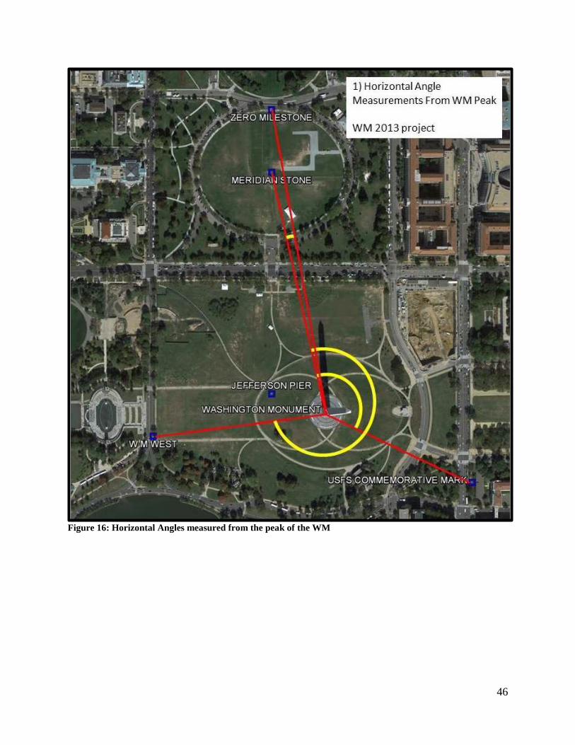
46
Figure 16: Horizontal Angles measured from the peak of the WM

47
Figure 17: Horizontal Angles measured from ground control around the WM
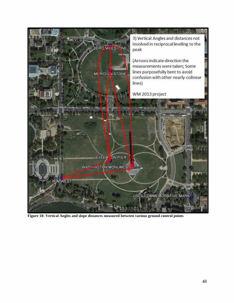
48
Figure 18: Vertical Angles and slope distances measured between various ground control points

49
Figure 19: Reciprocal Vertical Angles and Distances (RVAD) measured to and from the peak of the WM
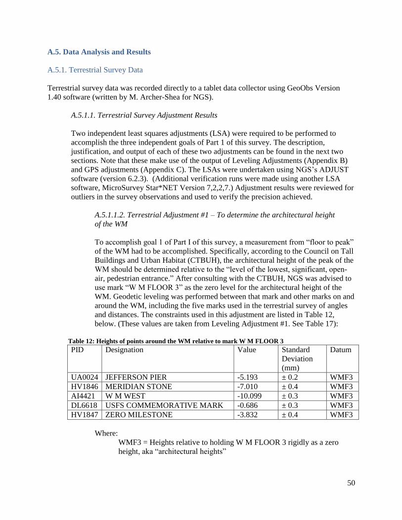
50
A.5. Data Analysis and Results
A.5.1. Terrestrial Survey Data
Terrestrial survey data was recorded directly to a tablet data collector using GeoObs Version
1.40 software (written by M. Archer-Shea for NGS).
A.5.1.1. Terrestrial Survey Adjustment Results
Two independent least squares adjustments (LSA) were required to be performed to
accomplish the three independent goals of Part 1 of this survey. The description,
justification, and output of each of these two adjustments can be found in the next two
sections. Note that these make use of the output of Leveling Adjustments (Appendix B)
and GPS adjustments (Appendix C). The LSAs were undertaken using NGS’s ADJUST
software (version 6.2.3). (Additional verification runs were made using another LSA
software, MicroSurvey Star*NET Version 7,2,2,7.) Adjustment results were reviewed for
outliers in the survey observations and used to verify the precision achieved.
A.5.1.1.2. Terrestrial Adjustment #1 – To determine the architectural height
of the WM
To accomplish goal 1 of Part I of this survey, a measurement from “floor to peak”
of the WM had to be accomplished. Specifically, according to the Council on Tall
Buildings and Urban Habitat (CTBUH), the architectural height of the peak of the
WM should be determined relative to the “level of the lowest, significant, open-
air, pedestrian entrance.” After consulting with the CTBUH, NGS was advised to
use mark “W M FLOOR 3” as the zero level for the architectural height of the
WM. Geodetic leveling was performed between that mark and other marks on and
around the WM, including the five marks used in the terrestrial survey of angles
and distances. The constraints used in this adjustment are listed in Table 12,
below. (These values are taken from Leveling Adjustment #1. See Table 17):
Table 12: Heights of points around the WM relative to mark W M FLOOR 3
PID Designation Value Standard
Deviation
(mm)
Datum
UA0024 JEFFERSON PIER -5.193 ± 0.2 WMF3
HV1846 MERIDIAN STONE -7.010 ± 0.4 WMF3
AI4421 W M WEST -10.099 ± 0.3 WMF3
DL6618 USFS COMMEMORATIVE MARK -0.686 ± 0.3 WMF3
HV1847 ZERO MILESTONE -3.832 ± 0.4 WMF3
Where:
WMF3 = Heights relative to holding W M FLOOR 3 rigidly as a zero
height, aka “architectural heights”

51
Table 13 contains the output of Terrestrial Adjustment #1, including the height of
the peak in the floor-centric system, or the “architectural height” of the
Washington Monument.
Table 13: Output of Terrestrial Adjustment #1 showing the architectural height of the Washington
Monument and its standard deviation
PID Designation Value Standard
Deviation
(mm)
Datum
HV4442 WASHINGTON MONUMENT 169.046 ± 1.0 WMF3
A.5.1.1.1. Terrestrial Adjustment #2 – To determine the latitude, longitude, and
ellipsoid height of the WM and the USFS Commemorative Mark, as well as the
orthometric height of the WM in the National Spatial Reference System.
For both goals 2 and 3 of Part I of this survey, a single LSA suffices,
holding as fixed the NSRS coordinates of certain points around the National
Mall, and solving for the coordinates of the peak of the WM and USFS
COMMEMORATIVE MARK. Attempts to solve for latitude and longitude of
USFS COMMEMORATIVE MARK were made using GPS (See Appendix C),
but were ultimately abandoned as less accurate than when determined using
terrestrial techniques.
This LSA does not provide information about the architectural height of the
monument, only the location of the peak in the national coordinate frame, known
as the National Spatial Reference System.
The coordinates held fixed in this adjustment are listed in Table 14 below. The
NAVD 88 orthometric heights and standard deviations were newly computed
based on Leveling Adjustment #1 (see Appendix B). The NAD 83(2011) epoch
2010.00 coordinates and standard deviations were taken from the NGS Integrated
Database. However, it was found that the latitude of ZERO MILESTONE fit less
well in the adjustment than its formal a-priori error estimate would indicate. This
latitude was therefore more loosely constrained for this adjustment than other
constrained points.

52
Table 14: Stochastic control (input) to Terrestrial Adjustment #2
PID Designation Value Standard
Deviation
(mm)
Datum Source
UA0024 JEFFERSON PIER N 38° 53’ 23.29439”
W 77° 02’ 11.56187”
7.022 m
± 1.4
± 1.1
± 0.3
83(11)
83(11)
88
IDB
IDB
LA2
HV1846 MERIDIAN STONE N 38° 53’ 38.16944”
W 77° 02’ 11.55811”
5.204 m
± 2.5
± 1.9
± 0.1
83(11)
83(11)
88
IDB
IDB
LA2
AI4421 W M WEST N 38° 53’ 20.44248”
W 77° 02’ 21.79815”
2.116 m
± 2.9
± 2.2
± 0.1
83(11)
83(11)
88
IDB
IDB
LA2
DL6618 USFS
COMMEMORATIVE
MARK
11.529 m ± 0.7 88 LA2
HV1847 ZERO MILESTONE N 38° 53’ 42.38736”
W 77° 02’ 11.57299”
8.382 m
(free)
± 4.6
± 0.1
83(11)
83(11)
88
IDB
IDB
LA2
Where:
83(11) = NAD 83(2011) epoch 2010.00
88 = NAVD 88
IDB = NGS Integrated Database
LA2 = Leveling Adjustment #2 (see Appendix B)
Table 15 contains the output of Terrestrial Adjustment #1, including the latitude,
longitude, and orthometric heights of the peak of the WM in the NSRS:
Table 15: Output coordinates and standard deviations from Terrestrial Adjustment #2
PID Designation Value Standard
Deviation
(mm)
Datum
HV4442 WASHINGTON
MONUMENT
N 38° 53’ 22.08257”
W 77° 02’ 06.86428”
h = 149.172 m
H = 181.261 m
± 2.0
± 1.0
± 1.0
± 1.0
83(11)
83(11)
83(11)
88
DL6618 USFS
COMMEMORATIVE
MARK
N 38° 53’ 17.34662”
W 77° 01’ 54.23701”
h = -20.568 m
± 3.0
± 2.0
± 1.0
83(11)
83(11)
83(11)
A.6. Conclusion
The terrestrial survey results establish a baseline against which future field measurements could
be used to assess geospatial stability of the monument over time. Leveling adjustments provided
critical information required to arrive at these final values in the terrestrial adjustments. GPS
adjustments served as a blunder check, but did not contribute to the final values.
53
A.7. References
A.7.1. Name of person responsible for observations
Mark Eckl
Chief, Observation and Analysis Division
National Geodetic Survey
A.7.2. Name of person(s) responsible for analysis
Kendall Fancher
National Geodetic Survey
15351 Office Drive
Woodford, VA 22580
Phone – (540) 373-1243
Email – [email protected]
Steven Breidenbach
National Geodetic Survey
15351 Office Drive
Woodford, VA 22580
Phone – (540) 373-1243
Email – [email protected]
A.7.3. Location of observation data and results archive
National Geodetic Survey
Instrumentation & Methodologies Branch
15351 Office Drive
Woodford, VA 22580
(540) 373-1243
A digital copy of all observation files, analysis and results is stored on the NGS server
“Brunswick,” under the shared directory “Washington Monument 2013.”

54
Appendix B – Leveling Survey of the Washington Monument
This appendix covers the details of the second of three survey types conducted at the Washington
Monument during the 2013–2014 survey. The three survey types, and the appendices covering
their full details are:
Terrestrial Survey – (November 5 and 6, 2013) – Appendix A
Leveling Survey – (April 8, 9, 10, 14, and 21, 2014) – Appendix B
GPS Survey – (November 1 to 8, 2013) – Appendix C
The specific term “leveling survey” is used to mean the measurement of orthometric height
differences between various points around the WM.
B.1. Introduction
On April 8, 9, 10, 14, and 21 of 2014, NGS conducted geodetic leveling as part of the greater
2013–2014 survey of the Washington Monument. With pavers surrounding the monument
removed, NGS was provided a rare opportunity to access historic bench marks that otherwise
were inaccessible. Further, while the monument remained closed, there was an opportunity to
survey directly to the floor of the monument without disrupting tourist traffic. All field
procedures in this project conformed to FGCS standards of First order, Class II (Federal
Geodetic Control Committee 1984).
This report documents the instrumentation, procedures, data analysis, and results associated with
the leveling observations conducted during this survey.
B.2. Instrumentation
B.2.1. Levels and Rods
B.2.1.1. Description
Two different levels were used during this survey, listed below:
Leica DNA03 Digital Barcode Level (serial numbers: 333426 and 334271)
Height precision, 0.00001 m
Height accuracy, 0.0003 m per km, double-run
Distance measurement accuracy, = 500 ppm.
Three different sets of level rods were used during this survey, listed below.
Leica three-meter invar digital barcode rods (04/08/14 and 04/09/1), Serial Numbers
# 26613 and 26614.
Lecia three-meter invar digital barcode rods (04/10/14 and 04/14/2014), used with Leica
DNA03 Serial Numbers# 334271: 27226 and 27227.
55
Leica two-meter invar digital barcode rods (04/22/14): Serial Numbers# 30579 and
30721.
B.2.1.2. Calibrations
B.2.1.2.1. Level Calibrations
The Leica DNA03 digital barcode level, Serial Number# 333426 was calibrated
according to factory specifications by Leica Geosystems Inc., Technical Service,
from Duluth, GA, on 05/13/2013.
B.2.1.2.2. Rod Calibrations
Three-meter rods Serial Numbers# 26613 and 26614 were calibrated in October
1994 at the Technical University of Munich.
Three-meter rods Serial Numbers# 27226 and 27227 were calibrated in
September 1995 at the Technical University of Munich.
Two-meter rods Serial Numbers# 30579 and 30721 were calibrated in August
2006 by the Université de Laval, Québec, CA.
B.2.1.3. Auxiliary Equipment
Cast iron/steel turning points: both “turtles” and “pins”
Rubber-faced mallets to drive and recover pins
Leica backup recording sheets (multiple, one per setup)
Matching 2.0 cm magnetic plugs
B.2.2. Tripods
Wild TYP-2 tripods with vented and shielded temperature probes at 0.3 m and 1.3 m above
ground were used to mount the levels at each setup.
B.3. Measurement Setup
B.3.1. Ground Network
B.3.1.1. Ground Network Mark Listing
All marks that were part of the 2014 Leveling around the Washington Monument are
listed in Table 16, below. See also Appendix E for more identifying information for
each mark.
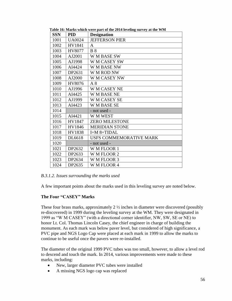
56
Table 16: Marks which were part of the 2014 leveling survey at the WM
SSN PID Designation
1001 UA0024 JEFFERSON PIER
1002 HV1841 A
1003 HV8077 B 8
1004 AJ2001 W M BASE SW
1005 AJ1998 W M CASEY SW
1006 AI4424 W M BASE NW
1007 DP2631 W M ROD NW
1008 AJ2000 W M CASEY NW
1009 HV8076 A 8
1010 AJ1996 W M CASEY NE
1011 AI4425 W M BASE NE
1012 AJ1999 W M CASEY SE
1013 AI4423 W M BASE SE
1014 - not used -
1015 AI4421 W M WEST
1016 HV1847 ZERO MILESTONE
1017 HV1846 MERIDIAN STONE
1018 HV1838 I=M 8=TIDAL
1019 DL6618 USFS COMMEMORATIVE MARK
1020 - not used -
1021 DP2632 W M FLOOR 1
1022 DP2633 W M FLOOR 2
1023 DP2634 W M FLOOR 3
1024 DP2635 W M FLOOR 4
B.3.1.2. Issues surrounding the marks used
A few important points about the marks used in this leveling survey are noted below.
The Four “CASEY” Marks
These four brass marks, approximately 2 ½ inches in diameter were discovered (possibly
re-discovered) in 1999 during the leveling survey at the WM. They were designated in
1999 as “W M CASEY” (with a directional corner identifier, NW, SW, SE or NE) to
honor Lt. Col. Thomas Lincoln Casey, the chief engineer in charge of building the
monument. As each mark was below paver level, but considered of high significance, a
PVC pipe and NGS Logo Cap were placed at each mark in 1999 to allow the marks to
continue to be useful once the pavers were re-installed.
The diameter of the original 1999 PVC tubes was too small, however, to allow a level rod
to descend and touch the mark. In 2014, various improvements were made to these
marks, including:
New, larger diameter PVC tubes were installed
A missing NGS logo cap was replaced
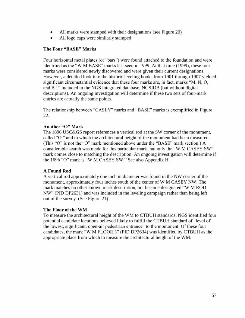
57
All marks were stamped with their designations (see Figure 20)
All logo caps were similarly stamped
The Four “BASE” Marks
Four horizontal metal plates (or “bars”) were found attached to the foundation and were
identified as the “W M BASE” marks last seen in 1999. At that time (1999), these four
marks were considered newly discovered and were given their current designations.
However, a detailed look into the historic leveling books from 1901 through 1907 yielded
significant circumstantial evidence that these four marks are, in fact, marks “M, N, O,
and B 1” included in the NGS integrated database, NGSIDB (but without digital
descriptions). An ongoing investigation will determine if these two sets of four-mark
entries are actually the same points.
The relationship between “CASEY” marks and “BASE” marks is exemplified in Figure
22.
Another “O” Mark
The 1896 USC&GS report references a vertical rod at the SW corner of the monument,
called “O,” and to which the architectural height of the monument had been measured.
(This “O” is not the “O” mark mentioned above under the “BASE” mark section.) A
considerable search was made for this particular mark, but only the “W M CASEY SW”
mark comes close to matching the description. An ongoing investigation will determine if
the 1896 “O” mark is “W M CASEY SW.” See also Appendix H.
A Found Rod
A vertical rod approximately one inch in diameter was found in the NW corner of the
monument, approximately four inches south of the center of W M CASEY NW. The
mark matches no other known mark description, but became designated “W M ROD
NW” (PID DP2631) and was included in the leveling campaign rather than being left
out of the survey. (See Figure 21)
The Floor of the WM
To measure the architectural height of the WM to CTBUH standards, NGS identified four
potential candidate locations believed likely to fulfill the CTBUH standard of “level of
the lowest, significant, open-air pedestrian entrance” to the monument. Of these four
candidates, the mark “W M FLOOR 3” (PID DP2634) was identified by CTBUH as the
appropriate place from which to measure the architectural height of the WM.
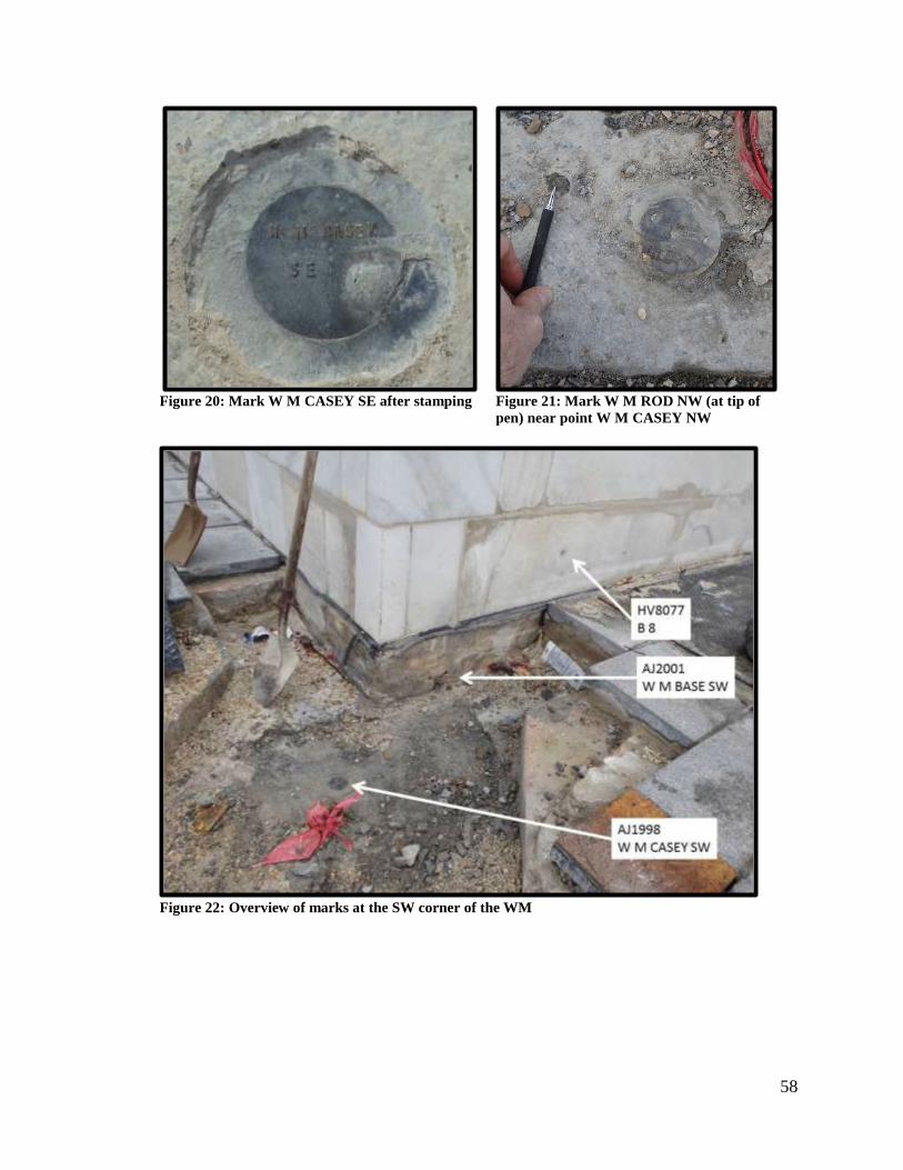
58
Figure 20: Mark W M CASEY SE after stamping
Figure 21: Mark W M ROD NW (at tip of
pen) near point W M CASEY NW
Figure 22: Overview of marks at the SW corner of the WM

59
B.4. Observations
All geodetic leveling performed as part of this project was assigned NGS identifier “Level Line
L28141.” This Level Line consisted of four loops, each containing between five and eight
sections, where each section was double-run to First order, Class II standards. Each loop is
described below. Much of this work was done on specific dates to accommodate the crews who
were re-assembling pavers and pouring concrete.
Turning pins were used for turns in the grassy areas around the monument and mall. When
leveling in the paver area of the monument, turtles were used for turns, and the tripod was set up
directly on pavers (avoiding the protective rubber mats covering much of the paved area).
B.4.1. Loop 1 – “West Side” – April 8, 2014
Nine marks, making up a loop of nine sections were leveled on April 8, 2014. These marks were
mostly on the NW and SW corners of the monument, as the East side marks were still
inaccessible with the last remnants of scaffolding still in place on that side. The nine marks, in
clockwise order around the loop were:
SSN PID Designation
1002 HV1841 A
1001 UA0024 JEFFERSON PIER
1009 HV8076 A 8
1008 AJ2000 W M CASEY NW
1007 DP2631 W M ROD NW
1006 AI4424 W M BASE NW
1005 AJ1998 W M CASEY SW
1004 AJ2001 W M BASE SW
1003 HV8077 B 8
B.4.2. Loop 2 – “East Side” – April 9, 2014
Eight marks, making up a loop of eight sections were leveled on April 9, 2014. These marks
were mostly on the NE and SE corners of the monument, as the last remnants of scaffolding had
been removed on that side. However, marks overlapping with the “West Side” loop were added
to gain redundancy. The eight marks, in clockwise order around the loop were:
SSN PID Designation
1003 HV8077 B 8
1005 AJ1998 W M CASEY SW
1008 AJ2000 W M CASEY NW
1009 HV8076 A 8
1010 AJ1996 W M CASEY NE
1011 AI4425 W M BASE NE
1012 AJ1999 W M CASEY SE
1013 AI4423 W M BASE SE

60
B.4.3. Loop 3 – “Around the Mall” – April 10 and 14, 2014
Eight marks, making up a loop of eight sections were leveled on April 10 and 14, 2014. The size
of this loop necessitated it being run in clockwise direction on the 10 and counterclockwise on
the 14. The marks chosen for this loop were explicitly chosen as ones used in the Terrestrial
Survey (see Appendix A), with overlapping points from the West Side and East Side loops, for
redundancy. The eight marks, in clockwise order around the loop were:
SSN PID Designation
1003 HV8077 B 8
1002 HV1841 A
1001 UA0024 JEFFERSON PIER
1015 AI4421 W M WEST
1016 HV1847 ZERO MILESTONE
1017 HV1846 MERIDIAN STONE
1018 HV1838 I=M 8=TIDAL
1019 DL6618 USFS COMMEMORATIVE MARK
B.4.4. Loop 4 – “Connecting to the Floor” – April 22, 2014
Six marks, making up a loop of six sections, were leveled on April 22, 2014. Due to ongoing
discussion with the CTBUH regarding which “level” the architectural height of the WM should
be referred, four likely candidates were chosen. These four are described and justified in
Appendix E. The six marks, in clockwise order around the loop were:
SSN PID Designation
1003 HV8077 B 8
1009 HV8076 A 8
1024 DP2635 W M FLOOR 4
1023 DP2634 W M FLOOR 3
1022 DP2633 W M FLOOR 2
1021 DP2632 W M FLOOR 1

61
Figure 23: Level Loop 1 (West Side) conducted April 8, 2014
Figure 24: Level Loop 2 (East Side) conducted April 9, 2014
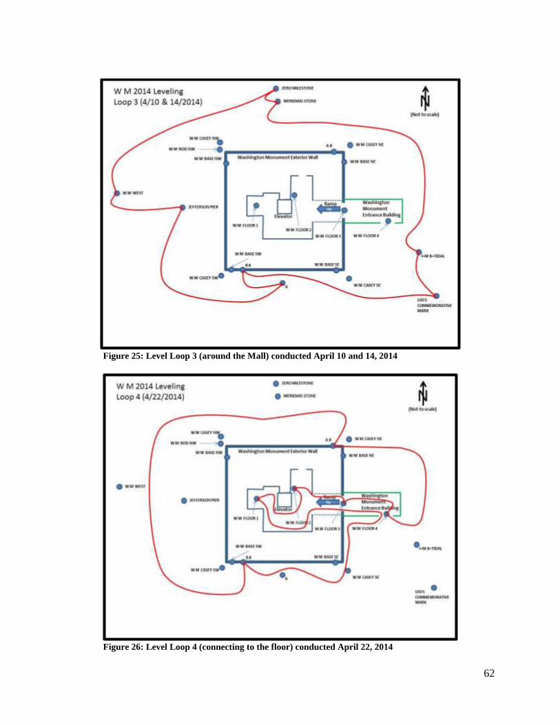
62
Figure 25: Level Loop 3 (around the Mall) conducted April 10 and 14, 2014
Figure 26: Level Loop 4 (connecting to the floor) conducted April 22, 2014
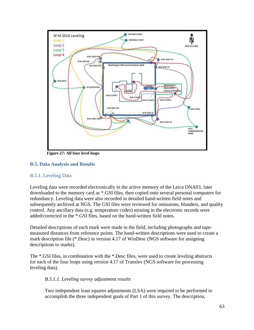
63
Figure 27: All four level loops
B.5. Data Analysis and Results
B.5.1. Leveling Data
Leveling data were recorded electronically in the active memory of the Leica DNA03, later
downloaded to the memory card as *.GSI files, then copied onto several personal computers for
redundancy. Leveling data were also recorded in detailed hand-written field notes and
subsequently archived at NGS. The GSI files were reviewed for omissions, blunders, and quality
control. Any ancillary data (e.g. temperature codes) missing in the electronic records were
added/corrected in the *.GSI files, based on the hand-written field notes.
Detailed descriptions of each mark were made in the field, including photographs and tape-
measured distances from reference points. The hand-written descriptions were used to create a
mark description file (*.Desc) in version 4.17 of WinDesc (NGS software for assigning
descriptions to marks).
The *.GSI files, in combination with the *.Desc files, were used to create leveling abstracts
for each of the four loops using version 4.17 of Translev (NGS software for processing
leveling data).
B.5.1.1. Leveling survey adjustment results
Two independent least squares adjustments (LSA) were required to be performed to
accomplish the three independent goals of Part 1 of this survey. The description,
64
justification, and output of each of these two adjustments can be found in the next two
sections. Note that both of these Leveling Adjustments serve as the basis for later
Terrestrial Survey Adjustments (see Appendix A). The LSAs were undertaken using
software ASTA.
B.5.1.1.1. Leveling Adjustment #1 – To determine the Floor-centric
(“architectural”) heights of all leveled marks in the WM 2013 project.
To accomplish Goal 1 of Part I of this survey, a measurement from “floor to
peak” of the WM was required. Specifically, according to the Council on Tall
Buildings and Urban Habitat (CTBUH), the architectural height of the peak of the
WM should be determined relative to the “level of the lowest, significant, open-
air, pedestrian entrance.” After consulting with the CTBUH, NGS was advised to
use “W M FLOOR 3” as the zero level for the architectural height of the WM6.
Geodetic leveling was performed between that mark and other marks on and
around the WM, including the five marks used in the terrestrial survey of angles
and distances (RVAD/HA survey).
To provide input control to Terrestrial Survey adjustment #1, this first leveling
adjustment was performed, where the only fixed constraint was that the
architectural height of mark “W M FLOOR 3” was held equal to 0.000m
with a standard deviation of 0.0 mm.
Table 17 contains the output of Leveling Adjustment #1.
6 The CTBUH has existed since 1969, but it is not clear whether or not NGS consulted CTBUH in 1999. Most
evidence indicates that NGS made an internal decision on how to calculate the architectural height of the WM. The
choice made seems to have been to refer the height to “the CASEY marks” in an attempt to replicate what was
assumed to be the same choice made in 1885 (Dave Doyle, 2014, Personal Communication). See Appendix H.
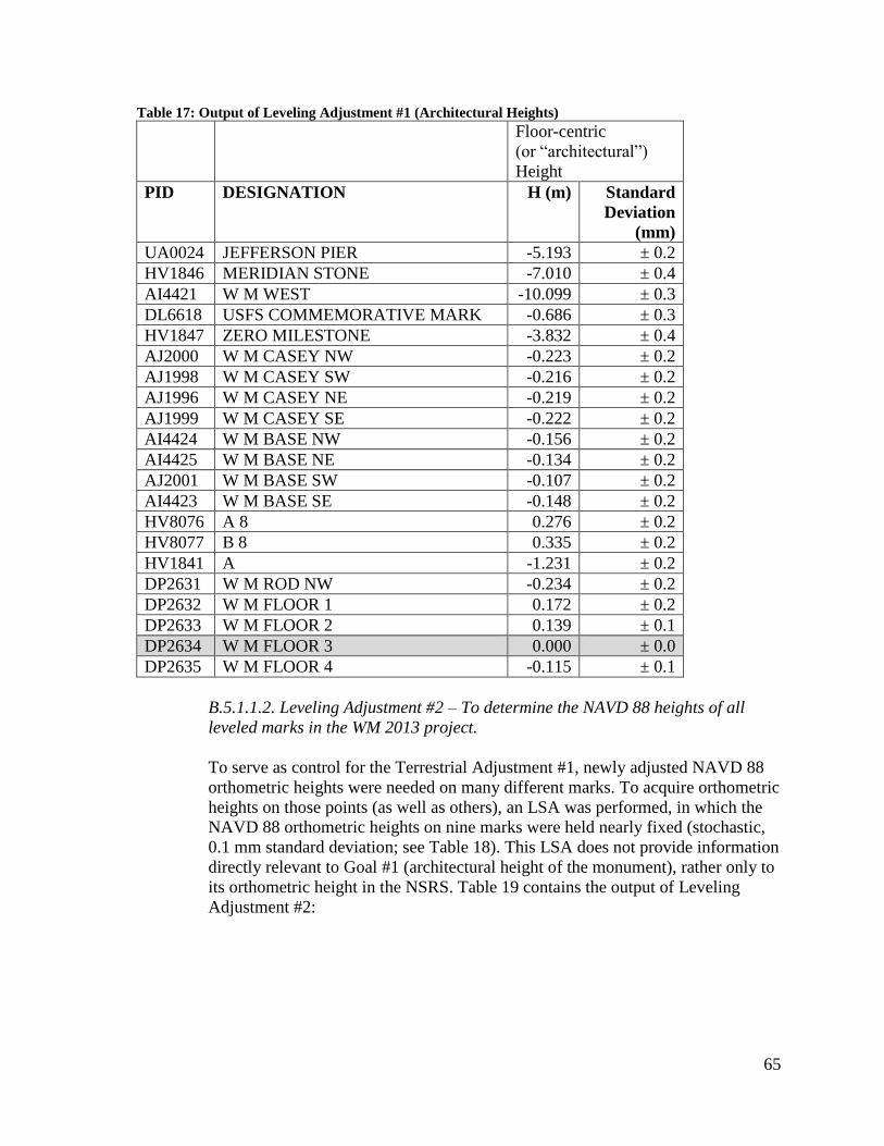
65
Table 17: Output of Leveling Adjustment #1 (Architectural Heights)
Floor-centric
(or “architectural”)
Height
PID DESIGNATION H (m) Standard
Deviation
(mm)
UA0024 JEFFERSON PIER -5.193 ± 0.2
HV1846 MERIDIAN STONE -7.010 ± 0.4
AI4421 W M WEST -10.099 ± 0.3
DL6618 USFS COMMEMORATIVE MARK -0.686 ± 0.3
HV1847 ZERO MILESTONE -3.832 ± 0.4
AJ2000 W M CASEY NW -0.223 ± 0.2
AJ1998 W M CASEY SW -0.216 ± 0.2
AJ1996 W M CASEY NE -0.219 ± 0.2
AJ1999 W M CASEY SE -0.222 ± 0.2
AI4424 W M BASE NW -0.156 ± 0.2
AI4425 W M BASE NE -0.134 ± 0.2
AJ2001 W M BASE SW -0.107 ± 0.2
AI4423 W M BASE SE -0.148 ± 0.2
HV8076 A 8 0.276 ± 0.2
HV8077 B 8 0.335 ± 0.2
HV1841 A -1.231 ± 0.2
DP2631 W M ROD NW -0.234 ± 0.2
DP2632 W M FLOOR 1 0.172 ± 0.2
DP2633 W M FLOOR 2 0.139 ± 0.1
DP2634 W M FLOOR 3 0.000 ± 0.0
DP2635 W M FLOOR 4 -0.115 ± 0.1
B.5.1.1.2. Leveling Adjustment #2 – To determine the NAVD 88 heights of all
leveled marks in the WM 2013 project.
To serve as control for the Terrestrial Adjustment #1, newly adjusted NAVD 88
orthometric heights were needed on many different marks. To acquire orthometric
heights on those points (as well as others), an LSA was performed, in which the
NAVD 88 orthometric heights on nine marks were held nearly fixed (stochastic,
0.1 mm standard deviation; see Table 18). This LSA does not provide information
directly relevant to Goal #1 (architectural height of the monument), rather only to
its orthometric height in the NSRS. Table 19 contains the output of Leveling
Adjustment #2:

66
Table 18: Stochastic Constraints (input) to Leveling Adjustment #2
NAVD 88 Ortho Heights
PID Designation H (m) Standard
Deviation (mm)
HV1846 MERIDIAN STONE 5.204 ± 0.1
AI4421 W M WEST 2.116 ± 0.1
HV1847 ZERO MILESTONE 8.382 ± 0.1
AJ1998 W M CASEY SW 11.999 ± 0.1
AJ1999 W M CASEY SE 11.994 ± 0.1
AJ2000 W M CASEY NW 11.993 ± 0.1
AJ1996 W M CASEY NE 11.997 ± 0.1
HV8077 B 8 12.550 ± 0.1
HV8076 A 8 12.492 ± 0.1
Table 19: Output of Leveling Adjustment #2 (NAVD 88 heights)
NAVD 88 Ortho Heights
PID Designation H (m) Standard
Deviation (mm)
HV1846 MERIDIAN STONE 5.204 ± 0.1
AI4421 W M WEST 2.116 ± 0.1
HV1847 ZERO MILESTONE 8.382 ± 0.1
AJ1998 W M CASEY SW 11.999 ± 0.1
AJ1999 W M CASEY SE 11.994 ± 0.1
AJ2000 W M CASEY NW 11.993 ± 0.1
AJ1996 W M CASEY NE 11.997 ± 0.1
HV8077 B 8 12.550 ± 0.1
HV8076 A 8 12.492 ± 0.1
UA0024 JEFFERSON PIER 7.022 ± 0.3
DL6618 USFS COMMEMORATIVE MARK 11.529 ± 0.7
HV1841 A 10.984 ± 0.3
AI4424 W M BASE NW 12.059 ± 0.3
AI4425 W M BASE NE 12.082 ± 0.3
AJ2001 W M BASE SW 12.108 ± 0.3
AI4423 W M BASE SE 12.068 ± 0.3
DP2631 W M ROD NW 11.982 ± 0.3
DP2632 W M FLOOR 1 12.387 ± 0.4
DP2633 W M FLOOR 2 12.354 ± 0.4
DP2634 W M FLOOR 3 12.216 ± 0.5
DP2635 W M FLOOR 4 12.101 ± 0.4
HV1838 I=M 8=TIDAL 6.018 ± 0.7

67
B.6. Conclusion
The leveling survey results provide a critical connection amongst marks near the WM, both in
the official vertical datum of the United States (NAVD 88) and in a “floor centric” system which
allows for adherence to the CTBUH standards in determining building heights. The connection
of both these systems to “the CASEY marks” also allows for a comparison with the 1999 survey.
B.7. References
B.7.1. Name of persons responsible for observations
Philippe Hensel
Observation and Analysis Division
National Geodetic Survey
Phone – (301) 713-3208 extension 137
Email – [email protected]
Steven Breidenbach
Instrumentation and Methodologies Branch
National Geodetic Survey
15351 Office Drive
Woodford, VA 22580
Phone – (540) 373-1243
Email – [email protected]
Eric Duvall
Observation and Analysis Division
National Geodetic Survey
Phone – (301) 713-3215 x141
Email – [email protected]
B.7.2. Name of person responsible for analysis
Ajit Singh
Observation and Analysis Division
National Geodetic Survey
Phone – (301) 713-3182 extension 109
Email – [email protected]
B.7.3. Location of observation data and results archive
National Geodetic Survey
Silver Spring, MD 20910
A digital copy of all observation files, analyses, and results is stored on the NGS server,
“Brunswick,” under the shared directory “Washington Monument 2013.”
68
Appendix C – GPS Survey of the Washington Monument
This appendix covers the details of the third of three survey types conducted at the Washington
Monument during the 2013–2014 survey. The three survey types and the appendices covering
their full details are:
Terrestrial Survey – (November 5 and 6, 2013) – Appendix A
Leveling Survey – (April 8, 9, 10, 14, and 21, 2014) – Appendix B
GPS Survey – (November 1 to 8, 2013) – Appendix C
The term “GPS survey” is specifically used to indicate the collection of GPS signals in a
geodetic quality receiver mounted over a survey mark. Three types of data were collected as part
of this survey:
a. Data from the CORS network, used as the primary access to the National Spatial
Reference System
b. Data from a GPS receiver mounted over the Washington Monument peak for multiple
continuous days
c. Data from a “GPS campaign,” with multiple receivers simultaneously deployed over
marks on and around the Washington Monument
This appendix is provided primarily for informational purposes. The GPS survey itself was
ultimately less accurate than the terrestrial survey and was not used in the final determination of
unknown values in this report.
C.1. Introduction
From November 1 through November 8, 2013, NGS conducted a GPS survey as part of the
greater 2013–2014 survey of the Washington Monument. Scaffolding, installed for renovation
purposes, afforded a rare opportunity to directly occupy the Washington Monument peak during
a portion of the GPS survey.
This appendix documents the instrumentation, procedures, data analysis, and results associated
with the GPS observations conducted during this survey.
C.2. Instrumentation
C.2.1. GPS Receivers and Antennae
C.2.1.1. Description
Eight GPS receivers were used throughout this survey, listed below:
Trimble NETR5 (serial numbers: 4624K01584, 4619K01307, 4624K01583,
4624K01615, 4624K01648, 4624K01634, 4624K01590, 4624K01631)
Eight GPS antennae were used throughout this survey, listed below:
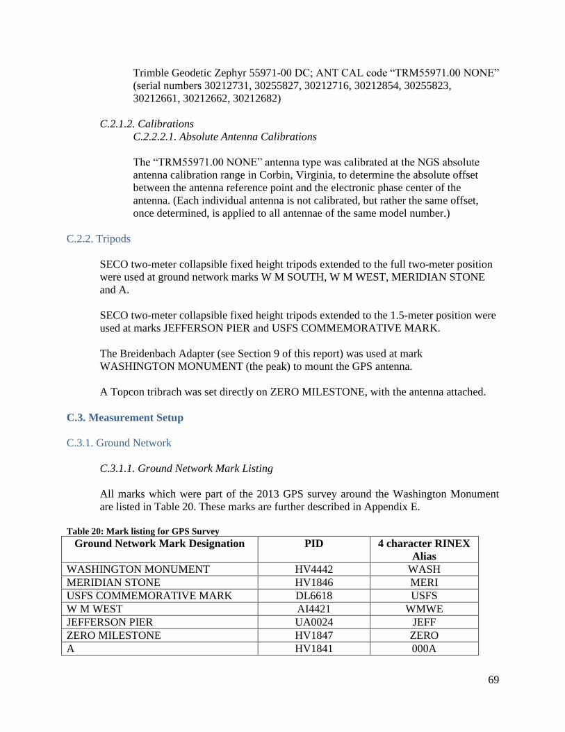
69
Trimble Geodetic Zephyr 55971-00 DC; ANT CAL code “TRM55971.00 NONE”
(serial numbers 30212731, 30255827, 30212716, 30212854, 30255823,
30212661, 30212662, 30212682)
C.2.1.2. Calibrations
C.2.2.2.1. Absolute Antenna Calibrations
The “TRM55971.00 NONE” antenna type was calibrated at the NGS absolute
antenna calibration range in Corbin, Virginia, to determine the absolute offset
between the antenna reference point and the electronic phase center of the
antenna. (Each individual antenna is not calibrated, but rather the same offset,
once determined, is applied to all antennae of the same model number.)
C.2.2. Tripods
SECO two-meter collapsible fixed height tripods extended to the full two-meter position
were used at ground network marks W M SOUTH, W M WEST, MERIDIAN STONE
and A.
SECO two-meter collapsible fixed height tripods extended to the 1.5-meter position were
used at marks JEFFERSON PIER and USFS COMMEMORATIVE MARK.
The Breidenbach Adapter (see Section 9 of this report) was used at mark
WASHINGTON MONUMENT (the peak) to mount the GPS antenna.
A Topcon tribrach was set directly on ZERO MILESTONE, with the antenna attached.
C.3. Measurement Setup
C.3.1. Ground Network
C.3.1.1. Ground Network Mark Listing
All marks which were part of the 2013 GPS survey around the Washington Monument
are listed in Table 20. These marks are further described in Appendix E.
Table 20: Mark listing for GPS Survey
Ground Network Mark Designation PID 4 character RINEX
Alias
WASHINGTON MONUMENT HV4442 WASH
MERIDIAN STONE HV1846 MERI
USFS COMMEMORATIVE MARK DL6618 USFS
W M WEST AI4421 WMWE
JEFFERSON PIER UA0024 JEFF
ZERO MILESTONE HV1847 ZERO
A HV1841 000A

70
W M EAST AI4420 WMEA
W M SOUTH AI4422 WMSO
C.4. Observations
C.4.1. CORS
The CORS network was operational during the entire GPS survey. The choice to use a particular
CORS during the processing of the GPS survey was made months after the fact and will be
discussed later in this appendix.
C.4.2. Continuous GPS at the Peak
To check how well it fit, in November 1, 2013, the newly-built adapter was taken to the peak of
the WM. The fit was perfect, and a GPS receiver (Trimble NetR5 S/N 4624K01584) and antenna
(Trimble Geodetic zephyr 55971-00 DC, S/N 30212731; ANTCAL = TRM55971.00 NONE)
were taken to the peak.
The antenna was mounted on the adapter (HI = 0.205 meters above the rounded peak; see Figure
28), and a cable leading to the receiver was inserted into the monument through a hole
in the external wall, just below the pyramidion at the 500-foot floor level (see Figure 29). Data
collection began at 17:00:15 UTC on November 1, 2013 and continued nonstop through
14:33:20 on November 5, 2013 running at a rate of five seconds.
This continuous collection was briefly interrupted on November 5, 2013 for the first day of the
Terrestrial Survey (see Appendix A). Following completion of work that day, the GPS was re-
installed and ran continuously between 20:03:00 on November 5, 2013, through 13:28:00 on
November 6, 2013.
A second interruption occurred on November 6, 2013 from 13:28:00, through 18:51:00, to allow
for the completion of the Terrestrial Survey (see Appendix A). The receiver was then re-installed
and re-initialized, and it remained on overnight and through the following day to correspond with
the Campaign GPS survey (see next section) until it was turned off, dismantled, and removed at
19:02:00 on November 7, 2013.

71
Figure 28: GPS antenna mounted on adapter
at WM peak
Figure 29: GPS cable coming inside WM through
hole in wall
C.4.3. Campaign GPS Survey
A “campaign” GPS survey consists of multiple receivers deployed at the same time to reduce or
eliminate common-mode errors in data processing. On November 7, 2013, a campaign GPS
survey was executed at a variety of passive control marks surrounding the WM. Points were
chosen in the following priority:
a. Highest: A point used in the terrestrial survey (see Appendix A)
b. Next highest: A point used in the 1999 GPS campaign survey
c. Lowest: A point participating in neither “a” nor “b,” (above)
Using these criteria, Table 21 shows points occupied as part of the GPS campaign.

72
Table 21: Participating marks in the 2013 GPS campaign
DESIGNATION PID Terrestrial
Survey
1999 GPS
Survey
Neither
JEFFERSON PIER UA0024
MERIDIAN STONE HV1846
ZERO MILESTONE HV1847
USFS COMMEMORATIVE MARK DL6618
W M WEST AI4421
A HV1841
W M EAST AI4420
W M SOUTH AI4422
A map of these points is provided in Figure 30.
Figure 30: All passive geodetic control points participating in the GPS survey
Note that W M EAST was not intended to be part of the GPS campaign, however a receiver was
briefly (incorrectly) set at the location intended for USFS COMMEMORATIVE MARK. After
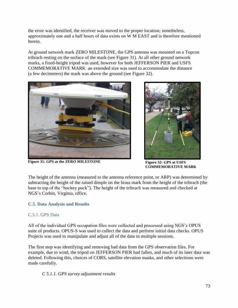
73
the error was identified, the receiver was moved to the proper location; nonetheless,
approximately one and a half hours of data exists on W M EAST and is therefore mentioned
herein.
At ground network mark ZERO MILESTONE, the GPS antenna was mounted on a Topcon
tribrach resting on the surface of the mark (see Figure 31). At all other ground network
marks, a fixed-height tripod was used, however for both JEFFERSON PIER and USFS
COMMEMORATIVE MARK an extended size was used to accommodate the distance
(a few decimeters) the mark was above the ground (see Figure 32).
Figure 31: GPS at the ZERO MILESTONE
Figure 32: GPS at USFS
COMMEMORATIVE MARK
The height of the antenna (measured to the antenna reference point, or ARP) was determined by
subtracting the height of the raised dimple on the brass mark from the height of the tribrach (the
base to top of the “hockey puck”). The height of the tribrach was measured and checked at
NGS’s Corbin, Virginia, office.
C.5. Data Analysis and Results
C.5.1. GPS Data
All of the individual GPS occupation files were collected and processed using NGS’s OPUS
suite of products. OPUS-S was used to collect the data and perform initial data checks. OPUS
Projects was used to manipulate and adjust all of the data in multiple sessions.
The first step was identifying and removing bad data from the GPS observation files. For
example, due to wind, the tripod on JEFFERSON PIER had fallen, and much of its later data was
deleted. Following this, choices of CORS, satellite elevation masks, and other selections were
made carefully.
C 5.1.1. GPS survey adjustment results

74
Although multiple least squares adjustments were performed on the GPS data, none were
used to in the final reportable values (latitude, longitude, elevation(s), and architectural
height). This was due to a number of factors, described later in this section:
1. The quality of GPS data at WASHINGTON MONUMENT is suspect, due to the
severe multipath environment and signal blocking as a result of the surrounding
metal scaffolding.
2. The as-published (NGS IDB) coordinates of passive control surrounding the WM
provided significantly better fits to the terrestrial measurements to the peak than
did newly-computed coordinates from the GPS campaign. As the reason for this is
not immediately clear, the GPS campaign data was relegated to a secondary
position in computing final coordinates for this survey.
Three least squares adjustments (LSA) of GPS data performed are reported herein7.
The first adjustment was performed in an initial (ultimately abandoned) attempt to
compute an accurate latitude and longitude of mark USFS COMMEMORATIVE MARK
with the intent that it be used as input to Terrestrial Adjustment #2 (see Appendix A).
The second was an attempt to compute the latitude, longitude, and ellipsoid height of the
peak. The third was an attempt to compute the orthometric height of the peak.
C.5.1.1.1. GPS Adjustment #1 – To determine the latitude, longitude, and
ellipsoid height of USFS COMMEMORATIVE MARK.
Multiple attempts were made to compute an NAD 83(2011) epoch 2010.00
coordinate set for USFS COMMEMORATIVE MARK to fit well with the
published coordinate sets of the other marks around the WM. By “fit well” it is
meant that the coordinate set on USFS COMMEMORATIVE MARK would
provide acceptable control to the terrestrial adjustments without being a
statistically significant outlier.
Strangely, the best coordinate set came from ignoring GPS vectors to all other
passive control and allowing three CORS stations to fix the coordinates at USFS
COMMEMORATIVE MARK. The cause for this remains under investigation.
The parameters of this adjustment are listed in Table 22 below. The CORS data
were constrained (±10 mm) to their IGS08 coordinates.
Table 22: Input parameters to GPS Adjustment #1
Elevation Mask 30 degrees
CORS Included GODZ
NRL1
USNO
NETWORK STYLE TRIANGULATED
CONSTRAINTS CORS – 3-D NORMAL
7 Two other adjustments were performed as well. See section 17 of this report.
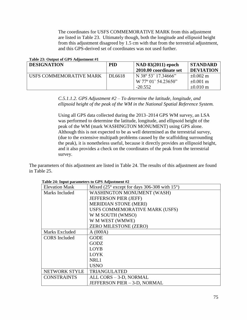
75
The coordinates for USFS COMMEMORATIVE MARK from this adjustment
are listed in Table 23. Ultimately though, both the longitude and ellipsoid height
from this adjustment disagreed by 1.5 cm with that from the terrestrial adjustment,
and this GPS-derived set of coordinates was not used further.
Table 23: Output of GPS Adjustment #1
DESIGNATION PID NAD 83(2011) epoch
2010.00 coordinate set
STANDARD
DEVIATION
USFS COMMEMORATIVE MARK DL6618 N 38º 53’ 17.34666”
W 77º 01’ 54.23650”
-20.552
±0.002 m
±0.001 m
±0.010 m
C.5.1.1.2. GPS Adjustment #2 – To determine the latitude, longitude, and
ellipsoid height of the peak of the WM in the National Spatial Reference System.
Using all GPS data collected during the 2013–2014 GPS WM survey, an LSA
was performed to determine the latitude, longitude, and ellipsoid height of the
peak of the WM (mark WASHINGTON MONUMENT) using GPS alone.
Although this is not expected to be as well determined as the terrestrial survey,
(due to the extensive multipath problems caused by the scaffolding surrounding
the peak), it is nonetheless useful, because it directly provides an ellipsoid height,
and it also provides a check on the coordinates of the peak from the terrestrial
survey.
The parameters of this adjustment are listed in Table 24. The results of this adjustment are found
in Table 25.
Table 24: Input parameters to GPS Adjustment #2
Elevation Mask Mixed (25° except for days 306-308 with 15°)
Marks Included WASHINGTON MONUMENT (WASH)
JEFFERSON PIER (JEFF)
MERIDIAN STONE (MERI)
USFS COMMEMORATIVE MARK (USFS)
W M SOUTH (WMSO)
W M WEST (WMWE)
ZERO MILESTONE (ZERO)
Marks Excluded A (000A)
CORS Included GODE
GODZ
LOYB
LOYK
NRL1
USNO
NETWORK STYLE TRIANGULATED
CONSTRAINTS ALL CORS – 3-D, NORMAL
JEFFERSON PIER – 3-D, NORMAL

76
MERIDIAN STONE – 3-D, NORMAL
USFS – 3-D, NORMAL
W M SOUTH – 3-D, NORMAL
ZERO MILESTONE – 3-D, NORMAL
UNCONSTRAINED WASHINGTON MONUMENT
Table 25: Output of GPS Adjustment #2
DESIGNATION PID NAD 83(2011) epoch
2010.00 coordinate set
STANDARD
DEVIATION
WASHINGTON MONUMENT HV4442 38° 53’ 22.08148”
77° 02’ 06.86115”
149.143 m
± 1.0 mm
± 1.0 mm
± 3.0 mm
These coordinates disagree with the terrestrial adjustments by 3, 9, and 3
centimeters in latitude, longitude and ellipsoid height respectively, and were not
used further.
C.5.1.1.3. GPS Adjustment #3 – To determine the orthometric height of the peak
of the WM in the National Spatial Reference System.
Using all GPS data collected during the 2013–2014 GPS WM survey, an LSA
was performed to determine the orthometric height of the peak of the WM (mark
WASHINGTON MONUMENT) using GPS alone. Although this is not expected
to be as well determined as the terrestrial survey (due to the extensive multipath
problems caused by the scaffolding surrounding the peak), it is nonetheless
useful, because it provides a check on the orthometric height from the terrestrial
survey.
The parameters of this adjustment are listed in Table 26.
Table 26: Input parameters to GPS Adjustment #3
Elevation Mask Mixed (25° except for days 306-308 with 15°)
Marks Included WASHINGTON MONUMENT (WASH)
W M SOUTH (WMSO)
JEFFERSON PIER (JEFF)
MERIDIAN STONE (MERI)
USFS COMMEMORATIVE MARK (USFS)
W M WEST (WMWE)
ZERO MILESTONE (ZERO)
Marks Excluded A (000A)
CORS Included GODE
GODZ
LOYB
LOYK
NRL1
USNO

77
NETWORK STYLE TRIANGULATED
CONSTRAINTS ALL CORS – 3-D, TIGHT
JEFFERSON PIER (JEFF) – VERTICAL ONLY, TIGHT
MERIDIAN STONE (MERI) – VERTICAL ONLY, TIGHT
USFS – VERTICAL ONLY, TIGHT
W M SOUTH (WMSO) – VERTICAL ONLY, TIGHT
ZERO MILESTONE (ZERO) – VERTICAL ONLY, TIGHT
UNCONSTRAINED WASHINGTON MONUMENT
W M SOUTH
GEOID MODEL GEOID12A
The results of this adjustment are found in Table 27.
Table 27: Output of GPS Adjustment #3
DESIGNATION PID NAVD 88 orthometric
height
STANDARD
DEVIATION
WASHINGTON MONUMENT HV4442 181.221 m ± 16.0 mm
This orthometric height disagrees with the terrestrial adjustment by 4 centimeters and was not
used further.
C6. Conclusion
The experiences gained by operating GPS while under scaffolding in 1999 led NGS to presume
that similar difficulties would be experienced again in 2013. This proved to be true. All of the
reportable results for the coordinates of the peak of the WM came from the terrestrial survey
adjustments. However, the GPS survey was worthwhile both to compare against the 1999 results
as well as to provide additional checks on the terrestrial survey, within the limits of the GPS
survey.
C.7. References
C.7.1. Name of person responsible for observations
Eric Duvall
Observation and Analysis Division
National Geodetic Survey
Phone – (301) 713-3215 extension 141
Email – [email protected]
C.7.2. Name of person(s) responsible for analysis
Mark L. Armstrong
Oregon Geodetic Advisor, National Geodetic Survey
4040 Fairview Industrial Drive SE
Building: ODOT

78
Salem,OR 97302
Phone – (503) 986-3775
Email – [email protected]
Dru Smith
Chief Geodesist, National Geodetic Survey
1315 East-West Highway
Silver Spring, MD 20910
Phone – (301) 713-3222 x 144
Email – [email protected]
C.7.3. Location of observation data and results archive
National Geodetic Survey
1315 East-West Highway
Silver Spring, MD 20910
Phone – (301) 713-3222 x 144
A digital copy of all observation files, analysis, and results is stored on the NGS server
“Brunswick” under the shared directory “Washington Monument 2013.”

79
Appendix D – Basic information about the 1999 GPS Survey
Although there were a variety of papers issued on the results of the 1999 survey of the
Washington Monument, a final report was not available circa 2013. The data sets available from
the 1999 GPS survey were investigated and collated against available field logs to confirm
antennae, tripod heights, and other metadata. The table in this appendix describes the results of
that investigation.
Note the following concerning the data and the table in this appendix:
1. The primary data collection/survey was done in August 1999 (days 229–232). Two
months later, a GPS receiver was also deployed (days 291–294) at the WM peak,
however no metadata was available, and consequently the data could not be used in the
re-processing.
2. While many of the columns reflect variety in recording (due to differences in how log
sheets were filled out by each observer), the “ANT CAL CODE” column contains only
the exact antenna calibration codes as identified and should be definitive.
3. Rows in ORANGE failed (in some way) when re-processing attempts were made in
2014. In some cases the failure was corrected, and if so, a row in GREEN appears later
with notes describing how the correction was made.
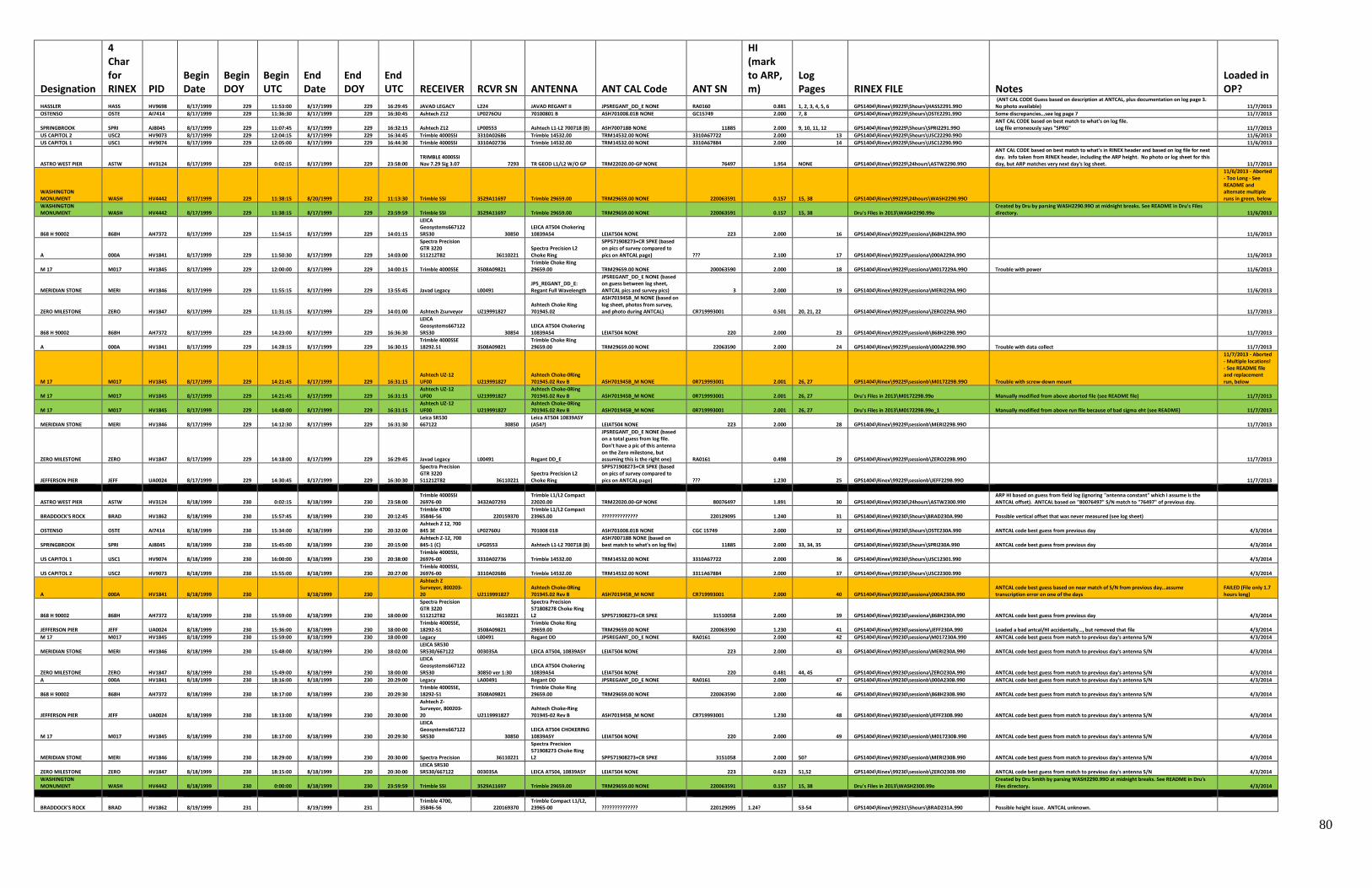
80
Designation
4 Char for RINEX PID
Begin Date
Begin DOY
Begin UTC
End Date
End DOY
End UTC RECEIVER RCVR SN ANTENNA ANT CAL Code ANT SN
HI (mark to ARP, m)
Log Pages RINEX FILE Notes
Loaded in OP?
HASSLER HASS HV9698 8/17/1999 229 11:53:00 8/17/1999 229 16:29:45 JAVAD LEGACY L224 JAVAD REGANT II JPSREGANT_DD_E NONE RA0160 0.881 1, 2, 3, 4, 5, 6 GPS1404\Rinex\99229\5hours\HASS2291.99O (ANT CAL CODE Guess based on description at ANTCAL, plus documentation on log page 3. No photo available) 11/7/2013
OSTENSO OSTE AI7414 8/17/1999 229 11:36:30 8/17/1999 229 16:30:45 Ashtech Z12 LP0276OU 70100801 B ASH701008.01B NONE GC15749 2.000 7, 8 GPS1404\Rinex\99229\5hours\OSTE2291.99O Some discrepancies…see log page 7 11/7/2013
SPRINGBROOK SPRI AJ8045 8/17/1999 229 11:07:45 8/17/1999 229 16:32:15 Ashtech Z12 LP00553 Ashtech L1-L2 700718 (B) ASH700718B NONE 11885 2.000 9, 10, 11, 12 GPS1404\Rinex\99229\5hours\SPRI2291.99O ANT CAL CODE based on best match to what's on log file. Log file erroneously says "SPRG" 11/7/2013
US CAPITOL 2 USC2 HV9073 8/17/1999 229 12:04:15 8/17/1999 229 16:34:45 Trimble 4000SSI 3310A02686 Trimble 14532.00 TRM14532.00 NONE 3310A67722 2.000 13 GPS1404\Rinex\99229\5hours\USC22290.99O 11/6/2013
US CAPITOL 1 USC1 HV9074 8/17/1999 229 12:05:00 8/17/1999 229 16:44:30 Trimble 4000SSI 3310A02736 Trimble 14532.00 TRM14532.00 NONE 3310A67884 2.000 14 GPS1404\Rinex\99229\5hours\USC12290.99O 11/6/2013
ASTRO WEST PIER ASTW HV3124 8/17/1999 229 0:02:15 8/17/1999 229 23:58:00 TRIMBLE 4000SSI Nav 7.29 Sig 3.07 7293 TR GEOD L1/L2 W/O GP TRM22020.00-GP NONE 76497 1.954 NONE GPS1404\Rinex\99229\24hours\ASTW2290.99O
ANT CAL CODE based on best match to what's in RINEX header and based on log file for next day. Info taken from RINEX header, including the ARP height. No photo or log sheet for this day, but ARP matches very next day's log sheet. 11/7/2013
WASHINGTON MONUMENT WASH HV4442 8/17/1999 229 11:38:15 8/20/1999 232 11:13:30 Trimble SSI 3529A11697 Trimble 29659.00 TRM29659.00 NONE 220063591 0.157 15, 38 GPS1404\Rinex\99229\24hours\WASH2290.99O
11/6/2013 - Aborted - Too Long - See README and alternate multiple runs in green, below
WASHINGTON MONUMENT WASH HV4442 8/17/1999 229 11:38:15 8/17/1999 229 23:59:59 Trimble SSI 3529A11697 Trimble 29659.00 TRM29659.00 NONE 220063591 0.157 15, 38 Dru's Files in 2013\WASH2290.99o
Created by Dru by parsing WASH2290.99O at midnight breaks. See README in Dru's Files directory. 11/6/2013
868 H 90002 868H AH7372 8/17/1999 229 11:54:15 8/17/1999 229 14:01:15
LEICA Geosystems667122 SR530 30850
LEICA AT504 Chokering 10839A54 LEIAT504 NONE 223 2.000 16 GPS1404\Rinex\99229\sessiona\868H229A.99O 11/6/2013
A 000A HV1841 8/17/1999 229 11:50:30 8/17/1999 229 14:03:00
Spectra Precision GTR 3220 511212T82 36110221
Spectra Precision L2 Choke Ring
SPP571908273+CR SPKE (based on pics of survey compared to pics on ANTCAL page) ??? 2.100 17 GPS1404\Rinex\99229\sessiona\000A229A.99O 11/6/2013
M 17 M017 HV1845 8/17/1999 229 12:00:00 8/17/1999 229 14:00:15 Trimble 4000SSE 3508A09821 Trimble Choke Ring 29659.00 TRM29659.00 NONE 200063590 2.000 18 GPS1404\Rinex\99229\sessiona\M017229A.99O Trouble with power 11/6/2013
MERIDIAN STONE MERI HV1846 8/17/1999 229 11:55:15 8/17/1999 229 13:55:45 Javad Legacy L00491 JPS_REGANT_DD_E: Regant Full Wavelength
JPSREGANT_DD_E NONE (based on guess between log sheet, ANTCAL pics and survey pics) 3 2.000 19 GPS1404\Rinex\99229\sessiona\MERI229A.99O 11/6/2013
ZERO MILESTONE ZERO HV1847 8/17/1999 229 11:31:15 8/17/1999 229 14:01:00 Ashtech Zsurveyor UZ19991827 Ashtech Choke Ring 701945.02
ASH701945B_M NONE (based on log sheet, photos from survey, and photo during ANTCAL) CR719993001 0.501 20, 21, 22 GPS1404\Rinex\99229\sessiona\ZERO229A.99O 11/7/2013
868 H 90002 868H AH7372 8/17/1999 229 14:23:00 8/17/1999 229 16:36:30
LEICA Geosystems667122 SR530 30854
LEICA AT504 Chokering 10839A54 LEIAT504 NONE 220 2.000 23 GPS1404\Rinex\99229\sessionb\868H229B.99O 11/7/2013
A 000A HV1841 8/17/1999 229 14:28:15 8/17/1999 229 16:30:15 Trimble 4000SSE 18292.51 3508A09821
Trimble Choke Ring 29659.00 TRM29659.00 NONE 22063590 2.000 24 GPS1404\Rinex\99229\sessionb\000A229B.99O Trouble with data collect 11/7/2013
M 17 M017 HV1845 8/17/1999 229 14:21:45 8/17/1999 229 16:31:15 Ashtech UZ-12 UF00 U219991827
Ashtech Choke-0Ring 701945.02 Rev B ASH701945B_M NONE 0R719993001 2.001 26, 27 GPS1404\Rinex\99229\sessionb\M017229B.99O Trouble with screw-down mount
11/7/2013 - Aborted - Multiple locations! - See README file and replacement run, below
M 17 M017 HV1845 8/17/1999 229 14:21:45 8/17/1999 229 16:31:15 Ashtech UZ-12 UF00 U219991827
Ashtech Choke-0Ring 701945.02 Rev B ASH701945B_M NONE 0R719993001 2.001 26, 27 Dru's Files in 2013\M017229B.99o Manually modified from above aborted file (see README file) 11/7/2013
M 17 M017 HV1845 8/17/1999 229 14:48:00 8/17/1999 229 16:31:15 Ashtech UZ-12 UF00 U219991827
Ashtech Choke-0Ring 701945.02 Rev B ASH701945B_M NONE 0R719993001 2.001 26, 27 Dru's Files in 2013\M017229B.99o_1 Manually modified from above run file because of bad sigma eht (see README) 11/7/2013
MERIDIAN STONE MERI HV1846 8/17/1999 229 14:12:30 8/17/1999 229 16:31:30 Leica SR530 667122 30850
Leica AT504 10839ASY (A54?) LEIAT504 NONE 223 2.000 28 GPS1404\Rinex\99229\sessionb\MERI229B.99O 11/7/2013
ZERO MILESTONE ZERO HV1847 8/17/1999 229 14:18:00 8/17/1999 229 16:29:45 Javad Legacy L00491 Regant DD_E
JPSREGANT_DD_E NONE (based on a total guess from log file. Don't have a pic of this antenna on the Zero milestone, but assuming this is the right one) RA0161 0.498 29 GPS1404\Rinex\99229\sessionb\ZERO229B.99O 11/7/2013
JEFFERSON PIER JEFF UA0024 8/17/1999 229 14:30:45 8/17/1999 229 16:30:30
Spectra Precision GTR 3220 511212T82 36110221
Spectra Precision L2 Choke Ring
SPP571908273+CR SPKE (based on pics of survey compared to pics on ANTCAL page) ??? 1.230 25 GPS1404\Rinex\99229\sessionb\JEFF229B.99O 11/7/2013
ASTRO WEST PIER ASTW HV3124 8/18/1999 230 0:02:15 8/18/1999 230 23:58:00 Trimble 4000SSI 26976-00 3432A07293
Trimble L1/L2 Compact 22020.00 TRM22020.00-GP NONE 80076497 1.891 30 GPS1404\Rinex\99230\24hours\ASTW2300.990
ARP HI based on guess from field log (ignoring "antenna constant" which I assume is the ANTCAL offset). ANTCAL based on "80076497" S/N match to "76497" of previous day.
BRADDOCK'S ROCK BRAD HV1862 8/18/1999 230 15:57:45 8/18/1999 230 20:12:45 Trimble 4700 35846-56 220159370
Trimble L1/L2 Compact 23965.00 ?????????????? 220129095 1.240 31 GPS1404\Rinex\99230\5hours\BRAD230A.990 Possible vertical offset that was never measured (see log sheet)
OSTENSO OSTE AI7414 8/18/1999 230 15:34:00 8/18/1999 230 20:32:00 Ashtech Z 12, 700 845 3E LP02760U 701008 01B ASH701008.01B NONE CGC 15749 2.000 32 GPS1404\Rinex\99230\5hours\OSTE230A.990 ANTCAL code best guess from previous day 4/3/2014
SPRINGBROOK SPRI AJ8045 8/18/1999 230 15:45:00 8/18/1999 230 20:15:00 Ashtech Z-12, 700 845-1 (C) LPG0553 Ashtech L1-L2 700718 (B)
ASH700718B NONE (based on best match to what's on log file) 11885 2.000 33, 34, 35 GPS1404\Rinex\99230\5hours\SPRI230A.990 ANTCAL code best guess from previous day 4/3/2014
US CAPITOL 1 USC1 HV9074 8/18/1999 230 16:00:00 8/18/1999 230 20:38:00 Trimble 4000SSI, 26976-00 3310A02736 Trimble 14532.00 TRM14532.00 NONE 3310A67722 2.000 36 GPS1404\Rinex\99230\5hours\USC12301.990 4/3/2014
US CAPITOL 2 USC2 HV9073 8/18/1999 230 15:55:00 8/18/1999 230 20:27:00 Trimble 4000SSI, 26976-00 3310A02686 Trimble 14532.00 TRM14532.00 NONE 3311A67884 2.000 37 GPS1404\Rinex\99230\5hours\USC22300.990 4/3/2014
A 000A HV1841 8/18/1999 230 8/18/1999 230
Ashtech Z Surveyor, 800203-20 U2119991827
Ashtech Choke-0Ring 701945.02 Rev B ASH701945B_M NONE CR719993001 2.000 40 GPS1404\Rinex\99230\sessiona\000A230A.990
ANTCAL code best guess based on near match of S/N from previous day…assume transcription error on one of the days
FAILED (File only 1.7 hours long)
868 H 90002 868H AH7372 8/18/1999 230 15:59:00 8/18/1999 230 18:00:00
Spectra Precision GTR 3220 511212T82 36110221
Spectra Precision 571808278 Choke Ring L2 SPP571908273+CR SPKE 31510058 2.000 39 GPS1404\Rinex\99230\sessiona\868H230A.990 ANTCAL code best guess from previous day 4/3/2014
JEFFERSON PIER JEFF UA0024 8/18/1999 230 15:36:00 8/18/1999 230 18:00:00 Trimble 4000SSE, 18292-51 3508A09821
Trimble Choke Ring 29659.00 TRM29659.00 NONE 220063590 1.230 41 GPS1404\Rinex\99230\sessiona\JEFF230A.990 Loaded a bad antcal/HI accidentally…, but removed that file 4/3/2014
M 17 M017 HV1845 8/18/1999 230 15:59:00 8/18/1999 230 18:00:00 Legacy L00491 Regant DD JPSREGANT_DD_E NONE RA0161 2.000 42 GPS1404\Rinex\99230\sessiona\M017230A.990 ANTCAL code best guess from match to previous day's antenna S/N 4/3/2014
MERIDIAN STONE MERI HV1846 8/18/1999 230 15:48:00 8/18/1999 230 18:02:00 LEICA SR530 5R530/667122 003035A LEICA AT504, 10839ASY LEIAT504 NONE 223 2.000 43 GPS1404\Rinex\99230\sessiona\MERI230A.990 ANTCAL code best guess from match to previous day's antenna S/N 4/3/2014
ZERO MILESTONE ZERO HV1847 8/18/1999 230 15:49:00 8/18/1999 230 18:00:00
LEICA Geosystems667122 SR530 30850 ver 1:30
LEICA AT504 Chokering 10839A54 LEIAT504 NONE 220 0.481 44, 45 GPS1404\Rinex\99230\sessiona\ZERO230A.990 ANTCAL code best guess from match to previous day's antenna S/N 4/3/2014
A 000A HV1841 8/18/1999 230 18:16:00 8/18/1999 230 20:29:00 Legacy LA00491 Regant DD JPSREGANT_DD_E NONE RA0161 2.000 47 GPS1404\Rinex\99230\sessionb\000A230B.990 ANTCAL code best guess from match to previous day's antenna S/N 4/3/2014
868 H 90002 868H AH7372 8/18/1999 230 18:17:00 8/18/1999 230 20:29:30 Trimble 4000SSE, 18292-51 3508A09821
Trimble Choke Ring 29659.00 TRM29659.00 NONE 220063590 2.000 46 GPS1404\Rinex\99230\sessionb\868H230B.990 ANTCAL code best guess from match to previous day's antenna S/N 4/3/2014
JEFFERSON PIER JEFF UA0024 8/18/1999 230 18:13:00 8/18/1999 230 20:30:00
Ashtech Z-Surveyor, 800203-20 U2119991827
Ashtech Choke-Ring 701945-02 Rev B ASH701945B_M NONE CR719993001 1.230 48 GPS1404\Rinex\99230\sessionb\JEFF230B.990 ANTCAL code best guess from match to previous day's antenna S/N 4/3/2014
M 17 M017 HV1845 8/18/1999 230 18:17:00 8/18/1999 230 20:29:30
LEICA Geosystems667122 SR530 30850
LEICA AT504 CHOKERING 10839ASY LEIAT504 NONE 220 2.000 49 GPS1404\Rinex\99230\sessionb\M017230B.990 ANTCAL code best guess from match to previous day's antenna S/N 4/3/2014
MERIDIAN STONE MERI HV1846 8/18/1999 230 18:29:00 8/18/1999 230 20:30:00 Spectra Precision 36110221
Spectra Precision 571908273 Choke Ring L2 SPP571908273+CR SPKE 3151058 2.000 50? GPS1404\Rinex\99230\sessionb\MERI230B.990 ANTCAL code best guess from match to previous day's antenna S/N 4/3/2014
ZERO MILESTONE ZERO HV1847 8/18/1999 230 18:15:00 8/18/1999 230 20:30:00 LEICA SR530 SR530/667122 003035A LEICA AT504, 10839ASY LEIAT504 NONE 223 0.623 51,52 GPS1404\Rinex\99230\sessionb\ZERO230B.990 ANTCAL code best guess from match to previous day's antenna S/N 4/3/2014
WASHINGTON MONUMENT WASH HV4442 8/18/1999 230 0:00:00 8/18/1999 230 23:59:59 Trimble SSI 3529A11697 Trimble 29659.00 TRM29659.00 NONE 220063591 0.157 15, 38 Dru's Files in 2013\WASH2300.99o
Created by Dru Smith by parsing WASH2290.99O at midnight breaks. See README in Dru's Files directory. 4/3/2014
BRADDOCK'S ROCK BRAD HV1862 8/19/1999 231 8/19/1999 231 Trimble 4700, 35846-56 220169370
Trimble Compact L1/L2, 23965-00 ?????????????? 220129095 1.24? 53-54 GPS1404\Rinex\99231\5hours\BRAD231A.990 Possible height issue. ANTCAL unknown.
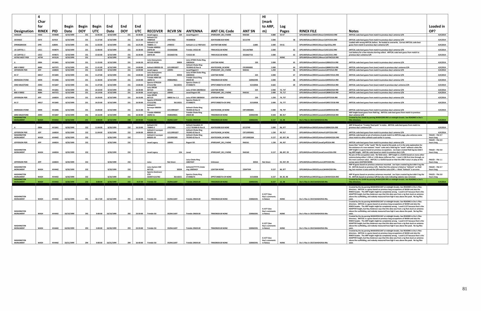
81
Designation
4 Char for RINEX PID
Begin Date
Begin DOY
Begin UTC
End Date
End DOY
End UTC RECEIVER RCVR SN ANTENNA ANT CAL Code ANT SN
HI (mark to ARP, m)
Log Pages RINEX FILE Notes
Loaded in OP?
HASSLER HASS HV9698 8/19/1999 231 12:05:00 8/19/1999 231 16:30:00 Javad Legacy 224 Javad Regant II JPSREGANT_DD_E NONE RA0160 0.880 55-57 GPS1404\Rinex\99231\5hours\HASS231A.990 ANTCAL code best guess from match to previous day's antenna S/N 4/4/2014
OSTENSO OSTE AI7414 8/19/1999 231 11:37:00 8/19/1999 231 16:31:00 Ashtech Z12 7008453E LP02760U 70100801B ASH701008.01B NONE GC15749 2.000 58 GPS1404\Rinex\99231\5hours\OSTE231A.990 ANTCAL code best guess from match to previous day's antenna S/N 4/4/2014
SPRINGBROOK SPRI AJ8045 8/19/1999 231 11:02:00 8/19/1999 231 16:25:00 Ashtech Z-12 700845-1 C LP00553 Ashtech L1-L2 700718 B ASH700718B NONE 11885 2.000 59-61 GPS1404\Rinex\99231\5hours\Spri231a.990
Loaded with wrong ANTCAL before. Re-loaded to overwrite. Correct ANTCAL code best guess from match to previous day's antenna S/N 4/4/2014
US CAPITOL 1 USC1 HV9074 8/19/1999 231 12:00:00 8/19/1999 231 16:38:00 Trimble 4000SSI 26976-00 3310A02686 Trimble 14532-00 TRM14532.00 NONE 3311A67884 2.000 62 GPS1404\Rinex\99231\5hours\USC12312.990 ANTCAL code best guess from match to previous day's antenna S/N 4/4/2014
US CAPITOL 2 USC2 HV9073 8/19/1999 231 12:02:00 8/19/1999 231 16:30:00 Trimble 4000SSI 26976-00 3310A02736 T14532-00 TRM14532.00 NONE 3310A67722 2.000 63 GPS1404\Rinex\99231\5hours\USC22311.990
Lost battery for a few minutes durring collect. ANTCAL code best guess from match to previous day's antenna S/N 4/4/2014
ASTRO WEST PIER ASTW HV3124 8/19/1999 231 8/19/1999 231 NONE GPS1404\Rinex\99231\24hours\ASTW2310.990
A 000A HV1841 8/19/1999 231 11:55:00 8/19/1999 231 14:06:30 Leica Geosystems 667122 SR530 30850
Leica AT504 Choke Ring, 10839A54 LEIAT504 NONE 220 2.000 65 GPS1404\Rinex\99231\sessiona\000A231A.990 ANTCAL code best guess from match to previous day's antenna S/N 4/4/2014
868 H 90002 868H AH7372 8/19/1999 231 11:41:00 8/19/1999 231 14:00:00 Ashtech 800203-20 U2119991827 Ashtech Choke Ring 7019945-02 Rev B ASH701945B_M NONE CR19993001 2.000 64 GPS1404\Rinex\99231\sessiona\868H231A.990 ANTCAL code best guess from (near) match to previous day's antenna S/N 4/4/2014
JEFFERSON PIER JEFF UA0024 8/19/1999 231 11:44:00 8/19/1999 231 14:00:00 Javad Legacy L00491 Javad Regant II JPSREGANT_DD_E NONE RA0161 1.250 66 GPS1404\Rinex\99231\sessiona\JEFF231A.990 ANTCAL code best guess from match to previous day's antenna S/N 4/4/2014
M 17 M017 HV1845 8/19/1999 231 11:27:00 8/19/1999 231 14:00:00 Leica Geosystems 667122 SR530 30354
Leica AT504 Choke Ring, 10839A54 LEIAT504 NONE 223 2.000 67 GPS1404\Rinex\99231\sessiona\M017231A.990 ANTCAL code best guess from match to previous day's antenna S/N 4/4/2014
MERIDIAN STONE MERI HV1846 8/19/1999 231 11:30:00 8/19/1999 231 14:00:00 Trimble 4000 SSE 18292-51 3908A09821
Trimble Chock Ring 29659-00 TRM29659.00 NONE 220063590 2.000 68 GPS1404\Rinex\99231\sessiona\MERI231A.990 ANTCAL code best guess from match to previous day's antenna S/N 4/4/2014
ZERO MILESTONE ZERO HV1847 8/19/1999 231 11:47:00 8/19/1999 231 14:00:00 Spectra GTR3220 571212782 36110221
Spectra Choke L2 571908273 SPP571908273+CR SPKE 31510058 0.665 69 GPS1404\Rinex\99231\sessiona\ZERO231A.990 ANTCAL code best guess from (near) match to previous day's antenna S/N 4/4/2014
A 000A HV1841 8/19/1999 231 14:10:00 8/19/1999 231 16:30:00 Leica SR530 667123 3035A Leica AT504 108398A54 LEIAT504 NONE 223 2.000 72, 73? GPS1404\Rinex\99231\sessionb\000A231B.990 ANTCAL code best guess from match to previous day's antenna S/N 4/4/2014
868 H 90002 868H AH7372 8/19/1999 231 14:14:00 8/19/1999 231 16:30:00 Javad Legacy L00491 Javad Regant-DD JPSREGANT_DD_E NONE RA0161 2.000 70, 71? GPS1404\Rinex\99231\sessionb\868H231B.990 ANTCAL code best guess from match to previous day's antenna S/N 4/4/2014
JEFFERSON PIER JEFF UA0024 8/19/1999 231 14:20:00 8/19/1999 231 16:33:00 Leica SR530 667123 30850 Ver 1.3 Leica AT504 10839A54 LEIAT504 NONE 220 1.250 74, 75? GPS1404\Rinex\99231\sessionb\JEFF231B.990 ANTCAL code best guess from match to previous day's antenna S/N 4/4/2014
M 17 M017 HV1845 8/19/1999 231 14:25:00 8/19/1999 231 16:30:00 Spectra GTR3220 571212782 36110221
Spectra Choke L2 571908273 SPP571908273+CR SPKE 31510058 2.000 76, 77? GPS1404\Rinex\99231\sessionb\M017231B.990 ANTCAL code best guess from match to previous day's antenna S/N 4/4/2014
MERIDIAN STONE MERI HV1846 8/19/1999 231 14:09:00 8/19/1999 231 16:31:00
Ashtech Z-Surveyor 000203-70 U2119991827
Ashtech Choke Ring 701945-02 Rev B ASH701945B_M NONE CR719993001 2.000 78, 79? GPS1404\Rinex\99231\sessionb\MERI231B.990 ANTCAL code best guess from match to previous day's antenna S/N 4/4/2014
ZERO MILESTONE ZERO HV1847 8/19/1999 231 14:16:00 8/19/1999 231 16:30:00 Trimble 4000SSE 18292-51 3508A09821
Trimble Choke Ring 29659-00 TRM29659.00 NONE 220063590 0.504 80, 81? GPS1404\Rinex\99231\sessionb\ZERO231B.990
ARP height buest guess from field log. ANTCAL code best guess from match to previous day's antenna S/N
WASHINGTON MONUMENT WASH HV4442 8/19/1999 231 0:00:00 8/19/1999 230 23:59:00 Trimble SSI 3529A11697 Trimble 29659.00 TRM29659.00 NONE 220063591 0.157 15, 38 Dru's Files in 2013\WASH2310.99o
Created by Dru Smith by parsing WASH2290.99O at midnight breaks. See README in Dru's Files directory. 4/4/2014
A 000A HV1841 8/20/1999 232 11:04:00 8/20/1999 232 16:10:00 Ashtech Z12 700845-3 LP02760U
Ashtech Geodetic III L1/L2 701008-01 Rev B ASH701008.01B NONE GC15749 2.000 96, 97? GPS1404\Rinex\99232\Ashtech\000A232A.990
ARP HI based on "2 meter fixed pole" in notes. ANTCAL code best guess from match to previous day's antenna S/N 4/4/2014
JEFFERSON PIER JEFF UA0024 8/20/1999 232 11:04:00 8/20/1999 232 14:06:00 Ashtech Z-surveyor 800203-10 U2119991827
Ashtech Choke Ring 701945-02 Rev B ASH701945B_M NONE CR719993001 1.230 90, 91? GPS1404\Rinex\99232\Ashtech\JEFF232A.990 ANTCAL code best guess from match to previous day's antenna S/N 4/4/2014
WASHINGTON MONUMENT WASH HV4442 8/20/1999 232 8/20/1999 232
Ashtech Z-surveyor 800203-20 U219992305
Ashtech Choke Ring 701945-02 Rev B ASH701945B_M NONE CR719992304 0.157 82, 83?, 98 GPS1404\Rinex\99232\Ashtech\WASH232A.990
ANTCAL code based on pic of antenna at peak match to ANTCAL page, plus antenna name close match to other ashtech used earlier in survey.
FAILED : File 0.7 hours long
JEFFERSON PIER JEFF UA0024 8/20/1999 232 8/20/1999 232 Javad Legacy L00491 Regant DD JPSREGANT_DD_E NONE RA0161 1.230 94, 95? GPS1404\Rinex\99232\Javad\jeff232A.990 ANTCAL code best guess from match to previous day's antenna S/N FAILED : File 0.9 hours long
WASHINGTON MONUMENT WASH UA0024 8/20/1999 232 8/20/1999 232 Javad Legacy 224 Javad JPSREGANT_DD_E NONE RA0160 0.157 88, 89?, 99 GPS1404\Rinex\99232\Javad\mont232A.990
Guess that "mont" is the "wash" file for Javad at the peak, as it is the only explanation for the existence of a non-existent "mont" code and a field log for "wash" without a data file. ARP height is a guess based on previous occupations. Joe Evjen created field log but didn't log ARP height. ANTCAL code based on match to previous day's S/N.
FAILED : File 0.8 hours long
JEFFERSON PIER JEFF UA0024 8/20/1999 232 8/20/1999 232 Leica Not Given Leica Choke Ring 10837ASY Unknown 30354 Not Given 92, 93?, 99 GPS1404\Rinex\99232\Leica\JEFF2320.99o
No pics of this occupation exist. No field notes. ARP height is a GUESS based on every other antenna being either 1.230 or 1.250 above Jefferson Pier. I used 1.230 first time through, as the more common value. ANTCAL is a GUESS based on that the ONLY Leica's in play at this survey were LEIAT504 NONE.
FAILED : File 1.1 hours long
WASHINGTON MONUMENT WASH HV4442 8/20/1999 232 8/20/1999 232
Leica System 500 667122 30354
Ashtech(??????) choke ring 10839ASY LEIAT504 NONE 220AT504 0.157 86, 87? GPS1404\Rinex\99232\Leica\WASH2320.99o
ARP HI guess based on previous antennae mounted. Joe Evjen created log but didn't log the HI. ANTCAL based on previous S/N. Note that the antenna is listed as "Ashtech" on field log, but receiver is Leica and the S/N matches Leica S/N's. I think "Ashtech" is an error.
FAILED : File 0.7 hours long
WASHINGTON MONUMENT WASH HV4442 8/20/1999 232 8/20/1999 232
Spectra Geotracer GTR 3220571212782 36110221
Spectra Choke Ring 571908273 SPP571908273+CR NONE 31510058 0.157 84, 85, 98 GPS1404\Rinex\99232\Spectra\WASH232A.99O
ARP HI guess based on previous antennae mounted. Joe Evjen created log but didn't log the HI. ANTCAL based on previous S/N but also note indicating radome was removed.
FAILED : File 0.8 hours long
WASHINGTON MONUMENT WASH HV4442 8/20/1999 232 0:00:00 8/20/1999 232 9:37:30 Trimble SSI 3529A11697 Trimble 29659.00 TRM29659.00 NONE 220063591 0.157 15, 38 Dru's Files in 2013\WASH2320.99o
Created by Dru Smith by parsing WASH2290.99O at midnight breaks. See README in Dru's Files directory. 4/4/2014
WASHINGTON MONUMENT WASH HV4442 10/18/1999 291 18:17:00 10/18/1999 291 23:58:30 Trimble SSI 3529A11697 Trimble 29659.00 TRM29659.00 NONE 220063591
0.157? (See Roy's comments in Notes) NONE Dru's Files in 2013\WASH2910.99o
Created by Dru by parsing WASH2910.DAT at midnight breaks. See README in Dru's Files directory. ANTCAL is a guess based on previous long occupations of WASH and also the RINEX header. The ARP height might be completely wrong. I used 0.157 because that is the ADAPTER height, but Roy Anderson says that this data was from a rig that stuck an antenna above the scaffolding, and nobody measured how high it was above the peak. No log files exist.
WASHINGTON MONUMENT WASH HV4442 10/19/1999 292 0:00:00 10/19/1999 292 23:59:00 Trimble SSI 3529A11697 Trimble 29659.00 TRM29659.00 NONE 220063591
0.157? (See Roy's comments in Notes) NONE Dru's Files in 2013\WASH2910.99o
Created by Dru by parsing WASH2910.DAT at midnight breaks. See README in Dru's Files directory. ANTCAL is a guess based on previous long occupations of WASH and also the RINEX header. The ARP height might be completely wrong. I used 0.157 because that is the ADAPTER height, but Roy Anderson says that this data was from a rig that stuck an antenna above the scaffolding, and nobody measured how high it was above the peak. No log files exist.
WASHINGTON MONUMENT WASH HV4442 10/20/1999 293 0:00:00 10/20/1999 293 23:59:00 Trimble SSI 3529A11697 Trimble 29659.00 TRM29659.00 NONE 220063591
0.157? (See Roy's comments in Notes) NONE Dru's Files in 2013\WASH2910.99o
Created by Dru by parsing WASH2910.DAT at midnight breaks. See README in Dru's Files directory. ANTCAL is a guess based on previous long occupations of WASH and also the RINEX header. The ARP height might be completely wrong. I used 0.157 because that is the ADAPTER height, but Roy Anderson says that this data was from a rig that stuck an antenna above the scaffolding, and nobody measured how high it was above the peak. No log files exist.
WASHINGTON MONUMENT WASH HV4442 10/21/1999 294 0:00:00 10/21/1999 294 16:40:00 Trimble SSI 3529A11697 Trimble 29659.00 TRM29659.00 NONE 220063591
0.157? (See Roy's comments in Notes) NONE Dru's Files in 2013\WASH2910.99o
Created by Dru by parsing WASH2910.DAT at midnight breaks. See README in Dru's Files directory. ANTCAL is a guess based on previous long occupations of WASH and also the RINEX header. The ARP height might be completely wrong. I used 0.157 because that is the ADAPTER height, but Roy Anderson says that this data was from a rig that stuck an antenna above the scaffolding, and nobody measured how high it was above the peak. No log files exist.
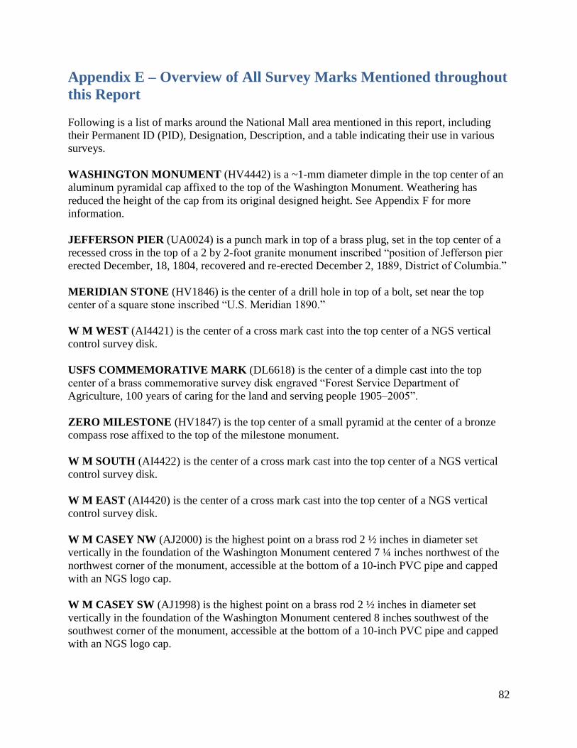
82
Appendix E – Overview of All Survey Marks Mentioned throughout
this Report
Following is a list of marks around the National Mall area mentioned in this report, including
their Permanent ID (PID), Designation, Description, and a table indicating their use in various
surveys.
WASHINGTON MONUMENT (HV4442) is a ~1-mm diameter dimple in the top center of an
aluminum pyramidal cap affixed to the top of the Washington Monument. Weathering has
reduced the height of the cap from its original designed height. See Appendix F for more
information.
JEFFERSON PIER (UA0024) is a punch mark in top of a brass plug, set in the top center of a
recessed cross in the top of a 2 by 2-foot granite monument inscribed “position of Jefferson pier
erected December, 18, 1804, recovered and re-erected December 2, 1889, District of Columbia.”
MERIDIAN STONE (HV1846) is the center of a drill hole in top of a bolt, set near the top
center of a square stone inscribed “U.S. Meridian 1890.”
W M WEST (AI4421) is the center of a cross mark cast into the top center of a NGS vertical
control survey disk.
USFS COMMEMORATIVE MARK (DL6618) is the center of a dimple cast into the top
center of a brass commemorative survey disk engraved “Forest Service Department of
Agriculture, 100 years of caring for the land and serving people 1905–2005”.
ZERO MILESTONE (HV1847) is the top center of a small pyramid at the center of a bronze
compass rose affixed to the top of the milestone monument.
W M SOUTH (AI4422) is the center of a cross mark cast into the top center of a NGS vertical
control survey disk.
W M EAST (AI4420) is the center of a cross mark cast into the top center of a NGS vertical
control survey disk.
W M CASEY NW (AJ2000) is the highest point on a brass rod 2 ½ inches in diameter set
vertically in the foundation of the Washington Monument centered 7 ¼ inches northwest of the
northwest corner of the monument, accessible at the bottom of a 10-inch PVC pipe and capped
with an NGS logo cap.
W M CASEY SW (AJ1998) is the highest point on a brass rod 2 ½ inches in diameter set
vertically in the foundation of the Washington Monument centered 8 inches southwest of the
southwest corner of the monument, accessible at the bottom of a 10-inch PVC pipe and capped
with an NGS logo cap.

83
W M CASEY NE (AJ1996) is the highest point on a brass rod 2 ½ inches in diameter set
vertically in the foundation of the Washington Monument centered 18 ½ inches northeast of the
northeast corner of the monument, accessible at the bottom of a 10-inch PVC pipe and capped
with an NGS logo cap.
W M CASEY SE (AJ1999) is the highest point on a brass rod 2 ½ inches in diameter set
vertically in the foundation of the Washington Monument centered 15 ½ southeast of the
southeast corner of the monument, accessible at the bottom of a 10-inch PVC pipe and capped
with an NGS logo cap.
W M BASE NW (AI4424) is the highest point on an iron plate (or bar) (4 x 1 ½ x ¼ inches)
attached to the west side of the foundation of the Washington Monument and whose northmost
edge is 8 ½ inches south of the northwest corner of the foundation and 9 ½ inches below the
pavers. It is speculated that this mark is the same as mark “O” (PID HV7871).
W M BASE NE (AI4425) is the highest point on an iron plate (or bar) (4 x 1 ½ x ¼ inches)
attached to the east side of the foundation of the Washington Monument and whose northmost
edge is 7 ½ inches south of the northeast corner of the foundation and 7 inches below the pavers.
It is speculated that this mark is the same as mark “N” (PID HV7868).
W M BASE SW (AJ2001) is the highest point on an iron plate (or bar) (4 x 1 ½ x ¼ inches)
attached to the south side of the foundation of the Washington Monument and whose westmost
edge is 11 inches east of the southwest corner of the foundation and 10 inches below the pavers.
As of 2014, it is found to be severely bent upwards so that its highest point is exactly 2 inches
above the point where it attaches to the foundation. It is speculated that this mark is the same as
mark “B 1” (PID HV7866).
W M BASE SE (AI4423) is the highest point on an iron plate (or bar) (4 x 1 ½ x ¼ inches)
attached to the south side of the foundation of the Washington Monument and whose eastmost
edge is 8 inches west of the southeast corner of the foundation and 7 inches below the pavers. As
of 2014, it is found to be severely rotated (clockwise) so that its highest point is its west edge. It
is speculated that this mark is the same as mark “M” (PID HV7865).
A 8 (HV8076) is the top of an aluminum rod inserted into an uncapped hole on the north face of
the Washington Monument near the northeast corner. It only exists as a surveyable point when
the cap is removed and the proper rod inserted.
B 8 (HV8077) is the top of an aluminum rod inserted into an uncapped hole on the south face of
the Washington Monument near the southwest corner. It only exists as a surveyable point when
the cap is removed and the proper rod inserted.
A (HV1841) also called the “mini monument” is the highest point of a 12 ¾ foot high obelisk,
set in a brick well, capped by a manhole cover, on the south lawn of the Washington Monument.
The top is a 3 x 3 inch square. As of 2014, a large gouge exists on the west 1/3 of the top face,
though this does not prevent using the rest of the top face as a mark.

84
I=M 8=TIDAL (HV1838) is a chiseled cross (+) approximately 1 ½ inches in diameter on the
northeast corner of the front stoop to the visitor’s center of the Washington Monument. It is
much faded from almost 100 years of erosion, but remains discernable upon careful examination.
W M ROD NW (DP2631) is the top of a 1-inch diameter metal rod set vertically in the
foundation of the WM about 4 ¼ inches south of the center of mark W M CASEY NW.
Because discussions with CTBUH were ongoing during the actual survey of the WM, the
following four points were chosen during the survey as likely candidates to fulfill the CTBUH
definition of “level of the lowest, significant, open-air, pedestrian entrance.” Final consultation
with CTBUH determined that the actual architectural height of the WM was to be referred to
point “W M FLOOR 3.” None of these marks have anything permanently installed, punched,
or scribed to identify them (to preserve the look of the inside of the WM). Nonetheless, they
may be uniquely identified through the descriptions below.
W M FLOOR 1 (DP2632) is inside the Washington Monument, in the George Washington
Statue alcove, on the mosaic floor, at the east tip of the shield. This point was chosen because the
mosaic floor itself appeared to be somewhat older than the tile floor at the east face of the
elevator and entrance area in general, plus it was protected from wear and tear of passing
pedestrians.
W M FLOOR 2 (DP2633) is inside the Washington Monument, on the tile floor, at the east-
facing wall on the north side of the east door of the elevator. This point was chosen because it
represents the main floor level for pedestrians to access the elevator and stairs.
W M FLOOR 3 (DP2634) is inside the Washington Monument, on the tile floor at the center of
the threshold between the temporary visitor building and the monument proper, being the
original entrance to the monument, at the bottom of a ramp, near the intersection of two
perpendicular grout lines. This point was chosen because it is the first level where a pedestrian
would be located upon entering the original monument.
W M FLOOR 4 (DP2635) is inside the Washington Monument entrance building, on the tile
floor at the threshold of the doorway where pedestrians enter the building. This point was chosen
because it is the first level where a pedestrian would be located upon entering the temporary
building.

85
Table 28: All marks mentioned in this report
DESIGNATION PID GPS 2013
(and its 4
character
RINEX
acronym)
LEVELING
2013 (and
its SSN)
RVAD / HA in
2013 (and its
abbreviation and
serial number in
the Star*NET
adjustment)
OTHER
WASHINGTON
MONUMENT
HV4442 WASH WM/1 GPS 1999 (WASH)
JEFFERSON PIER UA0024 JEFF 1001 JP/6 GPS 1999 (JEFF)
MERIDIAN STONE HV1846 MERI 1017 MS/2 GPS 1999 (MERI)
W M WEST AI4421 WMWE 1015 WMW/5 VA 1999
USFS
COMMEMORATIVE
MARK
DL6618 USFS 1019 COM/3
ZERO MILESTONE HV1847 ZERO 1016 0M/7 GPS 1999 (ZERO)
W M SOUTH AI4422 WMSO VA 1999
W M EAST AI4420 VA 1999
W M CASEY NW AJ2000 1008 LVL 1999
W M CASEY SW AJ1998 1005 LVL 1999 W M CASEY NE AJ1996 1010 LVL 1999 W M CASEY SE AJ1999 1012 LVL 1999 W M BASE NW
8 AI4424
8 1006 LVL 1999
8 W M BASE NE
8 AI44258 1011 LVL 1999
8 W M BASE SW
8 AJ20018 1004 LVL 1999
8 W M BASE SE
8 AI44238 1013 LVL 1999
8 A 8 HV8076 1009 LVL 1999 B 8 HV8077 1003 LVL 1999 A HV1841 000A 1002 GPS1999 (000A) &
LVL 1999
I=M 8=TIDAL HV1838 1018
W M ROD NW DP2631 1007
W M FLOOR 1 DP2632 1021
W M FLOOR 2 DP2633 1022 W M FLOOR 3 DP2634 1023 W M FLOOR 4 DP2635 1024
Below this line are marks that did not participate in the 2013 survey.
M 17 GPS 1999 (M017) 868 H 90002 GPS 1999 (868H) US CAPITOL 1 GPS 1999 (USC1) US CAPITOL 2 GPS 1999 (USC2)
8 It is possible that, in 1999, NGS re-found some very old marks which were last leveled in 1907, and accidentally
gave them new designations. Here are the suspected equivalences:
AJ2001 (W M BASE SW) = HV7866 (B 1)
AI4423 (W M BASE SE) = HV7865 (M)
AI4424 (W M BASE NW) = HV7871 (O)
AI4425 (W M BASE NE) = HV7868 (N)
This speculation is unconfirmed at the time of this report and should not be taken as definitive. Results of this
special investigation will be reported independently when completed.
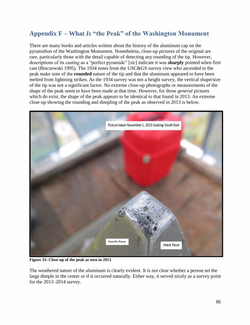
86
Appendix F – What Is “the Peak” of the Washington Monument
There are many books and articles written about the history of the aluminum cap on the
pyramidion of the Washington Monument. Nonetheless, close-up pictures of the original are
rare, particularly those with the detail capable of detecting any rounding of the tip. However,
descriptions of its casting as a “perfect pyramide” [sic] indicate it was sharply pointed when first
cast (Binczewski 1995). The 1934 notes from the USC&GS survey crew who ascended to the
peak make note of the rounded nature of the tip and that the aluminum appeared to have been
melted from lightning strikes. As the 1934 survey was not a height survey, the vertical shape/size
of the tip was not a significant factor. No extreme close-up photographs or measurements of the
shape of the peak seem to have been made at that time. However, for those general pictures
which do exist, the shape of the peak appears to be identical to that found in 2013. An extreme
close-up showing the rounding and dimpling of the peak as observed in 2013 is below.
Figure 33: Close-up of the peak as seen in 2013
The weathered nature of the aluminum is clearly evident. It is not clear whether a person set the
large dimple in the center or if it occurred naturally. Either way, it served nicely as a survey point
for the 2013–2014 survey.
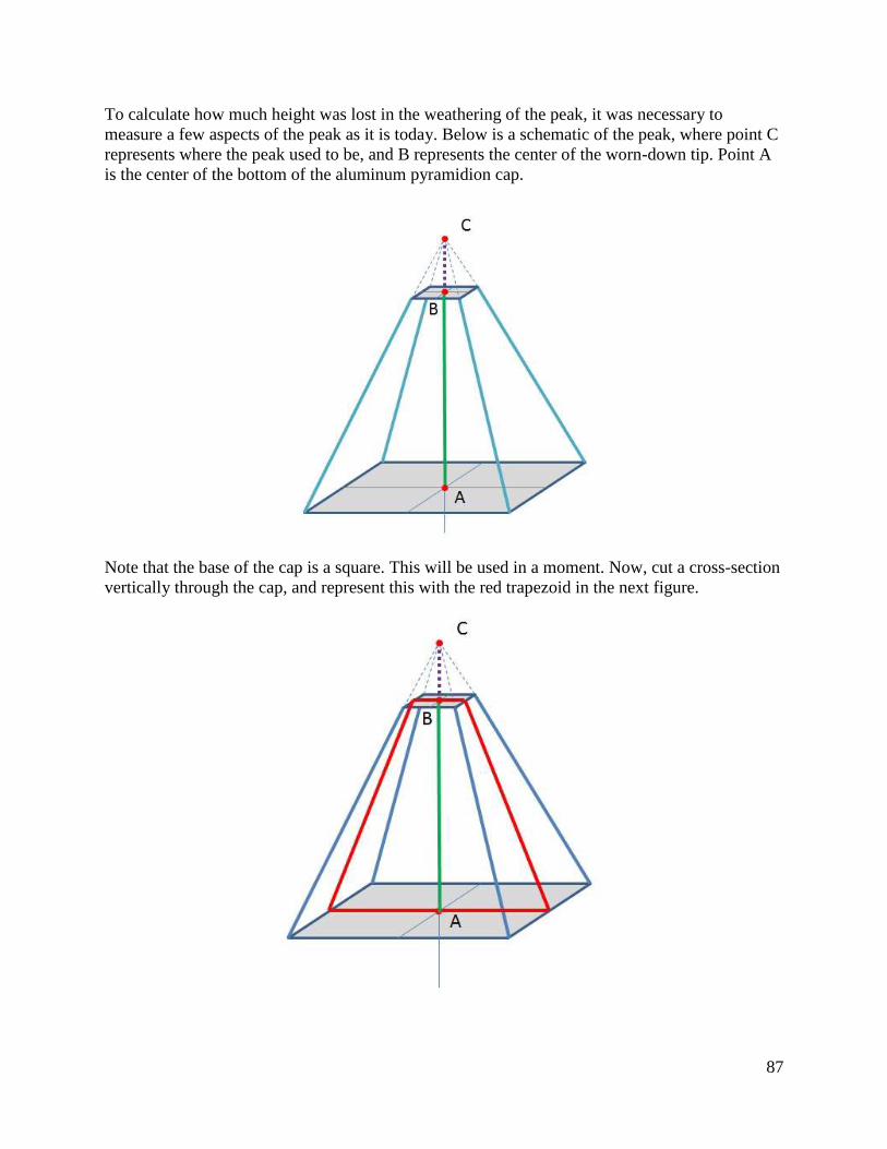
87
To calculate how much height was lost in the weathering of the peak, it was necessary to
measure a few aspects of the peak as it is today. Below is a schematic of the peak, where point C
represents where the peak used to be, and B represents the center of the worn-down tip. Point A
is the center of the bottom of the aluminum pyramidion cap.
Note that the base of the cap is a square. This will be used in a moment. Now, cut a cross-section
vertically through the cap, and represent this with the red trapezoid in the next figure.
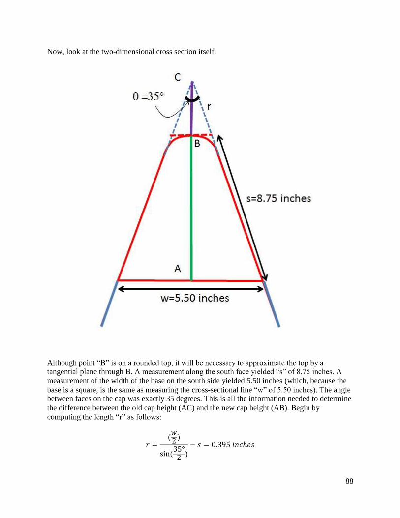
88
Now, look at the two-dimensional cross section itself.
Although point “B” is on a rounded top, it will be necessary to approximate the top by a
tangential plane through B. A measurement along the south face yielded “s” of 8.75 inches. A
measurement of the width of the base on the south side yielded 5.50 inches (which, because the
base is a square, is the same as measuring the cross-sectional line “w” of 5.50 inches). The angle
between faces on the cap was exactly 35 degrees. This is all the information needed to determine
the difference between the old cap height (AC) and the new cap height (AB). Begin by
computing the length “r” as follows:
𝑟 =(𝑤2)
sin(35°2 )
− 𝑠 = 0.395𝑖𝑛𝑐ℎ𝑒𝑠
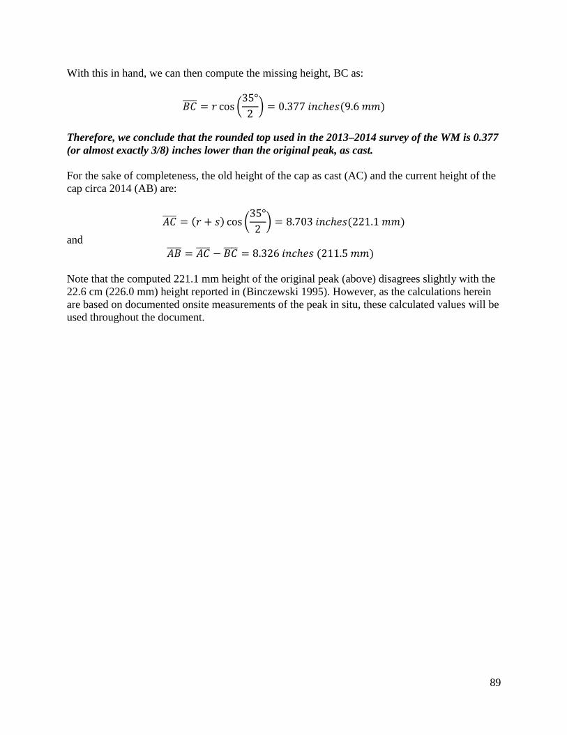
89
With this in hand, we can then compute the missing height, BC as:
𝐵𝐶̅̅ ̅̅ = 𝑟 cos (35°
2) = 0.377𝑖𝑛𝑐ℎ𝑒𝑠(9.6𝑚𝑚)
Therefore, we conclude that the rounded top used in the 2013–2014 survey of the WM is 0.377
(or almost exactly 3/8) inches lower than the original peak, as cast.
For the sake of completeness, the old height of the cap as cast (AC) and the current height of the
cap circa 2014 (AB) are:
𝐴𝐶̅̅ ̅̅ = (𝑟 + 𝑠) cos (35°
2) = 8.703𝑖𝑛𝑐ℎ𝑒𝑠(221.1𝑚𝑚)
and
𝐴𝐵̅̅ ̅̅ = 𝐴𝐶̅̅ ̅̅ − 𝐵𝐶̅̅ ̅̅ = 8.326𝑖𝑛𝑐ℎ𝑒𝑠(211.5𝑚𝑚)
Note that the computed 221.1 mm height of the original peak (above) disagrees slightly with the
22.6 cm (226.0 mm) height reported in (Binczewski 1995). However, as the calculations herein
are based on documented onsite measurements of the peak in situ, these calculated values will be
used throughout the document.

90
Appendix G – The Engravings on the Washington Monument Cap
The aluminum cap on the pyramidion has engravings on all four sides. Although not relevant to
the measurements at the Washington Monument itself, the survey did allow a careful inspection
of the engravings. This appendix is provided purely for the sake of historic information.
Two differences were seen between the reported original engravings and the engravings
inspected in 2014, both explainable:
1. All four sides have been damaged, thus obscuring part of the original engravings.
2. One of the sides had additional engravings not reported as part of the original.
The primary reason for the first difference (damaging obscuration) was the lightning protection
system, installed in 1885 and refurbished in 1934, which was a collar that sat tightly (screwed
against) the original aluminum cap (see Figure 8). When removed in 2013 it was seen that 127
years of wear had occurred where a lightning collar had sat on the original aluminum cap.
According to sources involved in the 2013–2014 earthquake damage repair of the monument, the
restoration of the original engravings was not performed as part of this project.
The reason for the second seems to be that some new engravings had been added to the
aluminum cap in 1934 during the restoration project that year. The only reference to these new
engravings which could be found was in a newspaper article from the Indiana Gazette, dated
January 28, 1935 (Indiana Evening Gazette 1935), referencing an official communication from
the Department of the Interior about the completion of the restoration and with regard to the
engravings, “the addition of the words recording that it was ‘Repaired, 1934, National Park
Service, Department of the Interior.’” That official communication from the Department of the
Interior has not been found.
In Table 29, for each of the four faces, below, the original engraved words (completed and put in
place on the same day: December 6, 1884) are listed in the middle column, and then a color-
coded list of what was visible during the 2013 inspection are in the right column. Letters in
GREEN reflect that the original engraving was found intact; letters in RED reflect that the
original engraving from 1884 was obscured by damage from the lightning collar, and words in
PURPLE reflect new engravings visible in 2013 but not part of the original 1884 engravings.
Photographs of each of the four faces are found after Table 29.

91
Table 29: Original 1884 and found 2013 engravings on the aluminum cap
Original
Engravings What is Visible,
What is Not,
and What is New
North Face
JOINT COMMISSION
AT
SETTING OF CAPSTONE.
CHESTER A. ARTHUR.
W. W. CORCORAN,
Chairman.
M. E. BELL.
EDWARD CLARK.
JOHN NEWTON.
Act of August 2, 1876.
JOINT COMMISSION
AT
SETTING OF CAPSTONE.
CHESTER A. ARTHUR.
W. W. CORCORAN,
Chairman.
M. E. BELL.
EDWARD CLARK.
JOHN NEWTON.
Act of August 2, 1876.
West Face
CORNER STONE LAID ON
BED OF FOUNDATION JULY 4, 1848.
FIRST STONE AT HEIGHT OF
152 FEET LAID AUGUST 7, 1880.
CAPSTONE SET DECEMBER
6, 1884.
CORNER STONE LAID ON
BED OF FOUNDATION JULY 4, 1848.
FIRST STONE AT HEIGHT OF
152 FEET LAID AUGUST 7, 1880.
CAPSTONE SET DECEMBER
6, 1884.
South Face
CHIEF ENGINEER AND
ARCHITECT,
THOS. LINCOLN CASEY,
COLONEL, CORPS OF
ENGINEERS.
Assistants:
GEORGE W. DAVIS,
CAPTAIN, 14TH
INFANTRY.
BERNARD R. GREEN, CIVIL ENGINEER.
Master Mechanic.
P. H. MCLAUGHLIN.
CHIEF ENGINEER AND
ARCHITECT,
THOS. LINCOLN CASEY,
COLONEL, CORPS OF
ENGINEERS.
Assistants:
GEORGE W. DAVIS,
CAPTAIN, 14TH
INFANTRY.
BERNARD R. GREEN, CIVIL ENGINEER.
Master Mechanic.
P. H. MCLAUGHLIN.
East Face
LAUS DEO.
Repaired, 1934,
National Park Service
Department of the Interior
LAUS DEO.
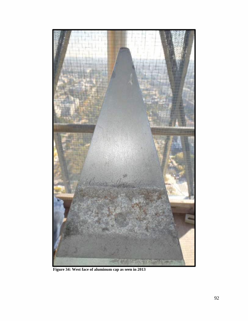
92
Figure 34: West face of aluminum cap as seen in 2013
93
Figure 35: North face of aluminum cap as seen in 2013
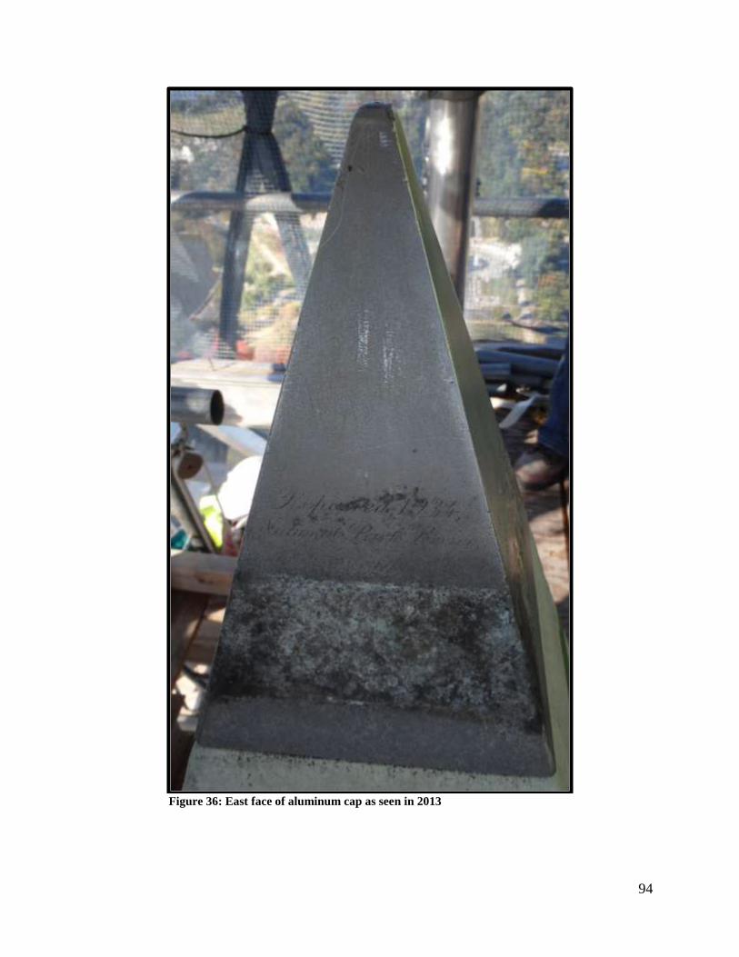
94
Figure 36: East face of aluminum cap as seen in 2013

95
Figure 37: South face of aluminum cap as seen in 2013

96
Appendix H – The History of Measuring the Architectural Height of
the Washington Monument
The computations supporting the original 1885 height of the Washington Monument at 555 feet,
5 1/8 inches were not readily available. Researching archived records to understand the source of
this height was beyond the scope of this survey.
In addition, there is a complex history of reporting who has measured the height of the
monument since then, how they did it, and what value was determined. This appendix does not
attempt to give an exhaustive overview of that history, but rather attempts to give simply an idea
of the confusion dispersed over the years.
Consider the two oldest and clearest references to any sort of architectural height of the WM as
available circa 2014:
1885 Source: Handwritten Annual Report by Lt Col Thomas L. Casey
A height of the finished monument is provided as:
“As finished the Monument is 555 feet 5 1/8 inches in height, the shaft being
500 ft 5 1/8 inches, and the pyramidion or apex 55 feet”
1896 Source: Coast and Geodetic Survey Superintendent’s Report for 1896
A description exists of a bench mark near the WM as:
“The top of a brass bolt, marked O, placed vertically in a stone on the southwest corner
of the top layer of the foundation of the monument. It was established and used by the
Army Engineers in the erection of the monument. The aluminum point of the pyramidion
is said to be 555 feet 4 ½ inches above this bolt.”
Attempts were made to find this bolt, or identify it with other known marks, but they
have not yet been definitively successful. There is speculation that the mark found in
1999 and at that time given its current designation of “W M CASEY SW” is this bolt.
The pieces of evidence supporting this speculation are:
1. The W M CASEY SW mark appears to be made of brass.
2. The 1999 GPS-derived height, relative to W M CASEY SW was 555 feet 3 5/8 inches
(see later in this appendix), matching the 555 feet 4 ½ inches value to about an inch.
3. The 2014 height, relative to W M CASEY SW is 555’ 3 54/64”, which matches the
1896 height to 5/8”, of which 3/8 inch can be explained by the rounding of the tip.
The pieces of evidence against this speculation are:
1. There are four identical brass marks, one at each corner. Why would only one of them
be called out as a height reference point?
2. There was no identifying mark, such as a letter “O” (see above: “…marked O…”) on
W M CASEY SW, until it was stamped in 2014 (see Figure 38).
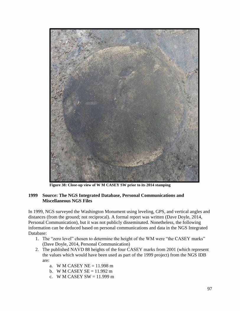
97
Figure 38: Close-up view of W M CASEY SW prior to its 2014 stamping
1999 Source: The NGS Integrated Database, Personal Communications and
Miscellaneous NGS Files
In 1999, NGS surveyed the Washington Monument using leveling, GPS, and vertical angles and
distances (from the ground; not reciprocal). A formal report was written (Dave Doyle, 2014,
Personal Communication), but it was not publicly disseminated. Nonetheless, the following
information can be deduced based on personal communications and data in the NGS Integrated
Database:
1. The “zero level” chosen to determine the height of the WM were “the CASEY marks”
(Dave Doyle, 2014, Personal Communication)
2. The published NAVD 88 heights of the four CASEY marks from 2001 (which represent
the values which would have been used as part of the 1999 project) from the NGS IDB
are:
a. W M CASEY NE = 11.998 m
b. W M CASEY SE = 11.992 m
c. W M CASEY SW = 11.999 m
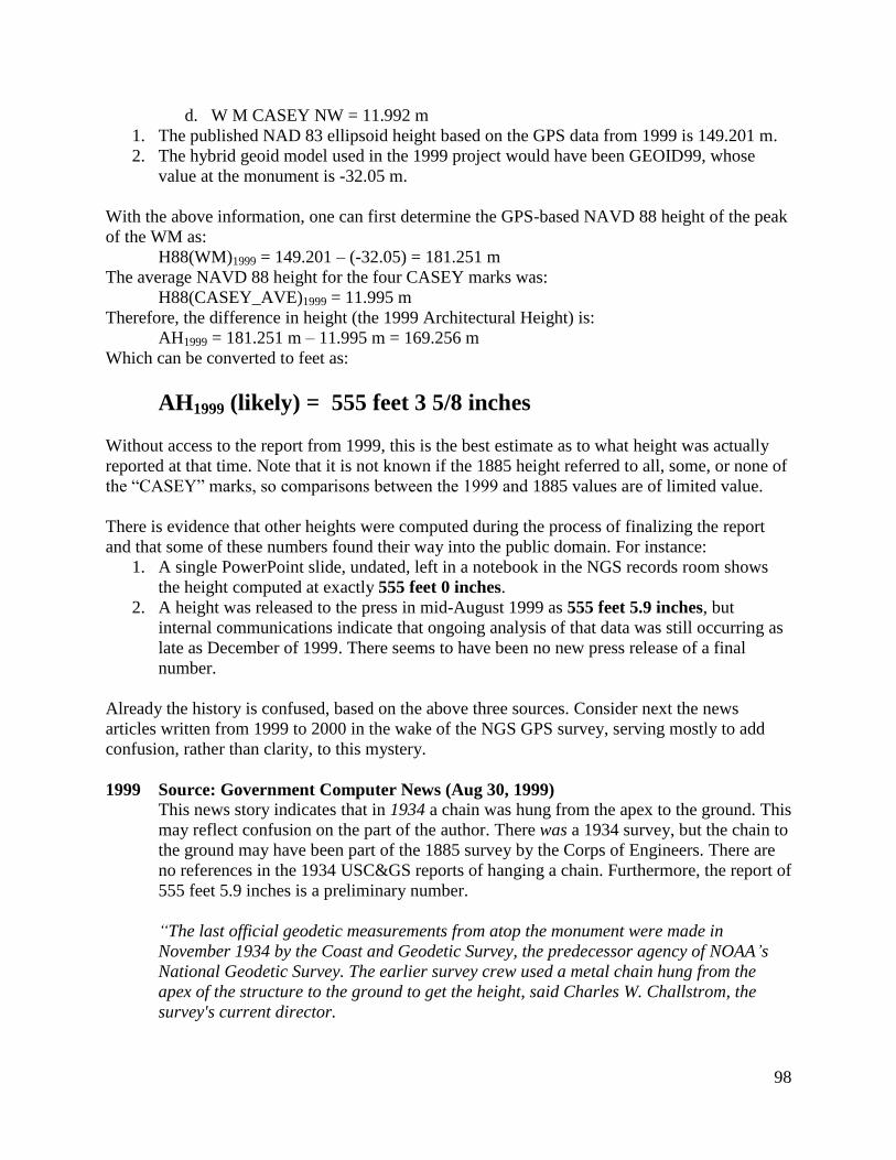
98
d. W M CASEY NW = 11.992 m
1. The published NAD 83 ellipsoid height based on the GPS data from 1999 is 149.201 m.
2. The hybrid geoid model used in the 1999 project would have been GEOID99, whose
value at the monument is -32.05 m.
With the above information, one can first determine the GPS-based NAVD 88 height of the peak
of the WM as:
H88(WM)1999 = 149.201 – (-32.05) = 181.251 m
The average NAVD 88 height for the four CASEY marks was:
H88(CASEY_AVE)1999 = 11.995 m
Therefore, the difference in height (the 1999 Architectural Height) is:
AH1999 = 181.251 m – 11.995 m = 169.256 m
Which can be converted to feet as:
AH1999 (likely) = 555 feet 3 5/8 inches
Without access to the report from 1999, this is the best estimate as to what height was actually
reported at that time. Note that it is not known if the 1885 height referred to all, some, or none of
the “CASEY” marks, so comparisons between the 1999 and 1885 values are of limited value.
There is evidence that other heights were computed during the process of finalizing the report
and that some of these numbers found their way into the public domain. For instance:
1. A single PowerPoint slide, undated, left in a notebook in the NGS records room shows
the height computed at exactly 555 feet 0 inches.
2. A height was released to the press in mid-August 1999 as 555 feet 5.9 inches, but
internal communications indicate that ongoing analysis of that data was still occurring as
late as December of 1999. There seems to have been no new press release of a final
number.
Already the history is confused, based on the above three sources. Consider next the news
articles written from 1999 to 2000 in the wake of the NGS GPS survey, serving mostly to add
confusion, rather than clarity, to this mystery.
1999 Source: Government Computer News (Aug 30, 1999)
This news story indicates that in 1934 a chain was hung from the apex to the ground. This
may reflect confusion on the part of the author. There was a 1934 survey, but the chain to
the ground may have been part of the 1885 survey by the Corps of Engineers. There are
no references in the 1934 USC&GS reports of hanging a chain. Furthermore, the report of
555 feet 5.9 inches is a preliminary number.
“The last official geodetic measurements from atop the monument were made in
November 1934 by the Coast and Geodetic Survey, the predecessor agency of NOAA’s
National Geodetic Survey. The earlier survey crew used a metal chain hung from the
apex of the structure to the ground to get the height, said Charles W. Challstrom, the
survey's current director.

99
The crew measured the monument-which was dedicated by President Chester A. Arthur
in 1885-at 555 feet, 5.5 inches. Sixty-five years later, a NOAA team traded in a chain for
24 Defense Department navigational satellites and portable GPS receivers.
GPS data found it is 555 feet, 5.9 inches. The 1930s-era metal chain was only
0.4 inches off.”
1999 Source: ACSM Bulletin (July/August 1999) This news story re-affirms that a height was determined by the Corps of Engineers in
1885, though the method isn’t clear.
“In 1885, Lt. Col. Thomas Lincoln Casey of the U.S. Army Corps of Engineers reported
on the completion of the Washington Monument. Casey noted that the monument was
555 feet, 5-1 /8 inches in height.”
1999 Source: Federal Computer Week (Aug 23, 1999)
States that the National Park Service determined a height of 555 feet 5.5 inches in 1934.
“…preliminary results from the GPS survey last week indicated that the monument is
555 feet, 5.9 inches tall, four-tenths of an inch taller than the Park Service determined
in 1934.”
2000 Source: Professional Surveyor Magazine (January 2000)
This news story indicates that no attempt to measure the height was made in 1934.
However, it does make a side reference to an 1885 height measurement by the Corps of
Engineers. It also indicates the problem that a new height measurement would need to
use the same reference points as the 1885 survey, which seems impossible at this time.
The first geodetic survey of the Monument was performed shortly after its completion.
From April 4–11, 1886, a field unit of the U.S. Coast and Geodetic Survey (USCGS), the
predecessor of NGS, performed a local triangulation network and computed a third-
order (1:10,000) position by the method of intersection using a 10-inch Gamby
theodolite. These observations were computed as part of the New England Datum, later
readjusted into the U.S. Standard Datum in 1901 and subsequently renamed the North
American Datum in 1913. No attempt was made to determine the elevation during that
survey. During a cleaning and maintenance project in 1934, USCGS actually occupied
the apex as part of a D.C. area triangulation network. The Monument (PID HV4432) was
positioned as a first-order (1:100,000) network station and adjusted into the North
American Datum of 1927. This data was later readjusted as part of the North American
Datum of 1983 in 1986 [NAD 83 (1986)] and again readjusted to fit with the Maryland
High Accuracy Network (HARN), NAD 83 (1991). Unfortunately, again no observations
where performed to determine the height and the published National Geodetic Vertical
Datum of 1929 (NAVD 29) elevation was considered to be no better than scaled from a
topographic map.
100
Before the currently published height of 555 feet, 5 inches can be challenged or
confirmed, every effort must be made to ensure that the same reference points used in the
1884 measurements by the Corps of Engineers are used in the current survey.
This appendix has been provided merely to briefly illustrate the difficulty in unraveling the
history of measurement of the height of the peak. It is in light of this complicated history that
NGS has written this report, with the hope that this new measurement of the position of the peak
and the architectural height of the monument will serve as a standard for future surveys.