no slide title · detectors - faraday cup, electron multiplier. channel plate/fluorescent screen ....
TRANSCRIPT

3-1
Instrumentation
Vacuum system - mean free path, chamber background pressure
Ion sources - duoplasmatron, surface ionization,
liquid metal ion source (LMIS)
Ion optics - ion path simulations
Analyzers - magnetic sector, quadrupole, time of flight
Detectors - Faraday cup, electron multiplier.
channel plate/fluorescent screen

3-2
Mean Free Path in Air
P
Pressure
(Torr)
n
Density
(molecules/cm3)
λ
Mean Free Path
(cm)
760 2.49x10¹⁹ 3.9x10⁻⁶ (40nm)
1 3.25x10¹⁶ 5.1x10⁻³
10-3 3.25x10¹³ 5.1
10-6 3.25x10¹⁰ 5.1x10³ (51m)
10-9 3.25x10⁷ 5.1x10⁶ (51km)
10-12 3.25x10⁴ 5.1x10⁹
SIMS secondary ion path length ~2m for IMS6F
Mean free path: average distance particle travels between collisions

3-3
Chamber Background Pressure Time Available for Analysis
Deposition of gas molecules with sticking coefficient of one:
1x10⁻⁶ torr 1 monolayer deposited/sec
1x10⁻⁹ torr 1 monolayer deposited/1000 sec
Static SIMS limit is 1012 ions/cm2 (surface is 1015 atoms/cm2)
1 nA / (1000 µm x 1000 µm) = 5.25x10¹¹ ions/cm2-sec
< 10 sec to reach static limit
10 pA / (1000 µm x 1000 µm) = 5.25x10⁹ ions/cm2-sec
> 800 sec to reach static limit
Dynamic SIMS may have 150 nA / (200 µm x 200 µm)
= 2.3x10¹⁵ ions/cm2-sec

3-4
General Vacuum Practice
To maintain optimum vacuum level:
• Backfill with dry nitrogen and maintain nitrogen flow
• Wear gloves and use clean tools to prepare and load specimens
• Expose chamber to air for minimum time
• Avoid oil back streaming due to rough pumping too long without
turbopump
• Delay sample insertion into analysis chamber until sample
chamber pressure is sufficiently low
• Bake system when base pressure becomes elevated

3-5
SIMS Instrument Block Diagram
Ion Source Specimen Mass Analyzer
• Quadruple
• Magnetic Sector
• Time of Flight
Vacuum System
Detector
3-6
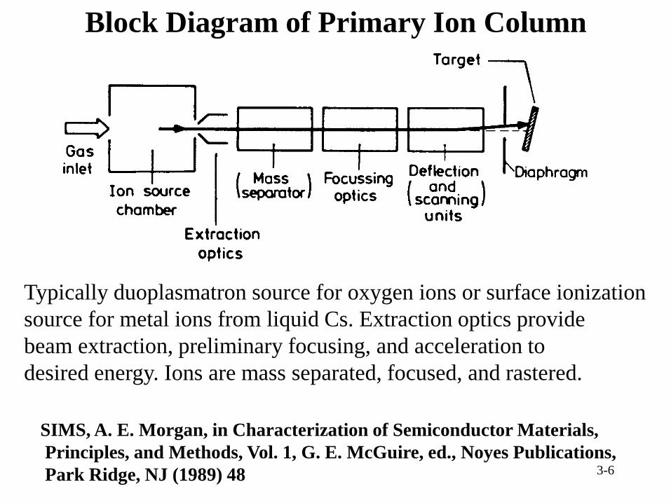
Block Diagram of Primary Ion Column
SIMS, A. E. Morgan, in Characterization of Semiconductor Materials,
Principles, and Methods, Vol. 1, G. E. McGuire, ed., Noyes Publications,
Park Ridge, NJ (1989) 48
Typically duoplasmatron source for oxygen ions or surface ionization
source for metal ions from liquid Cs. Extraction optics provide
beam extraction, preliminary focusing, and acceleration to
desired energy. Ions are mass separated, focused, and rastered.

3-7
Duoplasmatron
Introduction to SIMS, H. W. Werner, in Electron and Ion Spectroscopy of Solids,
L. Fiermans, et al., eds., Plenum Press, New York (1978) 342
Duoplasmatron with hollow
cathode
~10-3 Torr during operation
Beam constricted by shape of
intermediate electrode and by
inhomogeneous magnetic field
near intermediate electrode.

3-8
Duoplasmatron
• Intermediate electrode and coil confine beam
• High ionization efficiency (> 80%)
• Low energy spread (tens of eV)
• High brightness (100 mA/cm2)
• Various gaseous ion species possible

3-9
Duoplasmatron Parts
CAMECA IMS-f series instruments
Anode Intermediate Electrode Cathode

3-10
Cesium Microbeam Source
1. High voltage input
2. Cs2CO3
3. Reservoir
4. Ionizer
5. Tungsten tablet
6. Reservoir filament
7. Ionizer filament
8. Extraction electrode
Cs from Cs2CO3 at 400°C
Cesium ionized on contact
with tungsten at 1100°C
CAMECA Instruments

3-11
Cesium Source
• Cesium vapor strikes hot tungsten (> 1000° C)
• Electron removed from cesium
• Cesium ion evaporates from tungsten due to high temperature
• 5 mA/cm2
• Cs source material:
Cs metal
CsCrO4
Cs2CO3 now used on CAMECA microbeam source

3-12
Schematic Diagram of
Liquid Metal Ion Source (LMIS)
FEI Company

3-13
Liquid Metal Ion Source (LMIS)
• Gallium wets tungsten needle
• High extraction voltage (108 volts/cm, 1 volt/Å)
pulls gallium into Taylor cone
• 5-7 nm beam diameter columns commercially available
• Very high brightness (1 A/cm2)

3-14
Calculated Shape of Liquid Gallium Emitter
“thin” (continuous line) and
“fat” (dashed line) shapes
correspond to different
assumed shape factors
D. R. Kingham and L. W. Swanson,
Appl. Phys. A34, 123 (1984)

Bi Source
Focusing
Pulsing
Focusing
Primary Column
Bi+ source
ION-TOFV

3-16
Simulation of Einzel Lens
Trajectories and equi-potential lines are shown.
SIMION

3-17
Simulation of Electrodynamic Buncher
SIMION
Used to bunch primary ions in time of flight source

3-18
Comparison of Mass Analyzer Types
SIMS, J. C. Vickerman, A. Brown, and N. M. Reed, eds.,
Oxford University Press, Oxford (1989)

3-19
Magnetic Sector Analyzer
+ high mass resolution (10000 -25000)
resolves mass interferences
+ high transmission
best detection limits
+ wide energy bandpass (~ 150 eV)
+ optical gating possible
smaller craters
- large
- expensive
- high extraction field across small gap
- slow mass switching
- typically transmits one mass at a time
some instruments can transmit multiple isotopes
- ion molecule reactions significant for analyzer at 10-6 torr

3-20
SIMS, J. C. Vickerman, et al., eds., Oxford University Press, Oxford (1989)
Magnetic Sector

3-21
Quadrupole Analyzer
+ can be mounted in small area
+ less expensive
+ low sample extraction voltage
low energy primary beam
best depth resolution (ultra-shallow profiles)
+ large extraction area
easy charge neutralization for insulators
+ fast mass switching
mass spectra at interfaces
- low mass resolution
- low mass range
- narrow energy bandpass (10 - 20 eV)
- transmits one mass at a time

3-22 SIMS, J. C. Vickerman, et al., Oxford University Press, Oxford (1989)
Quadrupole Longitudinal cross section
Radial
cross-section
unstable stable

3-23
Time of Flight Analyzer
+ high mass resolution
+ high transmission (10-90%)
+ high mass range (theoretically unlimited)
+ parallel detection all masses
best for static SIMS
+ easy mass calibration
+ short duty cycle
neutralization easy
- pulsed primary beam
limited dynamic range, limited profile depth
- high extraction field across small gap
S. J. Mullock, KORE Technology

3-24
Time of Flight
SIMS, J. C. Vickerman, et al., eds., Oxford university Press, Oxford (1989)
pulsed primary beam; 1-10 ns
duty cycle: 10-3 to 10-5
path length: 2 m typical
flight time: 9Be ~ 8 µs
1000 amu ~ 80 µs

TOF-SIMS
ION TOF V

3-26
Time of Flight
Ion beams for analysis
and sputter
Timing diagram
K. Iltgen, C, Bendel, A. Benninghoven, and E. Niehuis, ION-TOF

3-27
Faraday Cup and Electron Multiplier Responses
Theoretical response of electron multiplier and Faraday cup
detectors. Electron multiplier dead time assumed to be 300 ns
and offset of Faraday cup detector equivalent to 8x10⁴ cts/sec.
Use of Faraday cup
(FC) and electron
multiplier (EM)
detectors covers
large dynamic range.

3-28
Faraday Cup and Electron Multiplier
Introduction to SIMS, H. W. Werner, in Electron and Ion Spectroscopy of Solids,
L. Fiermans, et al., eds., Plenum Press, New York (1978) 324
Schematic of ion detection with FC and EM. S is collector
shielding slit on ground potential. Voltage across multiplier
is divided equally among the dynodes.
Multiplier gain
~108

3-29
Electron Multiplier: Continuous Dynode
ETP

3-30
Electron Multipliers
Discrete dynode Continuous dynode
(Channeltron)
Dime ~17mm diameter
3-31
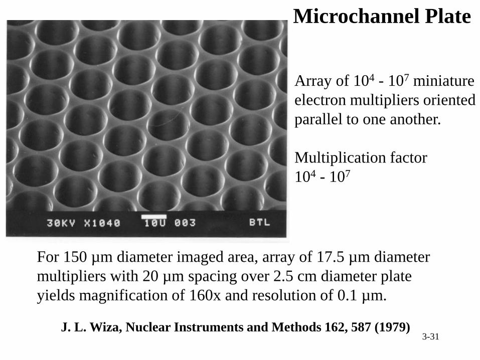
Microchannel Plate
J. L. Wiza, Nuclear Instruments and Methods 162, 587 (1979)
Array of 104 - 107 miniature
electron multipliers oriented
parallel to one another.
Multiplication factor
104 - 107
For 150 µm diameter imaged area, array of 17.5 µm diameter
multipliers with 20 µm spacing over 2.5 cm diameter plate
yields magnification of 160x and resolution of 0.1 µm.

3-32
Microchannel Plate - Fluorescent Screen
Microchannel Plate
16 µm, 8°, 300 - 1200 V
1.2 mm, 5 kV

3-33
CAMECA IMS-3f
J. M. Gourgot, CAMECA
News, No. 2, CAMECA
S. A., Courbevoie,
France (1977)
Magnetic sector analyzer

3-34
CAMECA IMS 6f
Magnetic sector analyzer

Ground Voltage
Impact Energy Sample
Accelerating Voltage
+ 4.0 kV
Extraction Voltage
- 3.0 kV
Conventional magnetic sector SIMS
Primary Column
7 keV
D. Giubertoni et al., FBK
Primary Column: Impact Energy

CAMECA Sc-ULTRA
Sample Ground Voltage
Accelerating Voltage
+ 4.0 kV Impact Energy
Extraction Voltage
- 3.0 kV
Floating Voltage
- 6.0 kV
1 keV
Primary Column: Impact Energy
D. Giubertoni, et al., FBK

TOF-SIMS
ION TOF V

3-38
TOF-SIMS
Physical Electronics
3-39
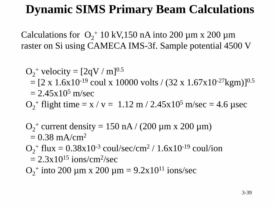
Dynamic SIMS Primary Beam Calculations
Calculations for O2+ 10 kV,150 nA into 200 µm x 200 µm
raster on Si using CAMECA IMS-3f. Sample potential 4500 V
O2+ velocity = [2qV / m]0.5
= [2 x 1.6x10-19 coul x 10000 volts / (32 x 1.67x10-27kgm)]0.5
= 2.45x10⁵ m/sec
O2+ flight time = x / v = 1.12 m / 2.45x10⁵ m/sec = 4.6 µsec
O2+ current density = 150 nA / (200 µm x 200 µm)
= 0.38 mA/cm2
O2+ flux = 0.38x10⁻³ coul/sec/cm2 / 1.6x10⁻¹⁹ coul/ion
= 2.3x10¹⁵ ions/cm2/sec
O2+ into 200 µm x 200 µm = 9.2x10¹¹ ions/sec

3-40
Dynamic SIMS Analysis Calculations
150 nA primary current on Si, 10-20 nA total secondary ions
before electrostatic analyzer (ESA) (CAMECA IMS-6F)
Si+ velocity = 1.75x10⁵ m/sec
Si+ flight time = 1.72 m / 1.75x10⁵ m/sec = 9.8 µsec
Material removed from 1 µm deep crater
volume = 4x10⁻⁸ cm3
density of Si = 5x10²² atoms/cm3 = 2.33 gm/cm3
Si removed = density / volume = 2x10¹⁵ atoms = 93 ngm
Detected area = 60 µm diameter circle
volume = 2.83x10⁻⁹ cm3
Si removed = 1.4x10¹⁴ atoms = 6.6 ngm
Ratio of detected volume to crater volume = 1 / 14