no man entry tank cleaning’ and ‘voc control’ using ... · topics of presentation • a...
TRANSCRIPT

Idrabel Italia S.r.l.Environmental Technologies for Refineries
Prof. Dr. Ibrahim Banat, BSc PhD CBiol FIBiol Professor of Biotechnology, University of Ulster, UK.
Dr. Ivo Rancich, Idrabel Italia, Genoa, Italy.
No man Entry Tank Cleaning’ and ‘VOC Control’ Using
Biotechnological Interventions

Topics of presentationTopics of presentation• A flexible biotechnological "no man entry" tank
cleaning technology. • Adaptation of "no man entry" systems for desludging
damaged tanks. • Application of biotechnological VOC emission tank
control system and its advantages. • Case histories of achievements for the "no man entry"
BioRecOilTM technology & VOC control.

Sludge accumulationSludge accumulation
Sludge accumulates in storage tanks due to slow sedimentation of high gravity petroleum products. Leading to:
• Loss of operational capacity
• Loss of working time• Acceleration of corrosion
in the storage tanks.

Biological based technologyBiological based technology
Idrabel developed a biotechnological automated system that allows recovering ≥
95% of the
hydrocarbons present in the sludge & minimizing waste to be treated or ‘safely’ disposed of.
BioRecOilBioRecOil™™ ProcessProcess
Patent n. EPPatent n. EP1427547 e E0662041427547 e E066204
Biosurfactants

Access Access throughthrough manholesmanholes
Rotating modules are installed on the manholes opening using the Cold tap technique.
No welding and heating.

Pumps access
The modules are connected to large pumps installed in the basin
of the tank
to allow circulation.

Sludge mappingSludge mappingIdrabel also developed a sludge mapping modelling
system, using thermographic measurements to determine sludge volume & distribution in tanks
Oil
Sludge
Water

3 D mapping data modelling3 D mapping data modelling
Mapping output
Topographical Profile

BioRecOilBioRecOilTM TM ProcessProcess
Oil
Sludge, sand and gravel)
Manhole
• Fluxing oil (crude or gasoil), water & biosurfactant
are added• Circulation complete & separation of phases achieved• Recovery processes to be followed
AfterBefore
Oil
circulation circu
lation

VOC Control SystemVOC Control System
• Idrabel also developed a VOC control system• The System uses biotechnological and chemical products
(LECS)
• A spray atomization system
is installed around the tank with lines provided with nozzles, and adjustable sprinklers sprays using a
limited
quantity of fire-water
containing the product.

VolumeDiameter ProductSludge vol. Composition
90,000 m3
76 m – floating roofCrude oil (quantity approx. 30,000 m3)3,000 m3
~ 95 % hydrocarbons
Main problems related to the tank
the floating roof is damaged, sunk & unusable the roof legs cannot be repositioned the gasket seals compromised in part exposed vapour-space exist between roof and oil the pontoons of the roof were flooded with crude the crude has an high H2 S content important leakages present at the tank bottom water was introduced to avoid crude oil loss
““No man entryNo man entry”” case history 1case history 1

Damaged Roof top

““No man entryNo man entry”” case history 1case history 1
Objectives
Recover all oil in the tank (pumpable, not pumpable and sludge).
Safe demolition of the roof.
Minimize sludge volume
Process description
BioRecOilBioRecOil™™ ProcessProcess stared installing 3 telescopic modules through manholes.
crude oil contained in the tank was used as fluxing oil.
2 circulation phases were carried out.

Mobilisation

Operational steps
Collection and interpretation of thermometric data using the SW Sludge Viewer.
Increasing safety and elimination of explosion risk through installation and use of a VOC nebulizing
system on top of the roof
Gas monitoring detection systems (internal and external)

Process description
Installation of BioRecOil equipment for sludge fluidizing
Extraction of oil/water and Oil Recovery
2nd fluidizing phase and water washing drainage &
discharge using hot water and oil/water/sludge

Continue Process description
Degassing and monitoring
Blanketing and foam spraying in the cold cutting areas for opening the tank shell
Washing and progressive blanketing of pontoons
from the external part

Cold holes cutting of pontoons to measure internal explosion values and HP washing using specific product to eliminate explosion risk
Progressive cutting of the roof with shears while localized spraying of LECS product under continuous monitoring
Distribution of a foam layer on the bottom of the tank to increase safety
All demolition devices were equipped with an LEL detector connected to a control station
Continue Process description
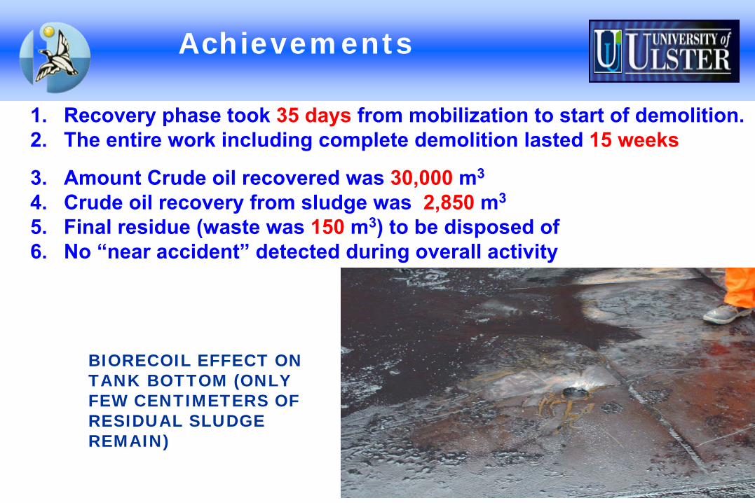
Achievements
1. Recovery phase took 35 days
from mobilization to start of demolition.
2. The entire work including complete demolition lasted 15 weeks
3. Amount Crude oil recovered was 30,000
m3
4. Crude oil recovery from sludge was 2,850
m3
5. Final residue (waste was 150
m3) to be disposed of
6. No “near accident”
detected during overall activity
BIORECOIL EFFECT ON TANK BOTTOM (ONLY FEW CENTIMETERS OF RESIDUAL SLUDGE REMAIN)

Other cleaned tanks

Case History 2
VolumeDiameter Product
65,000 m3
61m –
floating roofCrude Oil
Sludge amount
9700 m3
: quantified by thermographic imaging and manual depth measurements
Main problems related to the tank
high sludge quantity prevented proper use of the tank (handling & unloading activities)
the tank remained in service because it was equipped with a floating
suction facility
the roof runs the risk of sinking in the sludge
risk of sending sludge to the pipeline during transfer activities
loss of tank capacity (20,000 m3)

Tank and sludge level
Sludge profiling
Thermographic imagingTank farm areal view

Process and Achievements
Process descriptionIn service cleaning
3 telescopic modules were installed on the tank shell through existing manholes
crude oil in the tank was used as fluxing oil
biosurfactants were loaded into the tank and
circulation was carried out
Work duration
The work lasted 30 days
including mobilization and demobilization
During the BioRecOil®
Process the tank was kept in service all the time
Achieved results
Tank remained out of operation only for 130h
during the circulation phase
Hydrocarbons recovery (8000 m3) ≈
90% of
bottom sludge reduction
Tank capacity almost totally recovered (sludge reduced to less than 20cm
height)

Case History 3 VOC
Problem detected
VOC emissions in an oil storage farm connected to the largest Western European inland oil field caused bad odors release
Sources of emissions were two tanks with floating roof (containing high sulfur compound) and a nearby water treatment basin
Problems with the local community.
Causes
VOC emissions during loading and unloading turbulence in tanks.
Temperature increasing vapors release
Wind acting as an extraction factor

Possible intervention options
A- Reduction and uptake of bad smell emissions:
Site covering,
Entrapping emissions and directing to an external treatment system for strip washing,
Use of absorbing Columns.
B- Use of biotechnological substances capable of reduction of bad odor emissions:
Installation of VOC Control
System on top of the
tank controlling VOC emissions through nozzles nebulizing LECS product over emission points

ESTIMATED INVESTMENT COSTS
OPTION ACost (€) excluding VAT
Coverage of each
floating roof tank 458,000.00Coverage of water treatment basin 26,500.00Collection & reduction VOC emissions System 461,800.00
OPTION BVOC Control System for each
tank 10,000.00
LECS product for each tank 8,000.00 €/monthVOC Control System for water treatment basin 8,000.00LECS product 5,000.00 €/month

VOC control system on roof top
LEL total reduction on the floating roof
VOC control system
Operational VOC control system on floating tank roof

Wireless monitoring system and Station with supplies
Box with 4 dosage system & 1 tank
213
3 3
PCPORTABLE MULTIGASDETECTOR
MODEM EXSTENDING DETECTION RANGE

VOC Sensors and detectors
Sensor probe connected to the multigas portable detector
Portable multigas detector on shell of tank roof
Detect VOC, Gas, LEL

CONCLUSIONS
Option AAlthough
Radical technology that almost eliminates the source of odor emissions
Technology accredited by years of experience
Yet
Involves a long period of down-time to cover areas and installation of an emissions collection system and to
provide a treatment system for collected emissions
It involves ambitious programme from a technical and economical point of view

CONCLUSIONS
Option B in comparison
Minimal construction and installation impact.
Investment needs are kept at minimum.
Has a high efficiency in totally reducing VOC emissions.

For further information
The endThe end
IDRABEL Italia S.r.l.Tel. 010/9131029 Fax. 010/9131022
e-mail : [email protected] sit : www.idrabel.it