no. ipc irc description - icc | international code council no. ipc irc description 1 312.1(2)...
TRANSCRIPT

4
2
3
1
MAX 24"
MAX 30"
MATERIALSTraps
YOU SHOULD KNOW: IPC 908.1, 1002.5 AND IRC P3201.7
• IPC 908.1, IRC P3107.1: An individual vent is permitted to vent two traps or trapped fi xtures as a common vent.
• IPC 1002.5, IRC P3201.7 & TABLE P3201.7: Fixture trap size shall be suffi cient to drain the fi xture rapidly and not less than the size located in Table 709.1.
For additional resources visit www.code-ref.com 7
TRAPS
No. IPC IRC Description
1 1002.1 P3201.6 Vertical distance from fi xture to the trap weir can not exceed 24".
2 1002.1 P3201.6Horizontal distance from the fi xture outlet to the centerline of the trap inlet can not exceed 30".
3 1002.4 P3201.2Each fi xture trap must have a liquid seal of not less than 2" and not more than 4".
4 1002.1 (2) P3201.6Exc. 2
Combination plumbing fi xture can share a trap as long as one compartment is not more than 6" deeper than the other compartment and compartment outlets are 30" or less apart.

PERMITS AND INSPECTION
PERMITS (IRC R105 • IPC 106)
REQUIRED (IRC R 105.1 • IPC 106.1)
• Construction, alteration, removal, or repair of any plumbing system.
APPLICATION (IRC R105.3 • IPC 106.3)
• Submit application to local building department.
• Submit two or more sets of all supporting construction documents.
• Code offi cial can waive the requirement for submitting supporting construction documents.
VALIDITY ENFORCEMENT (IRC R105.4 • IPC 106.5.2)
• Code offi cial has the right to enter the premises to make inspections
• Code offi cial is to enforce the code and act on any relative questions
• Code offi cial must carry proper identifi cation when performing his duty
12 www.dewalt.com/guides
• Typically issued for a period of 180 days.
• Time extensions can be granted for up to 180 days.
• May be revoked or suspended if false information was provided on the application.
ISSUANCE (IRC R105.3.2, IRC 105.6 • IPC 106.5)

PERMITS AND INSPECTION
NOT REQUIRED (IRC R105.2 • IPC 106.2)
• Maintenance such as repairing leaks to any plumbing system as long as a replacement is not necessary.
• Removal and reinstallation of water closets.
CODE COMPLIANCE FOR EXEMPT WORK (IRC R102.2 • IPC 106.2)
• Although an inspection will not be performed, you are required to follow codes.
INSPECTIONS (IRC R109.1 • IPC 107)
Underground (IRC R109.1.1 • IPC 107.1)• Made after trenches or ditches are excavated and bedded,
piping is installed, and before backfi ll is placed.
Rough-In (IRC R109.1.2 • IPC 107.1)• Prior to installation of drywall but after the roof, framing,
fi re-blocking, fi re-stopping, draft-stopping, and bracing is in place and all sanitary, storm, and water distribution piping is roughed-in.
Final (IRC R109.1.6 • IPC 107.1)• After the building is complete and when all fi xtures are in
place and ready for use.
For additional resources visit www.code-ref.com 13

GAUGES
No. IPC IRC Description
1 312.1(2)P2503.8
#2
Use a gauge having increments of 1 psi or less for tests requiring a pressure greater than 10 psi but less than or equal to 100 psi.
2 312.1(3)P2503.8
#3
Use a gauge having increments of 2 psi or less for tests requiring a pressure greater than 100 psi.
3 312.1(1)P2503.8
#1
Use a gauge having increments of 0.10 psi or less for tests requiring a pressure of 10 lbs. per square inch or less.
TESTING PROCEDURESGauges
1
2
3
YOU SHOULD KNOW: IPC 312 AND IRC P2503.3
• The permit holder is responsible for required testing.
20 www.dewalt.com/guides

BATHROOMMinimum Code Requirements – IPC 405.3.1 and IRC 307.2
22 www.dewalt.com/guides
21"
24"
4" Min. 4" Min. 4" Min.
Clearance in front of fixtures –at least 21"
IRC
IRCIRCIRC

YOU SHOULD KNOW:
• IPC 910.2 & IRC 3109.3: Offsets are not allowed in waste stack vents between the lowest fi xture drain and the highest fi xture drain. NOTE: Waste stack vents shall not receive discharge from water closets or urinals.
• IPC 909 & IRC 3108.1: Horizontal wet vents, those drainage pipes that serve as both drain and vent purposes, are allowed for any combination of fi xtures within two bathroom groups located on the same fl oor.
BATHROOMVent and Drain Options
1
23
Lavatory
Water ClosetFlange
BathtubBuilding Drain
24 www.dewalt.com/guides
VENT AND DRAIN OPTIONS
No. IPC IRC Description
1 906.1 3105.1Allowable distance of the trap from the vent is based on the pipe size. (See Table on page 64)
2 903.1 3107.1
A vent system serving each building drain must have at least one pipe that extends to the outdoors. (See additional requirements on page 26)
3 908.1 3107.1
An individual vent is allowed to vent two traps or trapped fi xtures. (See additional requirements in the IPC Section 908/909 and IRC 3107 and 3108)

2" or smaller fi xturedrains only
2" or smaller fi xture drains only
2" or smaller fi xture drains or 3" or larger
BATHROOMDrain Pipes
For additional resources visit www.code-ref.com 25
2" or smaller fi xture drains only
DRAIN PIPES – IPC 706.3 & IRC 3005.1
Fitting Type Horizontal to Vertical
Vertical to Horizontal
Horizontal to Horizontal
Sixteenth Bend(22.5°)
Eighth Bend(45°)
Sixth Bend(60°)
Quarter Bend(90°)
Short Sweep
Long Sweep
Sanitary Tee
Wye
Combo Wye and 1/8 Bend
Fittings must be oriented to guide the fl ow of drainage.

3
1
2
5 Minimum 6"
BATHROOMVent Termination
26 www.dewalt.com/guides
4
VENT TERMINATION
No. IPC IRC Description
1 — 3103.1
Open vent pipes must extend at least 6" above the roof or anticipated snow accumulation level (whichever is greater).
2 904.1 3103.1
If a roof is used for any purpose other than weather protection (such as a deck), the vent must extend at least 7' above the roof.
3 904.5 3103.5
Vents can not terminate directly beneath doors, windows or other air intake openings of the building or adjacent buildings.
4 904.5 3103.5Vents that terminate within 4' – 10' horizontally of a door or window must extend at least 2' above such opening.
5 — 3114.4Air Admittance Valves that terminate in the attic must be extended at least 6" above the insulation level.
BATHROOMCleanouts
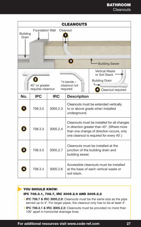
YOU SHOULD KNOW:
IPC 708.3.1, 708.7, IRC 3005.2.9 AND 3005.2.2
• IPC 708.7 & IRC 3005.2.9: Cleanouts must be the same size as the pipe served up to 4". For larger pipes, the cleanout only has to be at least 4".
• IPC 708.3.1 & IRC 3005.2.2: Cleanouts must be provided no more than 100' apart in horizontal drainage lines.
3
Building Drain
Foundation Wall
Building Sewer
4 Cleanout required
Vertical Waste or Soil Stack
45° or greater requires cleanout
21/8 bends –cleanout notrequired
For additional resources visit www.code-ref.com 27
Building Drain
Cleanout
1
CLEANOUTS
No. IPC IRC Description
1 708.3.5 3005.2.3Cleanouts must be extended vertically to or above grade when installed underground.
2 708.3.3 3005.2.4
Cleanouts must be installed for all changes in direction greater than 45°. (Where more than one change of direction occurs, only one cleanout is required for every 40'.)
3 708.3.5 3005.2.7Cleanouts must be installed at the junction of the building drain and building sewer.
4 708.3.4 3005.2.6Accessible cleanouts must be installed at the base of each vertical waste or soil stack.

BATHROOMWater Piping – Hot and Cold Water Lines
4
1
3
2
6"– 8"
19"– 22"
1
5
28 www.dewalt.com/guides
WATER PIPING – HOT AND COLD WATER LINES
No. IPC IRC Description
1 Table604.5
Table2904.5
Approved water distribution pipe includes CPVC, PEX, and copper. A complete list of approved material can be found as referenced.
2 Table604.5
Table2903.7
Water supply line size requirements vary based on the type of fi xture. (See Table on page 66)
3 TypicalInstallation
Lavatory water stub-out should be between 19 and 22" from the fl oor.
4 TypicalInstallation
Space between hot and cold water stub-out for lavatory should be between 6 and 8".
5 305.8 2603.2.1Shield plates must be installed to protect pipes if the whole bored for installation is closer than 1.5” from nearest edge.

Overfl ow tube
Flapper
Toiletbowl
Integraltrap
Main drain
Flange
Toiletlever
Float cup/sensor
Fill Valve
WaterSupply
Shut offvalve
Vent
Flush valve
IRC P2712.4Min. 1" to criticallevel of fill valve
BATHROOMWater Closet
Wax seal
For additional resources visit www.code-ref.com 29
WATER CLOSET
IPC IRC Description
425 2712
Water closets are manufactured per code standards and will be in compliance with sections 425 of the IPC and 2712 of the IRC.

BATHROOMBathtub
YOU SHOULD KNOW: IPC 405.8 AND IRC 2704.1
• Slip joint type P-Traps can only be used if an access panel or utility space of at least a 12" dimension is provided.
1
2
3
4
32 www.dewalt.com/guides
BATHTUB
No. IPC IRC Description
1 407.2 2713.1Drain outlet of at least 11/2" is required with an approved waste stopper.
2 Table709.1
Table3201.7
Trap size must be at least 11/2". (See Table on page 67)
3 Table604.5
Table2903.7
Hot and cold water supply must be at least 1/2". (See Table on page 66)
4 Table604.5
2708.21/2" riser to the shower head is required and must be attached to the structure.

HYDROMASSAGE BATHTUB
No. IPC IRC Description
1 407.2 2713.1Minimum outlet must be at least 11/2" diameter.
2 Table709.1
Table3201.7
P-Trap must be at least 11/2".(See Table on page 67)
3 405.7.1 —Overfl ow must discharge into the drainage system.
4 421.5 P2720.1
Access door must be provided for pump maintenance and must be of adequate size to allow removal.
Access door must be at least 12" � 12". In cases where the pump is more than 2' from the opening, the access must be 18" � 18".
4
1
2
3
BATHROOMHydromassage Bathtub
YOU SHOULD KNOW: IPC 421.2
• Hydromassage bathtubs must be installed with the manufacturer’s instructions and tested in accordance to the manufacturer.
For additional resources visit www.code-ref.com 33

4
7
3
2
5
6
1
MIN 18"MAX 42"
UTILITY ROOMAutomatic Washing Machine
34 www.dewalt.com/guides
AUTOMATIC WASHING MACHINE
No. IPC IRC Description
1 406.3Table
3201.7Trap and fi xture drains must be at least 2".
2 406.3 3005.4Fixture drain must connect to a horizontal drain or drainage stack that is at least 3" diameter.
3 406.3 2718.1Waste water must be discharged through an air break into a standpipe.
4 Table604.5
Table2903.7 Water supply must be at least 1/2".
5 802.4 3201.6Each standpipe must have an individual trap.
6 802.4 2706.2
Standpipes must be at least 18" above the crown weir but no more than 42". (IRC specifi es at least 30" from standpipe outlet to weir.)
7 916.1Table3113 Vent must be at least 11/4"

1
7
2 6
53
4
8
RED – Hot water line from water heater
BLUE – Cold water line from water supply
UTILITY ROOMUtility Sink
For additional resources visit www.code-ref.com 35
UTILITY SINK
No. IPC IRC Description
1415.2418.2
P2715.1Each compartment of a laundry or utility sink shall have a minimum 11/2" drain outlet.
2 608.15.4.2Table
P2902.3
If faucet to be used has hose threads on the spout, it must have either a built-in vacuum breaker or one has to be installed on faucet spout.
3 709.1Table
P2715.1Minimum 11/2" P-Trap.
4Table604.5
TableP2903.7
Hot water line must be a minimum of 1/2".
5Table604.5
TableP2903.7
Cold water line must be a minimum of 1/2".
6 916.1 P3113.1 Vent must be a minimum of 11/4".
7 415.2 P2714.1 Sanitary tee must be a minimum of 11/2".
8 415.2 P2714.1 Drain pipe must be a minimum of 11/2".

2
5
64
1
3
3
3
RED – Hot water line from water heater BLUE – Cold water line from water supply
KITCHENSinks
36 www.dewalt.com/guides
SINKS
No. IPC IRC Description
1 418.2 P2714.1Waste outlets for sinks must be at least 11/2" and feature a strainer or crossbar to restrict the clear opening of the waste outlet.
2 413.2 P2716.1Drain for the garbage disposal must be at least a 11/2" drain outlet.
3 409.3
802.1.6802.1.7
P2717.1P2717.2P2717.3
The waste water from a dishwasher must discharge in one of the following manners:(a) directly through an air gap or air break.(b) discharge into a wye branch fi tting on
the tail piece of a kitchen sink drain or food grinder.
4 604.5 P2903.7Hot water inlet to the dishwasher must be at least 1/2"
5 Table709.1 P2717.3
Dishwasher, disposal, and kitchen sink can share the 11/2" waste drain pipe. (See Table on page 67)
6 604.5 P2903.7Branch lines for hot and cold water must be at least 1/2".

YOU SHOULD KNOW: IPC 917 AND IRC P3114
• IPC 917.2 & IRC 3114.2: Air admittance valves must be installed after the DWV pressure testing.
• IPC 917.8: Prohibited Installations – Air admittance valves can not be located within spaces utilized for return air or for air supply.
• IPC 917.3.3: If vent stacks or stack vents exceed six branch intervals, the stack shall not serve as a drainage vent terminal.
• IPC 917.4: Air admittance valves must be located at least 4" above the fi xture drain.
KITCHENAir Admittance Valve
Air admittance valves are pressure-activated, one-way vents used where outdoor venting is not desired. (Commonly used for island kitchen sinks.) When wastewater discharges, it causes the valve to open, releasing the vacuum and allows the air to enter the vent for proper drainage. Otherwise, the valve remains closed and prohibits the sewer gases to escape to the room.
MIN 4"
For additional resources visit www.code-ref.com 37
HOW IT WORKS – AIR ADMITTANCE VALVE

1
33
4 2
KITCHENIsland Fixture Venting
38 www.dewalt.com/guides
ISLAND FIXTURE VENTING
No. IPC IRC Description
1 913.1 3112.1
Island fi xture venting is not allowed for fi xtures other than sinks and lavatories. Such fi xtures are permitted with a dishwasher waste connection, a food waste grinder or both.
2 913.2 3112.2
Island vents must extend vertically above the drainage outlet of the fi xture being vented before offsetting (vertically or horizontally)
3 913.3 3112.3
Cleanouts must be provided in the island fi xture vent to permit rodding of all vent piping located below the fl ood level rim of the fi xtures.
4 917.3 3114.4Air admittance valves are allowed for the purpose of venting island fi xtures.

WATER HEATERSAttic Installation
YOU SHOULD KNOW:
• When pipes are exposed in an unheated space, insulation and heat source is required to prevent freezing.
6
4
2
3
5
For additional resources visit www.code-ref.com 39
1
ATTIC INSTALLATION
No. IPC IRC Description
1 501.4 M1305.1.3Water heaters must always be installed in locations feasible for observation, maintenance, and replacement.
2 502.3 M1305.1.3 Access must be at least 20" � 30" or large enough for removal of water heater.
3 502.3 M1305.1.3 Access can be no more than 20' from the water heater.
4 502.3 M1305.1.3 The path to the water heater must be solid fl ooring no less than 24" wide.
5 502.3 M1305.1.3A level work area (service space) at least 30" � 30" must be provided in front of the water heater.
6 504.6 P2801.5.2
Required: Pan with drain that runs to the exterior of the building terminating no less than 6" and not more than 24" from the ground.

WATER HEATERSTankless Water Heater
A B
E
E
YOU SHOULD KNOW
• Water heaters must be installed in compliance with Chapter 28 of the IRC and Chapter 5 of the IPC. NOTE: All water heaters must be installed in accordance with the manufacturer’s installation instructions.
44 www.dewalt.com/guides
TANKLESS WATER HEATER
HOW IT WORKS
Ltr. Step
A Step 1: Fixture hot water valve is turned on.
B Step 2: Water fl ows through the heater.
C Step 3: Water fl ow activates burner control.
D Step 4: Burner is ignited.
E Step 5: Heat exchanger heats the water as water fl ows through.
F Step 6: Burner adjusts to heat the water to the specifi ed temperature.
G Step 7: When the fi xture burner shuts down, water fl ow is turned off.

SILL COCKS
YOU SHOULD KNOW
• The shank of the sill cock faucet extends into the wall or crawl space 6" – 14". This makes the faucet “freeze-proof”. If a garden hose is left connected to the faucet in the winter, the faucet may freeze.
• Garden hoses are the number one cause for cross connection backfl ows; causing contamination of our drinking water.
Hose BibbHose Connection Vacuum Breaker
2
Sill Cock
2
1
48 www.dewalt.com/guides
1
SILL COCKS
No. IPC IRC Description
1 608.15.4.2 P2902.4.3
All sill cocks, hose bibbs, wall hydrants, and other openings with a hose connection must be protected by an atmospheric-type vacuum breaker, pressure-type vacuum breaker, or a permanently attached hose connection vacuum breaker.Exceptions: water heater boiler drain and hose bibbs for washing machines.
2 202 R202
Vacuum Breaker – An anti-siphon device that prevents waste water from being drawn back into supply lines, potentially contaminating the water supply.

BACKFLOW PREVENTIONAir Gap
Air gap is a means of preventing backfl ow.
1
UnderneathSalad Bar
Sink
Air Gap
4
5
6
3
1
2
AIR GAP
No. IPC IRC Description
1 202 R202
Air Gap (Drainage System) – The unobstructed vertical distance through the free atmosphere between the outlet of the waste pipe and the fl ood rim of the receptacle into which the waste pipe is discharged.
2 202 R202
Air Gap (Water Distribution System)– The unobstructed vertical distance through the free atmosphere between the lowest opening from any pipe or faucet supplying water to a tank, plumbing fi xture, or other device and the fl ood level rim of the receptacle.
3 202 R202 Indirect/Waste pipe.
4 202 — Diameter of the pipe.
5 802.2.1 P2902.3.1
Distance of the air gap is determined by multiplying the diameter of the pipe times two. Minimum 1". (i.e.: A pipe with a 2" diameter would need a minimum of a 4" air gap)
6 — — Waste receptor such as a fl oor sink.
For additional resources visit www.code-ref.com 49

ISOMETRICSCommercial Restrooms
1
4
3
4 4 4
34
1
2
To size the Horizontal Branch Drain Sizing, calculate the total DFUs fi rst.
TABLE 709.1: DRAINAGE FIXTURE UNITS FOR FIXTURES AND GROUPS
Fixture TypeDFU Value As Load Factors
Minimum Size of Trap
Automatic clothes washers, commerciala,g 3 2Automatic clothes washers, residentialg 2 2Bathroom group as defi ned in Section 202 (1.6 gpf water closet)f 5 —
Bathroom group as defi ned in section 202 (water closet fl ushing greater than 1.6 gpf)f 6 —
Bathtubb (with or without overhead shower or whirlpool attachments) 2 11/2
Bidet 1 11/4Combination sink and tray 2 11/2Dental lavatory 1 11/4Dental unit or cuspidor 1 11/4Dishwashing machinec, domestic 2 11/2Drinking fountain 1/2 11/4Emergency fl oor drain 0 2Floor drains 2 2Kitchen sink, domestic 2 11/2Kitchen sink, domestic with food waste grinder and/or dishwasher 2 11/2
Laundry Tray (1 or 2 compartments) 2 11/2Lavatory 1 11/4Shower 2 11/2Service sink 2 11/2Sink 2 11/2Urinal 4 NotedUrinal, 1 gallon per fl ush or less 2e NotedUrinal, nonwater supplied 0.5 NotedWash sink (circular or multiple) each set of faucets 2 11/2Water closet, fl ushommeter tank, public or private 4e NotedWater closet, private (1.6 gpf) 3e NotedWater closet, private (fl ushing greater than 1.6 gpf) 4e NotedWater closet, public (1.6 gpf) 4e NotedWater closet, public (fl ushing greater than 1.6 gpf) 6e Noted
1
2
3
4
Multiply the quantity by the DFU value to determine the total.
DFU CALCULATIONS
No. Fixture Qty. DFU Total
1 Floor Drain 2 0 0
2 Lavatories 4 1 4
3 Urinals 2 4 8
4 Water Closet 6 4 24
Add together = 36 DFUs
See full Table on page 67.
For additional resources visit www.code-ref.com 55

ISOMETRICSCommercial Restrooms
• A horizontal branch is a drainage branch pipe extending laterally from a soil or waste stack or building drain that receives the discharge from two or more fi xture drains or branches and conducts the discharge to the soil or waste stack or to the building drain.
• A branch interval is a vertical measurement of distance, 8 feet or more in developed length between the connections of horizontal branches to a drainage stack.
• A stack is a general term for any vertical line of soil, waste, vent or inside conductor piping that extends through at least one story with or without offsets.
• Size the horizontal branch drain based on the information from page 54.
• Total DFUs from men’s and women’s restrooms is 36. The correct column to use is “Total for horizontal branch.” The diagram is a single story and horizontal branch is not connected to a stack.
• Find the number in column B that will accommodate 36 DFUs. In this case, the 160 DFU value would have to be used.
• Follow that row to the left column: “Diameter of Pipe” which indicate the size of horizontal branch needed.
TABLE 710.1(2): HORIZONTAL FIXTURE BRANCHES AND STACKSa
Diameter of Pipe (inches)
Max. Number of Drainage Fixture Units (DFUs)
Total for horizontal
branch
Stacksb
Total discharge into one
branch interval
Total for stack of three branch intervals or less
Total for stack greater than three branch
intervals
11/2 3 2 4 82 6 6 10 24
21/2 12 9 20 423 20 20 48 724 160 90 240 5005 360 200 540 1,100
See full Table on page 68.
56 www.dewalt.com/guides

2
1
4
3
6
9
10
711
19
18
17
ISOMETRICSCommercial Restrooms
For additional resources visit www.code-ref.com 57
NOTE: This vent pipe is not required by code, but is ok to be installed.
COMMERCIAL RESTROOM ISOMETRICS
No. Description
1The branch drain line having a slope of 1/8" shall be 4" in diameter. A 4" can convey a maximum of 160 DFUs. A total of 36 DFUs were calculated on the previous page.
2 6 4" � 1½" fi xture fi ttings are required for lavatory drainage.
3 7 1½" double fi xture fi ttings are required to convey drainage from back-to-back lavs.
4 1¼" P-Traps for lavs.
9 17 4" � 3" fi xture fi ttings are required for all hung closet and urinal drainage.
10 18 3" single water closet carrier is required for wall hung water closets.
11 19 3" � 2" sanitary tees are required for urinal drain connections.

ISOMETRICSCommercial Restrooms
13
1422
21
15
2528
27
24
58 www.dewalt.com/guides
NOTE: This vent pipe is not required by code, but if installed 28 will require a 4" cleanout with plug with 4 � 2 reducing bushing.
COMMERCIAL RESTROOM ISOMETRICS (cont.)
No. Description
13 4" � 2" fi xture fi ttings is required for drain connection of fl oor drain.
14 2" double fi xture fi ttings or 2" double sanitary tee is re-quired for both fl oor drains.
15 2" fl oor drains shall have trap primers to prevent sewer gases from entering restrooms.
21 24 4" � 3" fi xture fi ttings are required for wall hung water closet drain connection.
22 25 3" double water closet carrier is required for back-to-back wall hung water closets.
27 Two 1/8" bends or one longsweep ¼" bend is required.
28 4" cleanout w/plug.

5
3
147 11
19
8
1216
22
23
20
ISOMETRICSCommercial Restrooms
For additional resources visit www.code-ref.com 59
NOTE: This vent pipe is not required by code, but is ok to be installed.
NOTE: Less than 40' vent length assumed.
COMMERCIAL RESTROOM ISOMETRICS (cont.)
No. Description
5A 1¼" 90º elbow is required to be installed for vent connection. A 1½" � 1¼" bushing or reducer shall be installed on top of fi tting at #3.
8A 1¼" � 1¼" � 1¼" tee is required to be installed for vent connection. A 1½" � 1¼" shall be installed on top of fi tting at #7.
12A 1½" � 1½" � 1¼" tee is required to be installed for vent connection. A 2" � 1¼" bushing or reducer shall be installed on top of the fi tting at #14.
16A 1½" � 1¼" � 1½" tee is required to be installed for vent connection. A 2" � 1¼" bushing or reducer shall be installed on top of the fi tting at #14.
20A 2" � 1½" � 1½" tee is required to be installed for vent connection. A 3" � 1½" bushing or reducer shall be installed on top of the fi tting at #19.
23A 2" � 1½" � 1½" tee is required to be installed for vent connection. A 3" � 1½" bushing or reducer shall be installed on top of fi tting at #22.

ISOMETRICSCommercial Restrooms
26
2528
29
30
YOU SHOULD KNOW
• This is not by scale. Always check with local codes that may apply. The above would be the same if the water closet were fl oor mounted. There would be a difference if the water closets were tank type instead of fl ush valve. Check tables in code book.
60 www.dewalt.com/guides
NOTE: This vent pipe is not required, but if installed, 28 will require a 4" cleanout with plug with reducing bushing, 29 a 2” tee, and 30 a 2” vent.
COMMERCIAL RESTROOM ISOMETRICS (cont.)
No. Description
26A 2" � 2" � 2" tee is required for vent connection. A 3" � 2" bushing or reducer is necessary on top of the fi tting at #25.
29 A 90° EL is required for vent connection.
30 A 2" vent shall be installed to vent all fi xtures through the roof. (Assuming 40 feet or less vent length.)

Lavatories(back to back)
1
2
4
3
4
5
2
5
4
5
3
4
5
3
4
4
4
6
3
4
5 5
4
5
4
5
4
ISOMETRICSCommercial Restrooms – Lavatories
For additional resources visit www.code-ref.com 61
NOTE: Assume sizing for 100 feetdeveloped length and 49 PSIG pressure.
COMMERCIAL RESTROOM ISOMETRICS – LAVATORIES
No. Description
1
3/4" � 1/2" � 1/2" Tee – Upstream there are 6 WSFUs (cold). Using the table, count the value (WSFU) of the different fi xtures that will have hot water.
22" � 11/4" � 1/2" Tee – Upstream there are 76 WSFUs. Using the table, count the value of the different fi xtures that will have cold water.
3 1/2" Tee
4 1/2" 90° Ell
5 1/2" Caps
6 11/4" � 11/4" � 1/2" Tee

ISOMETRICSCommercial Restrooms – Water Closets
13
Ladies Water Closets and Men’s Urinals (back to back)
Water Closets (back to back)
9
8
8
9
12
10
13
1313
12
10
15
14
16
16
16
16
10
15
10
16
16
16
62 www.dewalt.com/guides
COMMERCIAL RESTROOM ISOMETRICS – WATER CLOSETS
No. Description
8 11/4" � 11/4" � 1" Tee
9 1" � 3/4" � 1" Tee
10 1" Cap
11 3/4" Tee
12 3/4" Cap
13 3/4" 90° Ell
14 1 1/4" � 1" � 1" Tee
15 1" Tee
16 1" 90° Ell