n/no co fault code – - bryant r.v. servicesbryantrv.com/docs2/docs/newreset2.pdf · ·...
TRANSCRIPT

www.norcold.com/cda ��N6XX/N8XX ModelsRefrigerator Service Manual
n/no co Fault Code – No cooling detected by the controls
1. Turn OFF the refrigerator.2. Disconnect the following from power board:
a. 12 Vdc positive and negative wires. b. AC power cord. c. Solenoid gas valve wires d. Spark/sense electrode assembly wires.
3. Remove the power board cover.4. Reconnect 12 Vdc positive and negative wire.5. Turn ON the refrigerator.6. Locate Pin 15 on 16-pin connector (P1). Pin 15
is the empty socket to the right of the white/violet wire on the top row. See Figure C.
7. Using an insulated jumper wire, short Pin 15 to the power board ground lug for 10-15 seconds. A clicking sound indicates the controls are reset. See Figure C.
N62X/N82X
LP GASACAUTO
ON
GAS
ON LED flashesoff 5 times, every 3 seconds
Models and indicator displayed.
NO
YES
Check for completion ofcooling cycle after resettingpower board.
NO Cooling unit is good. Recheck forventilation obstructions and leveledoperation.
YES
Check for cooling at finassembly.
"no" "co"code shows before cycle
end?
Coolingdetected?
1. Check for ventilation obstructionsand leveled operation.2. Reset power board as shown infigure and described in procedure.3. Allow unit to operate normally.
1. Replace cooling unit if "no" "co" showsbefore completing a full cooling cycle.2. Reset power board as shown infigure and described in procedure.
DisplayN64X/N84X
Audible
AlarmN61X/N81X
The power board can be reset by jumpering pins on the power board on earlier controls of these refrigerators:
Model Serial No. Manufacture Date
N61/N81 9056491 and lower Before 3/23/2006
N621/N821 9126824 and lower Before 4/11/2006
N623/N823 8970880 and lower Before 3/1/2006
N64/N84 9044283 and lower Before 3/22/2006
N64.3/N84.3 8938727 and lower Before 2/21/2006
8. Turn OFF the refrigerator.9. Turn ON the refrigerator. If "n" or "no co" code
displays, repeat steps 7-9.10. Turn OFF the refrigerator. 11. Disconnect the 12 Vdc power positive and
negative wires from the power board.12. Install the power board cover.13. Reconnect the following to the power board:
a. Spark/sense electrode assembly wire.b. Solenoid gas valve wiresc. AC power cord.d. 12 Vdc positive and negative wires from the
power board.14. Place refrigerator in service.
Power Board Reset Procedure �
NOte
A jumper wire to short Pin 15 to ground can be made from a six inch long insulated 22 AWG wire with a 1/2 inch of insulation stripped from each end.
Figure C – Reset Procedure �.

www.norcold.com/cda�� Refrigerator Service ManualN6XX/N8XX Models
The power board can be reset through the optical display using Procedure 2 on these refrigerators:
Model Serial No. Manufacture Date
N61/N81 Not applicable Not applicable
N621/N821 9126824 and higher After 4/11/2006
N623/N823 8970880 and higher After 3/1/2006
N64/N84 9044283 and higher After 3/22/2006
N64.3/N84.3 8938727 and higher After 2/21/2006
1. Turn OFF the refrigerator.2. Disconnect the following from power board: a. 12 Vdc positive and negative wires. b. AC power cord. c. Spark/sense electrode assembly wires.3. Remove the power board cover.4. Reconnect 12 Vdc positive and negative wire.5. Turn ON the refrigerator. It should be operating
in the Manual AC mode (AC power cord disconnected from the power board).
6. Insert one end of a piece of multi-stranded wire (10 gauge works well) whose insulation is stripped 1/2" on both ends, into the P2-2 opening and hold into place.
7. Place the other end of the multi-stranded wire to ground (metal back panel) and hold it in place for a minimum of 10 seconds.
8. Turn OFF the refrigerator.
Entering the diagnostic mode of operation and then clearing fault history screen 6 resets the no cool error. This procedure is found on page 66.
9. Turn ON the refrigerator. If "n" or "no co" code displays, repeat steps 7-9.
10. Turn OFF the refrigerator. 11. Disconnect the 12 Vdc power positive and
negative wires from the power board.12. Install the power board cover.13. Reconnect the following to the power board:
a. Spark/sense electrode assembly wire.c. AC power cord.c. 12 Vdc positive and negative wires from the
power board.14. Place refrigerator in service.
Procedure 3 pertains to these refrigerators:
Model Serial No. Manufacture Date
N61/N81 9056492 and higher After 3/23/2006
N621/N821 9126825 and higher After 4/11/2006
N623/N823 8970881 and higher After 3/1/2006
N64/N84 9044284 and higher After 3/22/2006
N64.3/N84.3 8938728 and higher After 2/21/2006
Figure D – Reset Procedure �.
P2-2 OpeningPower Board Reset Procedure �
Power Board Reset Procedure �

www.norcold.com/cda6� Refrigerator Service ManualN6XX/N8XX Models
DIAgNOStIC MODe — MODeLS N6�X/N8�X
Diagnostic ModeThe Diagnostic Mode uses nine diagnostic channels, commonly known as "screens", to display "live" inputs, outputs, and fault history. Each screen is identified by a number, which shows in the optical control assembly display. See Figure 45.
The N62X/N82X optical control display uses a single 7-segment LED module to display diagnostic information. Information made up of two letter or numbers display in an alternating sequence. Fault history information, "live" inputs, and outputs, are presented using lighted LED segments. The diagnostic LED segments, if present, displays after the screen number turns off. Diagnostic LED segments identification numbers. See Figure 46.
Figure ��. N6�X0/N8�X Optical Control Assembly.
AC
AUTO
1-COLD
LP GAS
COLDEST-9
TEMPSET
ONOFF
MODE
Display
Accessing the Diagnostic Mode
To access the Diagnostic Mode:
1. Press and hold both the MODE
and TEMPSET
buttons at the same time.
2. Release the MODE
and TEMPSET
as soon as screen
displays.
3. A few seconds later, displays.
Changing Screens
To change screens, Press MODE
the button until the next screen displays.
exiting the Diagnostic Mode
To exit the Diagnostic Mode:
1. Press and hold the MODE
and TEMPSET
buttons at the same time.
2. Release the MODE
and TEMPSET
buttons as soon as the LED segment that represents the selected operation mode appears on the display (AUTO, AC, or LP GAS).
Turning the refrigerator OFF then back ON also exits the Diagnostic Mode
1
2 3
7
4
5 6
Figure 46. Diagnostic LEDs Segments Identification.

www.norcold.com/cda 6�N6XX/N8XX ModelsRefrigerator Service Manual
= 30°F
ScreenNumber
2 Seconds
BlankScreen(2 secondpause)
1 Second
DC voltage high
AC relay stuck closed
Door ajar1
2 3
7
4
5 6
DC voltage low
AC heater failed open
AC mode selectedbut not available
Ignition fault
Flame presentwith gas off
1
2 3
4
5 6
Thermistor failure.
DC heater relay stuck open
DC heater relay stuck closed
Service requirederror (SR) hasoccured
AC voltagehas been high
No cool lockout has occured
Screens and Diagnostic Segments Information
Screen Diagnostic Mode Active
Screen 1 confirms that the Diagnostic Mode is active. A few seconds after the number displays, all LED segments light. See illustration
Screen thermistor Fin temperature
Screen 3 shows the actual fin temperature being sensed by the thermistor. This is not the fresh food cabinet air temperature. The illustration shows 30°F fin temperature as displayed in screen 3.
Press the MODE
button to bring up screen 4.
Screen Stored Fault History
Screen 4 displays stored fault history using lighted LED segments. The illustration provides fault history information and assigned LED segments. If a fault occurred, its assigned LED will light.
Screen Stored Fault History
Screen 5 also displays stored fault history using lighted LED segments. The illustration provides fault history information and assigned LED segments. If a fault occurred, its assigned LED will light.
If the LED segments do not match the illustration, the fault is in the optical control display.
Replacing the optical control assembly should resolve this fault.
Press the MODE
button to bring up screen 2.
Screen LeD Segments Reliability Check
Screen 2 continues to confirm the reliability of the display. The screen should go completely blank after the screen number is displayed.
Press the MODE
button to bring up screen 6.
If an LED segment displays, the fault is in the optical control assembly.
Replacing the optical control assembly should resolve this fault.
Press the MODE
button to bring up screen 3.
Press the MODE
button to bring up screen 5.
www.norcold.com/cda66 Refrigerator Service ManualN6XX/N8XX Models
1
7
4 DC voltage normal
DC voltage higher than 15.4 volts
DC voltage lower than 10.5 volts
1
3
4
5 6
AC heater relay is energized
DC power to divider heater
Gas valve relay is energized
DC power to ignition circuitDC power tolight switch
1
2 3Sensing burner flame
Food compartment light is off and door is closed
Thermistor sensing fin temperature
DC heater relayis energized
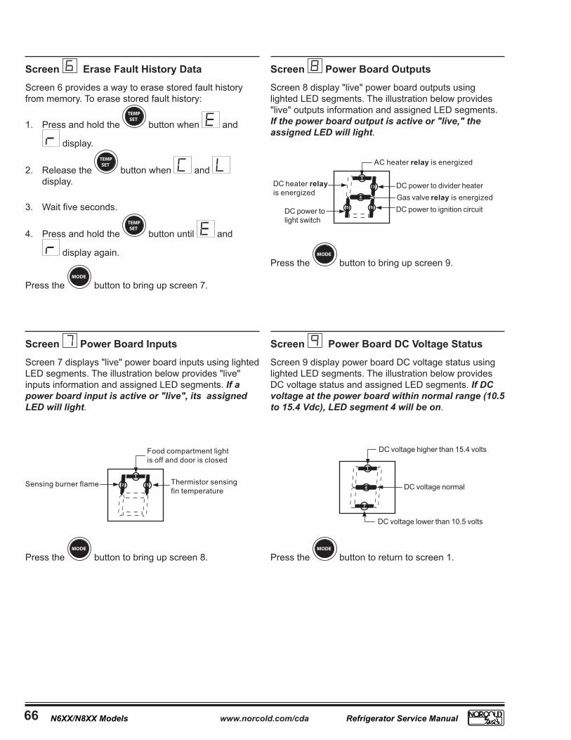
Screen erase Fault History Data
Screen 6 provides a way to erase stored fault history from memory. To erase stored fault history:
1. Press and hold the TEMPSET
button when and
display.
2. Release the TEMPSET
button when and display.
3. Wait five seconds.
4. Press and hold the TEMPSET
button until and
display again.
Press the MODE
button to bring up screen 7.
Screen Power Board DC Voltage Status
Screen 9 display power board DC voltage status using lighted LED segments. The illustration below provides DC voltage status and assigned LED segments. If DC voltage at the power board within normal range (10.5 to 15.4 Vdc), LED segment 4 will be on.
Screen Power Board Inputs
Screen 7 displays "live" power board inputs using lighted LED segments. The illustration below provides "live" inputs information and assigned LED segments. If a power board input is active or "live", its assigned LED will light.
Screen Power Board Outputs
Screen 8 display "live" power board outputs using lighted LED segments. The illustration below provides "live" outputs information and assigned LED segments. If the power board output is active or "live," the assigned LED will light.
Press the MODE
button to bring up screen 8.
Press the MODE
button to bring up screen 9.
Press the MODE
button to return to screen 1.

www.norcold.com/cda 6�N6XX/N8XX ModelsRefrigerator Service Manual
Figure ��. Models N6�X/N8�X Optical Control Assembly.
Diagnostic ModeThe Diagnostic Mode uses ten diagnostic channels, commonly known as "screens", to display "live" inputs, outputs, and fault history. Each screen is identified by a number, which shows in the optical control assembly display. See Figure 47.
The N64X/N84X optical control display uses a dual 7-segment LED module to display the screen number and diagnostic information. Information made up of four letters or digits displays in an alternating sequence. Fault history, "live" inputs, and outputs is presented using LED segments. The diagnostic LED segments, if present, display to the right of the screen number. Diagnostic LED segments identification numbers. See Figure 48.
exiting the Diagnostic Mode
To exit the Diagnostic Mode:
1. Press and hold MODE and TEMPSET buttons at the
same time.
2. Release the MODE and TEMPSET buttons as soon as the
display shows .
Turning the refrigerator OFF then back ON also exits the Diagnostic Mode.
DIAgNOStIC MODe — MODeLS N6�X/N8�X
ON TEMPSET
MODE ON-OFF
1-COLD COLDEST-9
Display
Accessing the Diagnostic Mode
To access the Diagnostic Mode:
1. Press and hold both the MODE and TEMPSET buttons at
the same time.
2. Release the MODE and TEMPSET as soon as screen
displays.
3. A few seconds later, displays.
Changing Screens
To change screens, press and hold the MODE button until the next screen displays.
Figure 48. Diagnostic LEDs Segments Identification.
1
2 3
7
4
5 6
ON Light

www.norcold.com/cda68 Refrigerator Service ManualN6XX/N8XX Models
= 32°F
ON Light
Flame present with gas off
1
2
4
5 6
Thermistor failure.
Service Required(Sr) has occured
No cool lockout has occured
AC voltage has been high
3
DC heater relay stuck open*
DC heater relay stuck closed*ScreenNumber
* 3-way models
DC voltage high
AC relay stuck closed
Door ajar
1
2 3
7
4
5 6
DC voltage low
AC heater failed openAC mode selectedbut not available
Ignition fault
ScreenNumber
Screens and Diagnostic Segments Information
Screen erase Fault History
Screen 6 provides a way to erase fault history from memory. To erase fault history:
1. Press and hold the TEMPSET button when shows
on the screen.
2. Release the TEMPSET button when shows on the
screen.3. Wait five seconds.
4. Press and hold the button until show on the screen.
Press the MODE button to bring up screen 7.
Screen LeD Segments Reliability Check
Screen 2 diagnostics continue to confirm the reliability of the display. After a few seconds only the ON light displays. All other LED segments should be off. See illustration.
Screen Diagnostic Mode Active
Screen 1 confirms that the Diagnostic Mode is active. A few seconds after the screen number appears, all LED segments light. See illustration.
Screen thermistor Fin temperature
Screen 3 displays the actual fin temperature being sensed by the thermistor. This is not the fresh food cabinet air temperature. The illustration shows 32°F fin temperature as displayed in screen 3.
Screen Stored Fault History
Screen 4 displays stored fault history using lighted LED segments. The illustration provides fault history information and assigned LED segments . If a fault occurred, its assigned fault history LED will be on.
Screen Stored Fault History
Screen 5 also displays stored fault history using lighted LED segments. The illustration provides fault history information and assigned LED segments . If a fault occurred, its assigned fault history LED will be on.
If the screen segments do not match the ones shown in the illustration, the fault is in the optical control assembly. Replacing the optical control should resolve the fault.
Press the MODE button to bring up screen 2.
The ON light should be the only LED displayed. If any other LED displays, the fault is in the optical control assembly. Replacing the optical control should resolve the fault.
Press the MODE button to bring up screen 4.
Press the MODE button to bring up screen 5.
Press the MODE button to bring up screen 6.
Press the MODE button to bring up screen 3.

3 Publication No. 120803Bwww.norcold.com/cda
Figure 2. Resetting the power board (model N109X power board shown)
Pin 15 GroundJumper Wire