nmfc.engineering.osu.edu · web viewin the meantime, the heat tape that is wrapped on the tube...
TRANSCRIPT

High-temperature High-pressure flow loop
According to manufacturerrsquos guidelines and required policies within the laboratory and university special precautions must be taken when operating equipment or performing procedures within the laboratory The following information includes recommendations for operation and any procedures needed in order to operate equipment within the laboratory This Standard Operating Procedure will be followed along with the requirements of the Chemical Hygiene Plan and Institutional Biosafety Manual
Brief description of operation andor equipment in use The experimental setup is used to study corrosion of metals or release of materials under flowing condition
Attach additional pages as neededBrief Safety Overview
The Principal Investigator is responsible for training employees using the equipment on site The training should include a discussion of the known and potential hazards of material used in conjunction with material an explanation of the relevant policies techniques and procedures including the proper use of personal protective equipment emergencyspill procedures and containment equipment (engineering controls)
Limit access to authorized users Require applicable training
PPE required SkinBody Protection (example Lab Coat) Lab Coat Eye protection Face shield Respirator (example N95) enspenspenspenspensp Hand protection (example Nitrile gloves) enspenspenspenspensp
STANDARD OPERATING PROCEDURE
1 Equipment and supplies11General
A flowing autoclave loop has been designed and used to conduct material corrosion and leaching tests The loop was designed in house and fabricated by Swagelok This document is aimed to provide detailed description of the loop and comprehensive guidance of the test procedure
12PampIDThe PampID of the flowing autoclave is shown in Figure 6-1 A picture of the flowing autoclave system is shown in Figure 6-2
Figure 6-1 PampID of the flowing autoclave system (in Mode 1)
Figure 6-2 Picture of the flowing autoclave system
13EquipmentTable 6-1 Flowing autoclave loop Equipment list from OSU
Name Description Manufacturer Model A1 Autoclave 8 Dia 5 Gal 2 Tri Clover Input 1 NPT
Male Output 316LApache NA (Custom)
CA1
Compressed Air Supply
Building Gas Supply NA NA
FD Flow Diverter 6 Dia 12 Tall 125 semi-eliptoide base 304L
OSU Machine Shop
NA (Custom)
HC1
Heating Coil 1 Tubing Coil Swagelok NA (Custom)
HE1
Heat Exchanger Stainless Steel 16-38 x 4-316 Head Diameter
McMaster-Carr
35185K999
HE2
Upstream Sample Cooler
Square Coiled Tube 2 dia 1 spacing 3 4 OL
NA NA (Custom)
LI Level Indicator PFA Tubing 14 x 0062 Wall Swagelok NA (Custom)PR1
TK1 Pressure Regulator
Building Built-in-Regulator OSU NA
PR2
A1 Pressure Regulator
Building Built-in-Regulator OSU NA
T1 TK 1 Thermocouple Copper-Constantan SS Sheath 18 Dia 12 long
Omega Engineering
TJ36-CPSS-18U-12-SB-SMPW-M
T2 Loop Thermocouple K Type Thermocouple SMP Male Omega Engineering
SA1XL-K-72-SRTC
T3 A1 Thermocouple Copper-Constantan SS Sheath 18 Dia 6 long
Omega Engineering
TJ36-CPSS-18U-6-SB-SMPW-M
T4 LabView A1 Thermocouple
Copper-Constantan SS Sheath 18 Dia 6 long
Omega Engineering
TJ36-CPSS-18U-6-SB-SMPW-M
T5 UFM Thermocouple Self-adhesive T Type Thermocouple 80 molded SMP male
Omega Engineering
SA1XL-T-72
T6 Downstream Loop Cooler
Self-adhesive T Type Thermocouple 80 molded SMP male
Omega Engineering
SA1XL-T-72
T7 Upstream TV1 Self-adhesive T Type Thermocouple 80 molded SMP male
Omega Engineering
SA1XL-T-72
T8 Downstream TK1 Self-adhesive T Type Thermocouple 80 molded SMP male
Omega Engineering
SA1XL-T-72
TK1
Water Storage Tank 12 Dia 10 Gal 1 NPT Male Input 1 NPT Male Output 316L
Apache NA (Custom)
UFM
Ultrasonic Flow Meter Ultrasonic In-line Flow Meter 01-20 ms Micronics PF 330
VSP1
High Flow Variable Speed Pump
1 14 Input 1 14 Output 304 gpm Grundfos CRN 5-9 A-P-G-V-HQQV
VSP2
Low Flow Variable Speed Pump
38 Input 38 Output Fluid Metering Inc
QG400 Q2CSC
NA Pipe Insulation Fiberglass McMaster-Carr
NA
NA Heat Tape 05 x 16 1248W HTS Amptek AWH-052-160D
Table 2 Flowing autoclave loop Equipment list from SwagelokEquip
Name Description Model
CV2 VSP 2 Discharge Check Valve
CHECK VALVE 1PSIG 38 SS-CHS6-1
CV3 TK1 Check Valve CHECK VALVE 1PSIG 1 SS-CHS16-10CV5 FM3 Check Valve CHECK VALVE 1PSIG 38 SS-CHS6-1CV6 HE2 Check Valve CHECK VALVE 1PSIG 34 SS-CHS12-1HC1 Heating Coil Swagelok 1 Tubing Coil NA (Custom)HE3 Downstream Loop Cooler Swagelok Coiled Tube 2 dia 1
spacing 3 4 OLNA
P1 VSP 1 Suction Pressure Gauge
GAUGE 0-100 PSIG PGI-63C-PG100-CBGX-G
P2 VSP 2 Suction Pressure Gauge
GAUGE 0-100 PSIG PGI-63C-PG100-CBGX-G
P3 VSP 1 Discharge Pressure Gauge
GAUGE 0-100 PSIG PGI-63C-PG100-CBGX-G
P4 VSP 2 Discharge Pressure Gauge
GAUGE 0-100 PSIG PGI-63C-PG100-CBGX-G
P5 TK 1 Pressure Gauge GAUGE 0-100 PSIG PGI-63C-PG100-CBGX-G
P6 A1 Pressure Gauge GAUGE 0-100 PSIG PGI-63C-PG100-CBGX-G
P7 UFM Upstream Pressure Gauge
GAUGE 0-100 PSIG PGI-63C-PG100-CBGX-G
P8 UFM Downstream Pressure Gauge
GAUGE 0-100 PSIG PGI-63C-PG100-CBGX-G
RV1 TK 1 Pressure Relief Valve RELIEF VALVE 14 75 PSIG SS-RL3S4RV2 A1 Pressure Relief Valve RELIEF VALVE 14 95 PSIG SS-RL3S4TV1 A1 Bypass Throttle Valve NEEDLE VALVE WITH REGULATING TIP
1SS-12NRS16
TV2 Upstream GSL NEEDLE VALVE 14 SS-1RS4-ATV3 Downstream GSL NEEDLE VALVE 14 SS-1RS4-A
3V1 TK1 SupplyBypass Valve 3-WAY BALL VALVE 1 SS-65XTS16-F163V2 VSP SupplyBypass Valve 3-WAY BALL VALVE 1 SS-65XTS16-F163V3 Flow Meter SupplyBypass
Valve3-WAY BALL VALVE 1 SS-65XTS16-F16
3V4 HE1 SupplyBypass Valve 3-WAY BALL VALVE 1 SS-65XTS16-F16V1 TK1 Air Supply Valve 2 WAY BALL VLV 14 SS-43GS4V2 HE1 Isolation Valve 2 WAY BALL VLV 14 SS-43GS4V4 A1 Air Supply Valve 2 WAY BALL VLV 14 SS-43GS4V5 A1 Supply Valve 2 WAY BALL VLV 14 SS-43GS4V6 System Drain Valve 3-piece 60 Series Ball Valve 1 SS-65TF16V7 A1 Discharge Isolation
Valve2 WAY BALL VLV 14 SS-43GS4
V8 VSP 1 Downstream valve 3-piece 60 Series Ball Valve 1 SS-65TF16V9 FM2 Downstream valve 3-piece 60 Series Ball Valve 1 SS-65TF16V V1 TK1 Vent Valve PURGE VALVE 14 SS-4P-4TV V2 A1 Vent Valve PURGE VALVE 14 SS-4P-4T
14Supplies1) Fisherbrand polypropylene rectangular carboys2) Labware3) Nitrile gloves4) High temperature protection gloves5) Protective eyewear6) Masks7) Safety hats8) Lab coats9) Ice bucket10) Safety hats
15Automation system
An automation system was designed and built for data acquisition and system control on the flowing autoclave loop The data acquisition system is aimed to monitor and store the system parameters including the temperature and flow rate The thermocouples and flow meters are used to measure the system temperature and flow rates The output signals from the thermocouples and flow meters were received by the thermocouple module and current input module respectively A customized LabView configuration was programmed to process these signals and the temperature and flow rate information can be monitored on the computer In addition to the data acquisition system the automation system was also designed to control the system temperature which serves to protect the heat tapes from overheated and maintaining the solution temperature during tests The heat tapes were used to heat up the solution in the flowing autoclave loop Each heat tape was deployed with a k-type thermocouple a stand-alone temperature controller and a contactor A high temperature limit was pre-set on the temperature controller that monitors the temperature on an individual heat tape Once the heat tape is overheated and the temperature exceeds the limit the temperature controller gives out signals to the corresponding contactor and switches off the electrical circuit for providing power to the heat tape The autoclave (A1) and water tank (TK1) was deployed with thermocouples (T1 and T3) which were used to measure the solution temperature in the two vessels Similarly a stand-alone temperature controller and a contactor was used to maintain the solution at the target temperature A full list of the automation system components are summarized in Table 6-3 The junction box and data acquisition system are shown in Figure 6-3
Table 6-3 Automation system component listComponents Vendor Model NumberThermocouples Modules
NI NI9213
Modules Chassis NI NI9174Current Input Modules NI NI9203Temperature Controllers
Auber Instruments
syl-2362
Contactor Honeywell db2040b-1002
T-type Thermocouple Wires
Omega EXPP-T-20-TWSH-SLE-100
K-type Thermocouple Wires
Omega EXPP-K-20-TWSH-SLE-500
K-type TC Connectors Omega UST-K-FT-type TC Connectors Omega USTW-T-FElectrical Wires McMaster Carr Different AWGs
Figure 6-3 Junction box and data acquisition system
2 Operation modesThe four primary Modes of Operation of the OSU test loop are as defined below1) Pre-heat mode
Heat the system and test solution to the desired test temperature2) Solution transferring mode
Transfer of fluid heated in Mode 1 to Autoclave Test configuration Mode 23) Test operation mode
Operate the system under the required test experimental design conditions4) Cool down and sample removal mode
Cool the system solution in preparation for sample removal21Pre-heat mode
It is necessary to raise the temperature and pressure of the water solution to the desired conditions before running the corrosion tests since the water solution with deviating conditions may introduce uncertainties to the results The PampID of the loop during the pre-heat mode is shown in Figure 6-4 Approximately 45 L of the water solution are circulated through the flow path using the high flow pump (VSP1) In the meantime the heat tape that is wrapped on the tube coils will be used to heat the solution in the flow path Compressed air will be introduced into the water tank and autoclave from the instrumentation port to pressurize the loop which is aimed to maintain the water solution subcooled in the loop
Figure 6-4 Flow path in the pre-heat mode (Mode 1)
22Solution transferring modeThis mode is aimed to transfer the solution at target temperature from the water tank to the autoclave for corrosion tests Therefore the corrosion samples can be exposed to the solution at target temperature After the solution transferring mode is complete the water level should be equal to the instrumentation port and the water tank should be bypassed from flow recirculation
23Test operation modeThis flow autoclave loop is used to perform corrosion tests with controlled velocities According to the design inputs tests with different velocities will be conducted For the tests with velocities greater than 005 fts the high flow pump (VSP1) and ultrasonic flow meter (UFM) are used For the tests with velocities lower than 001 fts the low flow pump (VSP2) is used The flow paths for both two velocity tests are shown in Figure 6-5 and Figure 6-6
Figure 6-5 Flow path in the test operation mode (greater than 005 fts)
Figure 6-6 Flow path in the test operation mode (lower than 001 fts)
During the tests ICP samples need to be taken at different time instants Upstream and downstream grab sample line (upstream and downstream GSL) will be separately opened and for collecting ICP samples by adjusting the needle valves
24Cool down and sample removal modeAfter a test is finished the metal sample needs to be pulled out in a relatively short time (typically several minutes) to prevent any further undesired corrosion The flowing autoclave loop needs to be depressurized and sufficiently cooled down to touchable temperature before opening the autoclave and retrieving the metal samples The flow path for the cool down and sample removal mode is shown in Figure 7 The high flow pump VSP1 will be used to recirculate the flow in the loop The loop cooler HE1 will be used to cool down by chilled water provided by the lab In the meantime the bleed valve on the autoclave VV2 is cracked to depressurize the loop The metal samples can be retrieved once the system pressure is atmospheric and the temperature of the solution is touchable
Figure 6-7 Flow path in the cool down and sample removal mode (Mode 4)
3 Pre-test preparationThe following activities should be completed prior to starting the test Verify all necessary supplies (DI water cold air and power supplies) are
available Verify inventory of all chemicals corrosion coupons etc to be used in the
test Verify pH meter is working properly Check the temperature of the hotplate with a calibrated thermometer31 pH calibration
1) Collect 1 L of DI watera Use 500 mL graduated cylinderb Press and hold large dark blue switch on top of the DI water supply to
dispense waterc Check the electrical resistivity of DI water and make sure it is higher
than 175 MΩcm
2) Calibrate analytical balance -- Internal adjustment (see the manual of your balance fordetailed instruction if necessary)a Allow scale to warm up for 1 hour if it was powered offb Remove anything on the balance and use brush to clean the scalec Press and hold weight symbol until you see ldquoADJ INTrdquo d When the scale reads ldquoADJ DONErdquo the internal calibration is completee Check if internal calibration is correct by placing 100 g weight on scale
i If scale does not read 1000000 with plusmn00001 g make sure scale is clean and try an internal calibration again
ii If scale does not read 1000000 within plusmn00001 g then externally calibrate according to Mettler Toledo procedure using 100 g weight
3) Calibrate pH meter before every test (see the manual of your pH meter for more detailed instruction if necessary)f Preparation
i Wash three 100 ml beakers using tap water and soapii Rinse beakers with DI wateriii Dry using Kimwipes
g Calibration of ATC pH probei Pour 50 ml pH = 401 700 and 1001 standards into three
beakers respectively and label the date and person (pH standard solutions should be replaced every month)
ii Turn on the pH meter and hook up the ATC probeiii Loose the black cap before pulling the pH probe out from the
bottleiv Rinse the pH probe with DI water and dry it with Kimwipes Blot
do not rub as this may create staticv Place the ATC pH probe in the pH = 7 standard solution vi Press ldquoCALrdquo and the meter will show ldquoCArdquo (This is the only time
to press CAL in the entire calibration process)vii Keep stirring the standard solution and wait until the pH meter
reads a constant number for at least 2 minutesviii Press ldquoENTERrdquo button to confirm calibration pointix Rinse the probe with DI water and dry it with Kimwipesx Place the probe in the pH = 1001 standard solution xi Keep stirring the standard solution and wait until the pH meter
reads a constant number for at least 2 minutes
xii Press ldquoENTERrdquo button to confirm calibration pointxiii Rinse the probe with DI water and dry it with Kimwipesxiv Place the probe in the pH = 401 standard solution xv Keep stirring the standard solution and wait until the pH meter
reads a constant number for at least 2 minutesxvi Press ldquoENTERrdquo button to confirm calibration point
h Verify the calibrationi Check all the standard solution points with the calibrated probe
rinse the probe with DI water and dry it with Kimwipes place the probe in the pH = 7 standard and stir repeat these two steps with pH = 1001 and 401 standards
ii In the test log record the actual pH readings of three standards from the pH meter include the operatorrsquos name date and time and actual pH readings
iii If any of the three readings is off by more than 003 the calibration needs to start over
iv If with recalibrating the solution pH still differs by more than 01 see troubleshooting guide in Appendix B
i Clean upi Rinse the probe with DI water and dry it with Kimwipesii Insert the probe into the black cap before screw the cap back
onto the bottle (make sure the tip of the probe immersed in the storage solution but does not touch the bottle)
iii Wash all the glassware with tap water and soapiv Rinse them with DI water and dry themv Seal the three standards with parafilm Reminder Standards
must be replaced monthly32Samples preparation
All the samples are cut by the machine shop The detailed dimension information can be found in the sample holder design document [1]
Before putting the samples into the sample holders
a Carve 1 cm mark on the corner of every sample when samples are loaded this corner should point towards test column center and upwards direction
b All the samples need to be labeled and weighed using the scale and the total weight needs to be recorded on the log book
c Pictures of the samples before and after tests need to be taken for all the samples for record and save them in the computer
321 Test with a test column as the test section
1) Loosen the six screws on the top cap of the low velocity sample holder with a 564rdquo allen wrench
2) Insert six coupon samples in the grooves
3) Put the top cap back on and tighten the screws
4) Loosen the six screws on the end cap of the sample holder
5) Insert the sample holder into the test column
6) Stack four sample holder bodies and connect them with dowel pins
7) Tighten the top cap using screws with a 564rdquo allen wrench
8) Align the thread holes on the end cap with the holes at the bottom of the test column
9) Insert the screws from the bottom of the test column and tighten them
The sample holder without and with samples loaded is shown in Figure 6-8
(a) (b) (c) (d)Figure 6-8 a) Four sample holders without samples b) Test column c) Four sample
holders with sample loaded d) Entire assembly
4 Test procedureThe four primary modes of operation of the OSU flowing autoclave loop are as defined below
Mode 1 Pre-heat mode (Figure 6-4)
o Purpose Heat the system and test solution to the desired test temperature
Mode 2 Solution transferring mode (Initial valve positions referred to Figure 6-4)
o Purpose Transfer of fluid heated in Mode 1 to autoclave for test configuration in Mode 3
Mode 3 Test mode (Figure 6-5 and Figure 6-6)
o Purpose Operate the system under the required test experimental design conditions
Mode 4 Cool down and sample removal mode (Figure 6-7)
o Purpose Cool the system solution in preparation for sample removal
Before running the tests the date time test operator test name test contents (samples solutions duration purpose etc) should be recorded on a log book
Table 6-6 Initial system alignment
Component
Initial set point Purpose
TK1 On-lineFluid storage during system heat-up Allow for fluid expansion Provides system overpressure to keep fluid sub-cooled and NPSHa as needed
CA1 with PR1 35 PSIG Provide system overpressure via TK1
CA1 with PR2 35 PSIG Provide system overpressure via A1V1 Open Air supply to TK1V4 Open Air supply to A1
V V1 Closed TK1 Bleed ValveRV1 60 PSIG TK1 Pressure Relief Valve3V2 Aligned to
VSP1 Supply to VSP1VSP2VSP1 Stop Recirculate Solution through heat-up loopV8 Open Allow flow through VSP1
VSP2 Isolated Pump flow for tests with 001 fts velocityV2 Closed HE1 Isolation ValveV3 Closed Sample Valve HE1 ventTV1 Open A1 Bypass ValveTV2 Closed Upstream GSL need valveTV3 Closed Downstream GSL need valveV5 Closed A1 Supply ValveA1 Isolated Autoclave
V V2 Closed A1 Vent ValveRV2 75 PSIG A1 Pressure Relief Valve3V3 Aligned to V9 Supply to UFMV6 Closed System Drain
V7 Closed A1 Discharge IsolationV9 Open valve3V4 Aligned to
System HE1 supply IsolationHE1 Isolated Loop Cooler3V1 Aligned to TK1 TK1 Pump Supply Valve
41Mode 1 Pre-heat and pressurization mode1) System preparation
a Adjust the valve positions shown in Figure 6-4 3V1- To water tank 3V2 ndash High flow pump 3V3 ndash High flow meter 3V4 ndash Flow thru V5 and V7 ndash Off TV1 ndash Fully open (counter-clockwise all the way)
b Pour all the 40 L solutions in the water tank with a 4 L clean plastic beaker
c Start VSP1 ldquoHIGH FLOW PUMPrdquo at 30 Hz to mix the flow for 10 minutes d Cover the water tank with the lid and make sure the lid and gasket are
well alignede Seal the water tank with the clamp and tighten the bolts (2 on one side
and 1 on the other side) with a 38rdquo allen wrench and an adjustable wrench There are two nuts for each bolt The smaller nut goes inside and the larger one goes outside Tighten all three sets of bolts and nuts back and forth to make sure all of them are tight
Figure 6-9 Smaller and larger nuts securing the water tank clamp
f Install the sample holderi) Tests using the test column connect the flange of the test column
with flow diverter and the flange underneath the lid with four 58rdquo bolts and nuts connect the plastic hose with the stainless steel tube for downstream grab sample line
ii) Tests using the autoclave slide the autoclave sample holder assembly to the bottom of the autoclave
g Cover the autoclave with the lid and make sure the lid and gasket are well aligned
h Seal the autoclave with the clamp and tighten the bolt with an adjustable wrench
2) System pressurizationa Pressurize the autoclave and water tank by turning on V1 and V4 until
the reading of P5 and P6 reaches 25 psi then turn V1 and V4 off (PR1 and PR2 not used)
Smaller nutsLarger nuts
b Wait for 10 minutes and check the readings on P5 and P6 to see if the pressure drops due to leakage
i) if no move forward to further flow mixingii) if P5 reading drops depressurize the water tank by fully opening the
VV1 loosen the bolt and nut on the lid to take the lid off realign the lid and then repeat step e and f in System Preparation repeat step a and b in System pressurization to check if the leakage still exists
iii) if P6 reading drops depressurize the autoclave by fully opening the VV2 loosen the bolts and nuts on the lid to take the lid off repeat step a and b in System Pressurization until no more leakage is found
3) Further flow mixing this step serves to further mix the solutions with the VSP1 ldquoHIGH FLOW PUMPrdquoa Switch on the DC power supply for the flow meters the digital display
on the flow meters should be on (Figure 6-10)
Figure 6-10 Power supply box and VFD for VSP1 ldquoHIGH FLOW PUMPrdquo
b Open the LabView file named ldquoAutoclave control1rdquo on the computer (ZHANG-W396-04) click ldquoRunrdquo and the front panel is shown as the screenshot below in Figure 6-11
Figure 6-11 Screenshot of the front panel of the DAQ system
c Switch on the electrical box for the pump and press ldquoRunrdquo on the variable frequency drive (VFD) Increase the pump frequency to 45 Hz by pressing the up arrow on the VFD
Personnel performing the procedures listed below need to wear the high temperature proof gloves
4) Pre-heating a Tune down the water tank pressure to 10 psib Plug in the Junction box and the digital display on the temperature
controllers should be on as shown in Figure (HT2-HT6 are the heat tapes on the tube coil which are preset to be 240 C AUTO SOL and HT1 are the autoclave solution temperature and heat tape wrapped around the autoclave which should be set to the target temperature of specific tests) Please find the temperature controller manual in ref [2]
c Switch on power supply for the heat tape in Figure 6-12
Figure 6-12 Power supply box for the heat tapes
d Monitor the solution temperature in the water tank (T3) on the front panel of the DAQ system shown in Figure 6-11
e When the T3 temperature is 3 0C higher than the target temperature tune down the HT2-HT6 temperature to 200 0C
f Move on to Mode 2
Figure 6-13 Junction box picture
42Mode 2 Solution transferring mode Mode 2 needs to be finished in a fast manner typically within 8 minutes so as to keep the temperature on target 3 persons are needed to operate one controls the VSP1 ldquoHIGH FLOW PUMPrdquo while the second one controls the valve positions and takes baseline ICP and the last one takes lab notes The initial valve positions for Mode 2 should be referred back to Figure 6-4
a Person 1 fully open V5 and V7
b Person 2 dial down the pump frequency to 25 Hz
c Person 1 Take baseline ICP Person 1 opens V2 clears 30 mL liquid and then takes 30 mL ICP sample using a 30 mL sample bottle
d Person 1 cracks the bleed valve on the water tank (VV2) Person 1 and 2 need to adjust the opening extent of VV2 and compressed air For 100 0C T3 = 40 psi for 115 0C T3 = 55 psi for 130 0C T3 = 70-75 psi
e At the moment that liquid water comes out from VV2 (the level indicator (Figure 6-14) that hooks with the outlet of VV2) close VV2 Open the needle valve on the upstream GSL until solution comes out for 15 seconds (purging air bubbles in the solution)
Figure 6-14 Level indicator
f Check the water level through the level indicator if the water level is below the instrumentation port repeat steps b and c
g Person 1 opens TV2 and collects liquid with a beaker until continuous liquid (for 100 0C tests) or flashing flow (for 115 or 130 0C) comes out from upstream GSL
h Person 1 bypasses TK1 by switching 3V1 to ldquoflow thrurdquo and depressurizes the TK1 pressure to be 25 psi by opening VV1
i Crack VV2 until no solution comes out
j Minimize the opening of VV2 direct the hose with VV2 to a beaker with water maintain the bubbling rate in the water to be approximately 1 bubblesecond keep the A1 pressure as stated in step c by adjusting the PR2
k Person 3 records all the activities and timing on the test log
43Mode 3 Test mode1) Loop preparation
a Pipe sample holder test for greater than 005 fts (Figure 6-5)b Turn on the large flow pump VSP1 ldquoHIGH FLOW PUMPrdquo adjust the
pump frequency with the VFD until the UFM reads at the target flow rate (214 gpm for 05 fts 042 gpm for 01 fts 021 gpm for 005 fts)
2) Actual test runninga Record the time that test startsb Keep V9 open c Grab solution sample from upstream and downstream GSL for ICP tests
at different time instants (30 mins 1 hr 2 hrs 4 hrs 8hrs and 24 hrs)i Take two 30 mL Nylgene bottles ii Wear high temperature proof glovesiii Open TV2 to release 20 mL solution before taking 30 mL upstream
sample with the first bottle then label the bottle with date time test name location and personnel name
iv Open TV3 to release 30 mL solution before taking 30 mL downstream sample with the second bottle then label the bottle with date time test name location and personnel name
v After the sample grabbing is done measure the water level on the level indicator and record it in the test log
44Mode 4 Cool down and sample removal mode(Valve positions can be referred to Figure 6-7)Switch off the power supply to the heat tapes1) Switch 3V4 from ldquoflow thrurdquo to ldquoloop coolerrdquo2) Adjust the pump frequency to 45 Hz3) Crack VV2 to maintain the autoclave pressure lower than 75 psi (set
pressure on relief valve)4) When the T3 is lower than 100 C open VV2 to fully depressurize the
autoclave5) Fully open the valves for chill water ldquosupplyrdquo and ldquoreturnrdquo lines
6) Monitor AUTO SOL temperature on the temperature controller7) When the temperature on the DAQ system drops to 50 C and the
autoclave pressure drops to 0 take the insulation cap away on the autoclave
8) Stop the pump VSP1 ldquoHIGH FLOW PUMPrdquo45Autoclave draining and sample retrieving
1) Close V5 and V7 to isolate the autoclave2) Turn on V1 and open V6 to purge the solution to the drain from the
autoclave3) Close V6 and repeat step b until no water comes out from V64) Open TV3 to purge the remaining solution in the flow diverter 5) Unscrew the clamps on and above the autoclave lid take off the tube
above the lid unscrew the downstream grab sample line6) for the autoclave sample holder pull the sample holder out directly 2) for
the test column sample holder unscrew the bolts and nuts on the flange7) Reverse the operation steps in Section 33 to take the samples out of the
sample holders8) Rinse all the samples with DI water and acetone and dry them off by
blowing compressed air9) Weigh all the samples and record the total weight on the log book10) Take pictures for all the samples and save pictures on the computera Store the samples in a large size zip lock bag and write down the test
name personnel names date and time on the bag5 Post-test cleanup procedure
1) Draining remaining solution
a Set the valve positions as shown in Figure 6-4 open V5
b Unhook the outlet hose and P2 hose hook the outlet hose with P2 as shown Figure 6-15 switch 3V2 to VSP2 ldquohigh flow pumprdquo (use VSP2 as the flow path)
c Repeat Section 41 1 degh to seal the water tank and autoclave
d Hook V6 with a 30-gal closed drum
e Open V1 and V4 to pressurize the water tank and autoclave to 50 psi
f Crack the drain valve V6 and slowly purge the water out from the loop once the system pressure is 50 psi
g Repeat step e and f until no water comes out from the drain valve
Figure 1 VSP2 hoses
h Switch 3V1 to ldquoflow thrurdquo and repeat g until no water comes out
i Switch 3V2 to ldquolarge pumprdquo and repeat g until no water comes out
j Open V7 and repeat g until no water comes out
k Close V5 and V7 keep the autoclave pressure at 20 psi and open the needle valve for downstream GSL until no solution comes out
l Close V1 V4 and V6
2) Base Washa Make 45L of NaOH solution (Initial valve positions are in Figure 6-4)b Prepare 018g of NaOH dissolve into 1L deionized waterc Transfer 44L of deionized water into the large secondary containerd Transfer 1L prepared NaOH into the large secondary containere Stir the NaOH solution in the large secondary container with a stirring bar and measure the
pH at multiple locations with a calibrated pH meter (Must be below 985 typically around 950) keep stirring until the variation of the pH readings are less than +- 01 (about 10 mins)
f Transfer 40 L NaOH solution to the water tank
g Repeat Section 41 1 degh to seal the water tank and autoclave
h System cleaning process (Turn on the heat tape to accelerate dissolution Identical to Acid WashDI Rinse)
I Stage 1 (Water Tank Level) i Turn on VSP1 ldquohigh flow pumprdquo at 45 Hz
ii Keep the loop running for 2 hoursII Stage 2 (Autoclave high flow)
iii TV1 Closediv V5 Openv V7 Open
i Drain Solution repeat Section 50 A 3) Acid Wash (Initial valve positions are in Figure 6-4)
a Make 45L of acid solution such as boric acid if the test solution is borated solution (hotplate needed)
b Prepare 657g of H 3BO3
c Keep adding H 3BO3 into 4L beaker on a hotplate with stirring rod until precipitates are observed
d Transfer prepared 4L of diluted H 3BO3 into the large secondary containere Repeat Step 3-4 at least 6 times Avoid putting any H 3BO3(s) into the final solution f Transfer deionized water into the large secondary container until there is 45L total (45-
46=21)g Test the pH of the solution with a calibrated pH meter (Must be above 415 typically around
43-46)h Transfer 40 L H3BO3 solution to the water tank
i Repeat Section 41 1 degh to seal the water tank and autoclave
j System cleaning process (Turn on the heat tape to accelerate dissolution Identical to Acid WashDI Rinse)
I Stage 1 (Water Tank Level) i Turn on VSP1 ldquoHIGH FLOW PUMPrdquo at 45 Hz
ii Keep the loop running for 2 hoursII Stage 2 (Autoclave high flow)
iii TV1 Closediv V5 Openv V7 Open
k Drain Solution repeat Section 50 A
4) DI Rinse (the same procedure as base wash)a Take water sample ( Measure amp Record turbidity and Conductivity in the test log)b Transfer 40 L DI water into the autoclave
c Repeat Section 41 1 degh to seal the water tank and autoclave
d System cleaning process (Turn on the heat tape to accelerate dissolution Identical to Acid WashDI Rinse)
I Stage 1 (Water Tank Level)
i Turn on VSP1 ldquoHIGH FLOW PUMPrdquo at 45 Hzii Keep the loop running for 2 hours
II Stage 2 (Autoclave high flow) iii TV1 Closediv V5 Openv V7 Open
e Drain Solution repeat Section 50 A
5) Loop drying (optional)b TV1 openc 3V1 To water tankd 3V2 To high flow pumpe 3V3 To high flow meterf 3V4 To flow thrug V5 V6 and V7 openh Open V1 and V4 to introduce compressed air into the loop for overnight
Large flow pump operation instructions1 Operation conditions
The large flow pump (VSP1) has restrict requirements on the conditions up which it is running All these requirements should be rigorously to prevent potential damage to the pump
Temperature pumps with Cool-Top ndash up to 356 F (180 C) when the operating temperature is higher than 266 F (130 C) the minimum flow rate should be higher than 25 gpm which is 10 of the flow capacity of the pump
Minimum inlet pressure (NPSHR)+2 ft
Maximum operation pressure 232 psi
Material compatibility see manuals for detailed information
Liquid level check The pump CANNOT run without being filled with liquid otherwise permanent damage will be caused on the impellers To top off the pump liquid should be dumped into the loop through the water tank Then unscrew top bolt shown in the figure below If liquid comes out from the hole the pump is then filled with liquid
2 Pump operation
- Switch on the power supply shown in Figure
- Press ldquoRUNrdquo and ldquoSTOPrdquo on the VFD to start and shut the pump
- Press up and down arrow to increase and decrease the pump frequency
Small flow pump operation instructions
1 Operation conditions
The large flow pump (VSP2) has restrict requirements on the conditions up which it is running All these requirements should be rigorously to prevent potential damage to the pump
Temperature 300 F (149 C)
Material compatibility see manuals for detailed information
2 Pump operation
To adjust the flow rate rotate the black knob on the left hand side in the picture shown below
The dial shows the percentage of the max flow rate
U3000 ultrasonic flow meter operation instructions1 Operation conditions
The maximum allowable temperature 200 C
Flow rate range
2 Operation procedure
Rail and transducer installation
For detail see the manual online
httpwwwheattracingcoukuploadMicronics-Ultrasonic-Clamp-On-Flow-Meter---Portable-and-Permanent-Flow-Meters---Ultraflo-U3000-and-U4000---User-Manualpdf
REFERENCE
[1] Flowing Autoclave 116rdquo Sample Holder Prototype Design Rev 01 Document No CET-OSU-SAMPLE-HOLDER
[2] SYL-2362A2 PID Temperature Controller Instruction Manual Version 24 httpauberinscomimagesManualSYL-236220instruction2016pdf Auber Instruments
[3] OSU Flowing Autoclave System PampID Rev 04
[4] Design Inputs for Flowing Autoclave System MEMO-9050-MEM-2014-1 Rev 1
- Large flow pump operation instructions
- Small flow pump operation instructions
- U3000 ultrasonic flow meter operation instructions
-
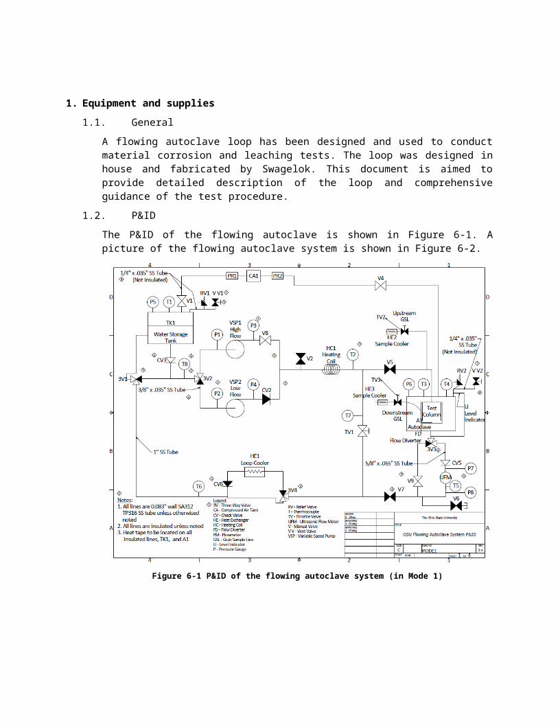
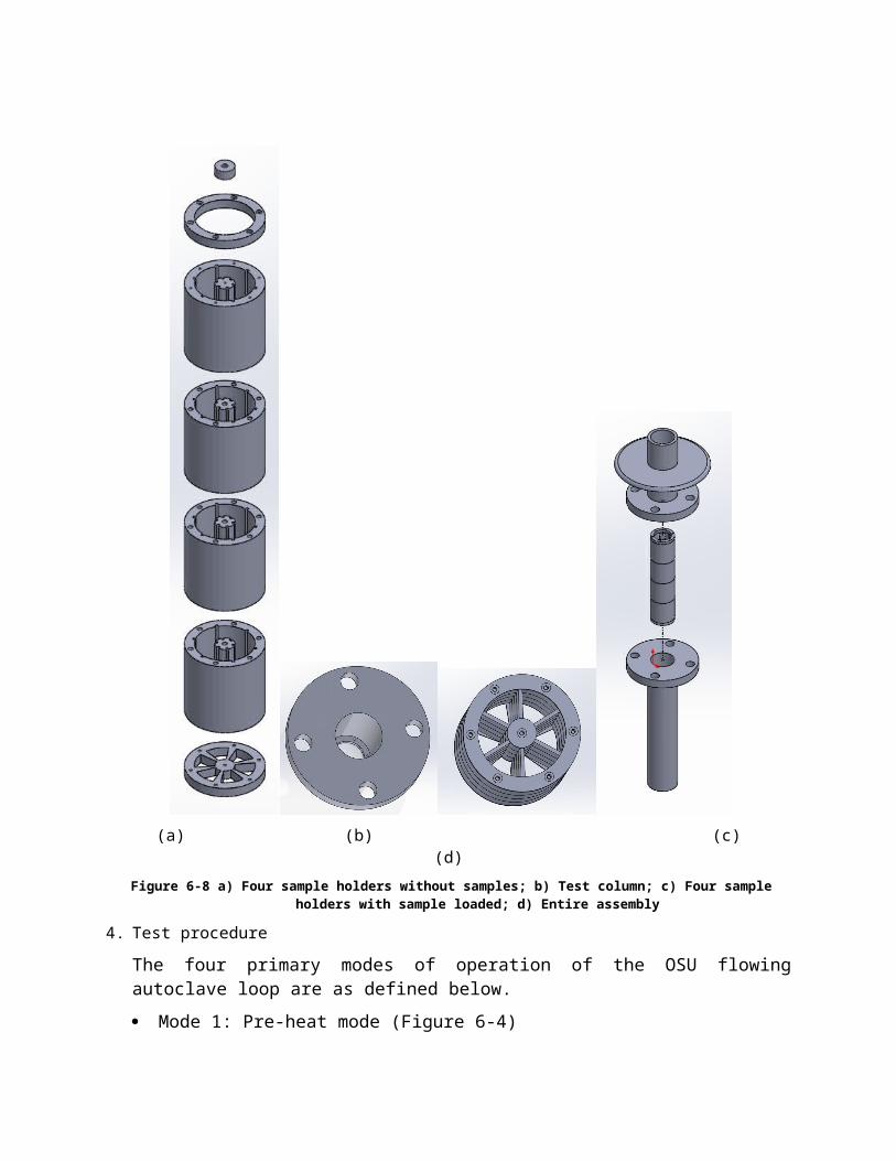

2 Pump operation
- Switch on the power supply shown in Figure
- Press ldquoRUNrdquo and ldquoSTOPrdquo on the VFD to start and shut the pump
- Press up and down arrow to increase and decrease the pump frequency
Small flow pump operation instructions
1 Operation conditions
The large flow pump (VSP2) has restrict requirements on the conditions up which it is running All these requirements should be rigorously to prevent potential damage to the pump
Temperature 300 F (149 C)
Material compatibility see manuals for detailed information
2 Pump operation
To adjust the flow rate rotate the black knob on the left hand side in the picture shown below
The dial shows the percentage of the max flow rate
U3000 ultrasonic flow meter operation instructions1 Operation conditions
The maximum allowable temperature 200 C
Flow rate range
2 Operation procedure
Rail and transducer installation
For detail see the manual online
httpwwwheattracingcoukuploadMicronics-Ultrasonic-Clamp-On-Flow-Meter---Portable-and-Permanent-Flow-Meters---Ultraflo-U3000-and-U4000---User-Manualpdf
REFERENCE
[1] Flowing Autoclave 116rdquo Sample Holder Prototype Design Rev 01 Document No CET-OSU-SAMPLE-HOLDER
[2] SYL-2362A2 PID Temperature Controller Instruction Manual Version 24 httpauberinscomimagesManualSYL-236220instruction2016pdf Auber Instruments
[3] OSU Flowing Autoclave System PampID Rev 04
[4] Design Inputs for Flowing Autoclave System MEMO-9050-MEM-2014-1 Rev 1
- Large flow pump operation instructions
- Small flow pump operation instructions
- U3000 ultrasonic flow meter operation instructions
-