nmc exam brush-up · nmc exam brush-up november 2009. ... microdefects (point defects, line defects...
TRANSCRIPT
NMC EXAM BRUSH-UPNOVEMBER 2009
OVERVIEW
1. Crystal Structures
2. Solidification and Crystal Defects
in Solids
3. Heat Treatments
4. Electrical Properties of Materials
5. Magnetic Properties of Materials
CRYSTAL STRUCTURES
Chapter 3
CRYSTAL STRUCTURES
What do I need to know?
Main Metallic Crystal Structures
FCC, BCC, HCP, BCT
Polymorphism
Unit Lattices and Bravais Lattices
Density Tool Box
Close-packed Crystal Structures
MAIN METALLIC CRYSTAL STRUCTURES
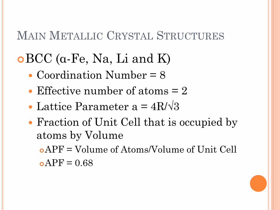
BCC (α-Fe, Na, Li and K)
Coordination Number = 8
Effective number of atoms = 2
Lattice Parameter a = 4R/√3
Fraction of Unit Cell that is occupied by
atoms by Volume
APF = Volume of Atoms/Volume of Unit Cell
APF = 0.68
MAIN METALLIC CRYSTAL STRUCTURES
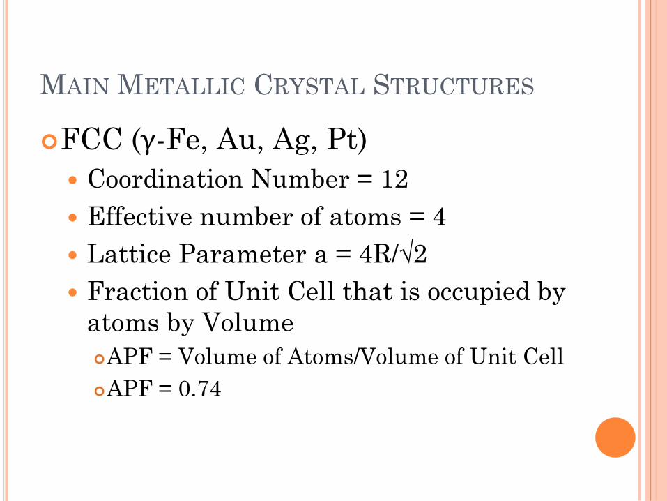
FCC (γ-Fe, Au, Ag, Pt)
Coordination Number = 12
Effective number of atoms = 4
Lattice Parameter a = 4R/√2
Fraction of Unit Cell that is occupied by
atoms by Volume
APF = Volume of Atoms/Volume of Unit Cell
APF = 0.74
MAIN METALLIC CRYSTAL STRUCTURES
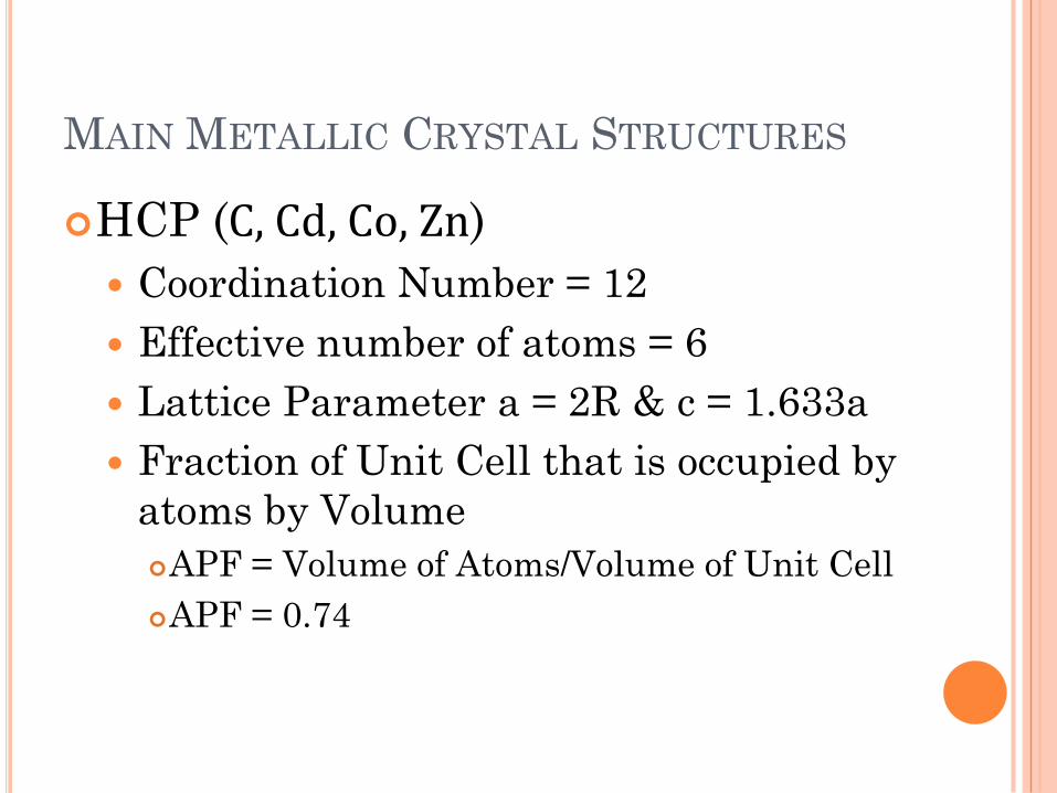
HCP (C, Cd, Co, Zn)
Coordination Number = 12
Effective number of atoms = 6
Lattice Parameter a = 2R & c = 1.633a
Fraction of Unit Cell that is occupied by
atoms by Volume
APF = Volume of Atoms/Volume of Unit Cell
APF = 0.74
MAIN METALLIC CRYSTAL STRUCTURES
Examples1. Calculate the radius of an iridium atom. Ir has
an FCC crystal structure and a density of
22.4g/cm3 and an atomic weight of 192.2g/mol
(R = 0.136nm)
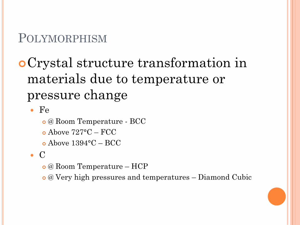
POLYMORPHISM
Crystal structure transformation in
materials due to temperature or
pressure change Fe
@ Room Temperature - BCC
Above 727°C – FCC
Above 1394°C – BCC
C
@ Room Temperature – HCP
@ Very high pressures and temperatures – Diamond Cubic
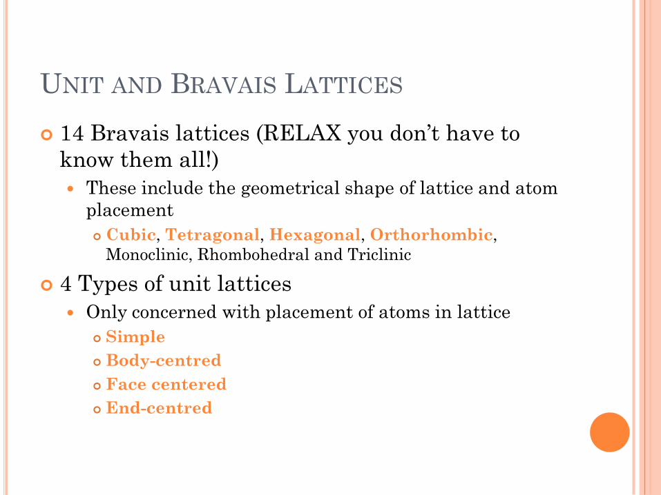
UNIT AND BRAVAIS LATTICES
14 Bravais lattices (RELAX you don’t have to
know them all!)
These include the geometrical shape of lattice and atom
placement
Cubic, Tetragonal, Hexagonal, Orthorhombic,
Monoclinic, Rhombohedral and Triclinic
4 Types of unit lattices
Only concerned with placement of atoms in lattice
Simple
Body-centred
Face centered
End-centred
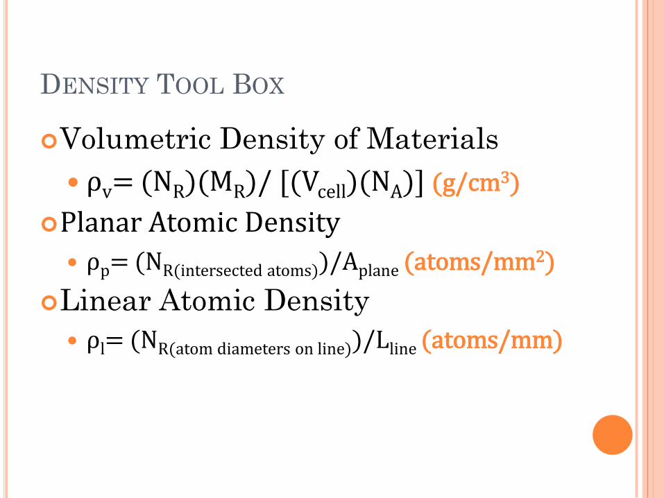
DENSITY TOOL BOX
Volumetric Density of Materials
ρv= (NR)(MR)/ [(Vcell)(NA)] (g/cm3)
Planar Atomic Density
ρp= (NR(intersected atoms))/Aplane (atoms/mm2)
Linear Atomic Density
ρl= (NR(atom diameters on line))/Lline (atoms/mm)
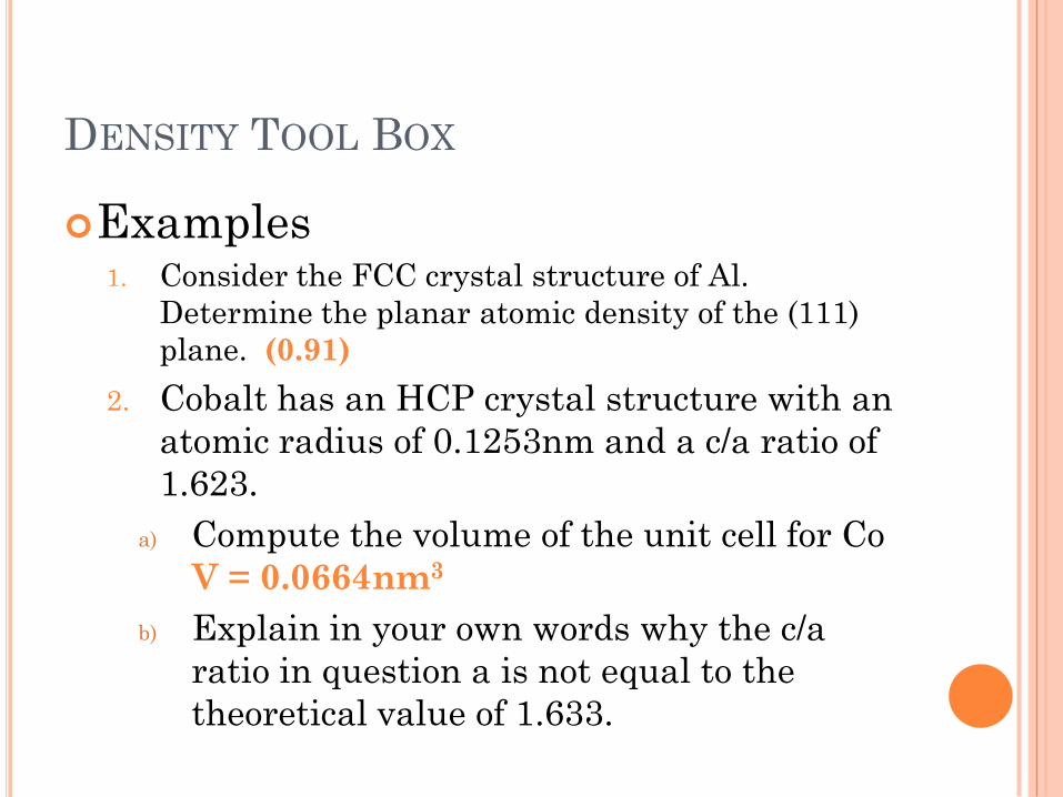
DENSITY TOOL BOX
Examples1. Consider the FCC crystal structure of Al.
Determine the planar atomic density of the (111)
plane. (0.91)
2. Cobalt has an HCP crystal structure with an
atomic radius of 0.1253nm and a c/a ratio of
1.623.
a) Compute the volume of the unit cell for Co
V = 0.0664nm3
b) Explain in your own words why the c/a
ratio in question a is not equal to the
theoretical value of 1.633.
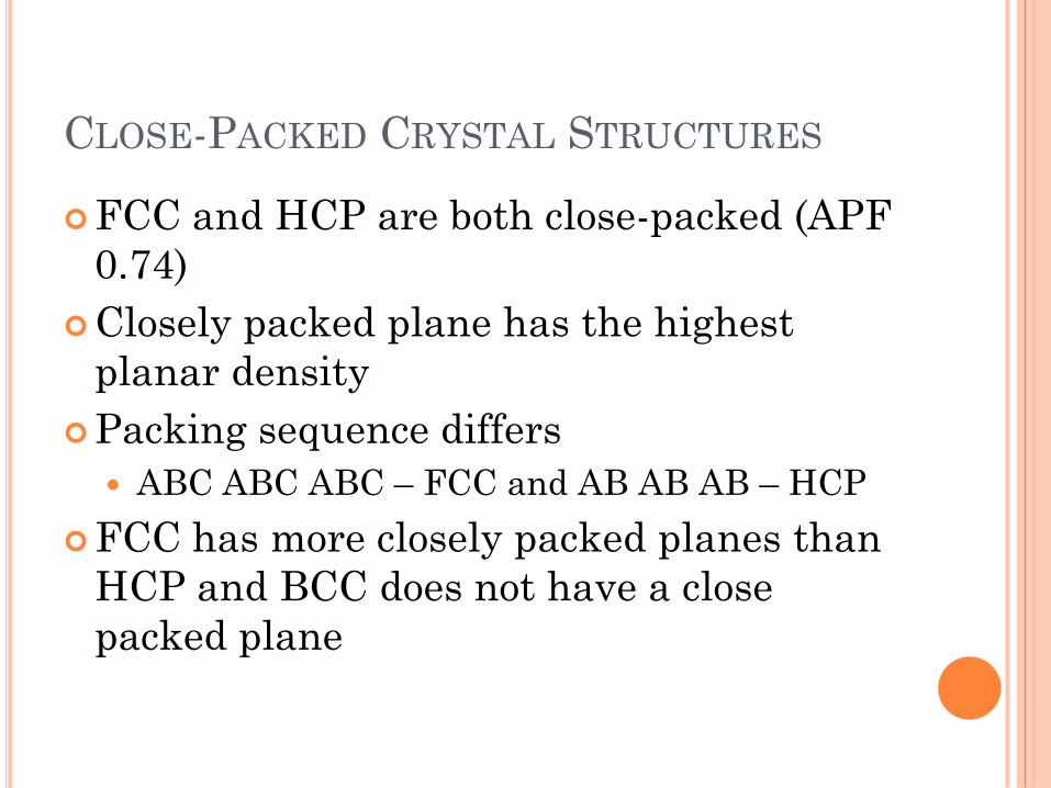
CLOSE-PACKED CRYSTAL STRUCTURES
FCC and HCP are both close-packed (APF
0.74)
Closely packed plane has the highest
planar density
Packing sequence differs
ABC ABC ABC – FCC and AB AB AB – HCP
FCC has more closely packed planes than
HCP and BCC does not have a close
packed plane
SUMMARY: TIPS AND FURTHER EXAMPLES
Exam questions will most likely be more focused
on calculations than the theory of this chapter
Familiarise yourself with the sketches of FCC,
BCC, HCP and BCT
If you can sketch it, CN, Atoms per unit cell
and APF can be UNDERSTOOD
Principle for Ionic crystals are similar just note
that the cation and anion valences HAVE TO
BALANCE
Prove to yourself that the c/a ratio = 1.633 for an
ideal HCP crystal
ALWAYS DRAW A PICTURE!!!
IMPERFECTIONS IN SOLIDS
Chapter 4
CRYSTAL STRUCTURES
What do I need to know? Process of Solidification
Polycrystalline Metals (Sketch ingot
solidification mechanism)
Single Crystals (Chozkralski process)
Defects in Solids
Influencing factors
Types of Defects
Calculating Grain Size
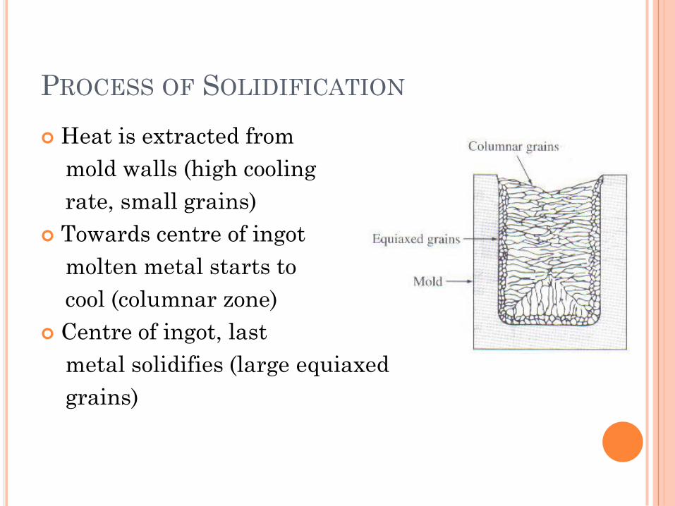
PROCESS OF SOLIDIFICATION
Heat is extracted from
mold walls (high cooling
rate, small grains)
Towards centre of ingot
molten metal starts to
cool (columnar zone)
Centre of ingot, last
metal solidifies (large equiaxed
grains)
DEFECTS IN SOLIDS
Influencing Factors
Mechanical Properties
Ductility
Electrical Properties
Conductivity
Heat conductivity ability
Diffusion of atoms
Corrosion resistance
Types of Defects
Microdefects (point defects, line defects and surface defects)
Macrodefects (Cracks, pores, inclusions and blow holes)
DEFECTS IN SOLIDS
Microdefects – Point Defects
Vacancies
Nc = Ne(-Qv/kT)
Self-interstitial Defects
Impurities
Most materials are used in alloy form
Simplest alloy is that of solid solution
Substitutional (Alloying atoms replaces that of paremt
atoms)
Interstitial (Alloying atoms positions between parent
atoms)
Excess alloying elements above saturation limit –
two-phase solid
Solid solution also depends on Hume-Rothery criteria
DEFECTS IN SOLIDS
Microdefects – Point Defects
Hume-Rothery Criteria
Rparent and Ralloy difference < 15%
Parent and alloy crystal structure must be similar
Electron negativity of 2 elements must be about equal
2 Elements must have the same number of valence
electrons
Schottky Defects (Ceramics)
Missing cation AND anion
Frenkel Defects (Ceramics)
Cation vacancy
DEFECTS IN SOLIDS
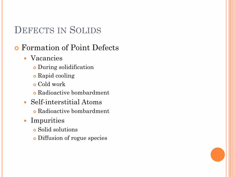
Formation of Point Defects
Vacancies
During solidification
Rapid cooling
Cold work
Radioactive bombardment
Self-interstitial Atoms
Radioactive bombardment
Impurities
Solid solutions
Diffusion of rogue species
DEFECTS IN SOLIDS
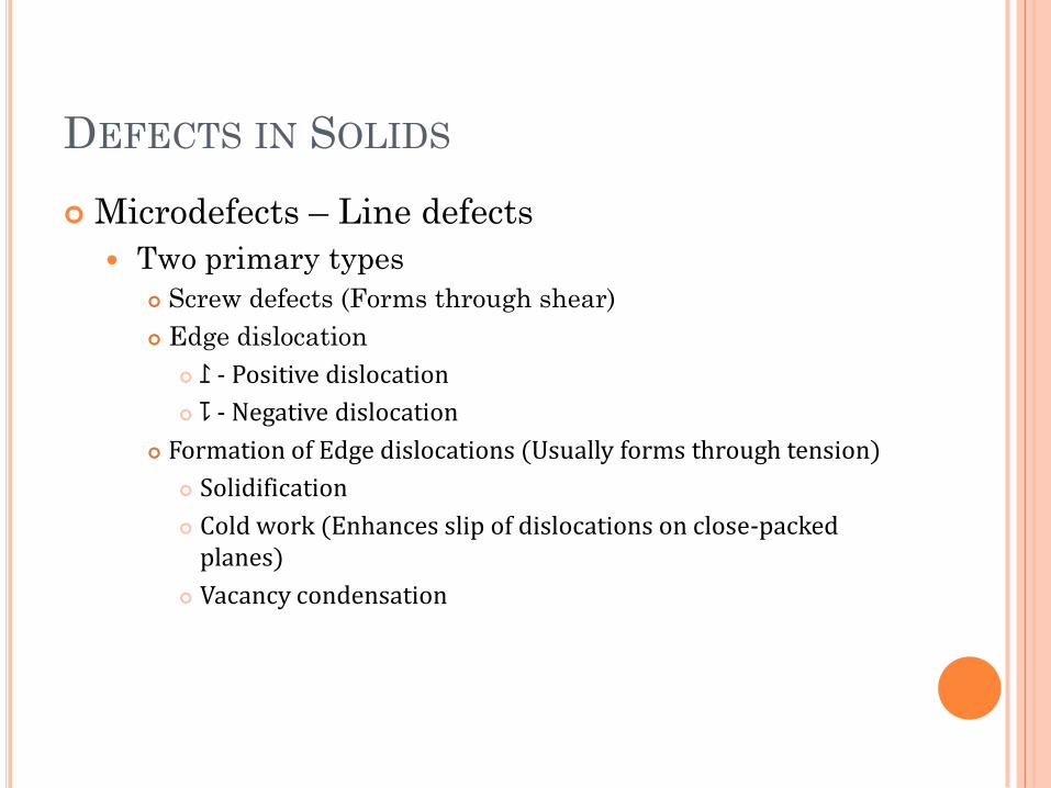
Microdefects – Line defects
Two primary types
Screw defects (Forms through shear)
Edge dislocation
⥜ - Positive dislocation
⥝ - Negative dislocation
Formation of Edge dislocations (Usually forms through tension)
Solidification
Cold work (Enhances slip of dislocations on close-packed planes)
Vacancy condensation
DEFECTS IN SOLIDS
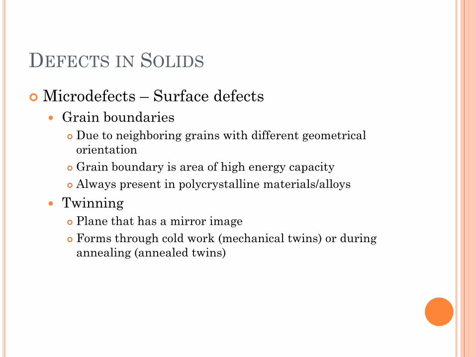
Microdefects – Surface defects
Grain boundaries
Due to neighboring grains with different geometrical
orientation
Grain boundary is area of high energy capacity
Always present in polycrystalline materials/alloys
Twinning
Plane that has a mirror image
Forms through cold work (mechanical twins) or during
annealing (annealed twins)
DEFECTS IN SOLIDS
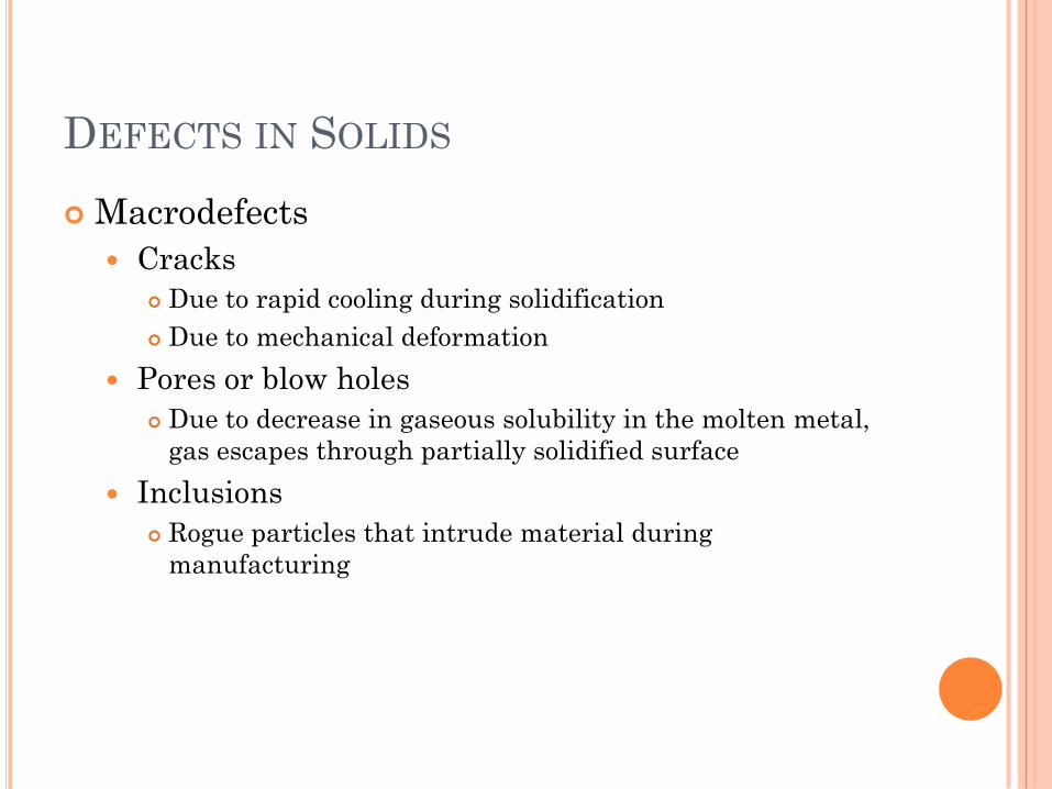
Macrodefects
Cracks
Due to rapid cooling during solidification
Due to mechanical deformation
Pores or blow holes
Due to decrease in gaseous solubility in the molten metal,
gas escapes through partially solidified surface
Inclusions
Rogue particles that intrude material during
manufacturing
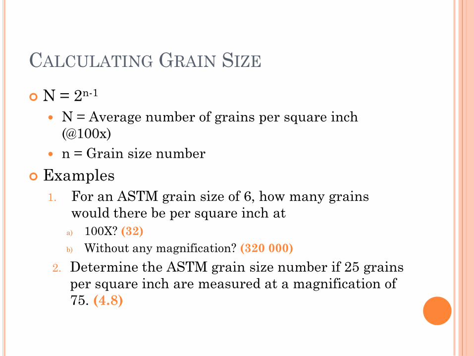
CALCULATING GRAIN SIZE
N = 2n-1
N = Average number of grains per square inch
(@100x)
n = Grain size number
Examples
1. For an ASTM grain size of 6, how many grains
would there be per square inch at
a) 100X? (32)
b) Without any magnification? (320 000)
2. Determine the ASTM grain size number if 25 grains
per square inch are measured at a magnification of
75. (4.8)
ANOTHER EXAMPLE
3. Calculate the fraction of atom sites that are vacant
for Pb at its melting temperature of 327°C. Assume
an energy for vacancy formation of 0.55eV/atoms.
(2.41x10⁻⁵)
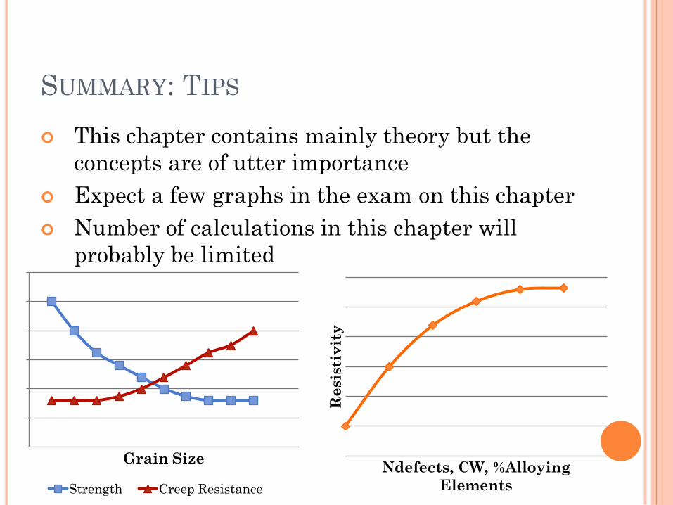
SUMMARY: TIPS
This chapter contains mainly theory but the
concepts are of utter importance
Expect a few graphs in the exam on this chapter
Number of calculations in this chapter will
probably be limited
0
2
4
6
8
10
12
Grain Size
Strength Creep Resistance
Resis
tiv
ity
Ndefects, CW, %Alloying
Elements

HEAT TREATMENT
Chapter 9
HEAT TREATMENT
What do I need to know? Fe-C phase system
Interpretation of binary phase diagram
Phases present at specific temperature and composition
Lever-rule for calculating percentage of different phases at
temperatures and compositions
Phase transformations (peritectic, eutectic, eutectoid and
peritectoid reactions)
Equilibrium phases and reactions
Non-equilibruim phases
Heat treatments and microstructures
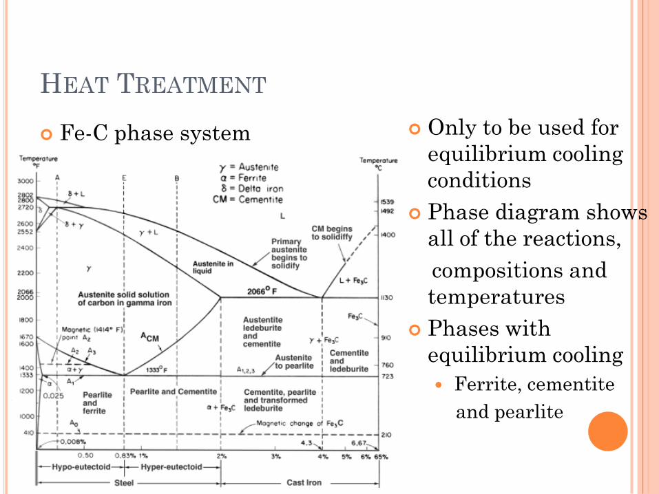
HEAT TREATMENT
Fe-C phase system Only to be used for
equilibrium cooling
conditions
Phase diagram shows
all of the reactions,
compositions and
temperatures
Phases with
equilibrium cooling
Ferrite, cementite
and pearlite
HEAT TREATMENT
Fe-C phase system Examples
1. By using the Fe-C phase diagram, answer the
following questions applicable to a 0.5%C
hypoeutectoid steel that is cooled slowly from
950°C to just below 727°C.
a) Calculate the amount of proeutectoid ferrite in the
steel (38.71%)
b) Calculate the amounts of eutectoid ferrite and
eutectoid cementite in the steel (54.17% and 7.1%)
HEAT TREATMENT
Fe-C phase system Examples
2. Determine the chemical compositions of steels
containing the following microstructural
components after cooling
a) 92% Ferrite and 8% Cementite (0.559%C)
b) 48.2% Proeutectoid ferrite (0.426% C)
c) 4.7% Proeutectoid cementite (1.0773% C)
d) 10.45% Eutectoid cementite (Hypereutectoid
composition) (1.388% C)
HEAT TREATMENT
Non-equilibrium Phases Transformations
Increase in cooling rate – non-equilibrium phases Bainite – T from 250 – 550°C
Fine dissemination of cementite in ferrite matrix
Good toughness, strength and hardness properties
Martensite – Rapid cooling (quenching in water or brine)
C atoms don’t have time to diffuse out of FCC structure, are trapped in BCT cell
Due to high amount of distortion associated with phase transformation, hardness and strength of martensite is very high
Temper treatment is often need to restore ductility of martensite
Tempering occurs below 650°C and allows C to precipitate out – also known as spherodising – internal stresses are relieved and ductility is improved
HEAT TREATMENT
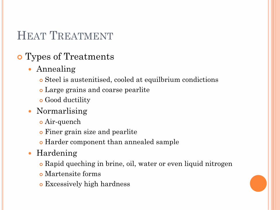
Types of Treatments
Annealing
Steel is austenitised, cooled at equilbrium condictions
Large grains and coarse pearlite
Good ductility
Normarlising
Air-quench
Finer grain size and pearlite
Harder component than annealed sample
Hardening
Rapid queching in brine, oil, water or even liquid nitrogen
Martensite forms
Excessively high hardness
HEAT TREATMENT
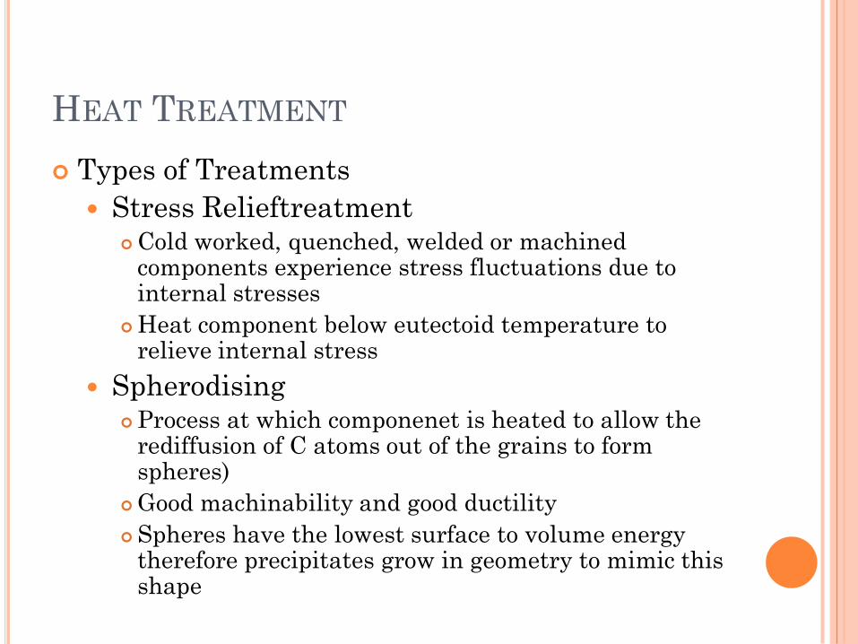
Types of Treatments
Stress RelieftreatmentCold worked, quenched, welded or machined
components experience stress fluctuations due to internal stresses
Heat component below eutectoid temperature to relieve internal stress
SpherodisingProcess at which componenet is heated to allow the
rediffusion of C atoms out of the grains to form spheres)
Good machinability and good ductility
Spheres have the lowest surface to volume energy therefore precipitates grow in geometry to mimic this shape
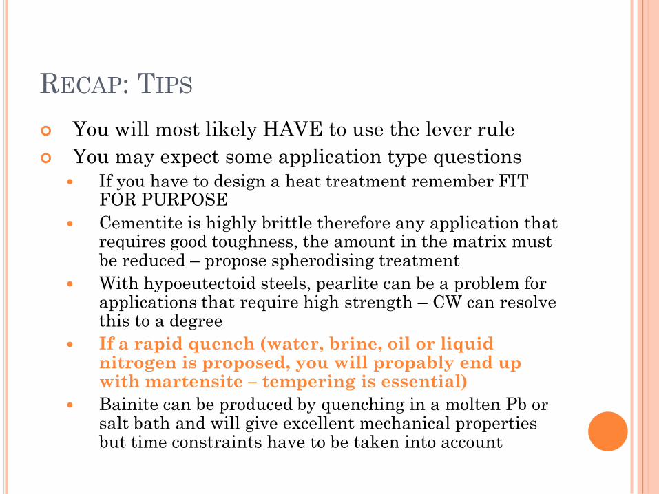
RECAP: TIPS
You will most likely HAVE to use the lever rule
You may expect some application type questions
If you have to design a heat treatment remember FIT FOR PURPOSE
Cementite is highly brittle therefore any application that requires good toughness, the amount in the matrix must be reduced – propose spherodising treatment
With hypoeutectoid steels, pearlite can be a problem for applications that require high strength – CW can resolve this to a degree
If a rapid quench (water, brine, oil or liquid nitrogen is proposed, you will propably end up with martensite – tempering is essential)
Bainite can be produced by quenching in a molten Pb or salt bath and will give excellent mechanical properties but time constraints have to be taken into account
ELECTRICAL PROPERTIES OF
MATERIALS
Chapter 14
ELECTRICAL PROPERTIES OF MATERIALS
What do I need to know? Relationship between resistivity and conductivity
3 Groups of electrical conductivity
Factors that influence resistivity and conductivity
Energy gap model for metals and isolators
Intrinsic semi-conductors
Extrinsic semi-conductors
Dielectric character
ELECTRICAL PROPERTIES OF MATERIALS
Resistivity and Conductivity
Inversely proportional to each other
Resistance of material is dependent on the type of
material, length and cross-sectional area of
component
Ohm’s law can be used to determine Resistance and
the micro-law can be used to determine conductivity
or resistivity
3 Types of Conductors
Conductor (e.g. Metals with high conductivity)
Semi-conductors (e.g. Si with moderate conductivity)
Isolators (e.g. Ceramics with poor conductivity)
ELECTRICAL PROPERTIES OF MATERIALS
Factors that influence resisitivity
Temperature
Linear relationship between resistivity and temperature
Purity of metal
Alloying elements increase resistivity as electrons have less
mobility in the crystal structure
Crystal Defects
An increase in the crystal defects will facilitate an increase
in the resistivity as they will form barriers against the
movement of electrons
Resistivity can be reduced by heat treatments (HX)
ELECTRICAL PROPERTIES OF MATERIALS
Energy gap model
Metals
Small amount of energy needed to fill energy gap with
metals
Therefore most metals have good conductivity
Isolators
Energy gap is separated from a filled band and an empty
band
Electrons need a lot more energy to cross energy gap
therefore conductivity is lower
ELECTRICAL PROPERTIES OF MATERIALS
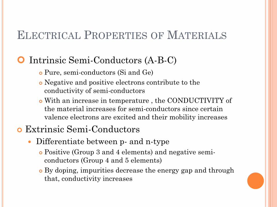
Intrinsic Semi-Conductors (A-B-C)
Pure, semi-conductors (Si and Ge)
Negative and positive electrons contribute to the
conductivity of semi-conductors
With an increase in temperature , the CONDUCTIVITY of
the material increases for semi-conductors since certain
valence electrons are excited and their mobility increases
Extrinsic Semi-Conductors
Differentiate between p- and n-type
Positive (Group 3 and 4 elements) and negative semi-
conductors (Group 4 and 5 elements)
By doping, impurities decrease the energy gap and through
that, conductivity increases
ELECTRICAL PROPERTIES OF MATERIALS
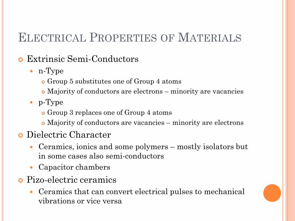
Extrinsic Semi-Conductors
n-Type
Group 5 substitutes one of Group 4 atoms
Majority of conductors are electrons – minority are vacancies
p-Type
Group 3 replaces one of Group 4 atoms
Majority of conductors are vacancies – minority are electrons
Dielectric Character
Ceramics, ionics and some polymers – mostly isolators but
in some cases also semi-conductors
Capacitor chambers
Pizo-electric ceramics
Ceramics that can convert electrical pulses to mechanical
vibrations or vice versa
RECAP
This chapter consists of 90% theory
The few electrical formulas – Ohm’s law etc have been
covered extensively at high school level but if you have any
questions please don’t hesitate to ask
Do some exercises on extrinsic semi-conductors just to
familiarise yourself with the equations
It’s literally plug-and-play equations with very little
complicated calculations
Once again it’s important to UNDERSTAND the factors
that will influence conductivity and resistivity
You can expect maybe two graphs on this chapter, some
monkey puzzle questions and maybe 1 calculation
(Probably from the extrinsic semi-conductors section)
MAGNETIC PROPERTIES OF
MATERIALS
Chapter 20
MAGNETIC PROPERTIES OF MATERIALS
What do I need to know? Basic Principles (Theory)
Magnetic field strength and magnetic density
Relative permeabilities
Types of magnetism
Diamagnetic, paramagnetic, ferromagnetic, antiferromagne
tic and ferrimagnetic
Influence of Temperature on Ferromagnetics
Hysteresis
Magnetisation and demagnetisation and hysteris loops
Differentitate between hard and soft magnetics
MAGNETIC PROPERTIES OF MATERIALS
Types of Magnetism Types of magnetism
Diamagnetic - μr < 1
Paramagnetic – particles move toward external magnetic
field but loses their magnetism when field is removed
Ferromagnetic – Magnetisation can be permanent due to
the half-filled orbital of elements. It is essential that
electrons in the 3d orbital are unpaired
Antiferromagnetic – Elements have a magnetic moment but
the a/d ratio is does not range between 1.4 and 2.7 – no
magnetism
Ferrimagnetism – Traces magnetic moments – usually ionic
bonds- spine of electrons are anti-parrallel but not magnetic
MAGNETIC PROPERTIES OF MATERIALS
Influence of Temperature on
Ferromagnetics At the Curie temperature, the 3d-electrons’
orientations changes and the parallel spin of the
electrons decrease
At this temperature the ferromagnetic nature of the
material is destroyed
MAGNETIC PROPERTIES OF MATERIALS
Hysteresis Domains on atomic level can be altered via a solenoid
– causes parallel movement of 3d-electrons
Magnetisation occurs with ferromagnetic and
ferrimagnetic materials due
Domains (which have the correct orientation) start to grow
at the expense of incorrect orientated domains
Incorrect orientated domains can be rotated if the applied
field strength is strong enough
Demagnetisation will occur if the material is heated
above its Curie temperature, by applying an opposite
directed field strength or increasing the dislocation
density of the material
MAGNETIC PROPERTIES OF MATERIALS
Hysteresis
So-called hysteresis loop shows the
life-cycle of a ferromagnetic
material
The larger the area of the
curve, the easier magnetisation is
possible
MAGNETIC PROPERTIES OF MATERIALS
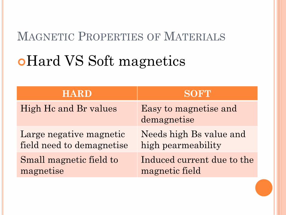
Hard VS Soft magnetics
HARD SOFT
High Hc and Br values Easy to magnetise and
demagnetise
Large negative magnetic
field need to demagnetise
Needs high Bs value and
high pearmeability
Small magnetic field to
magnetise
Induced current due to the
magnetic field
RECAP
The theory of this chapter is the
most important since there are very
few types of calculations that can be
asked of you
Types of magnets is quite important
also the mechanism that allows
ferromagnetism
B-H curve is very easy to
understand – just follow your notes