n/lsa - nasa · pdf filen/lsa https: //ntrs.nasa.gov ... dynamic analysis program pressure...
TRANSCRIPT
NASA Contractor Re 0!%:!--_
k_ +-
Design of Fuselage Shapes
for Natural Laminar Flow
S. S. Dodbele, C. P. van Dam,
and P. M. H. W. Vijgen
CONTRACT NAS1-17926
MARCH 1986
N/LSA
https://ntrs.nasa.gov/search.jsp?R=19860014381 2018-04-25T08:43:33+00:00Z
_- --_'-_.:_.=.
o
_2: :-:::--.... c---
7--:Z==_--Z 2. -
. _C__=_ b=_-

NASA Contractor Report 3970
Design of Fuselage Shapes
for Natural Laminar Flow
S. S. Dodbele and C. P. van Dam
Vigyan Research Associates, Inc.
Hampton, Virginia
P. M. H. W. Vijgen
Univeristy of Kansas
Lawrence, Kansas
Prepared for
Langley Research Centerunder Contract NAS1-17926
National Aeronautics
and Space Administration
Scientific and TechnicalIntormation Branch
1986


Table of Contents
Page
Abstract ............................... v
Nomenclature ............................. vi
Introduction ............................. I
Computational Design Procedure .................... 4
Aerodynamic Analysis ......................... 6
Results from the Design Procedure .................. II
Summary ............................... 12
References .............................. 14
Appendix .............. 16
Table ................................ 19
Figures 20• • . • • • • • • • • • • • • • • ° • • ° • • • ° • • • • • •
iii


Abstract
Recent technological advances in airplane construction techniques and
materials employing bonded and milled aluminum skins and composite materials
allow for the production of aerodynamic surfaces without significant waviness
and roughness, permitting long runs of natural laminar flow (NLF). These
advances lead to excellent opportunities for reducing the drag of aircraft by
increasing the extent of NLF. The present research effort seeks to refine and
validate computational design tools for use in the design of axisymmetric and
nonaxisymmetric natural-laminar-flow bodies. The principal tasks of the
investigation involve fuselage body shaping using a computational design proce-
dure.
Under Phase I SBIR funding for this research, analytical methods were refined
and exploratory calculations were conducted to predict laminar boundary-layer
behavior on selected body shapes. Using a low-order surface-singularity aero-
dynamic analysis program pressure distribution, boundary-layer development,
transition location and drag coefficient have been obtained for a number of
body shapes including a representative business-aircraft fuselage. Extensive
runs of laminar flow were predicted in regions of favorable pressure gradient
on smooth body surfaces. A computational design procedure was developed to
obtain a body shape with minimum drag coefficient having large extent of NLF.
Some preliminary results from the design efforts have been obtained and further
work is underway.
The proposed study has widespread commercial applications. A significant
reduction in the drag produced by any airplane can be obtained when extensive
runs of natural laminar flow are achieved on its fuselage resulting in improved
airplane performance and efficiency.
V

Nomenclature
CD
Cp
D
fr
H
k 1
L
M
NLF
n
Ri
Rn
RL
Rs
Rx
Rv
R_
r i
r n
r
Si
S
s i
Drag coefficient
Pressure coefficient
Maximum diameter
Fineness ratio, length/maximum diameter
Boundary-layer shape factor, _*/e
Nondimensional curvature at x m
Body length
Mach number
Natural Laminar Flow
Logarithmic exponent of T-S wave growth ratio
Profile radius at x i
Radius of curvature at the nose
Reynolds number based on free-stream conditions and bodylength
Reynolds number based on local conditions and surfacelength
Reynolds number based on local conditions and axial length
Body volume Reynolds number based on free-stream conditions
and VI/3
Reynolds number based on local conditions and boundary-layermomentum thickness
Nondimensional profile radius of x i, 2frRi/L
Nondimensional radius of curvature at the nose, 4XmfrRn/L
Nondimensional profile radius at x
Profile slope at x i
Surface length, starting at the nose
Nondimensional profile slope at x i,-2fr(Xi-X m) Si
(L-r i )
vi

o0
V
V
X
X.1
Xm
xm
X.1
Xsep
X
Z(x)
c_
0
ch
Free-stream velocity
Local velocity
Body volume
Axial coordinate, starting at the nose
Axial location of inflection point
Axial location of maximum diameter
Nondimensional axial location of maximum diameter, Xm/L
Nondimensional axial location of inflection point, Xi/L
Nondimensional axial length coordinate of boundary-layerseparation
Nondimensional axial location, X/L
Nondimensional thickness distribution
Angle of attack (degrees)
Boundary-layer displacement thickness
Boundary-layer momentum thickness
Half trailing-edge angle at the tail (see fig. 15) in degrees
vii


1. Introduction
In recent years, airplane construction material and fabrication methods
have improved greatly, resulting in the production of airframe surfaces which
accurately match the design shape. Recent flight tests (refs. I and 2) have
demonstrated that extensive runs of laminar boundary layer flow can be obtained
over regions of favorable pressure gradient on smooth airplane surfaces and
provide a significant reduction in profile drag. A major portion of the past
research effort for achieving and maintaining natural laminar flow (NLF) has
been focused on aircraft wings. Fuselage shaping to increase the extent of
NLF has received much less attention in the literature except for sailplane
bodies and hydrodynamic bodies.
Althaus (ref. 3) conducted experimental investigations in order to show
the possible reduction in drag of sailplane fuselages and study the flow inter-
action of the fuselage with a wing and the influence of various wing positions.
In reference 4 an analytical and experimental study on NLF nacelles demonstrates
the presence of significant regions of laminar flow on the surface of a turbo-
fan engine nacelle. Sub-scale wind-tunnel testing of the NLF nacelle indicated
a potential of 1.5-2.0 percent reduction in total airplane drag by maintaining
laminar boundary-layer flow over extensive regions of the external nacelle
surface. The pay-off in terms of airplane profile drag reduction can be much
larger when considering the application of low-drag NLF design to airplane
fuselages. The importance of fuselage skin-friction drag is clearly indicated
in figure I, in which a profile drag breakdown is shown for a typical transport
jet (ref. 5). The fuselage generates less than 50 percent of the profile drag
for the all-turbulent airplane. However, it is estimated that the contribution
of the fuselage to airplane profile drag increases to more than 70 percent of

the total profile drag if extensive regions of natural laminar flow are
achieved on the wing and tail surfaces. The present study will investigate
the design of fuselage shapes that result in extensive regions of NLF at
conditions corresponding to typical cruise Reynolds numbers encountered by
touring, business and transport airplanes.
Carmichael (ref. 6) did an experimental study on a body of fineness
ratio of 3.33 developed by revolving the coordinates of a NACA-66 laminar flow
airfoil about the longitudinal axis. This tailboomed body (called the Dolphin)
was tested over a Reynolds number range of 20 million to 30 million (based on
body length) and transition length Reynolds numbers of 14 million to 18 million
were obtained. Boundary-layer transition from laminar to turbulent flow
apparently occured beyond the point of maximum thickness. These results
indicate that a low fineness ratio and a proper shape can produce a strong
favorable pressure graident (and therefore a strong flow acceleration) on the
forebody of the configuration. As a result the boundary layer stays laminar
over an appreciable distance.
Dalton and Zedan (ref. 7) presented an inverse method to design low-drag
axisymmetric body shapes. A prescribed surface-velocity distribution is input
and the corresponding body shape is computed. The method is based on represent-
ing the body of revolution by a source distribution of variable intensity along
its axis. Dalton and Zedan applied the method to carry out a design study for
bodies at a volume Reynolds number Rv = 50 million. This Reynolds number is
representative for large torpedo and small airship applications and it
corresponds to a length Reynolds number RL of approximately 200 million
depending on body shape.
Forebody shapes of missiles designed specifically for long runs of NLF at
compressible free-stream velocities have been studied in reference 8. In

reference 8, results computed for three forebody shapes of different fineness
ratios (I.0, 1.5 and 2.0) indicate that laminar flow can be obtained for high
Reynolds numbers and high subsonic Mach numbers. The design condition for
these relatively blunt forebody shapes was a unit Reynolds number of 40 million
per foot and a Mach number of 0.75. However, the Reynolds number range which
is encountered by most airplanes is in the range of 1-3 million per foot.
Therefore, the results of reference 8 are not very useful for the design of
fuselage forebodies for subsonic airplanes.
Parsons and his coworkers (refs. 9 and 10) have given a procedure to
design axisymmetric bodies for minimum drag for hydrodynamic applications.
Drag reduction is accomplished solely through manipulation of the vehicle shape.
The optimization problem is formulated as a nongradient search in a finite
constrained parameter space. Two classes of bodies, described by five and
eight parameters, are considered. The requirement for nonseparating flow
represents an additional constraint on the optimization problem. The axisym-
metric bodies are represented by axial singularity distribution and the drag
coefficient is evaluated using Young's formula. The results show that signifi-
cant drag reduction is possible through shape manipulation. Pinebrook (refs.
II and 12) devised a technique, based on an evolution strategy, to minimize
the drag of an axisymmetric body with a given maximum body diameter and fineness
ratio. The body profile is described by continuous first order axial
singularity distribution defined at 21 points. The gradual body profile
changes are effected through a process derived from the evolution strategy. The
drag is calculated from the momentum deficit in the boundary layer at the
end of the body using Young's formula (ref. 13). The bodies designed by
Pinebrook had laminar flow only up to 3 percent of the body length from the nose

at which location the boundary layer was tripped.
According to von Karman(ref. 14) not every axisymmetric body can be
represented accurately by an axial source distribution. Also, recently Hess
(ref. 15) pointed out that the line sources cannot extend to the ends of the
body at finite strengths otherwise the velocities there will be infinite. These
problems with the axial singularities are eliminated if one uses panel methods
with which the body is represented by aerodynamic surface panels. Here, a
computational procedure was developed to obtain fuselage geometries for consider-
able extent of laminar flow and hence for low skin-friction drag.
Computational Design Procedure
The computational design procedure used to obtain "natural laminar flow
fuselage" geometries is described in the flow chart (see fig. 2). Initial
values of the design variables describing the body shape are input along with
the Reynolds number (based on length), the nondimensional length and the
fineness ratio. The axisymmetric body is described by seven parameters. The
expressions to obtain the body shape are given in the Appendix.
A number of constraints are imposed on the design parameters in order to
generate designs which are realistic and practical. The geometric constraints
are given below.
I. O<r n
2. O_k 1
3. 0 < Xm < xi < i
4. 0 <=ri_< I
5. O<s i
6. 5° __< =<80°
7. No inflection on forebody, midbody and afterbody except at x i.

These conditions are taken care of by choosing proper upper and lower bounds
for the design variables.
The other constraint is that the separation takes place very near the
trailing edge. The following constraint is imposed in the optimization proce-
dure:
0.95 _ Xsep
The objective function is taken to be body profile drag coefficient which is
obtained by Young's formula (ref. 13). This objective function is to be
minimized subjected to the constraints which are given above. The optimizer
computes the gradients of the objective function and then, using either a
conjugate direction method or a method of feasible direction, determines a
linear search direction, along which a new constrained variable is constructed.
An improved or minimumfeasible objective functional value is evaluated
and a series of proposed updated design variables are calculated. The objective
function and the constrained function are evaluated using the updated design
variables, interpolating over the range of feasible proposed design variables
resulting in a minimumvalue of the objective function. The results are tested
against a convergence criteria. The procedure will stop if the convergence
criteria is satisfied giving a body shape with minimumdrag or maximumtransi-
tion length satisfying the separation constraint. If the convergence criteria
is not satisfied the design parameters go through the analyzer again resulting
in a new set of design variables and the procedure is repeated until a final
shape is obtained. The method involves a constrained minimization procedure
(ref. 25) coupled with an aerodynamic analysis program based on a low-order
surface singularity method named"VSAERO"(ref. 16). Pressure distribution and
velocity distribution can be computedby the aerodynamic analysis program which
uses surface singularity panels to represent the body. The program also calcu-

lates the effect of the viscous boundary layer adjacent to the body. Integral
methods are used to predict the boundary-layer development. The laminar part
of the boundary layer is calculated by Thwaite's methodwith Curle's modifica-
tion. Boundary-layer transition is predicted by Granville's procedure. Nash
and Hick's method is used for the turbulent boundary-layer calculations.
Laminar separation/turbulent reattachment calculations are done empirically
using Gaster's measurements.
Aerodynamic Analysis
To validate the surface singularity method, inviscid pressure distributions
have been obtained for the following configurations:
(a) a sailplane body,
(b) an axisymmetric body with an ogival nose, a cylindrical
center body and a flared afterbody,
(c) an ellipsoid of revolution,
(d) a body of revolution with a long favorable pressure
gradient,
(e) a low-drag body of revolution considered by Parsons
et al. (ref. 10)
(f) a representative business aircraft fuselage, and
(g) a body of revolution whose maximum diameter and length
correspond to those of the configuration (f).
In reference 3, Althaus presents wind-tunnel measurements on bodies and
wing-body combinations obtained at the University of Stuttgart. The measurements
include lift and drag characteristics, surface velocity distributions, and
boundary-layer transition locations. Each of the bodies of revolution had a fineness
ratio of i0 and a length of 6.56 ft (2.0 m) and the measurements were obtained at
6

a Reynolds number (based on body length) RL = 7.1 million. Althaus' body
shape 2 wasmodeled by surface singularity panels to obtain velocity distribu-
tions. In figure 3, the theoretical velocity distributions are comparedwith
surface velocity measurements. In the figure, the body shape is also shown
for this fuselage model. In the pressure recovery region theoretical results
do not agree very well with the wind-tunnel data. Also, at X/L = 0.12 a kink
appears in the calculated velocity distribution. This disturbance is produced
whenthe body coordinates as given by Althaus in reference 3 are used to model
the body shape. Consequently, the prediction of the boundary-layer transition
location does not agree very well with the experimental result. In the tunnel,
transition was measuredat X/L = 0.36 at RL = 7.1 million. The Granville
criterion predicted transition location at X/L = 0.29 which is
slightly forward comparedto the experimental result. This can be expected
becauseof the velocity discrepancies in the pressure-recovery region. These
discrepancies appear to be caused by wind-tunnel blockage effects, which
produce higher surface velocities near the location of maximumbody diameter.
Very good agreement betweenmeasuredand calculated surface pressure
coefficients was obtained for a body of revolution (configuration b) tested by
Fox in the NASALangley high-speed 7- by lO-foot wind tunnel (ref. 17). In
figure 4, the results are shownfor Fox's configuration 5, an axisymmetric body
composedof an ogival nose, a cylindrical centerbody and a flared afterbody.
Surface pressure data are plotted as function of the orifice location for the
orifices on the longitudinal meridian. By using the surface singularity
method, the pressure coefficients are obtained and they are also presented in
figure 4. The method allows modeling of the wake which originates from the
edge of the blunt base. However, for simplicity when the blunt base and the
sting were replaced with a lO-degree cone (the flared afterbody has an identical
slope of 10 degrees) the comparison of theoretical results with experimental
data showed very good agreement.
Measurements of pressure and boundary-layer transition were made on the
ellipsoid of revolution (configuration c) in wind tunnels and boundary-layer
transition was also measured in flight (ref. 18). Figure 5 presents the surface
pressure distribution and transition location for the ellipsoid of revolution of
fineness ratio 9. The viscous calculations were done at RL = 13.98 million.
As shown in the figure, although the pressure distributions compare well, the
computed transition location does not agree very well with the experimental data.
The transition length Reynolds number was 5.08 million. Granville's boundary-
layer transition criterion, which is used in the present computation, predicts
transition further downstream than was measured in the experiment (ref.
18). The same behavior occured when the Reynolds number was increased to 22.03
million. Kaups (ref. 19) also computed transition location for this ellipsoid
by using Granville's criterion and also arrived at the fact that at these two
Reynolds numbers, transition is predicted at points further downstream than at
the locations observed in the experiments (in flight and wind tunnel). Kaups
concluded that none of the transition prediction methods (including the e9-method
of Smith and Gamberoni) gave consistent satisfactory answers for the ellipsoid.
It appears that for bodies with flat pressure distributions considerable amount
of uncertainty exists in the computation of transition location.t
Next, a low-drag body of revolution with fineness ratio 4.5, with a long
favorable pressure gradient forebody (configuration d) was analyzed. Hansen
and Hoyt (ref. 20) studied this body experimentally and measured drag and
intermittency and calculated the surface-pressure distribution. In figure
tln private communication, Dr. Pfenninger has indicated that the F94 boundary-
layer transition data appears to be adversely affected by excessive engine soundlevels.
8

6, comparison is made between Hansen and Hoyt's results and the predictions
obtained by the present method. In the present computations transition is
predicted at X/L = 0.67 due to laminar separation for RL = 10.86 million.
Hansen and Hoyt predicted transition at X/L = 0.68.
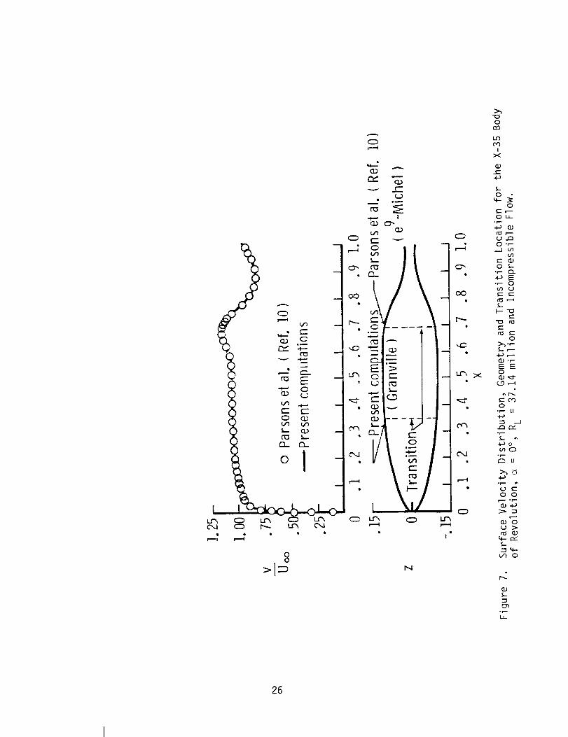
Another low-drag body called X-35 (configuration e) studied by Parsons
et al. (ref. 10) was also analyzed. The predicted surface-velocity distribution
agrees very well with that presented in reference 10 (see fig. 7). Parsons
uses the Michel-e 9 correlation to predict boundary-layer transition. The
Michel-e 9 correlation provides a relation between R0 and Rs at transition
(ref. 21):
0.46R0 = 1.174 (I + 22400/Rs)R s (1)
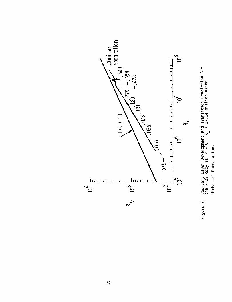
The results in figure 8 indicate that no catastrophic Tollmien-Schlichting
growth is predicted and transition due to laminar separation occurs at X/L =
0.68. Granville's transition criterion is more conservative for the X-35 body
with transition predicted at X/L = 0.35 for RL = 37.14 million. This discrepancy
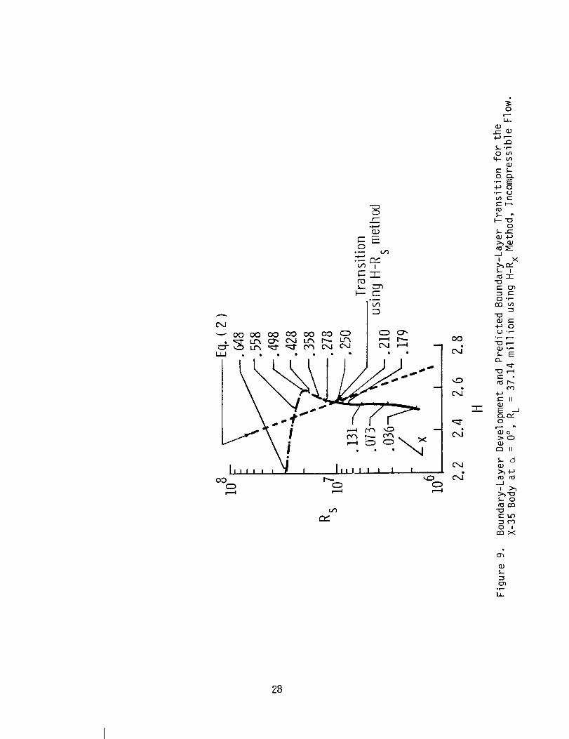
in the prediction of transition location has been further analyzed by applying
the H-R x boundary-layer transition criterion by Wazzan, Gazley and Smith (ref.
22) and also by performing a linear stability analysis of the laminar boundary
layer. The H-R x method correlates the boundary-layer shape factor H = 6*/0 and
Rs at transition as follows:
log[Rs(eg)] = -40.4557 + 64.8066 H - 26.7538 H2
(2)+ 3.3819 H3 for 2.1 < H < 2.8
The results in figure 9 show that according to this method boundary-layer
transition occurs at X/L = 0.25. The linear stability analysis of the laminar
boundary layer has been performed using the SALLY code (ref. 23). Input to this

program is provided by a modified version of the Harris finite-difference
boundary-layer code (ref. 24). In figure I0, the logarithmic disturbance
amplitude ratio or "n-factor" is plotted as a function of the nondimensional
axial distance X/L for a range of Tollmien-Schlichting disturbance frequencies.
The envelope of these curves shows that an n-factor of 9 is reached at X/L = 0.185,
while at X/L = 0.25 the n-factor is about 12.5. In summary, it appears that the
Michel-e 9 criterion as used by Parsons et al. (ref. I0) provides transition
results which are too optimistic.
Next, a representative business aircraft fuselage of fineness ratio about
6 (configuration f)was analyzed. Inviscid pressure distributions on the upper
and the lower surface were calculated and are presented in figure 11. Laminar-
turbulent transition prediction was made using Granville's criterion at a unit
Reynolds number of I million per foot (RL = 40.86 million) and it is indicated
in the figure (transition Reynolds number range is 4.1 million - 16.0 million).
It is to be noted that it is not possible to analyze these kinds of practical
nonaxisymmetric bodies by using axial singularity distributions. Furthermore,
the transition prediction assumed no three-dimensional boundary-layer stability
effects. While this assumption might limit the validity of the present transition
prediction, the value of that limit (say in terms of Reynolds number) is not
known. The validity of this prediction remains to be checked with experimental data.
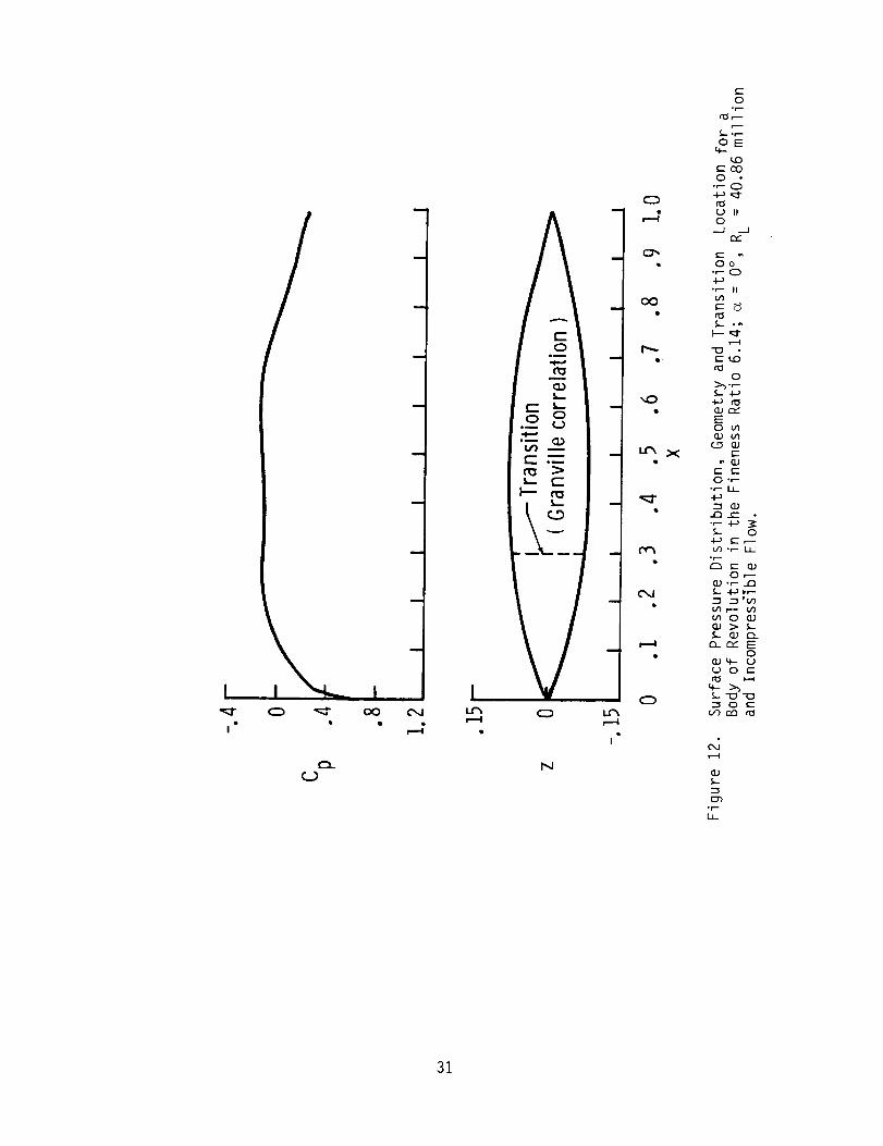
Finally a body of revolution whose maximum diameter and length (configuration
g) correspond to those of the representative business aircraft fuselage config-
uration (configuration f) is considered. Also this configuration can be
thought of as a special case obtained by setting the longitudinal camber equal
to zero in the more generalized configuration given by configuration f. Predicted
inviscid pressure distributions and transition location are presented in figure
12 for zero angle of attack.
10

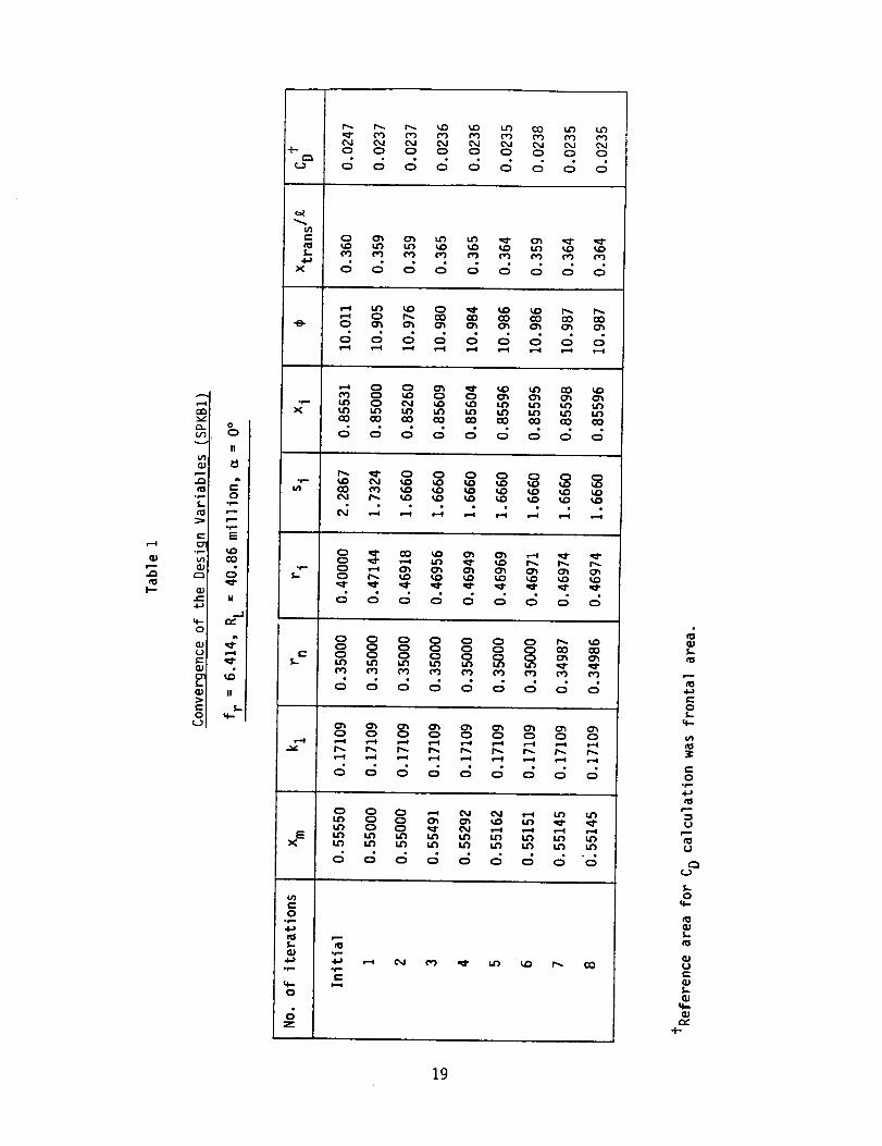
Results from the Design Procedure
Preliminary results obtained by the optimization procedure are discussed
through an example and are given in Table I. The analysis is for an angle of attack
of zero and the flow is assumed to be incompressible. Initially the
axisymmetric body is modeled by a set of initial values of the design para-
meters. The fineness ratio is fixed at 6.14 and the design Reynolds number
(based on length) RL is 40.86 million. The upper and the lower bounds of the
design variables are also input. In the present calculation profile drag
coefficient is chosen as the objective function to be minimized. The design
parameters at the end of each iteration are presented in Table I along with the
objective function. For the above example the design procedure converged at
the end of the 8th iteration. Since the initial values of the design variables
were not too far from the optimized design variables the process converged in
8 iterations. Judicious choice of the starting solution helps in achieving the
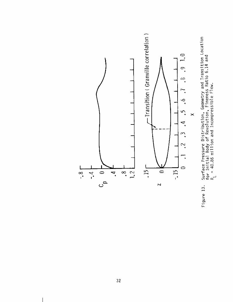
final optimized solution in a lesser number of iterations. The initial body
shape, given by the design parameters in the first row of Table I, is sketched
in figure 13. The pressure distribution for the body is also shown in the
figure. For this initial body the transition location was computed at X/L =
0.36. The improvements in the transition location through the next few
iterations along with the final converged value are indicated in Table I. We
see from Table I that the transition location is pushed further aft for the
final body shape and accordingly the drag is reduced. The final body shape
along with the pressure distribution are sketched in figure 14.
As explained earlier for computing the transition locations Granville's
criterion is used in the analysis. Since to date there exists no satisfactory
method to predict the transitional region on an axisymmetric body Granville's
criterion has been used in the optimization cycle. Since one can predict
growth of Tollmien-Schlichting waves downstream of the neutral point in the
ii
laminar boundary layer using linear stability analysis it is logical to include
it in the design process itself. But in view of the computational costs and
complexities, direct incorporation of the boundary-layer stability analysis in
the optimization procedurewasavoided and Granville's criterion was used for
predicting the transition.
Summary
Present airplane construction techniques result in the production of smooth
and accurate aerodynamic surfaces over which long runs of natural laminar
boundary-layer flow (NLF) can be obtained. A major portion of the past research
effort for achieving NLF has been focused on airplane lifting surfaces. However,
fuselage shaping to achieve considerable regions of NLF has received limited
attention. Recent introduction of business and commuter airplanes with low-
drag NLF lifting surfaces justifies study of the feasibility of NLF over fuselage
surfaces and thereby providing possibilities to decrease airplane profile drag.
In Phase I of the research effort, a low-order surface-singularity analysis
was used to obtain surface-pressure distribution over a selected number of
body shapes, including a representative nonaxisymmetric business-aircraft
fuselage. Using an integral boundary-layer method, predictions of transition
location and drag coefficient have been obtained for these body shapes. Exten-
sive runs of NLF are predicted over regions of favorable pressure gradient on
smooth surfaces of both axisymmetric and nonaxisymmetric bodies at low angles
of attack. A computational design procedure coupled with an aerodynamic analysis
program was developed to obtain a body shape with large extents of NLF and
minimum drag.
Comparisons of boundary-layer transition location predictions with limited
12

available experimental results for several bodies show poor correlation between
calculated and measured transition locations. Therefore, it is proposed to use
linear boundary-layer stability theory in the analysis and design of axisymmetric
bodies with favorable pressure gradients for considerable runs of NLF. Presently,
analytical tools are not available to calculate three-dimensional boundary-layer
velocity profiles and transition location accurately under nonaxisymmetric flow
conditions. Also, very limited high quality boundary-layer data under axisym-
metric and nonaxisymmetric flow conditions are available at high Reynolds
numbersto validate future developments in boundary-layer (stability) theory.
Based upon the results of Phase I it is recommendedthat a large-scale
high-Reynolds-number wind-tunnel experiment be conducted to obtain high-quality
boundary-layer velocity and transition data on bodies of revolution at various
angles of attack. The wind-tunnel experiment which would be designed using the
optimization method developed in Phase I and linear boundary-layer stability
theory, would provide needed experimental data for theory validation and also
demonstrate the achievability of extensive runs of NLFon commuterairplane and
business-jet type of fuselages.
13
References
I.
.
.
.
.
.
.
.
.
Runyan, L. James; Navran, Brent H.; and Rozendaal, Rodger A.: F-111 NaturalLaminar Flow Glove Flight Test Data Analysis and Boundary-Layer Stability
Analysis. NASA CR-166051, January 1984.
Holmes, Bruce J.; Obara, C. J.; and Yip, L. P.: Natural Laminar Flow
Experiments on Modern Airplane Surfaces. NASA TP-2256, June 1984.
Althaus, D.: Wind-Tunnel Measurements on Bodies and Wing-Body Combinations.
In Motorless Flight Research, 1972, NASA CR-2315, November 1973.
Younghans, J. L.; and Lahti, D. J.: Analytical and Experimental Studies ofNatural Laminar Flow Nacelles. AIAA Paper No. 84-0034, January 1984.
Quast, A.; and Horstmann, K. H.: Profile Design for Wings and Propellers.NASA TM-77785, November 1984.
Carmichael, B. H.: Underwater Drag Reduction Through Optimal Shape. In
Underwater Missile Propulsion, edited by L. Greiner, Compass Publications,
Inc., Arlington VA, 1966.
Dalton, C.; and Zedan, M. F.: Design of Low Drag Axisjnnmetric Shapes Bythe Inverse Method. Journal of Hydronautics, Vol. 15, Jan-Dec. 1981,
pp. 48-54.
Barger, R. L.: A Theoretical Investigation of Forebody Shapes Designed forNatural Laminar Boundary-Layer Flow. NASA TP-1375, January 1979.
Parsons, J. S.: The Optimum Shaping of Axisymmetric Bodies for Minimum
Drag in Incompressible Flow. Ph.D. Thesis, Purdue University, 1972.
10. Parsons, J. S.; Goods.n, R. E.; and Goldschmied, F. R.: Shaping of
Axisymmetric Bodies for Minimum Drag in Incompressible Flow. Journal of
Hydronautics, Vol. 8, No. 3, July 1974, pp. 100-107.
11. Pinebrook, W. E.: Drag Minimization on a Body of Revolution. Ph.D. Thesis,University of Houston, 1982.
12. Pinebrook, W. E.; and Dalton, C.: Drag Minimization on a Body of Revolution
Through Evolution. Computer Methods in Applied Mechanics and Engineering,
Vol. 39, 1983, pp. 179-197.
13. Young, A. D.: The Calculation of Total and Skin Friction Drags of Bodiesof Revolution at Zero Incidence. ARC R&M 1874, April 1939.
14. von Karman, Th.: Calculation of Pressure Distributions on Airship Hulls.NACA TM-574, 1930.
15. Hess, J. L.: The Unsuitability of Ellipsoids as Test Cases for Line-SourceMethods. Journal of Aircraft, Vol. 22, No. 4, April 1985, pp. 364-367.
14
16. Maskew, B.: Prediction of Subsonic Aerodynamic Characteristics - A Casefor Low-Order Panel Methods. Journal of Aircraft, Vol. 19, No. 2, Feb.1982, pp. 157-163.
17. Fox, C. H., Jr.: Experimental Surface Pressure Distributions for a Familyof Axisymmetric Bodies at Subsonic Speeds. NASA TM X-2439, December 1971.
18. Groth, E. E.: Boundary Layer Transition on Bodies of Revolution. NorthropAircraft Company, Report No. NAI-57-I162 (Contract AF33(616)-3168), BLC-IO0,July 1957.
19. Kaups, K.: Transition Prediction on Bodies of Revolution. Douglas AircraftCo., Report No. MDC J6530 (Contract No. N66001-74-C-0020), April 1974.
20. Hansen, R. J.; and Hoyt, J. G.: Laminar-to-Turbulent Transition on a Bodyof Revolution with an Extended Favorable Pressure Gradient Forebody.Transaction of the ASME, Vol. 106, June 1984, pp. 202-210.
21. Cebeci, T.; and Bradshaw, P: Momentum Transfer in Boundary Layers, HemispherePublishing Corporation, Washington, London, 1977.
22. Wazzan, A. R.; Gazley, C., Jr.; and Smith, A. M. 0.: H - Rx Method forPredicting Transition, AIAA Journal, Vol. 19, No. 6, June 1981, pp. 810-811.
23. Srokowski, A. J.; and Orszag, S. A.: Mass Flow Requirements for LFC WingDesign. AIAA Paper No. 77-1222, 1977.
24. Harris, J. E.; and Blanchard, D. K.: Computer Program for Solving Laminar,Transitional, or Turbulent Compressible Boundary-Layer Equations for Two-Dimensional and Axisymmetric Flow. NASA TM-83207, 1981.
25. Vanderplaats, G. N.: CONMIN: A FORTRAN Program for Constrained FunctionMinimization-User's Manual. NASA TM X-62282, August 1973.
15
Appendix
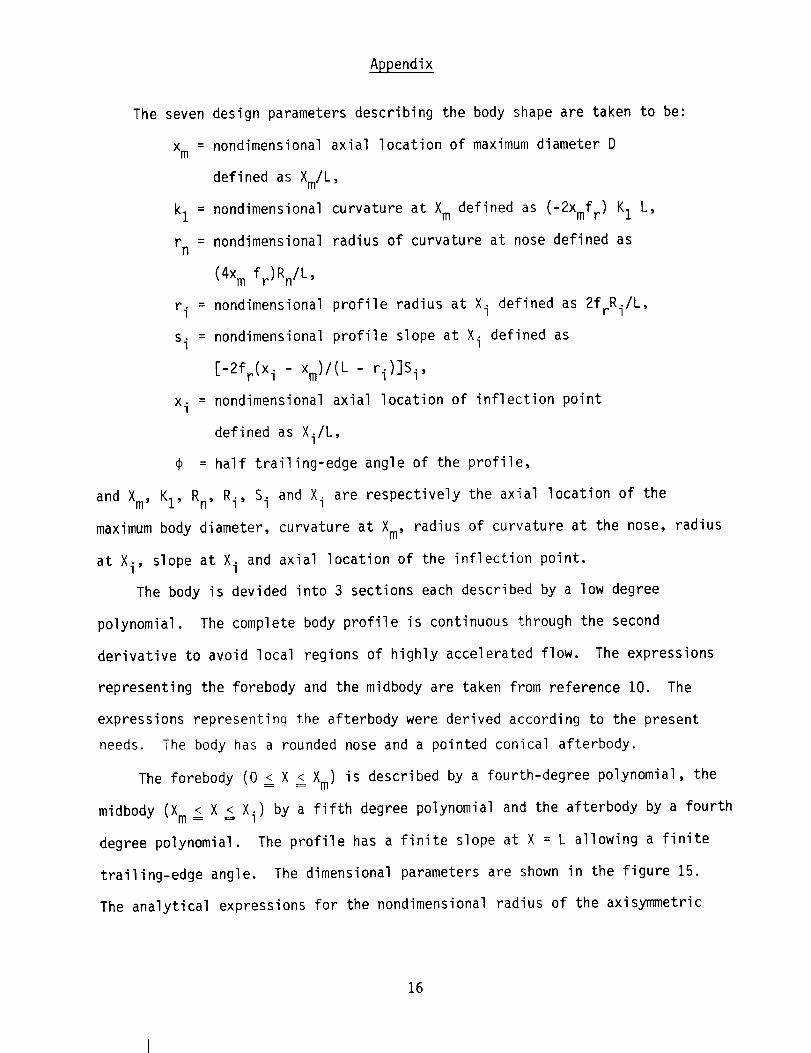
The seven design parameters describing the body shape are taken to be:
x m = nondimensional axial location of maximum diameter D
defined as Xm/L,
k I = nondimensional curvature at Xm defined as (-2Xmf r) KI L,
r n = nondimensional radius of curvature at nose defined as
(4x m fr)Rn/L,
r i = nondimensional profile radius at Xi defined as 2frRi/L,
s i = nondimensional profile slope at Xi defined as
[-2fr(X i - Xm)/(L - ri)]S i,
x i = nondimensional axial location of inflection point
defined as Xi/L,
@ = half trailing-edge angle of the profile,
and Xm, KI, Rn, Ri, Si and Xi are respectively the axial location of the
maximum body diameter, curvature at Xm, radius of curvature at the nose, radius
at Xi, slope at Xi and axial location of the inflection point.
The body is devided into 3 sections each described by a low degree
polynomial. The complete body profile is continuous through the second
derivative to avoid local regions of highly accelerated flow. The expressions
representing the forebody and the midbody are taken from reference I0. The
expressions representina the afterbody were derived according to the present
needs. The body has a rounded nose and a pointed conical afterbody.
The forebody (0 _ X _ Xm) is described by a fourth-degree polynomial, the
midbody (Xm _ X _ Xi) by a fifth degree polynomial and the afterbody by a fourth
degree polynomial. The profile has a finite slope at X = L allowing a finite
trailing-edge angle. The dimensional parameters are shown in the figure 15.
The analytical expressions for the nondimensional radius of the axisymmetric
16

body are given by
r(x): (_r)[rn Fl(X) + kI F2(x) + G(x)] I/2
for 0 _ X _ Xm (forebody)
where x = X/X m
Fl(X ) = -2x(x_l) 3
F2(x) = -x2(x - 1)2
G(x) = x2(3x 2 - 8x + 6)
For Xm_ X _ Xi (midbody)
r(x) = (2-_r) {ri + (1 - ri)[k I Fl(X ) + siF2(x ) + G(x)]}m
Xi - X
where x = (_ _ Xm)
1 x3(x _ 1)2FI(X) - 2
F2(x) = x - x3(3x 2 - 8x + 6)
G(x) = x3(6x 2 - 15x + 10)
k I : [(_-_) - 1] 2 klm (I - ri)
AI
A2
A3
A4
A5
A6
A7
A8
A9
AIO
All
For Xi =< X =< L (afterbody)
SiLX( x2(2x - 3)(x - I)r(x) = I - x 3) - Sia
+ x2(3x 2 - 8x + 6)
where
sia (xi - Xm)r i
(I - ri) (I - xi) si
A12
A13
17

2f r (x i - Xm) tan_
si L = { (I - r i)A14
fr = L/DA15
18
I--
"Z
_o
_J
I!
81*Im
E
ko00
O
I!
_D
II
s-
+-
Q_
s..4..)
X
)(
.r.-
EX
c-O
"3
0 0 0 _ 0 0 0 C, 0
0 0 0 0 0 0 0 0 0
• • . • • •
0 0 0 0 0 O 0 (_ CO
0 0 _ 0 0 0 _ 0 O
O O O C_
O O O C3 O O O C_ O
L
OS.
O°r--
_J
_J
(,J
Lo
q-
L
_J
_Jc_
19

L_
Z=,m
N
o_
E
-..I
Q,)
c--
!mm
0m
E
E:=
Z
e_
E
m
G.)
: Z
I
I""-
_.)
I_L
r-r-
E
og
("_
I./-
F'--I
(D
I'1
oo
,4
O
_'_ =D F_--. "_
oo oo 8
o
w _ c-"
o_
0T--
0T--
0Tin
o
el
m 0
0
wtm
o
°T--
%
!
T-"
o4-
rm
o_
o
o
• r-- _..
G,)
D_
2O

C.P I'_
E(D
0
¢-m
t-O
,m,=_
N
.N "_E
o_
>"'E "_' "_
-'s
0
°r-
E
J
%,f,-
,,_
Z
,f,..,.
E
1;=0_,,.,,.
.f-
,£,.
0
4--
0,f,,.,.
,m
0
c'-
0
_d
0_,,.
21

cc_
(13
e,,"
v
=_
c-
E_==
X
u'_ O U_ C3
_ " °
O
c-
OQj m=_
,=_
EO
=_
c-
CL)
eL)_==
IU'_ OC_
O
N
I
O
e
OO
®
u*%
e
e
cc_
C'J
X
or--In_
O .c-
O')
c-o _-•r-- (ZL
ca OU (.)O
c--t3O c-
•_- c-
_n O
E
r_
_- II
...A
O
(.._0O
o
"__ _
• r- r-
e'- _'1
.r--
22

ICO
!
0
Im
X _--
I
I
i Q Q •
r
N
0
Q
X
o
o
_o
E_o(I.iII___
C
c-
o,_I-
4_ ,ml-
°_..
°e-
ra C
m 0
(1) °e-_ 4-_
_ °_,-
4.-_--
_ 0
°_-.LL
23

l I
! !
Li
cj
GO
v
c-
EQm
X
©
t
c-O
,m
E0
c-
r_
IO0
00
c-
E,!
X
\
i
c-O
(.--
0
N
r-" °0
|m
C_-- O0
E- r-,.-0 •
t"--- o
i
0
i I
X
t_
*l---
Ix_
24

I
ql,I
m
I
(_) _ O0 C',.I
C",J
r_
u_ 0
I
N
O0
I".--
o
C',,.I8
r--,I
Y
°_.-
I.I-
25
0
-.-.- r-
N
o
I
x
q2
_z
i.a_
26
I
X
(_)5-
.r---
I.J--
27
0
c-
_E0
°m
_-r-
A
"--" O0 O0 O0 O0 O0 O0
\,... ? r rr_
llll , i , V , I,,II , , i i
(3O
_J
--r-
123
°r-
28

t--
III"
c;
Oil-I,
29

CD
r__I--
S-X5
O
G.Jc-
cy)c-O
(D
r_4--
EO
.._O
.._
(D
CY)
O
• Ioo
Q •
! I
I
m
Q.)
O
r_
G)
r---
C
c.O
c-O_
-r-.
r_s-
h-
Lur_ O,.---4
Q
oo
I
O
• X
0
0
r_uo
_ooo
.r-
l--- Or)
Cl.) _..-- ,---E m .l:::10 _...r--
or--- _
• r- I_r"_ > C
• r- O
23 4-_ r---_ _-or-
.r--
t.t._
3O
I
I
C.3
m
om
}--" tt_
I
N
o_--
31
I IO0 _'-
Q •I I
I
t
e
,m
om
e-
L
,Vo
N
w41
iQ
9
0
I
X
32

5- c-O 0
°_
c- r_0 .r--•r- :F=4--)
UGO
,g
°r--IJ--
33

q
0I_I_
e\
EX
lw
I
._.I
0
¢-
0
°r'-
N
°r-
E°r-
0
_J-C
c"0r_
$.-
(3,)
E
tO
N.-
0
c--
0
°r--
4--I])
_4
.r-
Ix-
34


1.Report No. ]2. Government AccessionNo. 3. Recipient'sCatalog No.
NASA CR-3970 h4. Title and Subtitle
Design of Fuselage Shapes for Natural Laminar Flow
7. Author(s)
S. S. Dodbele, C. P. van Dam, and P. M. H. W. Vijgen
5. Report Date
March 1986
6. Performing Organization Code
8. Performing Organization Report No.
10. Work Unit No.9. Performing Organization Name and Address
Vigyan Research Associates, Inc.
Hampton, VA 23666
12. Sponsoring Agency Name and Address
National Aeronautics and Space Administration
Washington, DC 20546
11. Contr_t or Grant No.
NASI-17926
13. Type _ Report and Period Cover_
Contractor Report
14. Sponsoring Agency Code
324-01-00
15. Supplement_y Notes
Langley Technical Monitor: Bruce J. Holmes
SBIR Phase I Final Report
S. S. Dodbele and C. P. van Dam: Vigyan Research Associates, Inc., Hampton, VA.
P. M. H. W. Vijgen: University of Kansas, Lawrence, Kansas.
16. Abstr_tRecent technological advances in airplane construction techniques and
materials allow for the production of aerodynamic surfaces without
significant waviness and roughness, permitting long runs of natural
laminar flow (NLF). The present research effort seeks to refine and
validate computational design tools for use in the design of axisymmetric
and nonaxisymmetric natural-laminar-flow bodies. The principal task of
the investigation involves fuselage body shaping using a computational
design procedure.
Under Phase I SBIR funding for this research, analytical methods were
refined and exploratory calculations conducted to predict laminar
boundary-layer behavior on selected body shapes. Using a low-order
surface-singularity aerodynamic analysis program, pressure distribution,
boundary-layer development, transition location and drag coefficient have
been obtained for a number of body shapes including a representative
business-aircraft fuselage. Extensive runs of laminar flow were predicted
in regions of favorable pressure gradient on smooth body surfaces. A
computational design procedure was developed to obtain a body shape with
mimimum drag having large extent of NLF. Some preliminary results from
the design efforts have been obtained and further work is underway.
17. Key Words(Suggestedby Authors(s))
Natural Laminar Flow
Fuselage Shape
Transition
19. Security Cl_sif.(ofthisreport)Unclassified
I
18. Distribution Statement
Unclassified - Unlimited
Subject Category 34
20. Security Cl_slf.(of this page) 21. N f Pages 122. PriceUnclassified _ A03
For sale by the National Technical Information Service, Springfield, Virginia 22161
NASA LangLey Form 63 {June 1985)NASA-Langley, 1986