nlight eclypse™ - i n s t a l l a t i o n g u i d e · acuit o o 30012 o 8005352465 acuitooo...
TRANSCRIPT

Acuity Brands | One Lithonia Way Conyers, GA 30012 Phone: 800.535.2465 www.acuitycontrols.com © 2014-2015 Acuity Brands Lighting, Inc. All rights reserved. 09/22/15 1 of 12
nLight ECLYPSE™ - I n s t a l l a t i o n G u i d e
Table of Contents 1.0 Introduction...............................................................................................................................................................................................2 1.1 Product Description.................................................................................................................................................................................2 1.2 General Installation Requirements.........................................................................................................................................................2 1.3 Device Marking Symbols........................................................................................................................................................................3 1.4 General Wiring Diagram.........................................................................................................................................................................3 1.5 Module Enclosure Dimensions...............................................................................................................................................................32.0 Mounting Instructions...............................................................................................................................................................................4 2.1 Mounting Positions.................................................................................................................................................................................4 2.2 DIN Rail-Mounted Installations...............................................................................................................................................................4 2.3 Assembly Order 2.4 Wall Mounted Installation......................................................................................................................................................................43.0 Power Supply Module (24V) Wiring..........................................................................................................................................................54.0 Power Supply Module (100-240 VAC) Wiring...........................................................................................................................................55.0 DIP Switch and Jumper identification and Configuration.........................................................................................................................66.0 nLight Interface Module............................................................................................................................................................................6 6.1 LED Blinking Patterns..............................................................................................................................................................................67.0 Communications Wiring........................................................................................................................................................................6,7 7.1 Wired Connections...................................................................................................................................................................................7 7.2 Wireless Connections...............................................................................................................................................................................7 8.0 Configuring the Controller.....................................................................................................................................................................7,8 8.1 Using the Factory-Default Hostname in a Web Browser..........................................................................................................................7

Acuity Brands | One Lithonia Way Conyers, GA 30012 Phone: 800.535.2465 www.acuitycontrols.com © 2014-2015 Acuity Brands Lighting, Inc. All rights reserved. 09/22/15 2 of 12
8.2 Using the Controller’s IP Address in a Web Browser................................................................................................................................7 8.3 Connecting to the Controller’s Configuration Web Interface...................................................................................................................89.0 BACnet MS/TP Communications Wiring....................................................................................................................................................810.0 Modbus RTU Communications Wiring.................................................................................................................................................8,9 11.0 Modbus TCP Communications Wiring.....................................................................................................................................................912.0 Addtional Information.............................................................................................................................................................................9 12.1 Maintenance.........................................................................................................................................................................................9 12.2 Disposal................................................................................................................................................................................................9 12.3 North American Emmissions Compliance.............................................................................................................................................9 12.4 Complementary Information................................................................................................................................................................913.0 Wifi Instructions...............................................................................................................................................................................10,11 13.1 Typical Mounting Scenarios................................................................................................................................................................10 13.2 Instructions for Ceiling Mount............................................................................................................................................................10 13.3 Instructions for NPT Mounting.......................................................................................................................................................10,11 13.4 Locations Tips......................................................................................................................................................................................11

Acuity Brands | One Lithonia Way Conyers, GA 30012 Phone: 800.535.2465 www.acuitycontrols.com © 2014-2015 Acuity Brands Lighting, Inc. All rights reserved. 09/22/15 3 of 12
1.0 Introduction
1.1 Product Description
This document describes the installation procedures for the nLight ECLYPSE. The nLight ECLYPSE provides time-based control of an nLight and/or XPoint Wireless network as well as acting as the IP interface for SensorView software. Consisting of a server module, power supply module, nLight network interface module, the nLight ECLYPSE expands the capacity and functionality of the Series 2 nLight Gateway with a native BACnet interface (optional) that is BACnet Technology Laborato-ries (BTL) listed as a BACnet Building Controller (B-BC). For more detailed information about the nLight ECPLYPSE and its capabilities please download the ECLYPSE User Guide.
1.2 General Installation Requirements
For proper installation and subsequent operation of the nLight ECLYPSE, pay special attention to the following recommendations:• Upon unpacking the product, inspect the contents of the carton for shipping damages. Do not install damaged modules.• Avoid areas where corroding, deteriorating or explosive vapors, fumes or gases may be present.• Ensure the mounting surface can support the controller, DIN rail, and any user-supplied enclosure.• Allow for proper clearance around the controller’s enclosure, and wiring terminals to provide easy access for hardware configuration and maintenance, and to
ventilate heat generated by the controller.• The controller’s mounting orientation must be horizontal with the controller’s back attached to a vertical wall surface. Orient the controller with the ventilation
slots and power supply input terminal block connectors towards the top to permit proper heat dissipation. When installed in an enclosure, select one that provi-des sufficient surface area to dissipate the heat generated by the controller and by any other devices installed in the enclosure. A metal enclosure is preferred. If necessary, provide active cooling for the enclosure.
• The controller’s datasheet specifies the power consumption (amount of heat generated), the operating temperature range, and other environmental conditions the controller is designed to operate under.
• Ensure that all equipment is installed according to local, regional, and national regulations.• If the controller is used and/or installed in a manner not specified by Acuity, the functionality and the protection provided by the controller may be impaired.

Acuity Brands | One Lithonia Way Conyers, GA 30012 Phone: 800.535.2465 www.acuitycontrols.com © 2014-2015 Acuity Brands Lighting, Inc. All rights reserved. 09/22/15 4 of 12
Any type of modification to any Acuity product will void the product’s warranty.
Take reasonable precautions to prevent electrostatic discharges to the controller when installing, servicing or operating the controller. Discharge accumulated static electricity by touching one’s hand to a well-grounded object before working with the controller.
1.3 Device Markings (Symbols)
Certain markings (symbols) can be found on the controller and are de-fined as follows:
Symbol DescriptionCE marking: the device conforms to the requirements of applicable EC directives.
Double Insulation marking: These controllers are built using double insulation.
Products must be disposed of at the end of their useful life according to local regulations.
Read the Hardware Installation Guide for more information.
For indoor use only.
UL marking: conforms to the requirements of the UL certification.
FCC marking: This device complies with FCC rules part 15, subpart B, class B.
Warning Symbol: Significant information required. Refer to the Hardware Installation Guide.
HIGH VOLTAGE Symbol: Direct contact will cause electrical shock or burn.
Alternating CurrentDirect Current
Line
Neutral
1.4 General Wiring Recommendations
Any type of modification to any Acuity product will void the product’s warranty.
• All wiring must comply with electrical wiring diagrams as well as national and local electrical codes.
• To connect the wiring to a device, use the terminal connectors. Use a small flat screwdriver to tighten the terminal connector screws once the wires have been inserted (strip length: 0.25’’ (6 mm), tightening torque 0.5 Nm).
• Keep wiring separate according to their function and purpose to avoid any ambient noise transmission to other wires. Use strapping to keep these wires separated. For example, keep power, hazardous volta-ge, SELV, network, and input wiring separate from each other.
For the Power Supply module: When connecting one wire to a control-ler’s terminal block clamping cage (pole), the wire must be between 18 and 14 gauge (0.82 and 2.1mm2 cross-sectional area). When connec-ting two wires to a controller’s terminal block clamping cage, both wires must be the same thickness, must be between 18 and 16 gauge (0.82 and 1.3mm2 cross-sectional area), and must be the same type (solid or stranded). Twist the wires together and insert then into the controller’s terminal block clamping cage. For any other wiring combination (mixed wire thickness, mixed solid and stranded conductors, more than three wires, wire thickness is out of range), twist the wires together and use a wire nut and a pig tail to connect to the controller’s terminal block connector as show below.
Controller
Wire Nuts
Terminal BlockConnector
Wire ConnectionsPigtails
Figure 2: Using a Wire Nut and Pigtail to Wire the Controller• Keep all wires away from high speed data transmission cables (for ex-
ample, Ethernet, etc.).• Keep input and output wiring in conduits, trays or close to the building
frame if possible.• Use the screws, wall anchors, and wire nuts included for wall mounting
and wiring.
1.5 Module Enclosure Dimensions
3.18" 80.82
18.540.73
21.080.83
3.33" 84.47
0.4" 1.093.57" 90.67
Inches Millimeters
Inter-Connection Gap: 0.01" 0.40
5.13" 130.29
0.06" 1.44
4.74" 120.31
0.39" 9.98 Front Back
Figure 3: Control Module

Acuity Brands | One Lithonia Way Conyers, GA 30012 Phone: 800.535.2465 www.acuitycontrols.com © 2014-2015 Acuity Brands Lighting, Inc. All rights reserved. 09/22/15 5 of 12
80.82
18.39
21.13
1.44Back
103.65
133.03
120.31
11.13
97.33Front
0.40Inter-Connection Gap:
Millimeters
Figure 5: Power Supply Module (100 to 240 VAC)
2.95 [74.99]
4.74 [120.31]
3.20 [81.17]
3.18 [80.82]
0.73 [18.54]
0.83 [21.08]
Inter-Connection Gap: 0.01 [0.40]
Front Back0.06 [1.44]
4.80 [121.75]
Inches [Millimeters]
Figure 6: nLight Network Interface Module2.31" 58.56
Figure 7: Side view - all modules
2.0 Mounting InstructionsEach module can be mounted on a DIN rail for fast installation and easier maintenance. Each module also has two pre-molded mounting holes allo-wing the module to be mounted in a panel or on a wall. The nLight ECLYPSE can be DIN rail mounted inside NEMA Type 1 enclosure.
Ensure that the mounting surface can support the controller, DIN rail, and any site-supplied enclosure.
Horizontal Mounting Position:Required for DIN rail mountingRequired for wall mounting
Vertical Mounting Position:Is Forbidden
Figure 8: Permitted Mounting Positions
2.2 Assembly OrderModules are connected in a left to right order, starting with the Power Supply module, then the Server module, and lastly the nLight network interface mo-dule.
2.3 DIN Rail-Mounted Installation 1. Clip the modules onto the DIN rail mounted inside the enclosure in the
assembly order.
Figure 9: DIN rail-mounted controller2. Slide the modules together so that the side connectors of each module
are firmly mated with the adjoining module. Use DIN rail clips to keep the row of modules well secured together and to prevent the movement of any module along the DIN rail. Certain modules come with DIN rail clips in the box.
3. To detach the module from the DIN rail, separate the module from any other module located on either side. Use a flat screw driver to pull down on the release clip located at the bottom center of the module and pull it off the DIN rail, bottom first.
2.4 Wall Mounted Installation Only the nLight ECLYPSE using a 24V Power Supply module can be mounted on a wall. The 100-240VAC power supply module must NOT be installed on the wall, only in the NEMA Type 1 enclosure.
The nLight ECLYPSE modules should be mounted on a wall one module at a time. The first module of the assembly to be mounted should be the one to the very left (the 24V power supply). Once this module has been attached to the wall, connect the next module on the right so that the side connectors are firmly coupled and the modules are aligned straight. Now attach this module to the wall. Repeat until all modules are mounted in a row.
1. Before mounting a module, separate the front assembly from the back plate of each module to be mounted: push the two latches up to unlock a module’s front assembly as shown below.
• Separate the front and back base by gently pulling the front assembly off of the back base, thereby separating the electrical connectors bet-ween the two halves.
2.1 Mounting PositionsThe controller‘s mounting orientation must be horizontal with the controlle‘s back attached to a verical wall surface.

Acuity Brands | One Lithonia Way Conyers, GA 30012 Phone: 800.535.2465 www.acuitycontrols.com © 2014-2015 Acuity Brands Lighting, Inc. All rights reserved. 09/22/15 6 of 12
Figure 10: Latches to Unlock a Module’s Front Assembly 2. Once the front assembly has been removed, use the back plate’s mounu-
ting holes to mark the location of any holes that need to be drilled.
Figure 11: Typical Mounting Holes 3. Drill the holes. 4. Clean the surface and mount the module using a No. 8 slotted hex, size:
1/4” or equivalent mounting hardware appropriate to the wall.
Figure 12: Appropriate Mounting Hardware (field supplied) 5. To lock a module’s front assembly in place, attach the front assembly to
the module’s back base by closing any gull-wing front assemblies (if ap-plicable) and pushing the two latches down.
3.0 Power Supply Information
3.1 Power Supply Module (24V) Wiring
Voltage: 24VAC/DC; ± 15%, Class 2
For terminal block connector wiring best practices, see General Wiring Re-commendations.
This is a Class 2 Product. Use a Class 2 transformer only (rated between 60 and 100VA at 24VAC) for each power supply module.
A separate transformer rated at 60 VA minimum must be used for each pow-er supply module (24V) for it to operate at full capacity. Choose a transformer that can supply both the needs of the power supply (60VA) and any other 24VAC loads such as connected wireless adapters: add up the maximum po-wer consumption of all loads and multiply this sum by 1.3.
Use an external fuse on the 24VAC side (secondary side) of the transformer, as shown in the figure below, to protect all modules against power line spi-kes and mis-wiring.
Maintain consistent polarity when connecting controllers and devices to the transformer. One terminal on the secondary side of the transformer must be connected to the building’s ground. Ensure that the 24V COM terminal of the power supply is connected to the grounded transformer secondary connecti-on.
24VA
C
AC PowerSource(Mains)
Fuse: 4AMax. Fast
Acting
Elec
trica
lSy
stem
Gro
und
Equi
vale
nt
24VD
C
Fuse: 4AMax. Fast
Acting
+ –
DC PowerSource
Figure 13: Power Supply Module (24V) Power wiring
3.2 Power Supply Module (100-240VAC) Wiring
Voltage: 100-240 VAC; +10%/-15%; 50/60 Hz
Overvoltage Category II - 2.5 kV
For terminal block connector wiring best practices, see General Wiring Re-commendations.
Always conform to the wiring regulations in effect in your jurisdiction.
The power supply module (100-240VAC) must be connected to the mains using the provided detachable connector.
The power wires must be between 18 AWG (1 mm²) and 16 AWG (1.5 mm²). Use wire with appropriate insulation for this application.
Operating, handling, or servicing this product must be performed by trained personnel only. Turn off power before any kind of servicing.Risk of electric shock. Do not open. This product has no user-serviceable parts inside. When power has been disconnected, dangerous residual internal voltages may still be present. Return this unit to Acuity for maintenance or repair.
Acuity Brands | One Lithonia Way Conyers, GA 30012 Phone: 800.535.2465 www.acuitycontrols.com © 2014-2015 Acuity Brands Lighting, Inc. All rights reserved. 09/22/15 7 of 12
Equi
vale
nt
Neutral
AC PowerSource (Mains)
Fast ActingFuse
Line
Disconnect
AC PowerSource (Mains)
CircuitBreaker
Neutral Line
Figure 14: Power Supply Module (100-240VAC) Line-To-Neutral Power Wirl-
ing
DIP Switch and Jumper Identification and Configuration 4.0
Server ModuleThe Server module has the following onsite configurable jumpers or DIP swit-ches located inside the cover. Orient the circuit board as shown in the figure below.
* Factory-default positions
SUBNET EOLTermination
HOST SUBNET
SEC RS-485PRIRESET
EOL Off(Disabled)*
EOL On(Enabled)
RS-485 EOLTermination
EOL Off(Disabled)*
EOL On(Enabled)
* Factory-default positions
SUBNET EOLTermination
HOST SUBNET
SEC RS-485PRIRESET
EOL Off(Disabled)*
EOL On(Enabled)
1 2 3ON
OFF*
EOLBIAS + BIAS -
RS-485 EOL Termination Option Configuration
Figure 15: Server module jumper, DIP Switch, and reset button locations
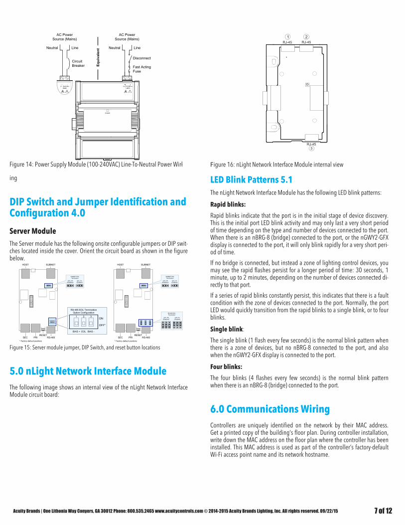
5.0 nLight Network Interface Module The following image shows an internal view of the nLight Network Interface Module circuit board:
RJ-45 RJ-45
RJ-453
Figure 16: nLight Network Interface Module internal view
LED Blink Patterns 5.1The nLight Network Interface Module has the following LED blink patterns:
Rapid blinks:
Rapid blinks indicate that the port is in the initial stage of device discovery. This is the initial port LED blink activity and may only last a very short period of time depending on the type and number of devices connected to the port. When there is an nBRG-8 (bridge) connected to the port, or the nGWY2-GFX display is connected to the port, it will only blink rapidly for a very short peri-od of time.
If no bridge is connected, but instead a zone of lighting control devices, you may see the rapid flashes persist for a longer period of time: 30 seconds, 1 minute, up to 2 minutes, depending on the number of devices connected di-rectly to that port.
If a series of rapid blinks constantly persist, this indicates that there is a fault condition with the zone of devices connected to the port. Normally, the port LED would quickly transition from the rapid blinks to a single blink, or to four blinks.
Single blink:
The single blink (1 flash every few seconds) is the normal blink pattern when there is a zone of devices, but no nBRG-8 connected to the port, and also when the nGWY2-GFX display is connected to the port.
Four blinks:
The four blinks (4 flashes every few seconds) is the normal blink pattern when there is an nBRG-8 (bridge) connected to the port.
6.0 Communications WiringControllers are uniquely identified on the network by their MAC address. Get a printed copy of the building’s floor plan. During controller installation, write down the MAC address on the floor plan where the controller has been installed. This MAC address is used as part of the controller’s factory-default Wi-Fi access point name and its network hostname.

Acuity Brands | One Lithonia Way Conyers, GA 30012 Phone: 800.535.2465 www.acuitycontrols.com © 2014-2015 Acuity Brands Lighting, Inc. All rights reserved. 09/22/15 8 of 12
Bar Code
ID: MAC AddressModel: ECY-S1000
For example, for a MAC Address of : 76:a5:04:cd:4a:d1The factory-default name for the Wi-Fi access point is ECLYPSE-CD4AD1The factory-default hostname is eclypse-cd4ad1.local
Label
Figure 17: Finding the Controller’s MAC Address
There are two methods to connect to the controller: wired (Ethernet connection) or wireless (when the ECLYPSE Wi-Fi Adapter is connected to the controller).
6.1 /Wired Connection Network connections can be daisy-chained.
To Router /Next IP Device
To Next IPDevice
RJ-45Connector
Cat 5eNetworkCable
Figure 18: Communications Wiring
6.2 Wireless Connection Once the ECLYPSE Wi-Fi Adapter has been connected to the controller, a Wi-Fi hotspot becomes available that allows you to connect to the controller’s confi-guration Web interface with your PC.
On your PC’s wireless networks, look for an access point named ECLYPu-SE-XXYYZZ where XXYYZZ are the last 6 hexadecimal characters of the controlr-ler’s MAC address (see above). The default password for the wireless network is: eclypse1234
7.0 Configuring the ControllerAny of the following methods can be used to connect to the controller’s inter-face in order to configure it:• Using the controller’s factory-default Hostname in the Web browser• Using the controller’s IP address in the Web browser
7.1 Using the Factory-default Hostname in a Web Browser Controllers have a factory-default hostname that you can use instead of an IP address to connect to it. The hostname can be used in a Web browser’s ad-dress bar or in the EC-gfxProgram’s Connect to screen. When installing the latest version of EC-gfxProgram and your PC does not have the Bonjour sern-vice installed, a link to install the Bonjour service is provided. The Bonjour service must be installed on your PC to allow your PC to discover controllers by their hostname.
If your PC is unable to resolve the controller’s hostname, you must connect your PC to the controller through Ethernet or Wi-Fi so that your PC only sees the controller network. For example, in this case, your PC must be disconnec-ted from all other networks such as a corporate network or the Internet. If necessary, temporarily disconnect your PC’s network cable from its Ethernet port.
The controller’s factory-default hostname is eclypse-xxxxxx.local where xxxxxx is the last 6 characters of the MAC address printed on a sticker located on the side of the controller. See above.
For example, the sticker on the side of a controller shows that its MAC ad-dress is 76:a5:04:cd:4a:d1. Connect to the controller’s Web interface as fol-lows:1. Open your Web browser.2. In the Web browser’s address bar, type https://eclypse-cd4ad1.local and
click go.3. Login to the controller. Then set the controller’s configuration parameters
in the controller’s configuration Web interface. See Connecting to the Controller’s Configuration Web Interface.
7.2 Using the Controller’s IP Address in a Web Browser Connect to a controller through its IP address as follows:
For a Wi-Fi Network Connection:1. Open your Web browser.2. In the Web browser’s address bar, type 192.168.0.1 (the controller’s facs-
tory-default wireless hotspot IP address) and click go.3. Login to the controller. Then set the controller’s configuration parameters
in the controller’s configuration Web interface. See Connecting to the Controller’s Configuration Web Interface.
£ For an Ethernet Network Connection: You must know the controller’s current IP address (from the DHCP server for example).
1. Open your Web browser.2. In the Web browser’s address bar, enter the controller’s IP address and
click go.3. Login to the controller. Then set the controller’s configuration parameters
in the controller’s configuration Web interface. See Connecting to the Controller’s Configuration Web Interface.

Acuity Brands | One Lithonia Way Conyers, GA 30012 Phone: 800.535.2465 www.acuitycontrols.com © 2014-2015 Acuity Brands Lighting, Inc. All rights reserved. 09/22/15 9 of 12
7.3 Connecting to the Controller’s Configuration Web Interface
At the first connection to an ECLYPSE Controller you will be forced to change the password to a strong password for the admin account to protect access to the controller.
In Network Settings, configure the controller’s network parameters so that they are compatible with your network. It is important to create new user ac-counts with strong passwords to protect the controller from unauthorized ac-cess. Remove the factory default admin account as this is a commonly known security breech (only the password for this user account needs to be compro-mized)
8.0 Communication Protocols
8.1 BACnet MS/TP Communications Wiring
For optimal performance, use 24 AWG (0.65 mm) stranded, twisted pair shielded cable. The BACnet MS/TP communication wire is polarity sensitive and the only acceptable topology is to daisy-chain the cable from one control-ler to the next.
• As shown in the figure below:• The first and last daisy-chained BACnet MS/TP devices must have their
EOL resistors enabled / installed. All other devices must have their EOL resistor disabled (default factory setting). See the figure below.
• The first and last daisy-chained BACnet MS/TP devices must have their BIAS enabled. All other devices must have their BIAS disabled (default factory setting). See the figure below. Note that the BIAS settings for BACnet MS/TP controllers that do not have a specific setting to enable / disable BIAS usually means that the BIAS is enabled when the EOL resis-tors are enable
• Isolate all shields with electrical tape so there is no exposed metal that can touch ground or other con-ductors.
• The shield of the data bus must be connected to the electrical system ground at only one point – usually at one end of the bus as shown below.
• Connect no more than 50 devices to a BACnet MS/TP data bus.
Use the Server Module’s RS-485 port to connect to a trunk of BACnet MS/TP devices. This port must be configured in the controller’s Web interface prior to use.
Server
Figure 19: BACnet MS/TP Communications Wiring
When inserting multiple wires into a terminal-block connector, ensure to pro-perly twist wires together prior to insertion.
8.2 Modbus RTU Communications Wiring BACnet MS/TP and Modbus RTU communications are made by connecting di-rectly to separate RS-485 ports.
Furthermore, Modbus TCP devices can be integrated by connecting them to the controller’s IP network.
For optimal performance, use 24 AWG (0.65 mm) stranded, twisted pair shielded. The Modbus RTU communication wire is polarity sensitive and the only acceptable topology is to daisy-chain the cable from one controller to the next.
As shown in the figure below:• The first and last daisy-chained Modbus RTU devices must have their
EOL resistors enabled / installed. All other devices must have their EOL resistor disabled (default factory setting).
• The first and last daisy-chained BACnet MS/TP device must have their BIAS enabled. All other devices must have their BIAS disabled (default factory setting). See the figure below. Note that the BIAS settings for BACnet MS/TP controllers that do not have a specific setting to enable / disable BIAS usually means that the BIAS is enabled when the EOL resis-tors are enabled

Acuity Brands | One Lithonia Way Conyers, GA 30012 Phone: 800.535.2465 www.acuitycontrols.com © 2014-2015 Acuity Brands Lighting, Inc. All rights reserved. 09/22/15 10 of 12
• When the Modbus RTU data bus is connected to a fol-lowing device, twist data bus shields together.
• Isolate all shields with electrical tape so there is no exposed metal that can touch ground or other con-ductors.
• The shield of the data bus must be connected to the electrical system ground at only one point – usually at one end of the bus as shown below.
• Connect no more than 50 devices to a Modbus RTU data bus.
Use the Server Module’s RS-485 port to connect to a trunk of Modbus RTU devices.
Server
Figure 20: Modbus RTU Communications Wiring
If inserting multiple wires in the terminals, ensure to properly twist wires to-gether prior to inserting them into the terminal connectors.
8.3 Modbus TCP Communications Wiring Connect Modbus TCP devices to the same IP subnet the controller is using. This connection can be made by connecting the Modbus TCP device to an Ethernet port on the Server Module with a Cat5e network cable for example (see Wired Connection).
9.0 Additional Information
9.1 Maintenance Turn off power before any kind of servicing.
Regular Maintenance
Each controller requires minimal maintenance, but it is important to take note of the following:• Clean the outside of the controller by polishing it with a soft dry cloth.• Retighten terminal block connector screws annually to ensure the wires
remain securely attached.
9.2 Disposal
The Waste Electrical and Electronic Equipment (WEEE) Directive sets out regu-lations for the recycling and disposal of products. The WEEE2002/96/EG Di-rective applies to standalone products, for example, products that can functi-on entirely on their own and are not a part of another system or piece of equipment.
For this reason Acuity products are exempt from the WEEE Directive. Nevert-heless, Acuity products are marked with the WEEE symbol , indicating de-vices are not to be thrown away in municipal waste.
Products must be disposed of at the end of their useful life according to local regulations and the WEEE Directive.
9.3 North American Emissions Compliance
United States
Changes or modifications not expressly approved by Acuity could void the user's authority to operate the equipment.
This equipment has been tested and found to comply with the limits for a Class B digital device, pursuant to Part 15 of the FCC Rules. These limits are designed to provide reasonable protection against harmful interference in a residential and commercial installation. This equipment generates, uses and can radiate radio frequency energy and, if not installed and used in accordance with the instructions, may cause harmful interference to radio communications. However, there is no guarantee that interference will not occur in a particular installation. If this equipment does cause harmful interference to radio or television reception, which can be determined by turning the equipment off and on, the user is encouraged to try to correct the interference by one or more of the following measures:
Reorient or relocate the receiving antenna.
Increase the separation between the equipment and receiver.
Connect the equipment into an outlet on a circuit different from that to which the receiver is connected.
Consult the dealer or an experienced radio/TV technician for help.
Canada
This Class (B) digital apparatus meets all the requirements of the Canadian Interference-Causing Equipment Regulations.
Cet appareil numérique de la Classe (B) respecte toutes les exigences du Règlement sur le matériel brouilleur du Canada.
9.4 Complementary Information
The Power Supply Module (100-240VAC) is designed for type 1 action and type 1.b action. The EMC immunity test passed using 230 VAC and 0.5 A. The Ball pressure Test temperature was 167°F (75°C) for the Enclosure and 257°F (125°C) for the Connectors. The SELV must not exceed 42 VDC. The maxi-mum accessible voltage is 19 VDC. All connecting cables must be perma-nently installed with X-type anchors. All cables must have insulation rated for 176°F (80°C) or higher. These products are classified as integrated electronic operation control devices. SELV is guaranteed by reinforced insulation.

Acuity Brands | One Lithonia Way Conyers, GA 30012 Phone: 800.535.2465 www.acuitycontrols.com © 2014-2015 Acuity Brands Lighting, Inc. All rights reserved. 09/22/15 11 of 12
10.0 Wifi Antenna Instructions Product Description The adapter adds two extra features to the nLigth ECLYPSE. The first being the ability to wirelessly connect multiple ECLYPSE controllers together to form a Wi-Fi Mesh, to allow them to communicate with one another. The second feature is the ability to connect directly to the controller via ENVYSIONTM.
The Wi-Fi Mesh feature is very useful when wanting to commission an installation with more than 1500 devices. If this limit is exceeded, multiple ECLYPSES can be connected together via ethernet or the wireless adapter. The wireless adapter would be used in situations where the building materials or layout make it difficult, or it is inconvenient to connect the controllers with a wired connection.The hotspot is useful because it allows the commissioner to connect directly to the controllers. A more detailed version of this section can be found in the ECLYPSE User Guide.
10.1 Typical Mounting Scenarios
The nLight ECLYPSE Wifi antenna is typically mounted in one of three common scenarios, these include: • Suspended Ceiling Mount• Mounting Bracket • Metal Panel/Utility Box
Whichever mounting scenario is chosen, the wireless adapter should be 16” (41 cm) or more away from any network communication devices and not too close to the actual nLight ECLYPSE. The wireless adapter connects directly to the ECLYPSE via the USB port. You are supplied with a 6’ cable. This cable cannot be made any longer and must not be modified.
10.2 Instructions for Ceiling Mount
1. Use 1.75” (44m) hole saw to create a mounting hole position.2. Disassemble the wireless adapter: remove the snap-fitted cap, disconnect
the dongle, unscrew the collar, and remove the washer. 3. Fit the rubber washer and slot onto the cable assembly. Align the washer
and slot with the key (refer to illustration for clarification) 4. Screw the collar onto the assembly. 5. From the top of the ceiling panel, fit the cable assembly through the mount-
ing hole and hold it in place. 6. On the bottom of the ceiling panel, slide the lower flange onto the collar
until the wireless adapter is firmly held in place. 7. Fit the dongle into the cable assembly’s connector. 8. Align the cap with the dongle’s profile and snap it onto the collar.9. Connect the USB cable assembly’s USE jack to one of the controller’s Host
USB ports. 10. Finish up the installation by securing the cable assembly at regular intervals
to the building structure.
See Figure 1 for illustration
Figure 1: Assembly Drawing: Mounting of an ECLYPSE wireless adapter on a
10.3Instructions for NPT Mounting
1. Remove the 3/4 inch electrical panel knockout or use a 01.115” (26.9 to 32.5mm) hole punch to create a mounting hole position
2. Disassemble the wireless adapter: remove the snap-fitted cap, disconnect the dongle, unscrew the collar, and remove the rubber washer.
For the Power Supply Module (100-240VAC): Risk of electric shock. Do not open. This product has no user-serviceable parts inside. When power has been disconnected, dangerous residual internal voltages may still be present. Return this unit to Acuity for maintenance or repair.

Acuity Brands | One Lithonia Way Conyers, GA 30012 Phone: 800.535.2465 www.acuitycontrols.com © 2014-2015 Acuity Brands Lighting, Inc. All rights reserved. 09/22/15 12 of 12
3. Fit the rubber washer onto the cable assembly. Align the slot with the key. See figure 2 for clarification.
4. From the inside of the electrical enclosure or on the construction surface, pull the cable from the ECLYPSE to the wireless adapter.
5. Plug-in the USB connector into the USB host slot on the nLight ECLYPSE.
Figure 2: Assembly Drawing: Mounting of an ECLYPSE wireless adapter on a metal enclosure or consutruction surface
Do not mount wireless adapter inside of metal enclosures.
10.4 Location Tips for nLight ECLYPSES using Wi-Fi Adapter
When installing the wireless adapter, it is important to ensure that distances and obstructions do not impede transmission. Metallic parts, such as reinforcement in walls, machinery, office furniture, etc. are major sources of field strength dampening. Furthermore, supply areas and elevators shafts should be considered as complete transmission screens. See figure below
For transmission obstructions, one way to get around an obstruction, such as a duct, is to place the wireless adatper on the side of the obstruction that is nearer to the coordinating wireless device, even if the controller is on the opposite side of the obstruction. But always keep in mind that the wireless adapter performs best when it is away from metal objects or surfaces. Two common sources of the wireless obstructions in the field are when the wire-less adapter is placed in a high angle of incidence and when two wireless adapters are placed along the same wall. A steep angle of incidence may cause a signal to run through more obstructions than realized, dampening the signal. Therefore it is preferable that the transmission be arranged so that it travels straight or perpendicuarly through the obstruction. See Figure 3.
Linked wireless adapters should not be mounted on the same wall or plane. Radio waves are subject to interfering reflections. It is always best to place the linked wireless antennas on the side or opposite walls. See Figure 4.
Figure 3: High Angle of Incidence
Figure 4: Wall Reflectance