nl9 ch08 2nd - learningcentre.nelson.comlearningcentre.nelson.com/student/9780070723634/... · a...
TRANSCRIPT

Two small batteries can be put into a CD player to bring you the thundering bass and screaming guitar of your favourite band. Batteries can also provide
power for digital cameras, wristwatches, and flashlights. How is the electrical energy that is stored in a battery transformed into
so many other forms of energy? The energy in the battery is carried through hundreds of pathways inside an electrical device. Some of the pathways may produce sound, while pathways in other devices may produce motion, heat, or light. When you press “play” on a CD player like the one shown here, the pathways transform the silent chemical energy stored in the batteries into sound energy.
Electricity is not a modern discovery. However, today’s technological society depends on being able to control and use electricity in many ways in many different devices. In this chapter, you will learn how electrical energy is transferred and transformed.
248 MHR • Unit 3 Characteristics of Electricity

Chapter 8 Ohm’s law describes the relationship of current, voltage, and resistance. • MHR 249
What You Will Learn
In this chapter, you will • explain how electric current results from
separation of charge and the movement of electrons
• apply the laws of static charge to electron flow in a circuit
• define voltage, current, and resistance• draw circuit diagrams using appropriate
symbols• distinguish between potential and
kinetic energy; static electricity and current electricity; and conventional current and electron flow
Why It Is Important
Every time you turn on a television, computer, or flashlight, or turn the key to start a car engine, you complete an electric circuit. You use electric circuits to control how electrical energy is transferred.
Skills You Will Use
In this chapter, you will• measure voltage and current using
appropriate equipment• calculate resistance using current and
voltage data• model electric circuits using circuit
diagrams
FOLDABLES TM
Reading & StudySkills
Make the following Foldable and use it to take
notes on what you learn in Chapter 8.
STEP 1 Use nine sheets of lined paper. Leave one sheet whole. Cut two lines off the bottom of the second sheet.
STEP 2 Cut 4 lines off the third sheet, 6 lines off the fourth sheet, 8 lines off the fifth sheet, 10 lines off the sixth sheet, 12 lines off the seventh sheet, 14 lines off the eighth sheet, and 16 lines off the ninth sheet.
STEP 3 Align the sheets along the top edge from shortest to longest and staple along the top.
STEP 4 Label the top section with the chapter title, and label each of the following tabs with the eight points listed under the “What You Will Learn” and “Skills You Will Use.”
Summarize As you read the chapter, summarize what you learn under the appropriate tabs.
Chapter 8Ohm’s Law describes therelationships of current,voltage, and resistance.
Electric CurrentLaws of Electric ChargeCurrent and ResistanceDraw Circuit Diagrams
Energy, Electricity, Currents, Electron FlowMeasure Voltage and Current
Determine ResistanceUse Ohm’s Law

When unlike charges are moved farther apart, they gain electric potential energy.
Electric potential difference is the change in potential energy per coulomb of
charge. Voltage is the common name for electric potential difference and is
measured in volts (V). Electrical energy depends on the amount of charge and the
voltage. Electrochemical cells, or batteries, are a common source of voltage. We use
voltmeters to measure potential difference.
What do a charged storm cloud and batteries have in common? They both separate positive and negative charges. Lightning is an uncontrolled burst of electrical energy and can cause power outages, injuries, loss of life, and fires. A battery can provide a steady, controlled flow of electricity. Which would you choose as a source of energy for a CD player?
A battery is a combination of electrochemical cells connected together (or a single electrochemical cell). Electrochemical cells convert chemical energy into electrical energy stored in charges. Electrochemical cells are commonly called cells or batteries. In a battery, chemical energy separates the positive and negative charges. Examine Figure 8.1. The battery terminals are the end points where we make a connection. Extra electrons accumulate on one of the battery terminals, making it negatively charged. The other terminal has lost these electrons and is therefore positively charged. When the battery is connected to a CD player, electrons can travel through the wires and into the player. The electrons’ stored electrical energy is transformed into sound energy.
Electric Potential Energy and Voltage
8.1
Key Termsbatteryelectric potential energy electrochemical cells electrodeselectrolyte energypotential differencevoltvoltage
250 MHR • Unit 3 Characteristics of Electricity
Figure 8.1 The purpose of an electrochemical cell or battery is to give electrons stored electrical energy.
+ + + + + + + +
+ + + + + +
– – – – – – – – – – – –
– –

A Penny for a Battery8-1A Find Out ACTIVITY
Chapter 8 Ohm’s law describes the relationship of current, voltage, and resistance. • MHR 251
Did You Know?
You may be familiar with AA, AAA, C, and D batteries. Have you ever seen a B battery? B batteries were used in portable radios more than 80 years ago. They are no longer used in today’s technology and therefore are not
common.
In this activity, you will build an electrochemical cell from common household materials.
Materials • aluminum foil• paper towel• penny• voltmeter• vinegar
What to Do1. Place a small piece of aluminum foil (5 cm � 5 cm)
on the desk.
2. Place a piece of paper towel (2.5 cm � 2.5 cm) on the aluminum foil.
3. Place a clean copper penny on the dry paper towel.
4. Using a digital voltmeter, touch the aluminum foil with one lead and touch the penny with the other lead. Observe and record the reading on the voltmeter.
5. Remove the paper towel and soak it in vinegar. Place it back between the aluminum foil and the penny. Repeat step 4.
6. Clean up and put away the equipment you have used.
What Did You Find Out?1. (a) How did the voltmeter reading in step 5 differ
from the reading in step 4?
(b) What do you think caused the difference?
2. (a) Vinegar is a weak acid. If you did not have vinegar, what other similar liquid do you think would have had the same result?
(b) Explain why you chose this liquid.
3. Suppose you were to cover your penny with a paper towel soaked in vinegar and then add an identical stack of aluminum, paper towel soaked in vinegar, and penny. If you touched one lead on the bottom piece of aluminum foil and one lead on the top penny, what reading would you expect on the voltmeter? Explain.
4. What is another question about electrochemical cells that you could investigate using these materials?
Go to Science Skill 7 to learn more about how to use a voltmeter.
Science Skills
Using the voltmeter
Electric Potential EnergyEnergy is the ability to do work. Kinetic energy is energy a moving object has because of its motion. Potential energy is the energy stored in an object. The electrical energy stored in a battery is called electric potential energy because the electrons have stored energy and the ability to do work after they leave the battery.
If you stretch a spring and hold it, the energy in the spring is stored. This is an example of potential energy. The energy stored in the spring will not be released until you let go. Likewise, in order for the electrons to lose their stored electrical energy, the battery must be connected to a device. When you connect a battery to a light bulb, the electric potential energy is “released” as the electrons move through the wire inside the bulb and the electrons’ energy is converted into heat and light energy.

252 MHR • Unit 3 Characteristics of Electricity
Did You Know?
Nearly 20 years before Volta invented the battery, the Italian scientist Luigi Galvani noticed that a frog’s muscle would twitch when touched by two different metals. Galvani believed that the muscle tissue contained “animal electricity.” Volta later proved that the source of the potential difference was produced by the two different metals, not by the frog’s muscles.
Figure 8.4 Even though the stairs are the same height in A and B, more work is done in B. Therefore, there is more potential energy in B.
Electric Potential DifferenceYou may recall from section 7.1 that charge is measured in coulombs. The amount of electric potential energy per one coulomb of charge is called the potential difference or voltage. The unit for measuring potential difference is the volt (V). This unit was named in honour of Alessandro Volta (Figure 8.2), an Italian physicist who invented the battery (Figure 8.3).
Figure 8.3 In 1799, Volta invented a “voltaic pile” battery, alternating zinc and copper disks separated by pieces of fabric soaked in salt water.
Figure 8.2Alessandro Volta (1745–1827)
Comparing Potential Energy and Potential DifferenceYou might compare potential energy and potential difference with climbing a staircase. When you climb a flight of stairs, your body has done work (Figure 8.4). The work you have done is now potential energy. If you had climbed the same set of stairs with a heavy backpack, you would have done more work. As a result, you and the backpack would have more potential energy. The potential energy thus depends on the height of the stairs and the amount of mass moved to the top. You can think of the potential difference in a battery as being like the height of the stairs. The amount of charge separated in a battery is like the mass moved up the stairs. The potential energy in the battery is due to both the potential difference (volts) and the amount of charge that has been separated (coulombs). The amount of potential energy a battery can output dependsnot only on how much voltage the battery has but also on how much charge that battery can separate. Even though C, D, AA, and AAA batteries all have a potential difference of 1.5 V, the battery that can separate the most charge would have the greatest potential energy. The energy that charge possesses is dependent on the amount of charge and the voltage.
A voltmeter is a device that measures the amount of potential difference between two locations of charge separation. When you place the connecting wires of a voltmeter across the + and – terminals of a battery, the voltmeter displays the battery’s voltage.
A
B

positive terminal
plastic insulator
positive terminal
negative terminal
moist paste
carbon rod
negative terminal battery solution
lead plate
wet cell
lead-dioxideplate
partition
dry cell
Chapter 8 Ohm’s law describes the relationship of current, voltage, and resistance. • MHR 253
Did You Know?
The voltage across a muscle cell in your body is about 70 millivolts. A millivolt (mV) is one
thousandth of a volt.
Figure 8.5 Chemical reactions in batteries produce a voltage across the positive and negative terminals.
Producing VoltageWe can classify batteries into two groups: dry cells and wet cells (Figure 8.5). Dry cells are the batteries in devices like flashlights, portable CD players, and watches. Wet cells are commonly used in cars, motorcycles, and electric wheelchairs. Both types of batteries produce voltage in a similar way.
A battery has two terminals called electrodes. The electrodes are usually made of two different metals but can be a metal and another material. The electrodes are in an electrolyte, which is a substance that conducts electricity. In a dry cell, the electrolyte is a moist paste; in a wet cell, the electrolyte is a fluid. Figure 8.6 shows an electrochemical cell that uses a zinc and a copper electrode. The acidic electrolyte attacks the zinc electrode and pulls atoms off the zinc. But the zinc atoms leave electrons behind on the electrode, and the electrode becomes negatively charged. At the same time, chemical reactions pull electrons off the copper electrode. Therefore, the copper electrode has a positive charge. Because there is an opposite charge on each electrode, there is a potential difference (voltage) between the two electrodes.
The amount of voltage that is produced in an electrochemical cell depends on the types of metal and the electrolyte used. Most modern electrochemical cells can produce 1.5 V or 2.0 V. For example, a 12 V car battery could consist of six 2.0 V cells or eight 1.5 V cells connected together.
Figure 8.6 An electrochemical cell requires two different electrodes (usually metals) and an electrolyte.
Find Out Activity 8-1B on page 255Conduct an Investigation 8-1C on page 256
Suggested Activity

254 MHR • Unit 3 Characteristics of Electricity
Many Sources of Electrical Energy An electrochemical cell or battery changes chemical energy into electrical energy by separating charge. Other forms of energy can also be used to separate charge and provide electrical energy.
Friction
Rubbing two materials together, such as acetate and paper, or rubber and wool, can separate charge. These separated charges now have electrical energy. Some of the work done by rubbing is converted into the electrical energy stored in the separated charge.
Piezoelectric crystals
A barbecue lighter has no battery inside to produce the electric spark. The electricity comes from a tiny crystal. When certain types of crystals, such as quartz, are squeezed, positive and negative charges are separated on either side of the crystal. A small hammer in the lighter hits the piezoelectric crystal, generating a burst of thousands of volts of electricity. The prefix “piezo-“ means pressure or push.
Photo-electrochemical cells
Solar panels and many calculators use photo-electrochemical cells or solar cells as a source of power. Photo-electrochemical cells are made of semi-conducting material such as silicon. When light hits the cell, some of the light energy breaks electrons off the surface of the cell. These separated electrons now have the electrical energy needed to operate a calculator, a phone booth, or the International Space Station.
Thermocouples
A thermocouple is a device used to transform heat energy into electrical energy. A thermocouple consists of a loop of two wires of different metals joined at both ends. If one end of the loop is heated or cooled, charge is separated and a voltage is created across the thermocouple. Individual thermocouples can produce only a small amount of electrical energy. If a larger amount of electricity is needed, several thermocouples must be joined together. We use a thermocouple in a kitchen oven to control the temperature.
Generators
The electricity that enters most of our homes is produced by a generator. Generators work on the principle that when a wire moves close to a magnet or a magnet moves close to a wire, a voltage is created across the wire. All that is needed is an energy source to provide the wire or the magnet with the necessary motion. In Newfoundland and Labrador, we use hydroelectric energy, the energy of water to generate electrical energy.
Table 8.1 Examples of Electrical Energy Sources

Using the Voltmeter8-1B Find Out ACTIVITY
In this activity, you will use a voltmeter to measure the potential difference of different batteries.
Safety
• Be sure the positive lead is connected to the positive terminal of the battery and the negative lead is connected to the negative terminal.
Materials • voltmeter• various batteries: AA, AAA, lantern battery, watch
battery, 9.0 V battery
What to Do1. Make a table to record your observations. Give your
table a title.
2. Attach the leads of the voltmeter to one of the batteries. Be sure that the positive (�) lead of your voltmeter is connected to the positive (�) terminal of the battery and the negative (�), or common, lead of the voltmeter is connected to the negative (�) terminal of the battery. Record the voltage in your data table.
3. Repeat step 2 with the remaining batteries.
What Did You Find Out?1. Why is it important to connect the positive lead of
the voltmeter to the positive terminal of the battery?
2. When measuring an unknown voltage, we start with the meter set to a high voltage scale and then decrease the scale. Explain the purpose of starting with a higher setting.
3. Does the physical size of the battery indicate how much voltage it has? (That is, do larger batteries have higher voltages than smaller batteries?) Explain.
Reading Check1. What device uses chemical energy to give charges electric potential
energy?2. What is the definition of energy?3. How is kinetic energy different from potential energy?4. What is another name for electric potential difference?5. What two factors determine the
amount of energy in a cell?6. What is the purpose of a
voltmeter?7. What are two groups of
batteries?8. How is an electrode different
from an electrolyte?9. What are five energy sources that
can produce electrical energy?
Chapter 8 Ohm’s law describes the relationship of current, voltage, and resistance. • MHR 255
Are electric cars new or old? Electric cars powered by batteries were more popular than gas-powered cars in the early 1900s. Environmental concerns and the cost of oil have helped promote the development of new electric and hybrid vehicles. To find out more about battery technology in electric and hybrid vehicles, go to www.discoveringscience9.ca.
Go to Science Skill 7 for information on using a voltmeter.
Science Skills

Fruit Battery8-1C
SkillCheck
• Measuring
• Classifying
• Communicating
• Evaluating information
In this investigation, you will determine the factors that produce potential difference in an electrochemical cell.
QuestionWhat materials are needed to make a voltage-producing electrochemical cell?
Procedure
Part 1
1. Copy the following table into your notebook. Give your table a title.
2. Select one piece of fruit. Carefully insert two aluminum strips into the fruit. The two metal strips should be about 2 cm apart and parallel to each other.
Safety
• Be careful of sharp edges when inserting the metal strips into the fruit.
• Ensure that all lab materials are handled and disposed of using proper techniques.
Materials• various fruits• 2 aluminum strips• voltmeter• 2 zinc strips• 2 iron strips• 2 copper strips• steel wool • 250 mL beaker • water
Metal 2
Aluminum Zinc Iron Copper
Aluminum
Zinc
Iron
Copper
256 MHR • Unit 3 Characteristics of Electricity
Go to Science Skill 7 to learn more about how to use a voltmeter.
Science Skills
Step 3 Touch the leads from the voltmeter to the two strips.
Met
al 1

Conduct an INVESTIGATION
Inquiry Focus
3. Touch the leads from the voltmeter to the two strips. You may find that the voltage fluctuates. Count 5 s from when you first started measuring the voltage. Record the voltage at 5 s in your data table.
4. Remove one of the aluminum strips from the fruit and insert the zinc strip. Be sure to use the same slit that the original strip was in. Repeat step 3.
5. Continue steps 3 and 4 until you have done all the combinations of metal strips and the data table contains all the measured voltages.
Part 2
6. Identify the combination of metals that produced the highest voltage. Wash the two strips so that there is no fruit juice on them. Use the steel wool to clean the strips. Fill a 250 mL beaker with 100 mL of clean water.
7. Place the metals identified in step 6 in the beaker of water. Place them so they are parallel and about 2 cm apart.
8. Connect the voltmeter to the two strips just as you did in step 3. Observe the reading on the voltmeter.
9. Clean up and put away the equipment you have used.
Analyze1. In Part 1, what combination of metals produced the
highest voltage?
2. In Part 1, what combination of metals produced the lowest voltage?
3. In general, how did the voltage produced by two similar metals in Part 1 compare to the voltage produced when the two metals were different types?
4. Why was it important to use the same openings in the fruit each time?
5. In Part 2, how did the voltage produced by the two metals in water compare to when the metals were in the fruit? Give a possible explanation for this result.
Conclude and Apply1. What materials are needed to produce a high
voltage in an electrochemical cell?
2. Suppose that you needed to produce a higher voltage from a fruit battery. Suggest two ways that you could do this.
3. Batteries purchased from stores are used for devices like MP3 players and cellphones. List several reasons why fruit batteries would not be a good replacement for these store-bought batteries.
4. List at least 10 different uses for a battery.
Chapter 8 Ohm’s law describes the relationship of current, voltage, and resistance. • MHR 257

Electric Fish: The Shocking TruthVarious species of fish have specialized organs that can produce small amounts of voltage. Most of these fish use the voltage to sense their environment and for navigation and communication. The Pacific electric ray (Torpedo californica) shown below is found in the coastal waters of British Columbia. These fish produce voltages of about 50 V, which is enough voltage to stun their prey and protect themselves from large animals.
The most famous of the strongly electric fish is the electric eel, found in the waters of South America. The electric eel (Electrophorus electricus) shown below is not an eel at all. Rather, it belongs to a species of fish known as knifefish. Electric eels can grow up to 2.5 m long and have a mass of 25 kg. Electric eels can produce almost 10 times more voltage than the Pacific electric ray. How do electric eels generate these large voltages?
Almost 80 percent of an eel’s length is its electricity-producing tail. The eel’s tail consists of an organ containing thousands of electricity-producing cells called electrogenic cells. Each cell acts like a small battery with one side of the cell containing a positive charge and the opposite side a negative charge. These cells can produce only a small voltage of approximately 100 mV (0.1 V). But because the cells are positioned one after the other, like batteries in a flashlight, the voltage of each cell is added to the next. The result is the ability for the electric eel to produce a 500 V shock. This electrical discharge only lasts approximately 2 ms (0.002 s) but is sufficient to kill small fish nearby. A single discharge from an electric eel’s tail would stun a human or large animal but is usually not enough to kill.
Water is a good conductor of electricity. How is the electric eel able to shock nearby fish yet not shock itself? When the electric eel produces a 500 V shock, the electric current spreads in all directions through the water. Since a large portion of the current dissipates into the water through the eel’s skin, very little current actually flows through the eel’s internal organs. Therefore, creatures near the eel get shocked rather than the eel itself.
258 MHR • Unit 3 Characteristics of Electricity
Cross-sectionof an electric eel
The electric organs makeup most of thefish’s body.
musclesused forswimming
muscles
spinal cord

Checking Concepts1. What is the amount of energy per unit of
charge called? 2. Explain how potential difference in a battery is
similar to a staircase.3. What is another word for potential difference?4. What two factors determine the output energy
of a battery? 5. What device could you use to measure
potential difference?6. A battery is a common source of electrical
energy. Describe two other methods of producing electrical energy.
Understanding Key Ideas7. Explain how an electrochemical cell produces a
potential difference across its terminals. 8. A student conducts an experiment of building
an electrochemical cell. She places two strips of silver in a beaker of lemon juice. She then connects a voltmeter to the two strips. Predict what voltage the voltmeter will measure. Explain your prediction.
Chapter 8 Ohm’s law describes the relationship of current, voltage, and resistance. • MHR 259
A 9.0 V battery that you might use in a television remote control is very small compared to the 12 V battery in a car. Could you use two 9.0 V batteries connected together (18 V) to start a car? Explain why or why not.
Pause and Reflect
Current electricity is the flow of charged particles in a complete circuit. The unit for
measuring electric current is the ampere (A), which is defined as one coulomb of
charge passing a given point per second. An ammeter is a device used to measure
current. To have a continuous flow of charge, the circuit must contain at least one
source of voltage. In a circuit, electric potential energy is transformed into other
forms of energy. Circuit diagrams are drawn to represent electric circuits.
Electric Current8.2
Key Termsamperes circuit diagrams current electricityelectric circuitelectric currentelectric load
260 MHR • Unit 3 Characteristics of Electricity
Did You Know?
A typical tiny computer chip contains more than a million circuits.
Lighting It Up
8-2A
In this activity, you will investigate ways to make a circuit using a battery, conducting wire, and a light bulb.
Safety • If the wire becomes hot, disconnect it immediately.
Materials • D cell
• 10 cm of insulated wire with both ends bare
• one 2.0 V flashlight bulb
What to Do1. Using the flashlight bulb, wire, and battery, try to
make the bulb light up. Once you are successful, disconnect the battery. Make a sketch of how these three materials were connected.
2. Rearrange the three materials and find a different way to make the bulb light up. Make a sketch of this second circuit.
3. Make a sketch that includes the three objects in such a way that the bulb will not light up. Then, using the materials, check if your sketch is correct.
What Did You Find Out?1. Explain the difference between the sketches in steps
1 and 2 and the sketch in step 3.
2. Which of your sketches show a complete circuit?
3. Give an example of something in your home or community that represents a complete circuit.
Find Out ACTIVITY
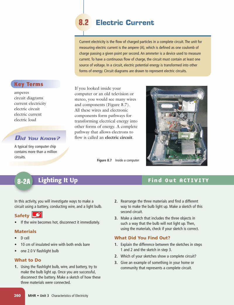
If you looked inside your computer or an old television or stereo, you would see many wires and components (Figure 8.7). All these wires and electronic components form pathways for transforming electrical energy into other forms of energy. A complete pathway that allows electrons to flow is called an electric circuit.
Figure 8.7 Inside a computer

Chapter 8 Ohm’s law describes the relationship of current, voltage, and resistance. • MHR 261
Energy Around a CircuitAny device that transforms electrical energy into other forms of energy is called an electric load. Some examples of a load are a light bulb, a buzzer, a heater, and a motor. Figure 8.8 illustrates a simple circuit containing a battery, conducting wires, and a buzzer. Chemical energy in the battery gives the electrons on the negative terminal electric potential energy. These electrons are attracted to the positive terminal of the battery. Since there is a pathway for them to travel, electrons leave the negative terminal and are pushed by the energy from the battery through the conducting wires to the buzzer. In the buzzer, the electrons’ electric potential energy is transformed into sound energy. Electrons travel back to the battery through the complete circuit.
You can picture a waterslide (Figure 8.9) to help you think about an electric circuit.
E. Once the person stops in the pool at the bottom, he has no potential energy, and he is ready to climb the stairs again. Electrons in a circuit have zero electric potential energy after passing through the load.
A. The person at the bottom of the stairs represents an electron. The stairs are like the battery because they provide potential energy. In order for the person to gain potential energy, he must climb the stairs.
B. Once the person is at the top of the stairs, he has potential energy. The number of stairs he climbed represents the voltage of the battery.
C. As the person walks horizontally along the top platform, he is not changing his potential energy. This is similar to the electrons passing through the conducting wire.
D. The person’s potential energy drops when he descends the slide. As he slides, his potential energy is transformed into other forms of energy resulting in a potential energy or voltage drop. This is like the electrons passing through the load.
Figure 8.9 One difference between the swimmer and the electron is that a single electron does not keep going around the circuit, whereas the swimmer may make many return trips down the slide!
battery
buzzer
��
electronflow
Figure 8.8 A battery provides the voltage that allows the electrons to travel through the circuit.

262 MHR • Unit 3 Characteristics of Electricity
Circuit Components and DiagramsEven the most complex circuits are made of only four basic types of parts or components:• Source: the source of electrical energy• Conductor: the wire through which electric current flows• Load: a device that transforms electrical energy into other forms of
energy• Switch: a device that can turn the circuit on or off by closing or
opening the circuit
Suppose that you needed to have someone build an electrical circuit for you. You could describe what you needed using words, you could make an artist’s sketch of the circuit, or you could take a photograph. Alternatively, you could make a circuit diagram. Circuit diagrams are diagrams that use symbols to represent the different components of the circuit. Figure 8.10 shows some common circuit symbols used in circuit diagrams.
Figure 8.11 Drawing a circuit diagram is a quick and accurate way to model an electric circuit.
Figure 8.10 Circuit symbols help simplify complex circuits.
Circuit diagrams give an organized representation of the actual circuit. In order to make your circuit diagrams simple to read, be sure to meet the following criteria.• Draw your diagrams using a ruler.• Make all connecting wires and leads straight lines with 90º
(right-angle) corners.• If possible, do not let conductors cross over one another.• Your finished drawing should be rectangular or square.
Figure 8.11 shows a sketch of a simple circuit and its circuit diagram. Check that the diagram meets all four of the criteria listed above.
conducting wire
cell
voltmeter
battery
bulb
open switch
closed switch
+ –
+ –
Reading Check1. What other forms of energy can electrical energy be converted into
by a load? 2. What is an electric circuit?3. Explain how electrons in a circuit are like people on a waterslide.4. What are the four basic components of a circuit?5. What is the purpose of a circuit diagram?
Find Out Activity 8-2C on page 265Conduct an Investigation 8-2E on page 267
Suggested Activities

Drawing Circuit Diagrams8-2B
In a closed circuit, there can be no breaks in the path of electrons. An open circuit does not allow a flow of electrons because there is a break in the path. In this activity, you will draw and analyze circuit diagrams and decide which are open and which are closed.
What to Do1. For each of the following circuit illustrations, draw its
corresponding circuit diagram.
What Did You Find Out?1. Which circuit(s) are closed circuits?
2. Which circuit(s) are open circuits?
3. In any of your closed circuits, identify the device that
(a) is the source of electric potential energy
(b) converts the electrical energy to other forms
Think About It
Chapter 8 Ohm’s law describes the relationship of current, voltage, and resistance. • MHR 263
Electrons Are So PushyIn the circuits you have analyzed so far in this section, a battery supplies the energy to push electrons. Electrons are pushed from the negative terminal of the battery, along conducting wires through a load, such as a light bulb, and end up on the positive terminal of the battery. As soon as the battery is connected to the circuit, and the circuit is closed, electrons in every part of the circuit are pushing. That is why the light bulb goes on immediately.
This concept is similar to water in a hose connected to a tap, as shown in Figure 8.12. If the hose is already filled with water, as soon as you turn on the tap, water flows from the other end of the hose. The electrons leaving the negative terminal push the electrons ahead of them, just like water leaving the tap pushes on the water in front. You may remember from Chapter 7 that electrons do not need to touch in order to push other electrons. Electrons apply an action-at-a-distance force.
Current Electricity and Static ElectricityRecall from Chapter 7 that static electricity is charge that remains stationary on an insulator. The charge in a battery is not an example of static electricity, even though the charge remains very nearly fixed on the battery terminals when the battery is not connected to a closed circuit. Once a battery is connected to a complete circuit, charge will flow continuously through the circuit. The continuous flow of charge in a complete circuit is called current electricity.
Did You Know?
On average, electrons travel only about 0.5 mm/s in a circuit.
circuit A circuit B
circuit C
Figure 8.12 Electrons are pushed through a circuit in a similar way to how water is pushed through a hose.

264 MHR • Unit 3 Characteristics of Electricity
Current: The Measure of FlowYou might have used the term “current” to describe the flow of water. How does the current in Exploits River compare to the current in a small stream? Even though the water in the stream might move faster, the total volume of water in the Exploits River passing a point every second would be greater (Figure 8.13).
Figure 8.13 The volume of water flowing in the Exploits River (A) is greater than that of a stream (B). Therefore the river is said to have more current.
Scientists think about electric current as charge flowing in a conductor. Electric current is defined as the amount of charge passing a point in a conductor every second. Electric current is measured in amperes (A). This unit is named in honour of the French physicist André-Marie Ampère who studied the relationship between electricity and magnetism (Figure 8.14). Small currents are measured in milliamperes (mA); 1.0 A�1000 mA. An ammeter is a device used to measure the current in a circuit. An ammeter symbol on a circuit diagram looks like this:
Conventional CurrentIn 1747, Benjamin Franklin wrote about charged objects as being electrified “positively” and “negatively,” meaning that the positively charged objects contained more electric fluid (a greater, or positive amount) than the negatively charged objects (a lesser, or negative amount). This suggests that whenever electricity flows, it moves from positive to negative. Notice that a flow of charge from positive to negative is the opposite of the idea that we use today. For historical reasons, Franklin’s idea is named conventional current. The concept of conventional current is still used to describe and calculate potential difference in a circuit. The concept of electron flow to describe current was not accepted by scientists until the late 1800s, after the discovery of the electron.
Find Out Activity 8-2D on page 266
Suggested Activity
Figure 8.14 André-Marie Ampère (1775–1836)
A B

Pushing Electrons8-2C
When a battery is connected to a circuit, electrons in the conductor “push” or repel the other electrons nearby. The force between electrons is an action-at-a-distance force. In this activity, you will make a model for the motion of electrons in an electric circuit.
Materials • 6 plastic drinking straws
• 3 bar magnets
What to Do1. Using the straws as rollers, line up the magnets as
shown in the illustration. Make sure the north and south ends of the magnets are oriented as shown.
2. Carefully push the end magnet and observe the motion of the other two magnets.
What Did You Find Out?1. In a short paragraph, explain how this model
demonstrates the motion of electrons in a circuit.
2. Your finger provided the “push” to start the magnets moving. In an electric circuit, what device “pushes” the electrons through the circuit?
3. Suppose the magnets of this model were replaced with wooden blocks the same size as the magnets. Why would the wooden block model not be as useful a model as the magnet model?
Find Out ACTIVITY
Carefully observe what happens to the magnets.
Chapter 8 Ohm’s law describes the relationship of current, voltage, and resistance. • MHR 265
Reading Check1. From which terminal of a battery are electrons pushed?2. When a battery is connected to a circuit, all the electrons
throughout the circuit immediately start to move. How is this possible considering that most of the electrons in the circuit are far from the battery?
3. Why is the charge in a battery not an example of static electricity?4. What is the difference between static electricity and current
electricity?5. Define electric current.6. What are the units of electric current?7. What is the purpose of an ammeter?
The design of a computer chip that contains millions of electric circuits is an example of nanotechnology. Nanotechnology is technology on a very small scale, usually of one micron or less. Find out more about nanotechnology and electrical components. Start your search at www.discoveringscience9.ca.

Find Out ACTIVITY Measuring Current8-2D
In this activity, you will construct a circuit from a circuit diagram and use an ammeter to correctly measure current. If you need to convert the units for the current, remember that 1.0 A � 1000 mA.
Safety
• Make sure that the positive terminal of the ammeter is connected to the positive terminal of the battery, and the negative terminal of the ammeter is connected to the negative terminal of the battery.
• Never connect an ammeter directly across the terminals of a battery.
• There must be a load, like a light bulb, in the circuit to limit the flow of electrons.
• If the wires get hot, disconnect them immediately.
Materials • 1.5 V cell• various flashlight bulbs (1.5 V, 3.0 V, 6.0 V)• connecting wires• knife switch• ammeter
What to Do1. Copy the following table into your notebook. Give
your table a title. State a hypothesis about the relationship between the voltage of a light bulb in a circuit and the resulting current.
2. Using one of the light bulbs, connect the circuit as shown in the circuit diagram below.
3. Close the switch briefly and measure the current. Open the switch. Record the measurement in your data table.
4. Repeat steps 2 and 3 with the remaining light bulbs.
What Did You Find Out?1. (a) Which circuit had the largest current?
(b) Which circuit had the smallest current?
2. Why is it important to connect the positive lead of the ammeter to the positive side of the battery?
3. What is the purpose of the switch in this circuit?
4. When you measure an unknown current, you should start with the meter set to a large current scale and then decrease the scale. Explain the purpose of starting with a higher setting.
5. Predict the resulting current in your circuit if a light bulb with double the voltage of your highest voltage light bulb were used.
266 MHR • Unit 3 Characteristics of Electricity
Go to Science Skill 7 for information on using an ammeter.
Science Skills
In step 2, connect the circuit but leave the switch open.
Bulb Type (V) Measured Current (mA)

Criteria• Your circuit needs to
represent: - battery - electrical load - conducting wires - electrons• You must show how energy
is transformed by passing through the load.
• Electrons need to flow through your circuit for at least a minute or two.
• Your props are limited to a few small objects, such as tennis balls or bean bags.
Make a Model Circuit8-2E
SkillCheck
• Communicating
• Modelling
• Explaining systems
• Working co-operatively
Conduct an INVESTIGATION
Problem-Solving Focus
Chapter 8 Ohm’s law describes the relationship of current, voltage, and resistance. • MHR 267
Using models to explain an idea or concept is a key skill in science. In this activity, you will make a human model of an electric circuit.
ProblemHow can you design and build a human model of an electric circuit?
Design and Construct1. Meet together with group members and make a group flowchart or other
drawing of what happens in an electric circuit. Include as much detail as possible.
2. Discuss how the group could model the circuit. Be sure to include everyone’s ideas and input.
3. Decide whether you will need any simple props.
4. Practise your presentation and refine your model.
5. Perform your presentation for other groups.
Make a human model to represent electrons flowing in an electric circuit.
Evaluate1. How did your group show the change in potential energy in different parts of
the circuit?
2. How did your group show how energy was transformed?
3. What was the most difficult part about making a human model of an electrical circuit?
4. In what ways was your model an inaccurate representation of an electric circuit?
5. How could you refine your model based on ideas from other groups’ presentations?

The Faraday CageMost commercial airplanes avoid turbulent thunderstorms by flying over them or around them. But even with these precautions, it is estimated that every commercial airplane in Canada is hit by lightning at least once a year. How is it that the passengers and equipment on these planes avoid being damaged by this huge voltage? The answer to this was already known in 1836, long before planes were even invented.
Michael Faraday (1791–1867) was a brilliant chemist and physicist. During his studies of electricity, Faraday realized that excess charges were spread evenly over a conducting surface. Faraday
hypothesized that if an object were totally enclosed by conducting material, any excess charge placed on the surface would not have an effect on the object inside. Every point on the conducting surface would be at the same electric potential and therefore there would be no potential difference (voltage) inside the enclosure.
To test his hypothesis, Faraday built a room covered with metal foil. A large Van de Graaff generator was used to apply a “lightning bolt” to the room. Inside the room, Faraday held an electroscope to detect static charge. As Faraday had predicted, the large voltage applied to the exterior of the room had no effect on objects inside the room. An enclosure of conducting material is now called a Faraday cage.
Since airplanes have a complete outer covering of conducting metal, they act as a Faraday cage. The charge from a lightning strike spreads evenly over the surface without creating voltage inside the aircraft. Sensitive instruments onboard the plane are protected by their own separate Faraday cage.
An automobile can also act as a Faraday cage, and therefore it is a relatively safe place to be during a thunderstorm. During a thunderstorm, you can turn the motor off and remain in the car without touching any of its metal parts until the storm has passed.
Faraday cages can even be used as clothing, allowing trained electricians to safely work near high voltage transmission cables without turning off the power. These workers wear a suit of heavy fabric that contains about 25 percent conducting metal fibres. This suit directs almost all the current around the body rather than through it.
268 MHR • Unit 3 Characteristics of Electricity

Checking Concepts 1. What is the function of the battery in an
electric circuit? 2. What is the function of the load in an electric
circuit? 3. What are three different examples of loads? 4. Draw and label each of the following circuit
symbols: (a) conducting wire (b) cell (c) battery (d) light bulb (e) open switch (f) closed switch (g) voltmeter (h) ammeter 5. What is the amount of charge passing a given
point every second called? 6. State the correct units of electric current. 7. What device is used to measure electric
current?
Understanding Key Ideas 8. What is the difference between electron flow
and conventional current? 9. Explain the difference between static
electricity and current electricity. 10. A circuit contains a 3.0 V battery and a light
bulb. Suppose the battery were replaced by a 6.0 V battery. Would the electrical energy transformed in the light bulb increase or decrease? Use the example of a waterslide to explain your answer.
11. Explain how electrons are “pushed” through a conductor without having to touch other electrons.
12. Explain how two conductors could have different current even though the electrons in each conductor are travelling at the same speed.
13. Draw a circuit diagram for the circuit shown.
In this chapter, a waterslide was used as an analogy, or a comparison, for the energy transfer in an electric circuit. In that analogy, the stairs represented the battery, the person represented the charges, and the slide represented the loss of electrical energy on a load. What other analogy can you develop for an electric circuit? In your description, identify the battery, the load, and the charge.
Pause and Reflect
Chapter 8 Ohm’s Law describes the relationship of current, voltage, and resistance. • MHR 269

Resistance slows down the flow of electrons and transforms electrical energy.
Resistance is measured in ohms (�). We calculate resistance by applying a voltage and
measuring the current. Ohm’s law states that the relationship of voltage (V ), current
(I), and resistance (R) is given by: V = IR. Resistors are electrical components used in
circuits to decrease current and convert electrical energy into other forms of energy.
Summertime in Newfoundland and Labrador means long road vacations for many families. Perhaps you can remember some trips on busy highways when you were excitedly waiting to arrive at your destination. Suddenly, to your dismay, a sign announced “Road Construction, Single Lane Traffic Only.” As the cars merged into one lane, the flow of traffic slowed down. Maybe you were also slowed down when the road became gravel instead of pavement or was full of potholes.
Resistance and the Flow of ElectronsThe flow of cars in the situation above is similar to the flow of electrons in a circuit. For example, the load in the circuit might be a light bulb as shown in Figure 8.15 on the next page. The filament of the light bulb resists the flow of the electrons and therefore slows down the current. Resistance is the property of any material that slows down the flow of electrons and converts electrical energy into other forms of energy. The filament’s high resistance causes the electrons’ electrical energy to be converted into heat and light energy. The wire that connects the battery to the light bulb has very little resistance, and therefore the electrons travelling through this wire lose almost no electrical energy.
Resistance and Ohm’s Law8.3
Key Termselectrical resistanceohmOhm’s law resistance resistor
270 MHR • Unit 3 Characteristics of Electricity
Did You Know?
The electrical resistance of your hands when the skin is dry is 100 times greater than if your hands are wet.

Resist Your Thirst8-3A Find Out ACTIVITY
In this activity, you will investigate how resistance affects the flow of a fluid through a straw.
Safety• Do not share straws, cups, or water.
Materials • water
• plastic disposable cup
• 4 drinking straws
• stopwatch
• clear adhesive tape
What to Do1. Copy the following data table into your notebook. Give
your data table a title.
2. Measure 100 mL of water into a cup. Have your partner time how long it takes you to drink the 100 mL of water using a single straw. Record this time.
3. Make an accordion fold in the straw as shown in the diagram. Repeat step 2 using the folded straw.
4. Repeat step 2 using three straws side by side.
5. Insert the ends of the three straws to make one long straw. Be sure to tape the joints so that the joints are sealed. Repeat step 2 using the long straw.
What Did You Find Out?1. List the four straw types, from your data table, in order
from least resistance to most resistance.
2. State the relationship between the amount of resistance and the time required to drink the fluid.
3. What factors do you think influence the amount of resistance?
Chapter 8 Ohm’s law describes the relationship of current, voltage, and resistance. • MHR 271
Description of Straws Time (s)
Single straw
Single straw with folds
3 straws side by side
3 straws end to end
Single straw, step 2
Single straw with fold, step 3
3 straws side by side, step 4
3 straws end to end, step 5
Figure 8.15B The filament has more resistance than the conducting wire. As the electrons “squeeze” through the filament, heat and light energy are produced.
filament
conducting wire
Figure 8.15A Electrons move through the filament in a light bulb.
filament
272 MHR • Unit 3 Characteristics of Electricity
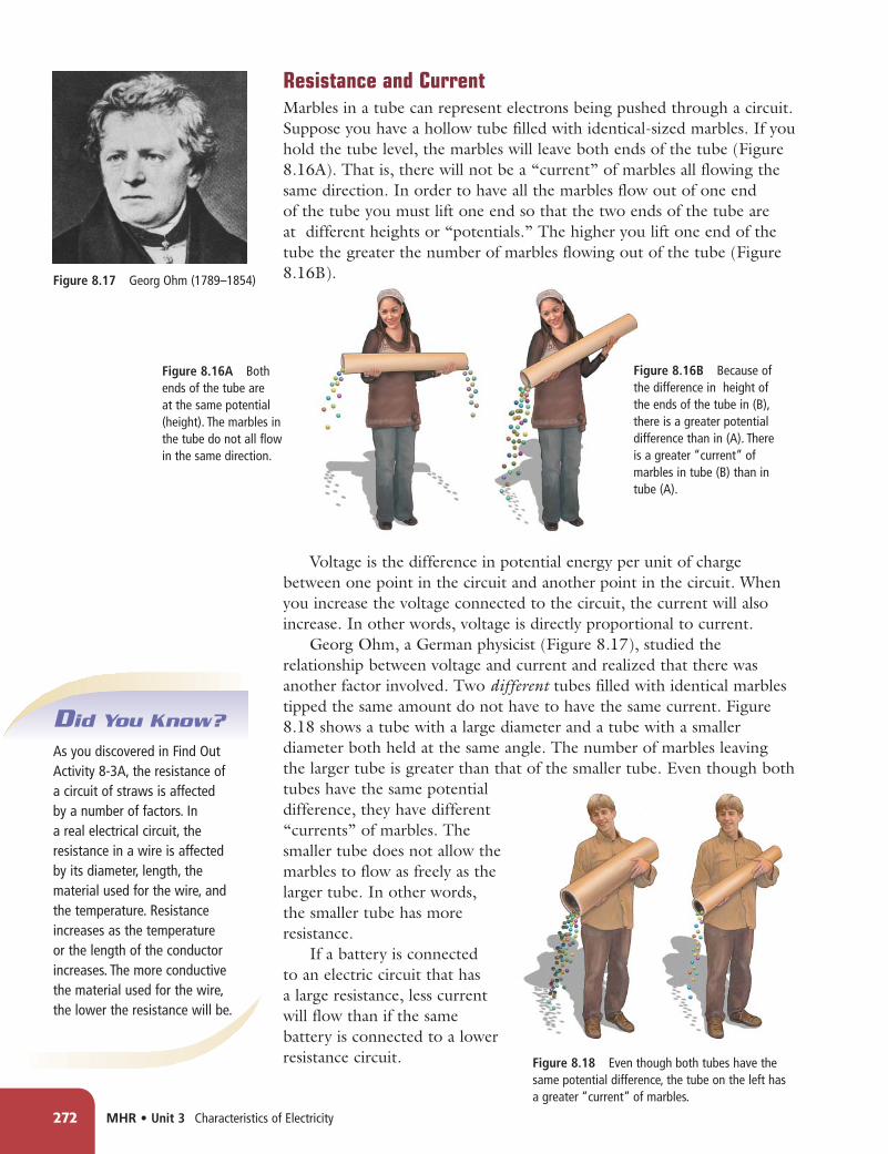
Figure 8.17 Georg Ohm (1789–1854)
Figure 8.16A Both ends of the tube are at the same potential (height). The marbles in the tube do not all flow in the same direction.
Resistance and CurrentMarbles in a tube can represent electrons being pushed through a circuit. Suppose you have a hollow tube filled with identical-sized marbles. If you hold the tube level, the marbles will leave both ends of the tube (Figure 8.16A). That is, there will not be a “current” of marbles all flowing the same direction. In order to have all the marbles flow out of one end of the tube you must lift one end so that the two ends of the tube are at different heights or “potentials.” The higher you lift one end of the tube the greater the number of marbles flowing out of the tube (Figure 8.16B).
Voltage is the difference in potential energy per unit of charge between one point in the circuit and another point in the circuit. When you increase the voltage connected to the circuit, the current will also increase. In other words, voltage is directly proportional to current.
Georg Ohm, a German physicist (Figure 8.17), studied the relationship between voltage and current and realized that there was another factor involved. Two different tubes filled with identical marbles tipped the same amount do not have to have the same current. Figure 8.18 shows a tube with a large diameter and a tube with a smaller diameter both held at the same angle. The number of marbles leaving the larger tube is greater than that of the smaller tube. Even though both tubes have the same potential difference, they have different “currents” of marbles. The smaller tube does not allow the marbles to flow as freely as the larger tube. In other words, the smaller tube has more resistance.
If a battery is connected to an electric circuit that has a large resistance, less current will flow than if the same battery is connected to a lower resistance circuit. Figure 8.18 Even though both tubes have the
same potential difference, the tube on the left has a greater “current” of marbles.
Figure 8.16B Because of the difference in height of the ends of the tube in (B), there is a greater potential difference than in (A). There is a greater “current” of marbles in tube (B) than in tube (A).
Did You Know?
As you discovered in Find Out Activity 8-3A, the resistance of a circuit of straws is affected by a number of factors. In a real electrical circuit, the resistance in a wire is affected by its diameter, length, the material used for the wire, and the temperature. Resistance increases as the temperature or the length of the conductor increases. The more conductive the material used for the wire, the lower the resistance will be.

Chapter 8 Ohm’s law describes the relationship of current, voltage, and resistance. • MHR 273
Word Connect
The symbol for the unit of the ohm is the Greek letter omega (�) instead of the first letter of ohm (O). This is because the (O) might be confused as the number zero. The symbol “I” for current stands for “intensity.”
Ohm’s LawBy measuring the amount of current that a given voltage produces, Ohm was able to calculate the circuit’s resistance. Electrical resistance is the ratio of the voltage to the current. The unit of measurement for electrical resistance is the ohm (�). The mathematical relationship comparing voltage (V ), current (I), and resistance (R) is called Ohm’s law and is written as:
R � V __ I
Ohm’s law is more commonly written in the form: V � IR
You can use Ohm’s law to calculate resistance.
Read the question:
What is the resistance of a flashlight bulb if there is a current of 0.75 A through the bulb when connected to a 3.0 V battery?
Use the formula:
R � V __ I
� 3.0 V ______ 0.75 A
� 4.0 �
State your answer:
The resistance of the flashlight bulb is 4.0 �.
Practice Problems
Try the following Ohm’s law problems. Show each step of your solution.
1. The current through a load in a circuit is 1.5 A. If the potential difference across the load is 12 V, what is the resistance of the load?
2. The resistance of a car headlight is 15 �. If there is a current of 0.80 A through the headlight, what is the voltage across the headlight?
3. A 60 V potential difference is measured across a load that has aresistance of 15 �. What is the current through this load?
Answers
1. 8.0 �2. 12 V3. 4.0 A
Converting Prefixes
Prefixes are used to indicate the magnitude of a value. milli (m) represents one-thousandth (example: 25 mA � 25 ____ 1000 A � 0.025 A)
kilo (k) represents one thousand (example: 5 k� � 5000 �)mega (M) represents one million (example: 12 MV � 12 000 000 V)
When solving a problem where some of the units contain prefixes, first convert the prefixes before you do your calculation.

274 MHR • Unit 3 Characteristics of Electricity
Determining the ResistanceThere are several methods you can use to determine the resistance.
Method 1: To experimentally measure the resistance of a device or load, the load must be connected to a source of potential difference, such as a battery. You can use a voltmeter to measure the voltage across the load and an ammeter to measure the current through the load. Then you can use Ohm’s law to calculate the resistance.
To obtain more accurate results, you can place several different voltages across the load. You then measure the current through the load for each voltage. Using Ohm’s law, you can calculate the load’s resistance for each set of data. These resistances can then be compared.
Method 2: In your classroom, you may have used a digital multimeter to take your voltage and current measurements. Most multimeters also have a setting for measuring resistance. An ohmmeter is a device that measures resistance. When a multimeter is used as an ohmmeter, the meter uses its internal battery to provide a voltage across the load. The meter measures the current leaving the battery and calculates the resistance. This calculated resistance is then shown on the display screen.
Read the question:
What is the voltage across a 12 k� load that allows a current of 6.0 mA?
Use the formula:
V � IR � (6.0 mA)(12 k�) � (0.0060 A)(12 000 �) � 72 V
State your answer:
The voltage across a 12 k� load is 72 V.
Practice Problems
Try the following Ohm’s law problems. Show each step of your solution. Remember to convert prefixes before calculating.
1. A 15 mA current flows through a 400 � lamp. What is the voltage across the lamp?
2. A 12 k� load is connected to a 90 V power supply. What is the current through the load in milliamperes (mA)?
3. A device draws a current of 1.2 mA when connected to 120 V. What is the resistance of this device? Give your answer in both ohms and kilo-ohms.
Answers1. 6.0 V2. 7.5 mA3. 100 000 �; 100 k�
Did You Know?
The current flowing in an MP3 player is very small, perhaps one-thousandth of an ampere. The current produced by a car’s battery to start the car is almost 100 A.

Chapter 8 Ohm’s law describes the relationship of current, voltage, and resistance. • MHR 275
Calculating Resistance8-3B
The resistance of a load can be determined by analyzing the relationship between the voltage across the load and the current. In this activity, you will use voltage and current data obtained from an experiment to calculate the resistance of the load.
What to Do1. A battery is connected to a load as shown. The
voltage across the device and the current through the device is measured.
A battery is connected to a load, and the voltage and current are measured.
2. Different batteries are connected to this same load and the following data is obtained. Copy this data table into your notebook. Give it a title.
3. Using Ohm’s law, calculate the resistance for each set of voltage-current data.
4. Calculate the average resistance of your five calculated resistances. To find the average, add the five resistances and divide the sum by 5. Record the average resistance. Include correct units.
What Did You Find Out?1. How did the resistances you calculated for the sets of
data compare? Were they exactly the same, close, or very different?
2. Given that the same load was used, explain why you think the values calculated might not be exactly the same for each set of data.
Think About It
Figure 8.19 Resistors are used to control current and voltage in electrical circuits.
The ResistorAny electrical component that has electrical resistance slows down current and transforms electrical energy into other forms of energy. A resistor is an electrical component that has a specific resistance. Resistors (Figure 8.19) can be used to control current or potential difference in a circuit to provide the correct voltage and current to the other components of the circuit. The circuit symbol for a resistor is shown below in Figure 8.20.
Voltage (V) Current (A) Resistance (�)
3.0 1.2
4.5 1.7
6.0 2.5
9.0 3.6
12.0 5.0
Figure 8.20 The circuit symbol for a resistor

Circuit Diagrams with Resistors8-3C
In this activity, you will draw circuit diagrams for circuits that contain resistors.
What to Do1. Draw the corresponding circuit diagrams for circuit A
and circuit B.
What Did You Find Out?1. Compare your circuit diagrams with those of a
classmate. List any similarities and differences.
2. Explain the advantage of the circuit diagram you drew as compared to the original illustration in this student book.
Think About It
276 MHR • Unit 3 Characteristics of Electricity
Resistance Is a Big LoserIt takes less effort to slide a heavy box across a smooth polished floor compared to pushing the same box across a rough floor (Figure 8.21). The rough floor provides resistance to the motion of the box. This resistance, or friction, of the rough floor produces much more heat than the smooth floor.
There is a similar effect when a battery tries to “push” electrons through a circuit. When the charge encounters resistance, some of the electrical energy stored in the electrons is transformed into other forms of energy, such as heat. When we say that energy is lost in a resistor, it really means that electrical energy has been transformed to other forms of energy. These other forms of energy do not easily get changed back into electrical energy.
Figure 8.21 Since the rough floor provides more resistance, more energy is transformed into heat by friction.
circuit A circuit B
The heat that is produced because of resistance in circuits can damage devices in the circuit, melt wires, and even cause fire. When designing circuits for complex electronic equipment, engineers build in safety measures to protect the equipment and the people using it. Find out more about the technological problems associated with resistance and how to solve them. Start your search at www.discoveringscience9.ca.

Chapter 8 Ohm’s law describes the relationship of current, voltage, and resistance. • MHR 277
Figure 8.22 The resistor in this illustration would have the first digit 1, the second digit 3, the power of 10 to the second power, and an accuracy within 5 percent. Therefore this resistor’s value would be 13 � 102 or 1300 � and is accurate within 5 percent.
Reading Check1. How does resistance affect current?2. What will happen to the current in a circuit if the voltage applied to
that circuit is increased?3. State Ohm’s law, which is the relationship of voltage (V ), current
(I), and resistance (R).4. What are the units of electrical resistance?5. What happens to the electrical energy when electrons flow through a
resistor?6. What does it mean when we say that energy is “lost” in a resistor?7. How do manufacturers of resistors indicate the value of the
resistance?
Decreasing the resistance allows more current with less energy lost to heat. Scientists have produced materials that have almost zero resistance. These materials are called superconductors. Find out how superconductors are produced and what applications they may have. Begin your research at www.discoveringscience9.ca.
Table 8.2 Colour Coding on Resistors
Colour Numeric Value
black 0
brown 1
red 2
orange 3
yellow 4
green 5
blue 6
violet 7
grey 8
white 9
Figure 8.22 displays the colour code of a resistor. The first band is the first digit of the resistance. The second band is the second digit of the resistance. The third band represents the multiplier or power of 10 factor of the resistance (the number of zeros that follow the second digit in the resistance value). If the resistor has a fourth band, it represents the percentage of accuracy between the indicated value and actual value (gold 5 percent, silver 10 percent, no colour 20 percent).
Resistor Colour CodeResistors are marked with coloured bands. These stripes are not for decoration but instead indicate the resistance of the resistor. Table 8.2 gives the numeric values associated with each colour.
first digit(brown)
second digit(orange)
multiplier(� 10 x)
(red)
accuracy (%)(gold)
Conduct an Investigation 8-3D on page 278
Suggested Activity

278 MHR • Unit 3 Characteristics of Electricity
Resistors and Ohm’s Law8-3D
SkillCheck
• Observing
• Measuring
• Controlling variables
• Evaluating information
In Part 1 of this activity, you will construct a circuit from a circuit diagram and measure voltage and current using a voltmeter and ammeter. In Part 2, you will calculate resistance.
QuestionHow do the calculated value and measured value of resistors compare?
Procedure
Part 1 Measuring Voltage and Current
1. Copy the following data table into your notebook. Give your table a title.
2. Using the resistor colour code, record the value of each of your resistors in your data table.
3. Construct the following circuit using one of your resistors and one 1.5 V cell. Be sure to leave the switch open until instructed by your teacher to close the switch.
Safety
• If any of the wires or resistors become hot, open the switch immediately.
• Make sure that the positive terminal of the ammeter is connected to the positive terminal of the battery. The negative terminal of the ammeter should be connected to the negative terminal of the battery.
• Never connect an ammeter directly across the terminals of a battery.
• There must be a load, in this case the resistor, in the circuit to limit the flow of electrons.
Materials• 2 different resistors
(100–300 �)• ammeter• voltmeter• conducting wires• four 1.5 V cells• switch
Construct this circuit in step 3.
Resistor Value Voltage Current Calculated Resistance (�) (V) (A) (�)
#1
#2
1.5 V

Chapter 8 Ohm’s Law describes the relationship of current, voltage, and resistance. • MHR 279
Conduct an INVESTIGATION
Inquiry Focus
4. Close the switch briefly and measure the voltage and current. Open the switch as soon as you have measured your values. Record these values in your data table. If your ammeter is measuring in milliamperes, be sure to convert this to amperes.
5. Replace your 1.5 V cell with two 1.5 V cells connected together. Make sure the cells are connected positive (�) to negative (�). When instructed by your teacher, repeat step 4.
6. Connect three 1.5 V cells together, again positive to negative. When instructed by your teacher, repeat step 4.
7. Connect four 1.5 V cells together, again positive to negative. When instructed by your teacher, repeat step 4.
8. Remove your first resistor and replace it with your second resistor. Repeat steps 4 to 7.
9. Clean up and put away the equipment you have used.
Part 2 Calculating Resistance
10. Using your measured voltage and current, calculate the resistance for each set of data. Record these values in the “Calculated Resistance” column of your data table.
Analyze1. Using the calculated resistances for resistor #1,
calculate the average resistance. Record this value. Include correct units.
2. Using the calculated resistances for resistor #2, calculate the average resistance. Record this value. Include correct units.
Conclude and Apply1. For each resistor, compare the average value of the
resistance to the value obtained from the colour code.
2. Give a possible reason for the calculated value and colour code value not being exactly the same.
3. As the current through an individual resistor is increased, what happens to the voltage across that same resistor?
Go to Science Skill 7 for information about how to use an ammeter and voltmeter.
Science Skills
Core Lab
280 MHR • Unit 3 Characteristics of Electricity
volta
ge (V
)
current (A)
0
2468
10
.10 .20 .30 .40 .50 .60
12vo
ltage
(V)
current (mA)
0
123456789
0.5 1.0 1.5 2.0 2.5 3.0 3.5 4.0 4.5 5.0
10
volta
ge (V
)
current (mA)
load #2
load #1
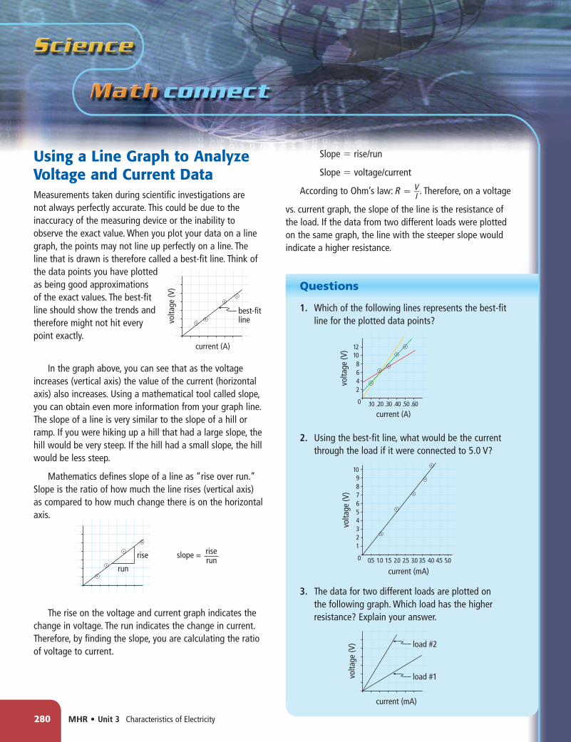
Using a Line Graph to Analyze Voltage and Current DataMeasurements taken during scientific investigations are not always perfectly accurate. This could be due to the inaccuracy of the measuring device or the inability to observe the exact value. When you plot your data on a line graph, the points may not line up perfectly on a line. The line that is drawn is therefore called a best-fit line. Think of the data points you have plotted as being good approximations of the exact values. The best-fit line should show the trends and therefore might not hit every point exactly.
In the graph above, you can see that as the voltage increases (vertical axis) the value of the current (horizontal axis) also increases. Using a mathematical tool called slope, you can obtain even more information from your graph line. The slope of a line is very similar to the slope of a hill or ramp. If you were hiking up a hill that had a large slope, the hill would be very steep. If the hill had a small slope, the hill would be less steep.
Mathematics defines slope of a line as “rise over run.” Slope is the ratio of how much the line rises (vertical axis) as compared to how much change there is on the horizontal axis.
The rise on the voltage and current graph indicates the change in voltage. The run indicates the change in current. Therefore, by finding the slope, you are calculating the ratio of voltage to current.
Slope � rise/run
Slope � voltage/current
According to Ohm’s law: R � V __ I . Therefore, on a voltage
vs. current graph, the slope of the line is the resistance of the load. If the data from two different loads were plotted on the same graph, the line with the steeper slope would indicate a higher resistance.
Questions
1. Which of the following lines represents the best-fit line for the plotted data points?
2. Using the best-fit line, what would be the current through the load if it were connected to 5.0 V?
3. The data for two different loads are plotted on the following graph. Which load has the higher resistance? Explain your answer.
volta
ge (V
)
current (A)
best-fitline
run run
rise rise slope =

Checking Concepts 1. What is the name of the property of a
material that slows down current and converts electrical energy into other forms of energy?
2. List the four factors that affect resistance in a wire.
3. Using Ohm’s law, state the relationship of current, resistance, and voltage.
4. What two values do you need in order to calculate resistance?
5. (a) What is the unit of resistance?(b) What is its symbol?
6. What is used to control current and potential difference in a circuit?
7. Explain how manufacturers indicate the value of resistance on each resistor.
8. Draw the symbol used to represent a resistor in a circuit diagram.
Understanding Key Ideas 9. A 1.2 A current flows through a 250 �
resistor. Calculate the voltage across this resistor.
10. A 120 � resistor is connected to a 12 V battery. Calculate the current through the resistor.
11. An unknown resistor transforms 2.0 mA of current when connected to a 9.0 V battery. Calculate the value of this resistor.
12. A classmate hands you a resistor that has the following colour bands: yellow, orange, red, and silver. What is the resistance of this resistor?
13. a) Using the data below, construct a graph of voltage vs. current, and draw a best-fitline.
b) Determine the slope of the best-fit line. c) What does the slope of the graph
represent? 14. A light bulb is connected to a battery and the
brightness of the light is observed. A resistor is then connected between the battery and the light bulb and the brightness of the light decreases. Explain this observation using what you know about energy and circuit components.
15. Draw a circuit diagram for the following circuit.
Chapter 8 Ohm’s law describes the relationship of current, voltage, and resistance. • MHR 281
Suppose you are given several batteries, an ammeter, voltmeter, connecting wires, and a resistor that has no coloured bands indicating its value. How could you determine an accurate value for this resistor?
Pause and Reflect
1.0
1.5
2.0
2.5
3.0
3.5
4.0
0.21
0.44
0.58
0.82
0.98
1.15
1.32
Voltage (V) Current (mA)
The Effect on Changing Voltage on the Current in an
Electrical Circuit

282 MHR • Unit 3 Characteristics of Electricity
Prepare Your Own SummaryIn this chapter, you investigated the relationship between current, voltage, and resistance. Create your own summary of the key ideas from this chapter. You may include graphic organizers or illustrations with your notes. (See Science Skill 8 for help with using graphic organizers.) Use the following headings to organize your notes:1. Electrical Energy2. Current3. Voltage4. Resistance and Ohm’s Law5. Circuits
Checking Concepts 1. What is the purpose of a battery? 2. In a battery, what form of energy is
converted into electric potential energy? 3. What is the relationship of electric potential
energy, charge, and potential difference (voltage)?
4. What provides the electrical potential in a circuit?
5. When electrical potential is used, what happens to voltage (potential energy)?
6. What materials are needed to produce an electrochemical cell?
7. List five methods of producing electric energy.
8. What unit is used for measuring voltage? 9. What is the purpose of a voltmeter? 10. What is the purpose of an ammeter? 11. Copy and complete the following table in
your notebook.
12. Draw the following circuit symbols. (a) battery (b) bulb (c) resistor (d) voltmeter (e) ammeter (f) switch 13. What is the relationship between amperes (A)
and milliamperes (mA)? 14. What are the four basic components of an
electric circuit? 15. Explain the relationship between resistance
and resistor. 16. State the relationship of voltage (V ), current
(I), and resistance (R). 17. Describe and explain the relationship
between resistance and (a) the length of a wire. (b) the diameter of a wire. 18. When an electron passes through a resistor,
what happens to its electric energy? 19. What is the purpose of an ohmmeter? 20. Resistors have a maximum of four coloured
bands stamped on their surface. What does each band represent?
C h a p t e r
8
Voltage V
Current amperes
Resistance �
Symbol Unit Unit Symbol

Chapter 8 Ohm’s Law describes the relationship of current, voltage, and resistance. • MHR 283
Understanding Key Ideas 21. In order for skiers to have potential energy,
they must travel to the top of the hill. Explain how this is similar to electrons in an electrochemical cell.
22. A voltmeter is connected to the (�) and (�) terminals of a battery and measures 6.0 V. If the lead on the (�) terminal is removed and now touches the (�) terminal, what would now be the reading on the meter? Explain your answer.
23. Explain how two 9.0 V batteries could have different amounts of electric potential energy.
24. Explain the difference between static electricity and current electricity.
25. By looking at an electrical set-up, explain how you would determine if it is a complete circuit.
26. You enter a dark room and press the light switch on the wall. The ceiling light turns on immediately. Explain why you do not have to wait for the electrons at the switch to travel to the ceiling light before the light goes on.
27. Draw a circuit diagram for the circuit below.
28. Convert each of the following: (a) 400 mA � ______ A (b) 18 k� � ______ � (c) 12 MV � ______ V 29. The current through a 120 � resistor is 2.0
A. Calculate the voltage across this resistor. 30. The current through a load is 75 mA. If the
potential difference across the load is 12 V, what is the resistance of the load?
31. Calculate the resistance of the bulb in the following circuit:
32. A fellow student hands you a resistor and the bands of colour are brown, black, and orange. What is the resistance of this resistor?
33. Draw a circuit diagram for the circuit shown below.
A common flashlight contains a battery, a light bulb, and a switch. Draw a possible circuit diagram for the flashlight. In your circuit diagram, does it matter where the switch is located? Explain your answer.
Pause and Reflect
12V
3.0A