nl,5-93-017 n u am no o cf
TRANSCRIPT

Plant Mod. N: 93 OWNL,5-93-017 n u am no o
.
CfA TT. 9.1 2. (34- PP) pg ..,'*
REVISION 2 10CFR50.59 PROGRAM MANUAL'
A'ITACHMENT ACP&L SAFETY REVIEW PACKAGE Page 1.,of.34
SAFETY REVIEW COVER SIIEET
DOCUMENT NO. PM 914)38 REV.NO. O
DESCRIPTION OF TITLE; SIfiMLLfM}LD_ETECTION SYSTEM UPGRADE FOR HPCL RCIC.RWCU AND RHR
1. Assigned Responsibilities
Safety Analysis Preparer: Tom ickemeyerLead ist Safety Reviewer: Tom ickemeyer
:.;d Safety Reviewer: Civde Fletcher
2. Safety Analysis Preparer: Comp ete PART I, SAFL'TY ANALYSIS
Safety Analysis Preparer / M T- 14-it.'DATE/ SIGNATURE f
3. Lead 1st Safety Reviewer: Complete Part II, Item Classification.
4. Lead 1st Safety Reviewer: Part III may be completed. If either question 1 or 2 is "yes,"then Part IV is not required.
5. Lead 1st Safety Reviewer; Determine which DISCIPLINES are required for review of this item(including own) and mark the appropriate block (s) below.
DISCIPLINES Reauired fPrint Name) Sicnature/Date (Sten 7)
[ ] Nuclear Plant Operations[ ] Nuclear Engineering .
d u/9s N '.|X] Mechanical M u 5.Lun a t ri& Stdu.&[X] Electrical her J. r6 a.es a4 Sah J/8#
Tom Hokemeyer / M ( % e s T/2d1 Jt[X] Instrumentation & Control-
[X] Structural Leo CamobeliMWauld*Mb/dsL6/nJfsuL ,, f.s/wU /
[ ] Metallurgy[ ] Chemistry / Radiochemistry[ ] Health Physics[ ] Administrative Controls 1
6. A QUALIFIED SAFETY REVIEWER will be assigned for each DISCIPLINE marked insten 5 and his/her name printed in the space provided. Each person listed shall perform aSAIETY REVIEW and provide input into the Safety Review Package.
7. The Lead 1st Safety l eviewer will assure that a Part III or Part IV is completed (see step 4above) and a Part VI .f required (see 9.b of Part 10. Each person listed in step 5 shall signand date next to hisiner name in step 5 indicating completion of a SAFETY REVIEW.
8, 2nd Safety Reviewer: Perform a SAFETY REVIEW in accordance with Section 8.0.
2nd Safety Reviewer C db - Date i
DISCIPLINE: Instrument 1 tion & Control / /Xti M2
9. PNSC review required? If "yes" attach Part V and mark reason [X] []below:
[ ] Potential UNREVIEWED SAFETY QUESTIONN Question 9 of Part IV answered "Yes"[ ] Other (specify):
0 AI-109 Rev. 0019302030155 930125PDR ADOCK 05000324P PDR

Plant Mod. No 4 OM'
Oneid Rev. N:
REVISION 2 10CFR50.59 PROGRAM L.ANUALATTACHMENT A
CP&L SAFETY REVIEW PACKAGE Page __2., of 34
PARTI: SAFETY ANALYSIS(See imtructiorts in Section 8.4.1)
(Attach additional sheets as necessary)
DOCUMENT NO. PM 01038 REV. nom 0
DESCRIPTION OF CIIANGE:
DLntgwe functions of the Steam Leak Detection (SLD) system comeonents addresud by this plantmodification m:lud;.1
o To monitor ambient tempentures in the following locations:
o Along the HPCI steam supply piping outboard of the Drywell,o In the HPCI Turbtne room,o Along the RCIC steam supply piping outboard of the Drywell,o Near the RC!C Turbine,
in the general Reactor Building area containing the RWCU Inlet, Return and Reject piping outside ofothe RWCU rooms.
o Inside the RWCU Pump Room., and IIcat Exchanger Roomo inside the Main Steam Tunnelo Near the RHR Emergency Area Coclers
o To monitor the vent air inlet / outlet differential temperature in the following locations:
o HPCIIRCIC nuni . team tunnel,o HPCI Equipment Area,o RCIC Equipment Area,o RWCU Pump Rooms and Heat Exchanger Room,o Main Steam Tunnel.o RHR Areas
o To monitor the differential flow between the RWCU system inlet and the two system outlet paths.
To provide alarms when any of the temperatures or the differential flow exceeds designated setpoints,o
To initiate closure of the following PCIS valve groups when the associated temperature / differentialo
temperature or the RWCU differmtial flow exceeds established setooints and any delay times. Isolationinitiatica response times must _ .. the 13 second assumptions utilized for the Reactor BuildingEnvironmental Report.
o HPCI - Group 4o RCIC - Group 5o RWCU - Group 3
The Main Steatu and RHR channels associated with the H12-P614 panel are for alarm and indication only.
To provide control room indication for the temperature locations monitored. Limited indication capabilityois provided at parel H12 P614. Only one ambient and one differential thermocouple channel temperatureat a time may be displayed on the currect Riley system. 'nte Fenwal switch channels provide no indicationcapability,
To provide control roorn tndication for the RWCU inkt, reject and differential tTow (No return fMwoindication currently is provided).
O Al-109 Rev. 001
)|

Plent Mod. Nr 'TI- 0 38 -F1:ld R:v. Nr o.,
C'IREVISION 2 10CFR50.59 PROGRAM MANUAL Pogo NaATTACHMENT A
CP&L SAFETY REVIEW PACKAGE Page ) of 34
PART I: SAFETY ANALYSIS (cont'd)
' DOCUMENT NO. PM 91-038 _REV.NO. O_
DESCRil' TION OF CllANGE (cont'd):
To provide input to ERFIS and the Process Compute. for selected tempersture and flow channels.o
Eti< tine Hardwafr
: The current hardware configuration utilized to perform the temperature sensing portion of above funcuonconsist: of a combination cf local Fenwal temperature switches, local thermocouples connected to Rileytnp smtches in the control room and supporting reky logic. Most of the control room components arelocated on and in H12-P614.
The hardware currently utilized to perform the RWCU flow sensing portion of above function consists ofo
Rosemont, GEM AC and Agastat devices. The CEMAC and Agastat analyticalinstruments and time delayrelays are located in the H12 Pbl1 and H12-P613 control room panels. The inlet and reject flows aredisplayed on H12 P603 and the differenti I flow is displayed on H12-P613.
PmNems With Exictine Conficuration:
1, The existieg SLD system configuration has been a chronic source of problems, resulting in many LERs.
2. Some of the rnore significant problems with the temperature-based portion of tbt LDS involve the Rileyand Fenwal hardware and include:
2.1 Spurious system isolations can be initiated by Riley switches during AC power restoration.
The susceptibility of these switches to spurious trips has been documented by GE SIL No. 416and IE Information Notice 8649. As noted in the SIL, whencier one of the switches is re-powered, a momentary signal f-em the Riley may result in a ' relay race' within the associatedsystem and the involved uip func: ion may eccur.
2.2 Spunous system isolations can be initiated by Riley switches due to momentary breaks in the inputthermocouple continuity.
Thermocouple burmut, or own circuit, rarely occurs at either the ther.nocouple element or at thetermination of the extension cable to the thermocouple. The problem at BNP has ietated more toopen circuits occurring within the control raora panel H12-P614 due to intermittent evnnectionscaused either by vibration or by handling of wire bundles.
Two primary causes for the frequency of these open circuits are:
2.2.1 The congested wiring configuration at the Riley switch termtnals makes it difneult toperform and verify terminatiot. of the thermocouple input wires. Many of the thennoccuplelead wires are un-lugged and are fastened directly under the termmd screws, in accordancewith Riley recommendation
2.2.2 The impact of the above condition is compounded since the thermocouple leads at each ofthe Tech Spec-related Rileys must be lifted and then reterminated monthly to permit inputsignal substitution during the MSTs.
O AI 109 Rev. 001

_ _ _ _ _ _ _ - __ _ -_ . _ _ _ _ _
Plant Mod.16 * * 112 l
th14 flov. No F,
REVis!ON : 10CFR50.59 PROGRAM MANUAL E"9' U" i
A*ITACllMENT ACP&L SAFETY REVIEW PACKAGE Page _4_ of _ M
;
PART1: SATCTY ANALYSIS (cont'd)i
DOCUMENT NO. _biRi P18 REY.NO. Oc
4DESCRil'FION OF CllANGE (cont'd):
Further uncertainty has been introJuced by the facts that only certain Riley models includethe burnout trip feature and that we do not control where modides with that burnout tripfeature are installed. Either is permitted.
2.3 Maintenance and modification activities are difficult in lil2 P614. Personnel safety is jeopardizedwhen it is necessary to reach deep into the cabmet among adjacent hot circuits. Inadvertent plantimpact is always posuble and spurious system isolations have frequently occurre/ during theseactivities.
The Riley hardaare and the associated relay, switches and timers are poorly arranged. ne vendor .mierconnection drawmgs are iusccurate and panially illegible. The lack of wire tags on the vendor
"
mterconnect w1nny and the congested w1re bundling makes it nearly impossible to visually tracewinns from pomt to point withoat extensive clearsaces and wire bundle separation.
2.4 Personnel safety concerns have been documented relative to the hazardous nature of the frequent andextensive climbmg required to perform MSTs on 'he 15 Fenwat switche4 located in the !!PCI, RCICand mtm steam tunnel areas.
Monthly MSTs require local access to apply heat to each of the fifteen switches as part of the channelfunctional tests. Quarterly MSTs require removal and reinstallation of the eight IIPCI switches inarder to perform the shop calibrations included in the channel calibrations. Refuel MSTs require thesame for the seven RCIC switches.
In contrast, heat application for channel functioned testing of the thermocouple-based steam leakdetection channels is only required at quamily re refuel intervals. He thermocouples are inherentlystable, passive devices, while the 1%sts are adive components. Even though a case might be madefor wme increase in the surullana interval for the Fenwals, it is unlikely that it could ever belengthened to nearly that of the thermocouples.
0.5 The seveillance testing frequency required for the Riley based instrumentation is too short.,
The nature and frequency of the MST: were establ4hed barad on the characteristics of the Rileyhardware and appear to be essentially appropriate. The Riley equipment is less accurete and drift-resistant than more modem equipment such as the !iUMAC. It also does not provide the eatensiveSelf test featutes available in the NUMAC. It is unlikely that an extention of the Riley surveillance
.
mtervals to anywhere near those hoped for with the NUMAC system could ever be justiced.
0.6 Spare and replacement Riley parts availability is becoraing a problem.
The product line is becomie3 obsolese. The vendor continues to support with repairs and specialproduction runs, but cost and lead times are increasing. .
O Al lO9 Rev. 001
- _ - _ -

.
__ _-. _ . - _ _ .
rtid Rev. Ma o i, ,
REYlSION 2 10CFR50.59 PROGRAM MANUAL Page Nr ct ;
A'ITACHMENT A !'
CP&L SAFETY REVIEW PACKAGE - Page i.of 34
- PART !! SAFLTY ANALYSIS (cont'd):
DOCUMENT NO. PM 91-038 .REV,NO. O i
e
DESCRIITION OF CilANGE (cont'd): |
3. Some of the more significant problems anociated with the RWCU Differential Flow based portion of the !'
LDS system involve the GEMAC hardware and include: ;
3.1 Spurious RWCU system isolations can be initiated by the differential fl6w loop, for reasons that $'
include:
I3.1.1 Routine upscale rudings caused by the lack of density compensation reduce the effective
marl;in between the normally indicated differential flow reading and the idolation setpoint.His increuct the vulnerability for inps due to normal system operational transients. !
~
3.1.2 Apparent ddticulty in keeping the instrument sensing lines full between the flow orifice tapsand the differential flow transmitters. His would offr.et the differential pressure sensed bythe transnutter by a value equivalent to the lost head, ne reject line flow orifice is -especially susceptible to this problem because it is occasionally subject to partial condenservtcuum. ,
his plant modification addresses the 3.3.1.1 root c.use in that it will result in a ,
'
configuration where, in the absence of a real leak, the normalized differential' reading will beapproximately zero. De routine espected indicated differentist will then be approximately
'
43 OPM below the 43 OPM actpoint and thereby allow full ase of that margin, along withthe proposed extended time delay of 30 minutes, to minimize trips due to routine operational- t
transients,
nis project does not provide a fix for the 3.3.1.2 root cause, ne electronic portion of the i
differential loop instrumentation is included in this project due to the capability of the.~ '
NUMAC to remedy the density compensation poblem.
3.1.3 Downscale indications on the differential flow indicator 031 FDI R615. NCR A 89 052documented this sa a potantial Mode 3 operability issue. : ha the inlet flow temperaturestarts to decreast below normal opeinting temperatures, the water density increaans and the ,
volumetrie flow rate decreases, nis creates a situation where the inlet volumetric flow ratecould drop below the sum of the return and reject volumetric flow ratesr The 031 FDI-R615 differential flow indicator would then urive downscale and a leak greater than the 43OPM serpoint could potentially exist without actuating the system isolation trip units.
This condition is caused by the absence of density compensation provisions in the flow -instrumentation. !
With the NUMAC system, negative differential flow readings will not be displayed. : Each of -the three input flow channels will be monitored for 'out of bounds' signal levels. No.'
valuation of downscale differential values, such u is now permitted by Special Proceduree
86 090, will be necessary.
Based on the loop tolerance ultimately established for the NUMAC instrumentation, the L'
required margin between the setpoint and the Tech Spec Limit of 53 GPM might be reduced,
j= and it might then be possible to raise the setpoint (not currently planned within the scope of 3
|; this project). ,
L ,.*
. O Al 109 Rev 001
~ . - . - - - - = .. ==- ..- - ., - .- -.- - - .- - . .

._. - _ _ - _ _ _ _ _ _ _ _ _ _ _ _ _ _ .
Nnt Mod. Nm 9 t s inrDeld R:v. N> o
REVISION 2 10CFR50 59 PROGRAM MANUAL P"7' N N ' 'A'ITACHMENT A
CP&L SAFETY REVIEW PACKAGE Page 1 of 34
PARTI: SAFITY ANALYSIS (cont'd)
DOCUMENT NO, PM 91-038 REV.NO. 0 ,
DESCRil"flON Ol' CIIANGE (cont'd):
3.1.4 Inabihty to logically compare the flow values displayed on tbc RWCU inlet, reject ard ,
'ifferential flow indicators..
Due to the lack of density compensation, the flow rates displayed for theAe three parametersare in volumetne umts, rather than mass units, and therciore cannot te meaningfullycompared to each other,
3.1.5 There is no way to determtne the RWCU retuni Dow rate.
No indicator exists for RWCU return flow, it was not part of GE's design.
3,1.6 The differential flow instrumentation is not redundant. When it is found to be inoperable,Tech Specs require either that it te restored operable within two hours or that RWCU bepolaird.
Non redundant design was nortral for GE plants of our vintage, however, and there is noregulatory requirement or operationalincentive to add redundancy at this time.
Chances To De implemented By This Plant Modifiention: The following system conGruration changes will bea:comphshed:
1. Replace all of the Riley hardware and most of the associated components in lil2 P614 with four GENUMAC microprocessor units.
2. Replace the fifteen llPCI and RCIC Tenwal switchen with thermocouples. Connect these newthertrwouples to NUM AC monitoring / trip channels.
3. Remove the OEM AC and Agastat components used for RWCU differential flow monitoring. 'Ihe existingnow transmitters will be connected to one of the above four NUMAC chassis. Connect RWCU processtemperature thernvcouple signals from each of the three flow paths to the NUMAC system for use indensity correction.
4 The now and differential now indications will be improved as follows:
0 Move the RWCU differential flow indicator from H12 P613 to lil2 P603.o Add RWCU return flow indication to H12 P603,
Temperature compensated volumetric flow rates for the inlet, return and reject flow channels will beodisplayed on the NUMAC screen in H12 P614. In addition, the adjusted flow rates ' normalized' to acommon temperature of $33*F for each of those flow paths will be displayed both on the N_UMACscreen and on vertical indicators on H12 P603. Differential flow will be displayed in normalized spmon both lil2 P614 and on H12 P603.
5. Decrease the range of the RWCU reject flow loop fmm 250 rpm to 125 gpm @ 130'F (150 gpmnormalized to 533*F).
6. Replace the existing separately wired individual ERFIS input signals with multiplexed inputs transmitted onfiber optic cables.
O Al 109 Rev. 001
. ~ ~ . . , .
'Pl::t Mod No Sl*C.!LPle.id Rev, No J2 -
Page Ho MREVISION 2 10CFR50.59 PROGRAM MANUAL
'
ATTACHMENT ACP&L S AFETY REVIEW PACKAGE Page 2. of _ 34
PART h SATITY ANAISSIS (cont'd)
DOCUMENT NO. P.11.Al;038 REY.NO. O
DESCRIPTION OF CilANGC (cont'd)::
Elimmate the steel bamers and internal panel conduits that provide intr <livision sep.vntion between the-
IIPCI and the RCIC leak detection wmponents and circuits.
6. Repla:e the 125 VDC power supply that currently supplies the RCIC isolation channel instruments with120 VAC Emergency power, thereby eliminatmg the TOPAZ inverters.
9. Subnut a Tech $pec ch nge to:
o Delete the channel check surveillance test for the RWCU a Flow . liigh holation function,
o Extend and standardire the channel functional test and channel test surveillance frequencies for theRWCU e Flow . High, llPCl Ambient and a Tempersture, RCIC Ambient and a temperature, andRWCU Ambient and a Temperature isolation functions,
;o In:rease the RWCU a Flow isolation time delay from 45 seconds to 30 minutes.
o In:rease the RWCU a Flow Allowable Limit /Setpoint from $3 to 73 gpm.
Delete the instrument response time teatmg requirements for the following isolation functionsto
o llPCI steam line tunnel Temperature high,RWCU Area Temperature . l{igh and RWCU Area Ventilation a Temperature . liigh,o
o RWCU a Flow Iligh.
10. Revise the power source for the three RWCU flow transmittert Delete the esisting connections to theGEM AC power supply in lil2 P613 and rewire the transmitters to obtain power directly from the B21XY 5949B NUM AC chassis.
ANALYSIS:
The hardware, software and Techmcal Specification changes described above will provide a significant upgradeof the steam leak detection instrumentation. Improvements will be achieved in the areas of reliability,accuracy, data presentation, surveillance testing, problem diagnosis, repair and system availability.
A discussion of the safety implications of each of the changes desenbed above follows:
1. Replacement of the Riley hardware and most of the asaciated components in II12 P614 with fourGE NUMAC microprocessor units.
The existing Riley thermocouple monitor units and accessories are original plant equipment that isnearly obwlete. Replacement units and repair parts are difficult to obtain. Surveillanr4 testing andmaintenance activitica inside the II!2-P614 cabinet are difficult due to the poor physical arrangementof the components and internal wiring and due to the poor accuracy of the vendor drawings thatdescribe that configuration. Numerous spurious isolations have occurred due to factors such as -electncal noise, momentary circuit interruptions caused by poorly terminated power and signal cables,and inappropriate wire lifts based on the vendor drawings.
O Al 109 Rev. 001
- - . . - . . . .

~c
Plcmt Mod. Ni 4 ' * 0 3 Bheld R:v. Nm o ;
.,
REVlil0N 2 10CTR$0,59 PROGRAM MANUAL P898 NO J |ATTACliMENT A
CP&L SAFETY REVIEW PACKAOT Page J,,,of' N |t
PART1: SAIITY ANALYSIS (cont'd!
DOC 1' MENT NO. PM 01.n3tt _REV.NO. 0._
.
AN ALYSIS (cont'd):
The replacement NUMAC system will clinunate or reduce the occunence of problems due to all of'
the above causes. ,
r
ne system has been desiped and nanufactured under GE*a nucleat QA program. NUMAC softwareis developed, tested and controlled io accordance with GE's V&V program. He system has beenseismically quahned by OE to a genene response spectra. OE has designed and analyred the BNPmounting con 6ruration (in panel H12 P614) to assure that the seismic spectra at the installed location ,
will be within that to which the system is qualified. The NED civil group has reviewed summarydocumentation of the OE analysis to confirm the applicability of the GE documentation to BNP (ref:NED Calculation OE41-0033). .
Accurate and legible General Electnc drawings w,ll be issued into the BNP vendor drawing system todesenbe the NUM AC equipment and the physical arrangement within the lil2 P614 cabinet. Many of .
*
the anociated CP&L cabmet physical and winng drawings have been redrawti within the scope of thisproject in order to improve the legibility and accuracy beyond that of the entsting ones. ,
ne NUMAC system is designed to resist influence by etternal EMI interference.,
ne self test features of NUM AC us!! provide for prompt identification of failures in either inputcircuits or in internal components or software, ne resultant self diagnosis error messages will-facilitate performance of cortective maintenance.
With the NUMAC mcde keylock switch in the OPER(ate) position, any manipulation of the NUMACfront panel keys has no impact ou the actup or operation of the system. La order to initists calibration ' -E
activities, the keylock switch tnust be turned to the INOP position. Access to the chauis and channelsetup options are fucher restikted by the need for a panword.
'
De functional performance of the NUMAC based system will eaceed that of the Riley based systemthat it will replace.
2. Replacement of the fifteen IIPCI and RCIC Fenwal switches with thermoccupies that will connect toNUM AC inonitoring/ trip channels.
This change will helpjustify the elimination of the monthly surveillance te4 ting requirementsanociated with the Fenwal switches, he thermocouples that will be installed in their place areconsidered to be paasive devices and are not subject to routine surveillance testing. Based on thecurrent requirements for the other steam 1-ak detection thermocouple based channels governed by thesame Technical Specification, the recommended surveillance will be limited to a refuel frequency
'
verification of an appropriate channel response (upscale or downscale deflection) when the'
thermocouples are either heated or cooled as part of the channel calibration MST.
'
This change will provide Operations with display capability (on the NUMAC screen) for these 15previously blind chann:Is, thereby improving the range of detail information available for use inidentification, mitigation and post isolation tuonitoring of systern leaks. .
Removal of thew 15 locally mounted Fenwat switches will resolve a long standing personnel andequipment safety hazard succiated with the frequency and difficulty of the climbing necessary for ,
those tests.
.
O Al 109 Rev. 001
- . ._- __ _ _ ,_ . _ . _ . _ __ - _ -

I'
Plcset Mod Na 'Yro038Mald 16. Na 0*
.
ItEVlilON : 10CFR50.50 PROORAh! h1 ANUAL Page Nm 0 3 :
A'ITACllhtENT ACP&L $ ArlTY REVIEW PACKAGE Page 2 of l L.
PART1: SAETY ANALYSIS (cont'd) -
DOCO1ENT NO. fM 91-0M REY. NO.-- 0,
ANALYSIS front'dh
Mounttng brackets for the replacement thermacouples have ben seismically designed and analyzed(ref: NED Calculation OE410030 91038).
The functional performance of these new thermocouple channels will exceed that of the local switchesthat they will replace.
3. Removal of the Gl:MAC and Agastat components med for RWCU differential flow monitoring.Recon 0guration of the delta flow loop by connatJon of the taisting 00w transmitters to the 1121 XY.894911 NUMAC t. hauls and connection of RWCU procas ternperature thermocouple Signals fromeach of the three now paths to the NUMAC systern for use in demity correction.
The existing differential flow function compares the magustude of a single RWCU inlet flow channelto the sum of the two effluent now channels. Any difference is interpreted as leakage, ne existinginstrumentation in exh of the flow channels consists of an onfice plate pnmary element, a differentialpressure transnutter arid a square root convertet. Each of the three channels provides an input to arummer which develops a cunent output proportional to the flow difference. A differential indicatorand four separate inp units are driven by that current output. Two of the inp units are used to initiate111 and 111111 control room annunciators. The third and fourth trip units stari 45 second delay timersfor closure of the Div 1 and Div !! containment h,olation valvea. respectively. Although the inlet andreturn How channels are subject to significant temperature variation dudng the Modes 1. 2 and 3 inwhich this function is required to be operable, the computed now rates are not density compensated,
ne NUM AC system will continue to utilize flow onfice plates and differential pressure transmittersfor the input flow signals. He NUM AC based systern will provide the following advantages over theexisting anangement:
1) The three square root converters, one summer, four trip units and two delay timers will beclinunated by this modification, ne NUMAC processor will perform the equivalent functionsmore rehably, with less drift and improved accuracy.
) Density compensation will be provided utiliz.ing signals from three existing RWCU processtherrnoccuples The NUMAC programming includes default logic that will assure a continuousconservative calculation for differential flow in the event that any or all of the densitycompensation mput thermocouples wers to fail.
3) All three of the involved flow orifice plates will be replaced per this modification. The rejectflow orifice has been resired to accommodate a reduced full range flow rate (further discussiou innext section). He inlet and retum flow onfice plates will be replaced with new ones of the samedesign and bore size as the existmg ones. His action will eliminate any loop uncertainty.attributable to wear on these plates over their current installed lifetime.
4) Self-testing of the NUMAC will be performed on a continuous cycle while the NUMAC is in the ;OPERATE mode.
,
|
|
0 Abl09 Rev. 001
. - - - ,. .. . - - -_- . --. .

_ _ _ _ _ _ . _ _ _ _ _ _ _ _
Nat Mod. Na 'f' - 0 3 9rkki nant, N O.,
REY!$10N 2 10CTR50.59 PROGRAM M ANUAL Pcrge No Cl +ATTACl! MENT A
CP&L SAFETY REVIEW PACKAGE' Page ,,EL hf ).L,
PART 1: SATETY ANALYSIS (cont'd)
DOCUMENT NO. PM 01-03: REY. NO. O
ANALYSIS (cont'dh
5) The NUM AC RWCU a Flow screen will display the following parameurs:
o Flow transmitter signal for each channel (MADC),o Onnce plate dp for each channel ('we proportional to MADC signal),o Flow temperature of each channel (*F) for use in density compensation,o Calculated compensated flow rate for each channel (in equivalent gpm at the respective
channel design temperaturea),o Calculated normalized flow rate for each channel (in common units of gpm at the syste n
design temperature of 533'F),o Calculated differential flow (in common units of gpm at the system design temperature of
$33'F).
Availability of tius depth of data w111 provide additional information useful for evaluating thelocation and/or validity of any tndicated increase in differential flow.
The functional performance of the NUM AC based differential flow loop will eaceed that of theGEMAC based loop that it will replace.
J. Improvernent of the RWCU flow and differential flow indicatiors as follows:
o Mottinent of the RWCU differential flow indicator from Ill2 P613 to Ill2 P603.
The caisting differential flow indicator 031.FDI R615 is located on the Ill2 P613 bacic panel and isinconvenient for use in prevention, or management of the reset, of potential 111 and H1411 control -room alarms and isolation tirner cycles. Per this modification, this indicator will be moved onto thelil2 P603 control room panel. Availability at this new location, adjacent to the RWCU pump andvalve controls, willimprove the usefulness of this instrument for use by operations to avoid spuriousGroup 3 isolations during system transienta such as fill, startup and shutdowti,
Installation of this instrument in lil2-P603 has been seismically designed and analyzed (ref: NEDCalculation OE410030-91038).
o Addition of RWCU return flow indication to lil2 P603.
The caisting return flow channel providea no indication. Per this modification. the return flowratevalue will be displayed both on the NUMAC screen and on the new 031 F15954 vertical indicatorthat will added to the II!2-P603 panel.
Since the flow channels will be normalized to a common urtits basis, the system return flow shouldequal the system inlet flow, as displayed on G31 F1 R609, during normal RWCU systern operationwhere the full system flow is returned to the reactor. Availability of this flow rate value will provideadditional information useful for evaluating the location and/or validity of any indicated increase indifferential flow.
Installation of this instrument in H12 P603 has been seismically designed and analyzed (ref: NEDCalculation OE410030-91038).
!,
!
i-
0 Al 100 Rev. 001
i.-.

Plant Mod. Ns 41 * O M '
Flaid R:v. No O,
REYl510N 2 10CFR50.!? PROGRAM MANUAL Pcne No M ;
ATTACllMENT A- '
CP&L SAFETY REVIEW PACKAGE Page._1L of M
PART1: SAFETY ANALYSIS (cont'd)
DOCUMENT NO. PM 91-0M REY. NO. O
ANALYSIS (cont'd):
Addition of capability to dhplay itsnperature comperaated solumetric flow ratts for the inlet,oreturn and reject flow channels on the NUMAC screen in lil2 N14 and to dhplay the adjustednow rates "normalind" to a common itsnperature of $33'r for each of those flow paths on boththe NUStAC screen and on vertical Indicators on lil2 N03. Differential flow will be displa)ed -
in normallied gpm on both lil2 W14 and on Ill2.N03.
NUM AC will *normalin' the Dow rates for each of the three flow channels to a common units basisof grm at 533*F. This will permit direct comparison of the readings on the various flow channelswithout first having to manually calculate the density differences characteristic of the different flowonfice design temperatures. Normalisation permits direct comparison to the Tech Spec AllowableValue now rate which is itself based on the system design temperature of $33'F. These hermalizednow rates will also be utiliud for the RTGB display indicatorn.
!. Decreasing of the range of the RWCU reject flow loop from 250 gpm to 125 gpm.
The caistmg reject flow channel is calibrated for 0 to 250 gpra (Cl30'F), Operating proceduresrestnct now through this path to a maaimum of 70 to 90 gpm (@ the normal operating temperature ofabout 120'F). Due to the square root relationship of dp to flow, openition in the low end of thecalibrated range for this flow channel significantly inercasca the calibration uncertainty. Per thismodification, the range of the reject flow channel will be decreaud to O to 125 gpm (Cl30'F)resulting in a full scale normalital value of about 163 gpm. De NUMAC will display that full rangeand a new 0 to 150 gpm indicator will be installed in place of the caisting 031 F1 R602 on the 1112-P603 panel. His range reduction helps reduce both the reject channel and the computed differentialflow uncertaintica. The reject now orifice plate has been resind to permit recalibration of theauociated transmitter and will be replaced within the scope of this modification.
His change will result in a reduction of the reject flow channel instrument inaccuracy since the actualflows will now always be a greater percent of the full calibrated channel range (operation below about30% of full span causes a large uncertainty.) ne differential flow loop accuracy is addreased incalculation ORWCU-0010.
6. Replactment of the existing separately wired individual ERF15 input signals with multiplexed inputstrammitted on fiber optic cables.
Due to its non-safety designation, the NUMAC-wERFl$ interface has no direct saiety significance.His interface does, however, provide several disttnet advantages over the current hard wired selectionof leak detection inputs to ERFIS.
Currently, 22 temperature channels and the RWCU inlet flow channel are hard wired to ERFIS viathe MUX cabinets. The fiber optic comL:udcations !!r.k to be installed between the NUMAC systemand ERFIS will transmit all of the temperature, differentu! temperature, flow and differential flowchannel values to ERFIS, la addition, NUMAC sycem status and various channel validity / fault statusinformation will also be transmitted. The scope of this plant modification does not include theaddition of any of these new data points to eaisting ERFIS displays; however, the dat2 will beavailable for direct access by selecting the assigned ERFIS point ID and will_be available for
*
expansion ccato the ares temperature ERFIS screens at a later time. ERFIS will store all datacollected for potential use in event sequence or consequence evaluations.
O Al.109 Rev. 001
. _ . _ - _ _ - ,_ __ - -_ - - ___ _ _ _
_ . - - .-, -- . . -. . ~
Plcmt Mod. No @ RI3 ;
Ittd Ibv. No P l.,
REY!SION 2 10CFR50.59 PROGRAM MANUAL PG7' NEATTACllMENT A
CP&L SAFETY REVIEW PACKAGE Page 12.of 34
PARTlt SATITY ANALYSIS (cont'd)
DOCl| MENT NO. PM 01-038 REV.NO. O
ANALYSIS (ennt'di:
This change is also necessary to eliminate e divisional r.eparation violation between existing ERFISinput cables within lil2 P614 (Ref: NCR A 90-010 and EER 90-0199). The cables that are currentlyin violation sie among those that will be Voided (physically removed) within the scope of this plantmodification.
His feature of the modification will result in a net incremeetal safety improvement by cumination ofcable separation violation.
7. Elimination of the statl barriers and internal panel condults that provide intra division separationbetween the llPCI and the RCIC leak dettttion componer.ts and circuits, and
8. P.eplacernent of the 125 VDC power supply that currently supplits the RCIC isolation channelimtruments with 120 VAC Emergency power, thereby eliminating the TOPAZ inverters.
In order to peruut optimization of the arrangement of the NUMAC equipmem and power supplieswithin the til2 P614 cabinet, research was performed to evaluate the enteria upon which the intra.divisional separation of the llPCI and RCIC PCIS components and power sources was based, hisresearch was irutisted with the objective of justifying the following desired criteria changes:
1) Elimination of the requirement for the steel barriers and conduits that provide intra divisionseparation between the llPCI and the RCIC leak detection components and circuits, as wellas elimination of the requirement for separation of the llPCI and RCIC PCIS cabling andcomponents within a separation division.
2) Elimination of the TOPAZ inverters that power tia RCIC components from 125 VDC (a6tep that would also resolve problems related to reliability and obsolescence of the TOPAZinverters).
As a result of our research into the enteria bases for those two requirements, we requested andreceived concurrence from GE that they could be deleted. GE issued a Revision 4 to their SeparationSpec 22A3010 to delete the requirement for intra-division separation of the 11PCI and RCIC PCIScomponents. BNP implementation of that enteria change has been accomplished via Revision 13 toour companion specification 048-004 and includes the following revised excerpted text:
1) llPCI and RCIC are both designed to provide adequate core cooling in the event of loss-of-*..
feedwater flow. HPCI is a high capacity, safety related ECCS system. RCIC is a lowcapacity, non-safety related, non-ECCS system. Although reliable RCIC operation willminimize the frequency of ECCS challenges, HPCI and RCIC are not considered redundantto each other, ne safety related redundant counterpart to IIPCI is the ADS system asdescribed in the previous section (of Specification 048 004).
2) In the Engineered Safeguard System portion of Specification 22A3010, GE conservativelyrequires that RCIC, although a non ESS system, be installed in the opposite separationdivision from HPCI. Through Revision 3, that specification further required intra-divisionr.eparation between the PCIS functions related to HPCI and RCIC. CP&L Specification 048-004, through Revision 12, invoked those requirements on BNP.
In November 1991. Revision 4 to 22A3010 deleted the requirement for intra divisionseparation between the PCIS functions related to HPCI and RCIC, nat change permits the
0 AN09 Rev. 001
. .. .. .-

_- _ _ _ . ._ _ _ _ _
.o em,rPlant Mod. N: Sl-0 MP1:ld Rev. No- 0,- .
% No 0 M-
REVIS!ON: 10CFR50.59 PROGRAM MANUALATTACHMENT A
''
CP&L SAFETY REVIEW PACKAGE Page ,,.D., of 34
PART I: SAFETY ANALYSIS (cont'd)
DOCUMENT NO. PM 91.n3e REV.NO. O
ANALYSIS kont'd):
liPCI PCIS circuits to share common enclosures, trays and racewayr with the same divisionRCIC PCIS circuits. The non PCIS ponions of the HPCI sad RCIC yter:.s are stillrequired to be installed in opposite divisions.
GE's criteria that no single component malfunction or failure be cap:ble of disabling therequired isolation function of either HPCI or RCIC remains applicable. The continueddivisional separation within toth the IIPCI and RCIC PCIS logic assures that no singlefailure can prevent the isolation of both the inboard and the outboard valves of eithersystem. Elimination of the intra-division separation between the HPCI and RCIC PCIScompoacnts marginally increases the probabitity that a single failure could cause asimultaneous spunous isolation of both HPCI and RCIC: bowr.ver, that probability is lowand an occurrence of such a spunous dual isolation would present no safety concern.
3) RCIC, except for it's containment isolation valves and PCIS related instrumentation, hasbeen designed and installed as a Division !! system but also receives actuation signals fromDivision I instruments, The Division i safety related RCIC equipment and cable shouldcontinue to be analynd to detennine if a sinF e failure at an instrumentation rack or cabinetlor in a raceway could disable both RCIC and HPCI.
If a single failure could prevent operation of both systems, then suitable separation should beprovided for the Division i RCIC equipment or cables, i.e.,1) route Division I RCIC cablesin a raceway isolated from IIPCI cables, and 2) provide separation in instrumentationcabinets and racks equivalent to that specified in Section 2.2.4.1 (of Spec 248-004).
4) HPCI. eacept for it's containment isolation velves and PCIS related instrumentation, hasbeen designed and installed as a Division I system but also receives actuation signals fromDivision I! instruments, no Division 11 safety related HPCI equipment and cables shouldbe analynd to determine if a single failure at an instrumentation rack or cabinet or in araceway could disable both RCIC and HPCI.
If a single failure could prevent operation of both systems, then suitable separation should beprovided, i.e.,1) route Division !! HPCI cables in a raceway isolated from the RCIC cables,and 2) provide separation in instrumentation cabinets and racks equivalent to that specified inSection 2.2.4.1 of Spec M8-ON.
5) If the failure of a Division I RCIC or a Division !! HPCI cable or equipment does notprevent both the IIPCI and RCIC systems from perfonning their functions, then standardseparation practices apply.
6) he PCIS isolation instrumentation and control logic for HPCI and RCIC is designed andinstalled in a redundant, fully divisionalind configuration. The prudent separation criteriafor the HPC1/RCIC PCIS valves and instrumenteion shall be that no single componentmalfunction or failure can prevent the successful isolation of these two systems whenrequired. The probability of a dual spurious isolation should be rninimized, but such anoccurrence would present no safety concern. .....'
Elimination of the TOPAZ inverters that power the RCIC components from 125 VDC alsoresolves problems related to reliability and obsolesence of the TOPAZ inverters.
O Al 109 Rev. 001
. . , - .- _ . , . -. .
_ _ _ _ _ _ _ _ _ _ _ _ _ _ _ _ _ _ _ - _ _ - - - _ _ _ _ _ _ _ _ _ _ _ _ _ _ - _ _ _ _ _ _ _____- . _ _ _ _ _ _ _ _ _ _ _ _ _ _ _ _ _ _ _ _ _ _ - _ _ _ _ - _ _ _ _ _ _ _ - -
Plant Mod. Nm 4i-olaIhld Rev. Na- D*
.
REVISION 2 10CFR50.59 PROGRAM MANUAL Po9' No- dI9ATTAC!! MENT A
CP&L SAFETY REVIEW PACKAGE Page _L4. of 34~
PART 1: SAIITY ANALYSIS (cont'd)
DOCUMENT NO. PM 014M._ REV.NO. O._
ANALYSIS (cont'd):
9. Sulmittal of a Tech Spu change to:
Delete the daily channel check surveillance test for the RWCU a Ilow . Itigh isolation function.o
Elinunatior of this daily surveillance is justified by addition of the NUMAC self-test espabilitica. Inthe OPERATE mode, the NUMAC system perfonna a continuous self test that completes a cycleevery thirty minutes. NUM AC willidentify any faults detected, characterne them as either ' critical *or 'non-entical*, and trutiste a control room overhead ' Test / Trouble * annunciator. The self-test
_
capabilities include momtonng of:
o each flow and compensation tnput signal for 'out-of bounds' values,o the two internal power supplies,o cha.rmel functionality
In the event of loss of external power, the relay that initiates the ' Test / Trouble * annunciator will failto the alarm state.
The relocation of the G31 FDI R615 differential flow indicator from the H12 P613 back panel up tothe lil2 P603 RTGB will make this parameter much more accessible for routine observation by thecontrol operators.
Based on the above NUMAC feanaes and the relocation of the differential flow indicator, it isconcluded that daily channel checks are no longer necessary,
o Extend and standardise the CHANNEL FUNCTIONAL and CIIANNEL CALIBRATION testsurveillance frequencies for the RWCU a flow . High, HPCI Ambient and a Temperature,RCIC Ambient and a tempenture, and RWCU Ambient and a Temperature isolationfunctions.
The pnmary reason for performance of the CHANNEL FUNCTIONAL test is to demonstrateinstrument operability. As discussed in the preceeding item, NUMAC features a continuous self-test-monitoring capability that will detect any gross failures in either the input signals or inside theNUMAC. The presence of this feature justifies extension of the CHANNEL FUNCTIONAL testfrequency beyond the current monthly requirement.
De Technical Specification change being submitted recommends that the CHANNEL FUNCTIONALsurveillance test interval be extended from Monthly to Semi Annual for each of the NUMACchannels,
ne Technical Specification change also recommends that the CHANNEL CALIBRATIONsurveillance frequencies be extended from Quarterly to Refuel for the the HPCI Equipment AreaTemperature - High, RCIC Equipment Room Ambient Temperature High and RCIC EquipmentRoom a T Temperature - High inp functions.
The thermocouples used as inputs to these NUM AC channels are stable desices and not subject tosignificant drift. Thermocouples are considered staSle since they perform a ' passive' function owingto the relatively small change in normal ambient service conditions (with respect to their overalltemperature measunng range. The NUMAC system features a high degree of stability, with a drift
0 Al 109 Rev. 001
- ._ - _.

.__ -- . - _ . -.- - . . _ _ . - _- .
F;cmt !.iod. No '~4 I * O29
neld Rev. Ns C''.
REY!sION 2 10CFR50.59 PROGRAh! M ANU AL Pave Na MATTACllMENT A *
CP&L SAFETY REVIEW PACKAGE Psge ,,11, of 34
PART1: SAF1'.TY ANALYSIS (cont'd)
DOCUMENT NO. PM ol-m9 REY.NO.. 0 ._
ANALYSIS Ront'dn
spee fication much lower than that experienced with the Riley instruments. NED CalculationORWCU 00ll demonstrates that the snargtn for the temperature channelt between the field calibrationsetpomt values and the Technical Specification Trip Setpoint/ Allowable Value litnits is adequate tojustify extensmn of the CilANNEL CALIBRATION frequency to Refuel frequency.
o Increme the RWCU a How holation time delay frorn 45 snonds to 30 minutes.
The purpose for increasing this time delay duration is to minirr the recurrence of spurious Group 3nolatiom that can be attnbuted to actual flow t'ansients that can occur during RWCU system fill,vent, startup, and shutdown.
i
The RWCU a Flow isolation function is intended to detect and initiate isolation of cold RWCU leaks.Hot leaks are adequately addressed by the temperature-sensitive leak detection channels. The soledesign basis function for the a Flow function then in to limit control room and offsite radiationdoses to withm the linuts specified by 10CFR20. The a Flow function is not intended for protectionof textor vessel water level or for limitmg the reactor building environment for equipmentqualification purposes.
NED Calculation ORWCU 0012 documents CP&L acceptance of a GE calculation that demonstratesthat a leak of 300 gpm of 145'F RWCU water can be permitted to persist un isolated for 24 hourswithout exceeding the control room and offsite dose limita.
De 30 minute delay time has been selected as one which provides a reasonable time in which tosu.bilize RWCU flow rates during system transient operations. It will also permit operations areasonable time in which to venfy the validity of a impending a Flow initiated Group 3 isolation.
His delay time is justified based on the minimal safety consequences that would result from an actual30 minute RWCU cold leak as demonstrated by the NED calculation,
o increase the RWCU a Row Allowable Limit /Setpoint from 53 to 73 gpm.
The overall RWCU a Flaw loop securacy is improved by replacement of the GEMAC instrumentswith the NUMAC system and the addition of density compensation to account for varying system flowtemperatures. However, the loop still exhibits significant total uncertainty due primarily to the highdegree of uncertainty present when one or more of the three flow channels is operstmg below about30% of its calibrated span.
NED calculation ORWCU-0010 documents the overall loop uncertainties based on selected flowcombinations. For the specific flow simulation case planned for use in the surveillance test, it hasbeen detennined that the Technical Specification Trip Setpoint/ Allowable Value should be increasedfrotn the current 53 gpm to 73 gpm (normalized C 533'F). This will provide the necessary marginabove the 43 gpm (normalind @ 533'F) field calibrated setpoint to allow for the loop calibrationuncertainties that will be present during the CHANNEL CALIBRATION surveillance test and still berestnetive enough to assure a meaningful demonstration of instrument operability.
O Al 109 Rev. 001
.

_
'Plcmt Mod. NW * MOTield H ey, N ^ O
., O#REVlMON 2 10CFR50.57 PROGRAM M ANUAL Po78 No
ATI ACllMENT ACP&L SAFETY REVIEW PACKAGE Page 16 of 34
PART 1: SAFETY ANALYSIS (cont'd!
DOC'| MENT NO. PM MnM REV.NO. O
ANALYSIS (cont'd):
Delete the instrument rtsponw time testing requirtsnents for the following isolation functions:o
o IIPCI steum line tunnd Ttsnperature high,o RWCU Area Ttsnperature . Iligh and RWCU Artsi Ventilation a Tesnperature . Illgh,o RWCU6 110w liigh.
The response time requirements for containment isolation instrumentation are based on the need tohmit the peak temperatures that can result from design basis line breaks to values lower than thosetemperatures utdized for environmental quahlication of safety related equipment.
For the inp functions listed above, the current Technical Specification response time limit is 13seconds af ter the sensed temperature setpoint lirmt . "ais allows 10 seconds for DG start in the eventof loss of AC power and 3 seconds for the actual mstrutnent channel to tnp.
Revinon 4 of the Reactor Building Environmental Report relies on the 300% high flow sensors forinitiation of HELB isolations for the IIPCI and RCIC systems. The temperature-based channels arealso capable of irutiating isolation of IIPCI and RCIC within 13 seconds after sensed temperaturesexceed setpomts and would be relied on for smaller breaks. For RWCU, the report takea credit forthe tempmture. based channels initiating flELB isolations for the RWCU system within 13 secondsafter the thermocouple sensors are subjected to temperatures exceeding setpoint. Since margin isincit:ded in the analysis for all of the6e temperature based isolation initiations, a precise response timeof 13 seconds is not essential. Neither the thermocouples nor the NUMAC components involved inthese llPCI and RWCU temperature-based isolations are subject to significant drift in response time.Periodic testing of the response time for similar temperature isolation channels is not currentlyrequired for either the RCIC system or for the other temperature channels in the llPCI system. OtherEWRs similar to BNP do not have response time testing requirements for these isolation functions
Further, based on the conservative results of the RWCU leakage consequence calculation ORWCU.0012, it is clear that prompt isolation of RWCU cold leaks is not important to safety, it has beendetermmed that other BWRs similar to BNP do not have response time testing requirements for this
isolation tnp function.
10. Resision of the power source for the three RWCU Dow transmitters. Deletion of the existingconnect ons to the GEMAC power supply in 1112 P613 and rewiring of the transmitters to obtainpower directly from the B214T 5949B NUMAC chassis.
Tais change will mmimize the current mixture of Division I and Division !! components that comprisethe differential flow loop. It will also eliminate the need for, and remove, the caisting * temporarycondition * capacitors installed on the RWCU different.at flow transmitter power supply per Unit !EER 910014. Rev.1 (EER Action item 1) and Unit 2 EER 90-0265, Rev.1 (EER Action item 1).
In the fel:ouing *ections of this safety analysis, the primary potential failure modes for the post modificationconfiguration of this ponion of the steam leak detection system are identified and evaluated:
0 Al-109 Rev. 001

- _ _ _ _ _ _ _ _ _ _ _ _
Plant Mod. No. @ o 5 9neld Rw, No 0
* pg 16 C 2 i,
REV!510N 7 10CFR$0.59 PROGRAM M ANUALA'ITACllMENT A
'
CP&L SAFETY REVIEW PACKAGE Page 17 of 34
PART1: SAFETY ANALYSIS (cont'd)
DOCUMENT NO. PM 01-038 REV.NO. O
ANALYSIS (cont'd):
Total Lms of Offsite Power hustained or momentaru
The leak detection instrumentation that is being replaced per this modification denves it's power asfollows:
Division . Groups 3 (RWCU) and 4 (liPCD: 480/120 VAC via E5 Emergency BusDivision 11 Groups 3 (RWCU) and 4 (llPCD: 480/120 VAC via E6 Emergency BusDividon I Group 5 (RCIC): Div i 125 VDC Battery BusDivision !! Group 5 (RCICh Div 11125 VDC Battery Bus
This modincation eliminates the DC power supply to the Group 5 isolation instrumentation. Thereplacement NUM AC system will be powered as follows:
/'
Division i Groups 3,4, and 5: 4?0/120 VAC via E5 Emergency BusDivision !! Groups 3,4, and 5: 480/120 VAC via E6 Emergency Bus
.
The onginal design provided DC power for the Group 5 isolation instrumentation as one of the designconsiderations necessary to satisfy the requirements stated in GE Specification 22A3010 for separationbetween the llPCI and RCIC iwlation valve circuits, even within the same Division. In addition to thediverse power supply teature, CP&L Specification 048 044 implemented GE's requirement for physicalseparation between the Group 4 and 5 isolation valve cabling, internal panel wiring and components.
Within the scope of this project, GE reevaluated the Group 4/ Group 5 isolation valve separation -requirements defined in their Specification 22A3010. As a result, GE provided CP&L with a Revision 4to that spccification which eliminates the requirement for separation between the Group 4/ Group 5 isolationvalve wiring within the same separation division. 'the basis for this enteria change is that RCIC is notconsidered redundant to HPCI. RCIC is not safety related and it's flow capacity is much smaller than -
HPCI. GE advised that they have not imposed this separation requirement on other plants. CPALresearch determines that we are not specifically conmu*ted to such separation in the FSAR. This designbasis change permits the following design advantages:
The bamered compartments that currently separate the HPCI components from the RCIC componentsin H12-P614 will be removed. ' Itis change will allow a cleaner and more maintainable arrangementof the NUMAC hardware and wiring within H12-P614.
The DC power supply and TOPAZ inverters that currently supply the RCIC Riley components andassociated relays will be eliminated and will be replaced by an Emergency AC power supply,
in the event of total loss of AC power, the leak detection system response will be as follows:
The Group 3 NUMAC output relay will be set up as 'Deenergize to trip (isolate)'. On loss of power,these normally energized relays will fail to the shelf state which wili initiate closure of the RWCUisolation valves. The outboard isolation valve 031 P004, which is DC powered, will then startclosing immediately. The inboard isolation valve G31-F001, which is AC powered, can start closingupon restorstion of the ES Emergency 480 VAC bus via Diuel Generator No.1. Since RWCUserves no Safety Related or Safe Shutdown purpose, isolation of this system following Loss of ACpower is an acceptable response. This post-modification Group 3 isolation logic will be the same ascurrently exists.
0 AI 109 Rev. 001
. .

Nat Mod. Nam 1-r>38held R:v. No 0.
,
REV!S!ON 2 10CFR50.59 PROGRAM MANUAL P09* N^ c 2. 2.
ATTACllMENT ACP&L SAFETY REVIEW PACKAGE Page ,,,11 of 34
PART1: SAIETY ANALYSIS (cont'd)
DOCUMENT NO. PM 91038t REV. NO. O
ANALYSIS (cont'd):
The Group 4 and Group 5 NUMAC output relays will be set up as 'Energire to trip (isolate)". Onloss of power, these relays will failin the shelf state and will not cause either the llPCI or RCICisolation valves to close.
For the purpose of HPC1/RCIC availability, it is nccessary that the isolation valves fail 'as is' inorder to not block the potential operation of either HPCI or RCIC. both of which can start andoperate with only DC power available.
la the event that a leak actually occurs on either the HPCI or RCIC system during the AC poweroutage, the NUMAC output relays will still inp within 13 seconds as assumed during IIELD :
response calculations. The 13 seconds in:!udes 10 seconds for the Diesel Generators to restorepower to the E5 and E6 busses and 3 seconds for the NUMAC system to respond to the hightemperature input and actuate the correspondmg isolation output relay.
If an output isolation relay had already been tnpped pnor to the loss of AC power, the NUMAC relaywould fail back to the shelf state; however, each of the Group 3. 4 and 5 isolation logic circuits-include seal in features that would prevent reset of those isolation commands without intentionaloperator action.
Loss of One Division of AC Power hustained or momentarvt
nis scenano is bounded by the above discussion for Total less of Offsite Power,,
Loss of DC battery power huitained or momentarvt
This modification deletes the 125 VDC power supply that feeds the Group 5 Riley instruments.Herefore, loss of either or both divisions of the 125 VDC battery system will have no impact on theNUM AC portion of the leak detection system isolation initiation control.
The Group 4 and Group 5 isolation logics to which the NUMAC outputs contnbute are cttrently, andwill remain powered from the 125 VDC battery busses. Upon loss of one division of the 125 VDCsupply, that same division of both the Group 4 and Group 5 isolation logies would lose power andcause the isolation valves controlled by those logics to fail as-is ne opposite division of 125 VDCpower is assumed to remain available and, therefore, one division of both the Group 4 and Group 5 -isolstion logic remains operable to initiate isolation of HPCI and RCIC should that be necessary. DeGroup 4 and Group 5 logic desenbed in this paragraph is unchanged by this modification.
[ailure of one or both of the NUM AC low voltare power sunolies.
The NUM AC Leak Detection Monitor design features redundant internal low voltage power supplymodules, the outputs of which are auctioned and used to powei ti c NUMAC bus.
Failure of one of those modules will not impact operability of the NUMAC. A *non critical error' self-test message willidentify which bus and power supply is bad and the control room ' TEST / TROUBLE *annunciator will alert operations that the NUMAC requires maintenance attention at the next convenientopportunity.
O Al 109 Rev. 001
- -

_ ._ - - . _ - - _ _ . . - - . - - _ - - . . -_
Plcmt Mod. Nr 01 - 018Tield Rw, No-. o*
.
REV1510N 2 10CFR50.59 PROGRAM M ANUAL Page No M 3ATTACHMENT A
,
CP&L SAFETY REVIEW PACKAGE Page 19 of 34|
PART1: SAFETY ANALYSIS (cont'd)
DOCUMENT No. PM 0103: REV.No. O
ANALYSIS (cont'd):IIFailure of both low voltage power supplies would cause total failure of that NUMAC. The consequences
would be the same as desenbed above for ' Loss of One Division of AC Power *. Pailure of the B21 XY.594EA or B NUM AC would leave the corresponding division's Group 4 isolation initiationlogicinoperable, resulting in that division's HPCI isolation valves staying 'as.is' and leaving the HPCI systemavailable for initiation if required. The opposite division HPCI isolation logic and salves would still beavailable to isolate HPCI in the event of a leak.
Replacement of one or both power supplies requires that the external power supply be disconnected, a step ,
that willleave all channels in that chassis inoperable. The Group 4 isolation channels have been assigned i
to a separate NUM AC chassis from the Group 5 isolation channels within each division in order tommmuze the probability that concurrent LCO's nught be required on llPCI arid RCIC. De Group 3isolatmo channels have been assigned to the same NUMAC chassis, B21 XY 5949 A and B, as the Group5 chaanels (and thereby are also separate from Group 4) based on a BNP-espressed preference to mininutethe probabihty for simultan.cus RWCU and HPCI unavailability,
failure of an indisidual NUMAC hk'h ambient or differential temocrature channel or output relay.
Failure of an individual NUMAC high ambient or differential temperature channel or a o' tput relay failurecould cause either initiation of a spunous Group 3,4, or 5 isolation or else prevent generation of theisolation signal when required due to an actual leakage incident. An evaluation of the consequence of eachof there two failure modes on each isolation group follows:
Group 3-
Spurious isolations of RWCU would have no safety consequence, since RWCU is not Safety Related.
All Group 3 temperature-based isolation channels have redundant counterparts in the opposite division,herefore, failure of one division to initiate a required isolation is an acceptable occurrence due to theavailability of the opposite division redundant channel or relay.
,
Groun 4:
Spurious isolations of RCIC would have no safety consequence, since RCIC is not Safety Related.RCIC would be inoperable during the isolation and until the cause of the spunous isolation isremedied. Ilowever Technical Specification 3/4.7.4 permits power operation to continue for 31 days
*
with RCIC inoperable as long as HPCI is operable.
All Group 4 temperature based isolation channels have redundant counterparts in the opposite division.Therefore, failure of one division to initiate a required isolation is an acceptable occurrence due to theavailability of the oppmite division redundant channel or relay.
Groun 5:
Spurious isolations of IIPCI would have little safety consequence. HPCI is a Safety Related system,but has a fully redundant counterpart function in ADS. HPCI would be inoperable dunng theisolation and until the cause of the isolation is remedied. However. Technical Specification 3/4.5.1permits continued power operation for 14 days with IIPCI inoperable as long as ADS, CSS and LPCIare operable.
O Al 109 Rev. 001
.- - - . -. . .-- . . . _ . . - _ . __ . . - . . -.

_ _ _ _ _ - _ _ _ _ _ _ _ _ - _ _
Phmt Mod. Nt.SR.03L !rkld Rev. Nr 0 i
.,
REY!SION 2 10CFR50.59 PROGRAM MANUAL Page Na- 0MATTACilMENT A - - -
CP&L SAFETY REVIEW PACKAGE Page f l of 34
PART1: SAETY ANALYSIS (cont'd)
DOCUMENT NO. Pmol.rH REY.NO. O
I
ANALYSIS kont'd) |1
All Group 5 temperature based it.nlation channels have redundant counterparts in the opposite division, jTherefore, failure of one division to initiate a required isolation is an acceptable occurrence due to the - 1
availability of the opposite division redundant channel or relay.
Within a separation division. the Group 4 and Group 5 signals are processed through separate NUMACs inorder to nuninure the probabihty that a single failure or chassis mamtenance function could cause both11PCI and RCIC to isolate or be otherwise inoperable at the same time (an occurrence that would start a 12hour to llot Shutdown LCO).
Trouble shooting and repair of hUMAC failures is expected to require minimal time due to it's self-diagnostic features and module replacement repair concept.
Le NUM AC design ine!udea a feature whereby it blocks the contribution of any channel that is found tobe faulted via the contmuous self test cycle, from the isolation tnp logic. When such faults are detec ed,appropnate erwr messages will be generated and a control room alarm will result. This design featurewill mirumire the frequency at which failed channels will cause spurious isolations.
NUMAC is configured to handle a maximum of 36 ambient and differential temperature channels in eachchassis. Within that chassis, six channels are proccased through each module. The channels thatcontnbute to the varteus Group isolation logics have been spread out among the modules so as to minimizethe number of Tech Spec-related channels processed by any single module. In most cases, if a modulefails without first causmg a spurious isolution, it will be poasible for power operations to continue sinceTechnical Specification Table 3.3.21 pernuts some channels to be moperable without invoking an LCO.This feature will allow scbduling of some repairs until a convenien plant condition exists.
Dilure of NUMAC Softwarg
NUMAC software has been designed, documented and tested by General Electric in accordance with acontroll-d Verification and Validation program. As a result of those comrols, the probability of softwarerelated functional failures is expected to be low,
in the event that failures do occur, the consequences are considered to be no greater than those that wouldoccur due to any other cause of channel logic failure; i.e., initiation of spunous isolation of one or moresystems or else failure to initiate isolation when required. Those failure consequences are discussedthroughout this analysis.
Failure of a 6-channel NUMAC module.
Failure of an individual module could cause up to six channels to either spuriously trip or else fail to trip whenrequir. '
The consequences of a module failure are essentially an extension of the single channel failure describedabove.
Since Group 4 and Group 5 channels are assigned to separate chassis, there is no potential for a singlemodule failure to innpact both IIPCI and RCIC operability. Both IIPCI and RCIC also feature a 300%high flow leak isolation which provide additional detection and isolation initiation in the event of major
0 AI 109 Rev. 001
_- . _. ~ . . _ - _ __ _ _ __. .

I
Plcznt Mod. NAT.RlfL '
''
rteld Rev. Ha O,
*REV!5!ON 2 10CTR$0.59 PRCGRAM MANUAL Page Ha d15
ATTACl! MENT A -
CP&L SAFETY REVIEW PACKAGE Page 2.1., of _ 34
PARTIt SAIITY ANALYSIS (cont'd)
DOCUMENT NO. PM OMM REV.No. 0,
ANALYSIS (cont'd):
system leakage. Fct smaller than design basis magnitude leas, the reactor building rump monitoring and >
buement floodmg alarms provide additional detection capability that in turn triggers entry to leaksgeidentification 0,,erations procedures.
IMurtr'T .ht RWCU DifTerential Mow isolation Function
T .P's RWCU differential flow isolation function consists cf a single non redundant channel. This design ;
is consistent with other General Electne BWR's of BNP's vmtage. A few earlier plants have no flow-bascJ leak detection system for RWCU r.nd a few have high flow systems sitnitar to the 30015 flow >
channels on BNP's llPCI and RCIC systems. The differential flow function espanded to redundantchannels on plants later than BNP. BNP's non redundant design was desenbed in the original FSAR andas such is an accepted element of our licensed design.
Due to it's non redundant configuration, it is acknowledged that both the current and the proposedmodified designs are vulnerable to a vanety of potential single failures. Discussion below includes a -desenption of the predicted effects of some of thow failure modes and a discussion of the conservativedesign feature incorporated to mininute the probability and consequences of such failures,
Potential failure modes for the RWCU Differential Flow function and the predicted effects are as follows.
Failure of a RWCU finw trammitter or it's connectine cable to the NUMAC Inout board. !
He caisting Rosemount differential pressure transmitters will continue to be utilind for the flowinputs to the NUMAC proccuor. De potential failure modes for the transmitters themselves are ;
unchanged by this modification; however, the following features of this modification should help !freduce the probability that such failures will occur:
1) Due to the non-redundancy of the existing loop, the power supplies and signal cabling associated t
with the three ilow channels curnntly is mined between Division 1 and Division II. {,
his modification will establish the differential flow loop as a Division II loop. The differential *
flow function will be handled in a Division II NUMAC chassis energized from the Division 11Emergency AC bus. De DC power for the transmitter loops will be provided from within the
,, yUMAC, removing these loads from the GEMAC power supply in lil2 P612. Changes will bemade in the interconnecting cabling between lil2 P613 control room cabinet and the ll21 P002reactor building instrument rack that will result in all three transmitter signal cables being routedin Division !! raceway. New cabling between lil2 P614 and the benchboard indicators on 1112P603 will all be routed in Division II,
2) While in the operate trale, the NUMAC processor will continuously monitor the transmittersignal for gross failures such as an open circuit and high or low out of rsnge cunent signals.Detected failures will be annunciated via a control room overhead alarm. Such failures are notdetectable with the current GEMAC system.
1
i,
0 Al 109 Rev. 001
:L

_. ._ - . _ . - _ - .- - - - __ _
Plant Mod. Na * * O N'
neld Rev. Na_ O,,
Pcg> 14o. G EREVl$10N 2 10CFR50.$9 PROGRAM MANUAL
ATTAClIMENT ACP&L SAFETY REV!EW PACKAGE Page 1 of 34
PART1: SAFETY ANALYSIS (cont'd)
DOCDf ENT NO, Pmol @t REY.No. O __,
ANALYSIS (cont'dh
Ltiture of a differential now inoMLIDdib
Gross failure of the differential now iriput module could result in either a spurious isolation signal or ,
in a failure to isolate when necesary. Since this function is non redundant, vanous single failures -
could result it either of those failure modes.
Spunous isolations of RWCU, although both undesirable and NRC reportable, would have noufety consequence since RWCU is not Safety Related.
Failure of the differer4tial flow loop to initiate isolation in response to an actual leak would alsohave httle safety consequence, based on the following:
1) The redundant fully divisionalized reactor low level contnbution to the Group 3 isolation logicassures that RWCU leakage cannot threaten fuelintegnty.
2; Calculation ORWCU 0012, which establishes an ANALYTICAL LIMIT for use in set pointanalysis of the differential flow loop, demonstrates that a RWCU cold water (145'F) leak rateof 300 rpm far as long as ?4 hours would not cause control roon or offsite dose rates toescee41 the 10CFR20 limits.
3) llot leaks on RWCU would raise either the RWCU Pump and ilX Room or the ReactorBuilding general area temperatures high enough to trip the fully divisionalized temperaturebased isolation channels in those areas pnor to permitting the Reactor Building temperatures toexceed equipment qualification limits.
Failure of a RWCU orocess temocrature thermocouple or it's connectine cable to the NUMAC Inout
hf.U1DL
This modification adds a density compensation feature to the differential Dow. Three existing RWCUprocess thermocouples, whose current outputs are an lil2 P603 indicator and process computer points,are being connected to the NUMAC for use in calculating the density changes. Several safetyconsiderations are described below related to this interface:
1) All three of the caisting th6tmocouples to be used for these compensation inputs are installed asnon-Q and non seismic, which is consistent with the non-Q classification of the RWCU system.The interconnecting cables kre run in divisionalized raceway; however, two are in Division 11 andthe other one is in Division 1. As discussed above, the non redunda it differential flow functionwill be performed in a Division 11 NUM AC chassia.
The design for this modification directs that these density compensation thermocouple cables willbe connected directly to the NUMAC thermocouple and/or differential now input terminal boards,without use of isolation devices. 'this design accepts a configuration wherein a transition fromnon-Q to Q will be made for all three thermocouple cables across a tenninal strip in lil2 P603 -and from Division I to Division 11 for one of the thermocouple cables across that same terminalstnp. Justification for this design approach is as follows:
0 Al 109 Rev. 001
__ _ __ _ ,
, _- q___
Plcrat Mad. No. 91-012Field Bev/ No- 0
.
REVISION 2 10CFR$0.59 PROGR8N MANUAL pega N. d M ',
ATTACllMENT ACP&L SAFETY REVIEW PACKAGE Page 21of 34
PART1: SAFETY ANALYSIS (cont'd)
Doct* MENT No. PM 91038 REV.No. O
ANALYSIS (cont'd):
1) no NUMAC software provides grow failure and 'out of bounds mV signal checks for theset
flow density wmpensation thermocouple input signals. When either of thou conditions issensed to exist. the NUMAC trouW relay will de anergize and alarm via the 'RCIC/RWCU-STM LEAX DET TEST /TROttsLE' Control Roo overhead annunciator. NUMAC willdisplay an error message ide* tifying the affected channel and the nature of the failure.Simultaneously, the softwve algonthm will substitute conservative values for the faultedinputs; i.e., all trip fur tions will be conservative in the presence of faulted input signals.
:) nerefore, the remaining separation related issue of concern in this case is that a failure of anyof the thermocouples or the interconnecting cables shall not physically damage the NUMAC ;system and not prevent proper operation of it's safety related functions, ne thermocouplesignal level is of such low energy (mV) that failure of the thermocouple or failure within the ;extension cable itself(open or internal short) cannot physically damage the NUMAC hardware.
3) Two of the interconnecting cables are run in Division !! raceway, the same divialon as the ~NUM AC chassis that will perform the differential flow function. These two inputs are Etherefore subject to only those antw failure modes involving adjacent cables as are assumed forthe safety related cabler in those raceways.
4) The one existing Division I thermocouple will be cross-tid to' Division !! in the following.manner. In the ll!2 P603 cabinet, the divisional transition will be made directly at terminalpoints. There is n a credible event that could transmit faults from either division to the other .through that interiace terminal point that would have the potential to affect adjacent cables inboth Division raceway systems.
|-
REFERENCES:Tech Soec. Sectionc 3/43.2.3/4,5.1.3/4.6.3FS AR Sectione 1.9. 3.7. 3.10. 3.11. 5.2.5. 5.4.6. 5.4. 8. 6.2.4. 6.3. 7.1.a. 7.1.1. 7.1.2. 7. 3.1. 7.4. 7. 5.
B.3.1.3. 9.419.4.3.15NED Calculatione ORWCU-0010. ORWCU 0011. ORWCU 0012. OE41-00M-91038. OE41-0033General Electric NUM AC Leak Detection Monitor Performance Specification 23 A5227 Rev. O -
Proiect Desien Basis Document BG00511Resetor Buildine Environmental Rwort. Rev. 4
||Li
L
0 AlJ109 Rev. 001
L|'i .=- . - . , . - = , -.-.a .- - ... = .=. ,,

.. - . . . .-
.
.. __.
-<
>'V' , ;r.en w,2 % platsl' bid ibv. No 0 I'* --
REVISION 2 10CFR50.59 PROGRAh! h1ANUAL Page W N I'
A'ITACilblENT ACP&L SAFETY REVIEW PACKAGE Page 24 of _ 34
PA RT !!! ITEh! CLASSIFICATION ]
DOCUhlENT NO. PM 01-038 _ REV,NO. 0
1. Does this item represent: Xsi Ena. A change to the facility as described in the SAFETY [X) []
ANALYSIS REPORT 7
b. A change to the procedures as described in the SAFETY II IXI
ANALYSIS REPORT?
c. A test or experiment not described in the SAFETY II IXl'
ANALYSIS REPORT? '
2. Does this item involve a change to the individual plant Operating IXl lILicense or to its Technical Speci0 cations? ,
3. Does this item require a revision to the FSAR? [X) []4 Does this item involve a change to the Ofhite Dose Calculation Il- IXI
hianual?
5. Does this item constitute a change to the Process Control Program 7 II . lXI
6. Does this item involve a major change to a Radwaste Treatment . II IXl
System?
7 Does this item involve a change to the Technical Specification IXl II>
Equipment List?
8. Does this item impact the NPDES Permits (all 3 sites) or constitute II IXI
an "unreviewed environmental question" (511NPP Environmental
Plan, Section 3.1) or a "significant environmental impact" (BSFP)7
9. Does this item involve a change to a previously accepted:I l- IXla. Quality Assurance Program
b. Security Plan (including Training, Qualification, and II IXl
Contingency Plans)?II IXl
c. Emergency Plan?iII IXld . independent Spent Fuel Storage installation license? ~(if "yes,"
refer to Section 8.4.2, " Question 9," for special considerations.*
Complete Part VI in accordance with Section 8.4.6)
SEE SECTION 8.4.2 FOR INSTRUCTIONS FOR EAC11 "YES" ANSWER,
REFERENCES. List FSAR and Technical Specification references used to answer questions 19above. Identify spect' c reference sections used for any "Yes" answer,
Tech. Snee. Sectiom: 3 /4.3.2. B3/4.3.2. 3 /4.5.1. B3 /4.5.1. 3/4.5.2. B3/4.5.2. 3 /4.6.3. 3/4.7.4. B3/4.7.4.B3/4.7.2 ;
FS AR Sectiom: 1.8. 3 7. 3.10. 3. I 1. 5.2.5. 5,4.6. 5 4. 8. 6.2.4. 6. 3. 7.1.a. 7.1.1. 7.1.2. 7. 3.1. 7.4. 7.5.
8.3.1.3. 0.4.2. 9.4.3. 15
0 Al 109 Rev. 001>
<
. ~ . _ _, . . _ - _ _ . . _ . . . _ -- _ _

- - _ _ _ .
Nat Mod. Na 9' WFWdRev. W O...g p C 29
REVIS!ON 2 10CFR50.59 PROGRAM MANUALATTACllMENT A
CP&L SAFETY REVIEW PACKAGE Page _.21_ of 34
PAltT 111: UNiti: VIEWED SAFETY QUINTION DETERMINATION SCitEEN
DOCUMENT NO. PM 01-0M REV. NO. 0 ._._
1. Is this change Julh adJtesud by ancther completed y.o N_gUNREVIEWED SAFETY QUESTION deterrrunation? (See [] [X)Sections 7.2.1, 7.2.2.5, and 7.9. l .1))
REFERENCE DOCUMENT N/A REV.NO.._
Y.tl H22. For procedures, is the change a non intent change which enh (check) Not Appi; cable [] (X)
check all that apply); (Sec Section 7.2.2.3)
[] Corrects typographical errors which do not alter the meaning or intentof the procedure; or,
[] Adds or revises steps for clarification (provided they are consistentwith the original purpose or applicability of the procedure); or,
[] Changes the title of an organiutional position; or,
[] Changes names, addresses, or telephone numbers of persons; or.
[] Changes the designation of an item of equipment where theequipment is the same as the onginal equipment or is an authorizedreplacement; c,r,
[] Changes a specified tool or instrument to an equivalent substitute; or,
[] Changes the format of a procedure without attenng the meaning,intent, or Content; or,
[] Deletes a part or all of a procedure, the deleted portions of which arewholly covered by approved plant procedures?
If the answer to either Question 1 or Question 2 in PART 111 is 'Yes,' then Part IV need not be completed.
O Al 109 Rev. 001
_ - - _ _ ,.

r
Ned Mod. No 3L*M!8Nld Rev. NoA,,-
REVISION 2 10CFR50.59 PROGRAh! htANUAL Page Ho d oATTACHhtENT A
CP&L SAFETY REVIEW PACKAGE Page _2ft_ of._31
PART IV: UNREVIEWED SAFETY QUESTION DETERS 11 NATION
DOCUh1ENT NO. PM 91-038 REY. NO. O
Uu.ig the SAFETY ANALYSIS developed for the change, test or espenment, as well as other required references(f.lCENSING BASIS DOCUMENTATION, Design Drawings Design BasisDocuments, codes etc.), the preparer of the Unteviewed Safety Question Determination mustdisoctly answer each of the following seven questions and make a determination of whether an UNREVIEWED
SAFETY QUESTION esists.
A WRITTEN BASIS IS REQUIRED FOR EACit ANSWERXt1 En
1. May the proposed activity increase the probability of occurrence [][X1of an accident evaluated previously in the SAFETY ANALYSIS j
REPORT! i
SEE ATTACHED
2. May the proposed activity inctease the cousequences of an accident [ ] [X]evaluated previously m the SAFETY ANALYSIS REPORT?
SEE ATTACllED
3. May the proposed activity increase the probability of occurrence of ( ) [X]a malfunction of equipment important to safety evaluated previouslyin the SAFETY ANALYSIS REPORT 7
SEE ATTACllED ,.
4. May the proposed activity ir crease the consequence of a [ ] [X)malfunction of equipment important to safety evaluated previouslyin the SAFETY ANALYSIS REPORT 7
SEE ATTACHED
5. May the proposed activity create the possibility of an accident of a [ ] [X)different type than any evaluated previously in the SAFETYANALYSIS REPORT?
SEE ATTACHED
0 Al-109 Rev. 001

% % go W.oFB j
riend Rev. He- 0'
*
REVISION 2 10CFR50.59 PROGRAM MANUAL N'*ATTACilMENT A
CP&L SAFETY REVIEW PACKAGE Page 27 of 34:
PART IV: (Continued) i
lti b'26. May the proposed activity create the possibility of a malfunction of () (X)
equipment important to safety of a different type than any evaluatedpreviously m the SAFETY ANALYSIS REPORT 7
SEE ATTACllED
7. Does the proposed activity reduce the margin of safety as defined [] [X]in the basis of any Technical Specification?
SEE ATTACllED-.
S. Based on the answers to questions 1 7 does this item result in an !] [X)UNREVIEWED SAFETY QUESTION? If the answer to any of thequestions 1 7 is 'Yes', then the item is considered to constitute an
UNREVIEWED SAFETY QUESTION.
9. Is PNSC review required for any of the following reasons? [X] |)11, in answering question 1 or 3 'No,' it was determined that the probability inercase was small relative to theuncertainties; or, in answering question 2 or 4 'No,' it was deternuned tiuit the dosca increased, but the dosewas still less than the NRC ACCElrTANCE LIMIT; or, in answermg question 7 'No,' a parameter would becloser to the NRC ACCEPTANCE LIMIT, but the end result was still within the NRC ACCEPTANCELIMIT; then PNSC review is required.
REFERENCES:Tech Snee. Sectiont 3/4 3.2. B3/4.3.2. 3/4 5.1. B3/4 5.1. 3/4.(.2. B3/4 5.2. 3/4.6.3. 3/4,7.4. B3/4.7.4.
B3/4.7.2
FSAR Sectione 1 8. 3.7. 3.10. 3.11. 5.2.5. 5.4.6. 5.4 8. 6.2.4. 6 3. 7.1.a. 7.1.1. 7.1.2. 7.3.1. 7 4. 7.5.8.3.1.3. 9.4.2. 9.4 3. 15
NED Calculationc ORWCU-0010. ORWCU-0011 and ORWCU 0012,
Gentpl Electrie NUM AC Leak Detection Monitor Performance Soccification 23 A5227 Rev. OProieet Decien Batis Document BG0051 1
( Reactor Buildine Environmental Reoort. Rev. 4
This unreviewed Safety Question Determination is for the following DISCIPLINE (s):(Additional Part IV forms rnay be included as sppropnate.)
[ ] Nuclear Plant Operations N Structural[ ] Nuclear Engineering [ ] MetallurgyN Mechanical [ } Chemistry / RadiochemistryN Electrical [ ] Health Physics[X) Instrumentation & Control [ ] Administrative Controls
11
0 Al 109 Rev. 001
... . _ , --.

, _ _ _ _ _ _ - _ _ _ _ - _ _ _ _ _ _ _ _ _ _ _ _ _
Pkmt Mod. No M + o 59Deld Rev. Na- o.,
REVISION 2 10CFR50.59 PROGRAM MANUAL % Ih U EATTACilMENT A
CP&L SAFETY REVIEW PACKAGE Page _2L of 34
PART IVt (Continued)
Answers to Questions 17
1. May the proposed activity increaw the probability of occurrmceof an accident evaluated previously in the SAFETY ANALYSISREPORT 7
FSAR Sections 15.1 ttt.ough 15.8 describe the Anticipated Operational Occurrences and Postulated Accidentsthat have been previously evaluated,
ne discussions of each of those operations and events have been reviewed. Based on that review, onlySection 15.6, ' Decrease in Reactor Coolant Inventory', warrants detailed consideration relative to this plantmodification.
The function of the instrumentation involved in this modification is to detect the presence of leaks in variouspipmg and equipment that consutute portiota of the reactor coolant preasure boundary that is located outside ofthe drywell and to initiate isolation of the llPCI, RCIC and RWCU systems when ne:essary.
Section 15.6 takes no specific credit for the function of these instruments since breaks outside the drywell butwithin the reactor building mocar to have been bounded by both the leu of Coolant (inside drywell) and MainSteam I.ine Break (in turbh building) events.
Since the instrument function affected by this modification constitutes part of the design response to coolantleakage, rather than to prevention of it, this plant modification will have no effect on the probability ofoccurrence of any accidents previously evaluated in the FSAR.
2. May the proposed activily increase the consequences of an accidentevaluated previously in the SAFETY ANALYSIS REPORT 7
The instrumentation and controls affected by this modification are part of the Primary Containment IsolationSystem.
FSAR Section 15.0A.6.4 Event 36 describes the safety requirements and protection sequences for a ' PipeBreaks Outside Primary Containment' accident
The FSAR Figure 15.0A.6 24 protection sequence block disgrarr. shows the safety actions required for thatevent. It identifies the " Primary Contammmt and Reactor Vessel I>olation Control Sys' as part of theprotection sequence required to assure that the ' Reactor Vessel isolation' safety action is achieved in responseto either large or small breaks during Operating State D (head oninot shutdown),
The accuracy and response characteristics of the replacement leak detection instrumentation will equal orexceed that of the caisting instruments. The modification will implement all design, material and onstructionstandards applicable to Q list, seismic instrumentation.
Beyond the PCIS instrumentation itself, the FSAR Figure 15.0A.6 2 identifica the auxiliary systems required tosupport various front line safety systems. For the pnmary front line system effected by this plant modification,the ' Primary Containment med Reactor Vessel Isolation Control System ' the identified auailiary systems arethe 125V DC Power System, the Auxiliary AC Power System and the 250V DC Power System.
The last two of the above systems supply isolation valve motive power. No changes are made to anyvalve operators or valve power circuits by this rcodification.
0 Al 109 Rev,001
i

Pkmt Mod. No + RILFleid Rev. No &*.-
REVISION 2 10CFR50.59 PROGRAM MANUAL PSP NL
ATTAC11 MENT ACP&L SAFETY REVIEW PACKAGE Page 22 of,li_
PART IV: (Continued)
The 125 VDC Power System provides power to the valve controllogic circuitry. Impacts oi the threesyr.tems which receive isolation signals from this instrumentation are as follows:
HPCI:>
nat portion of the isolation logic which is designated as part of the HPCI system (Retsys E41K44. K36. K34 and K3] and beyond; 1.FP 50039)is powered from 125 VDC. nere is nochange to this part of the logic or to its power supply.
The etisting Riley and Fenwal instruments and logic relays that generate the isolation initiationsignal to the HPCI isolation circuit (B21B K4A, K4D, K6A, K6B, K8A, K8B: 1 FP 05839)are powered from 120 VAC emergency power, ne logic is arranged such that the HPCIisolation valves will not close upon loss of AC power, ne HPCI isolation logic is intentionallynot " failed <losed* on loss of AC power in order to assure that i:'s steam and water paths will be -open if it is called into service. Per this modification, all of these components will be replacedby a NUM AC chassis, monitoring channels and rel:.fs that will be powered from 120 VAC. Hesame iwlation logic will be naintained. De HPCI isolation will remain ' fall as is' after thismodification.
De HPCI isolation logic will therefore be dependent on the same sources of power after thisplant modification as it was prior to the modification.
ECIC:
nat portion of the isolation logic which is designated as part of the RCIC system (Relays E51K33, K54, K15 and K55 and beyond; l FP 50098)is powered from 125 VDC. %ere is nochange to this part of the logic or to its power supply,
The existing Riley and Fenwal instruments and logic relays (B21B K3A, K3B, K5A, K58, .K7A, K7B; l FP 05839) that generate the isolation initiation signal to the RCIC isolation circuitare powered from 123 VDC power. The logic is arranged such that the RCIC isolation valveswill not close upon loss of that 125 VDC powei supply, ne RCIC isolation logic is intentionallynot " tailed closed' on loss of that DC power supply in order to assure that it's steam and waterpaths will be open if it is called into service.
Per this modification, the source of power for the NUMAC chassis, monitoring channels andrelays that will replace the Rileys, Fenwals and logic relays will be changed from 125 VDC tethe 120 VAC emergency bosa. The RCIC isolation initiationinstruments will be configured fullyredundant and separated between Divisions I and 11. Power willle from the E5 and E6 busses.The logic will be set up such that an isolation signal will not result from a loss of AC power, ,
The RCIC isolation valves in the division that lost AC power will remain in the 'as is' position. !
His satisfies the design basis criteria that RCIC be capable of starti:;g and operatingindependently of AC power. In the event that a RCIC leak is detected, the isolation will beappropnately initiated in time to complete the isolation within trie time utilized in the current linebreak analyses.
The present use of DC for the RCIC isolation-initiationinstrumentation was based on an originalGeneral El :tric requirement that the HPCI and RCic isolation instrumentation be separated fromeach other. CP1L has obtained concurrence from General Electric that their original positionmay be reversed. This change does not contradict any existing licensing commitments.
O Al 109 Rev. 001

Mome Mod. No..:t f ' Oi8nold Rec. Na o.,
REYlSION 2 10CTR50.$9 PROGRAM MANUAL Pc'4' No#' *
ATTACilhfENT ACP&L SAFETY REVIEW PACKAGE Page )A of M
PART IVt (Continued)
ne post modifiution RCIC isolation logic will continue to assure that the two Ley logicrequirements are satisfied: RCIC renains capable of operating withcat AC power, and RCICwill be isolated upon detection of a leak exceeding the desigrated setpoint witido the time utilizedin the line break analyses.
RWCU:s
nat portion of the isolation logic which is designated as part of the RWCU (NSSS) system(Relays A71 K35. K37. K25 and W26 and beyond; l FP 55109)is powered from 120 VAC.There is no change to this part of the logic or to its power supply.
The custing Riley tratruments that generate the isolation initiation signal to the RWCU (NSSS)isolation circuit (1 FP45839) are powern! from 120 VAC emeigency power. The logic isarranged such that a RWCU isolation signal will be generated upon loss of AC power. This is aconservanve logic action and is the preferred failure anode sir.ce RWCU is s ion safety system.Per this modification, the Riley components will be replaced by a NUMAC chassis, monitoringchamiels and relays that will be powered from 120 VAC. ne same RWCU isolation!ogic willbe matntained. The RWCU isolation logic will cor.tinue to generate a 'close' signal upon loss of i
AC power after this modification. Redundant and separated NUh!AC channels will assure thatisolation signals are generated in the event of actual RWCU high area temperature / differentialtemperature leakage indications.
The RWCU isolation logic and power sources will therefore be the same after this plantmodification as it was prior to the anodification. The safety actions described in Otepter 15 will- ,
continue to be accomplished.
Based on the sbove discussion of the primary affected system PCIS, and the associated auaillary teaponsesystems, the consequences of any accident evaluated previously in the FSAR will not be increased.
3. Stay the proposed activity increase the probability of occurrence ofa malfunction of equipment Important to safety evaluated previouslyin the SAIT.TY ANALYSIS REPORT?
The following major equipment items that are currently part of the Primary Containment and Reactor VesselControl System Isolation will remain and be integrated with the new equipment described below to perform thesarne PCIS design function in a more accurate and reliable manner:
1) Local ambient and area differential thermxouples2) 120 VAC emergency bus power supplies3) HPCI, RCIC and RWCU (NSSS) isolation logic (outboard of the H12-P614 cabinet)4) Isolation valve control circuita5) Isolation valve motive and control power sources
ne following major equipment items that are currently part of the Prinary Containment and Reactor VesselControl System Isolation will be removed by this plant modification:
1) Fenwel Temperature Switches (8 in HPCI,7 in RCIC systems)2) Riley nermocouple Trip Units and accessory modules3) GE HFA and HOA relays in the HPCI and RCIC isolation Logic Circuits4) GEhlAC Square Root Converters, Summer Trip Units in the RWCU Isifferential Flow Loop5) Agastat time delay relays in RWCU Differential Flow circuit
0 Al 109 Rev. 001

_ _ _ _ _ __ __ _ - _ _ _ _ _ _ _ _ _ _ _ _ _ _ _ _ _ _ _ _ _ _ _ _ _ _ _ _ _ _ _ _ _ _ _ _ - _ _ _ _ _ _ _ _ _ _ _ _ _ _ _ _
Not Mod. No 4 P WN1d Itn. No 0 _a,
REVISION 2 10CFR$0.59 PROGRAM MANUAL Page No _Gli..A'ITACllMENT A
CP&L SAFETY REVIEW PACKAGE Page J.L of 34
PART IYt (Continued)
6) GE vertical panel meters on RWCU Tiow and Differential riow channelsh 125 VDC supply to the RCIC Riley Switches and RCIC relays in lil2 P6148) RCIC
ltem i local switches will be replaced with thennocouples identical to those currently installed in thetemperature channels that connect to the Riley switches. The functions of the item 2 through 5 instruments andrelays will be abt. orbed toto the NUMAC microprocessors. Three cristing item 6 tueters will be replaced withsinular Intemational lastruments meets. The item 7 DC power supply will be deleted for this appliwon.Ea:h of the NUMACs will be powered frotn 120 VAC.
The repla:ement equipment will be selected, procured and installed to criteria that meet or exceed the ,
corresponding attnbutes of the removed equipment. The replacements directed by this plant modification willhe in accordance with normal critens for safety related equipment. All applicable seismic and environmentalquahficatmn cntens have been addressed and satisfied. Divisional separation criteria will continue to beapphed.
Cal:ulations have been performed to verify that there is no negative impact on the AC or DC powerdi>tnbutica systerns.
Adequate post modification testing will be performed to ensure proper operation of the instrumentation andlogic ciremts.
The probability of occurrence of a malfunction of equipment important to safety evaluated previously in theFSAR will not be increased.
4. May the proposed activity incrase the conseqtrmce of amalfunction of equipment important to safety evaluated previoudyin the SAFETY ANALYSIS REPORT 7
,
-
Since all of tha isolation logic and isolation valve control circuita to which the replacement instrument provideinitiation signals is unchanged, the consequences of the failure of any equipment installed per this modificationwould be the same as the consequences of the equipment item that was replaced.
The consequence of a malfunction of equipment important to safety evaluated previoustr ' t the FSAR will not#
be inercased.
5. May the proposed activity creew the gibility of an accident of adifferent type than any evaluated previously in the SAFL'TYANALYSIS REPORT 7
only two credible failure modes can be postulated for evaluation for the NUMAC-based isolationinstrumentation to be installed per this modification:
1) Failure to isolate in response to an actual leak, or2) Spurious isolation when isolation is not necessary.
O AI 109 Rev. 001
|
o _ . - _ - -- . . _

Pkad Mod. Na * * 039neld Rae. No 0
.
REVISION 2 10CFR50.59 PROGRAM MANUAL Page N^ cd ;
"
ATTACHMENT ACP&L SAFETY REVIEW PACKAGE ' Pagt ,H.of _3L.
PART IVt (Continued)
In case 1, the isolation functmo is designed to be single failure proof. The system design will assi're that theappropriate isolation signal is generated and that the approprtate isolation valves will close despite any of thefollowing failures:
Total or partial malfunction of one or both NUM AC c'A - to within either the Division 1 or theDivision 11 separation division.
(The opposite division will be available and achieve the isolation function),
. Loss of one division of emergency AC power.
(De opposite division will be available and achieve the isolation function).
Total loss of offsite power.
(The DGs will start and energize the E busses within 10 seconds. The isolation function willoccur wthin the analyzed duration).
Loss of one division of DC power
(NUMAC is independent of DC power. The relay logic within the HPCI and RCIC systems isDC powered; however, it is redundantly arranged and the oppaite division would be availableand would a:nieve the isolation function).
In case 2, a spurious isolation of any or all of the three systems affected by this modification would not createa signifiesnt safety hazard.
112C.1: Spurious isolations of HPCI would have little safety consequence. HPCI is a Safety Relatedsystem, but has a fully redundant counterpart function in ADS. HPCI would be inoperable during theisolation and until the cause of the isolation was remedied. However, Technical Specification 3/4.5.1permits continued power operation for 14 days with HPCI inoperable as long as ADS, CSS and LPCIare operable.
- RWC2 Spurious isolations of RWCU would have no safety consequence, since RWCU is not SafetyRelated.
RCIC: Spurious Isolations of RCIC would have no safety consequence, since RCIC is not SafetyRelated. RCIC would be inoperable during the isolation and until tbe cause of the spurious isolation:
i is rtmedied. However, Technical Specification 3/4.7.4 permits power operation to continue for 31
l days with RCIC inoperable as long as HPCI is operable.
i Based on the above disciusion, the lack of creation of new failure modes demonstrates that this modificationcannot create the possibility of an accident of a different type than any evaluated previously in the FSAR.
|
||
I
|
0 Al-109 Rev. 001
|
|

r-" - x, , . __ _
Mme Most A 9 i-o ssM e W Bev. F C;
REVISION 2 -10CFR50.59 PROGRAM MANUAL- 3'o9e l'"# a
ATTACHMENT A1CP&L SAFETY REVIEW PACKAGE Page __11 of | 34 |
PART IV: (Continued)
6. May the proposed activity create the possibility of a malfunction ofequipment important to safety of a different type than any evaluatedpreviously in the SAFETY ANALYSIS REPORT? -
''
The venery of potential causes of malfunctions will change due to utilization of a different type of equipment(digital microproces.,or based, mu!' %nnelinstruments vs. separate analog devices).: However, only the-following two credible ultimate n - e. 'ose malfunctions are significant f1om c safety perspective:
1) Failure to isolate in response to sn actual leak, or2) Spurious isolation when isolation is not necess.vy. .
,
The potential consequences of these two failure modes were evaluated as being acceptable in the response _to -
Question 5 above.
The frequency of malfunction'. is expected to be reduced by implementation of this modification. Contributingfactors will include the reduction in the number of total components, simplification of the interconnecting -wiring configuration, specified stability (drift resistance) of the NUMAC equipment, self test acd diagnostic .features of the NUMAC and a reduced scope and frequency of surveillance testing.
This modification will not create the possibility for a malfunction of equipmer :%ortant to safety of adifferent type than any evaluated previously in the FSAR.
7. Does the proposed activity reduce the margin of safety as definedin the basis of any Technical Specification?
Tlie Technical Specification bases sisted as references on the PART IV form were reviewed. No direct
! mention is provided of any specific margins of amfety,,
: Based on the responses to questions 1 through 6 above, it is clear that the performance of the ieplacementequipment provided by this modification will meet or exceed that of the existing equipte.ed.!
,
Since there is no reduction in system qualification or performece, their is no possibility that czty currentmargins of safety will be reduced.
.
O AI-109 Rev. 001
. . - - _

/; -
Pkxn Moo No 'h- 033M k. No OATTACHMENT 2 (Cent' d)*e Page W d18
REVISION 2 10CFR50.59 PROGRAM MANUAL Page 65ATTAOBIENT A
CP&L SAFETY REVIEW PACKAGE Page 39 of M
PART V: PNSC REVIEW
DOCUMENT NO, fM 91-038 REN, NO. &
Dete:mination/ Evaluation:
- -
Acton Taken:
i
Basis:
PNSC Chairman: Date:
0 AI 109 Rev, 001 Page 81 of 87
%
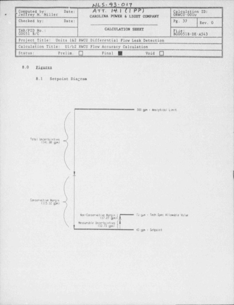
F IJL S - 9 3 < o 17-
Data: A T T. lY. | (| PP)IComEutcdbySillor alculaRWCUOhonID:'Jef rsy M. CAROLINA POWER & LICHT COMPANY- Uo
Checked by: .Date Pg. 37 Rev, O
TAR /PID No.: CALCULATION SIffErp11,h1BDEAS43C0051 B/C BC00.
Project. Title: Units 1&2 RWCU Differential Flow Leak DetectionCalcula5fon Title: 01/02 RWCU Flow Accuracy CalculationStatus: Prelim.-O Final E Void O
8.0 Firutca
8.1 Setpoint Diagram
i
i
300 gpn i Anotytical Liriit
4
Total lincertalaties -
(141.68 gfn)
1r...
IConserative Hergin 4
(115.12 grn)
fNon-Conserva t i 7.1 spn i Tech Spec Alto **te Value '
Hensirable IJncertainties a1r (12.73 gpn) 4
43 gpn i Setpoint