nidaq tools mx - download updates and installers … 1: introduction to nidaq tools mx 3 upgrading...
TRANSCRIPT
NIDAQ Tools MXVersion 1
Data Acquisition for
IGOR PRO
WaveMetrics, Inc.

CopyrightThis manual and the NIDAQ Tools MX are copyrighted by WaveMetrics, Inc. with all rights reserved. Under copyright laws it is illegal for you to copy this manual or the software without written permission from WaveMetrics.WaveMetrics gives you permission to make unlimited copies of the software on any number of machines but only for your own personal use. You may not copy the software for any other reason. You must ensure that only one copy of the software is in use at any given time.
WarrantyWaveMetrics warrants to the registered owner that: 1) the disk on which the software is furnished will be free from defects in material and workmanship under normal use for a period of ninety (90) days from the date of delivery to you. 2) The software will be completely satisfactory to you within a period of ninety (90) days from the date of deliv-ery to you. WaveMetrics does not warrant, guarantee, or make any representations regarding the use or the results of the use of the software or any accompanying written materials in terms of their correctness, accuracy, reliability, currentness or otherwise. The entire risk as to the results and performance of the software and written materials is assumed by you. (Some states do not allow the exclusion or limitation of implied warranties, so the above limitation or exclusion may not apply to you).WaveMetrics offers a 90 day money-back guarantee on products purchased directly from us. If you are not satisfied with the product, please contact us. If we can’t satisfy you, we will refund the purchase price, not including shipping. This guarantee is also available through cooperating vendors. If you did not purchase the product directly from Wave-Metrics, contact your vendor for instructions.
UpdatesWaveMetrics intends to offer periodic updates of the software to you at a reasonable price based on the new function-ality added by the updates.If there are features that you would like to see in subsequent versions of the NIDAQ Tools MX or if you find bugs in the current version, please let us know. We’re committed to providing you with a product that does the job reliably and conveniently.
NoticeApple is a registered service mark of Apple Computer, Inc. Macintosh and Mac OS are registered trademarks of Apple Computer, Inc.Microsoft and Windows are registered trademarks of the Microsoft Corporation.NI-DAQmx is a registered trademark of National Instruments, Inc.Manual Revision: 3/2010 (1.04)© Copyright 2010 WaveMetrics Inc. All rights reserved. Printed in the United States of America.WaveMetrics, Inc.PO Box 2088Lake Oswego, OR 97035Voice: (503) 620-3001FAX: (503) 620-6754 E-mail: [email protected] (Sales information)
[email protected]( Technical support [email protected] (Automated product information)
World-Wide Web:<URL:http://www.wavemetrics.com/>

Table of Contents
Chapter 1: Introduction to NIDAQ Tools MX ..........................1
Overview.................................................................................................................................. 1If You Use a Macintosh... ................................................................................................ 1Otherwise... ....................................................................................................................... 2
Upgrading from NIDAQ Tools? ........................................................................................... 3Getting Ready.......................................................................................................................... 3
The NIDAQmx XOP........................................................................................................ 3The National Instruments Driver .................................................................................. 3Installing NIDAQ Tools MX .......................................................................................... 4Un-Installing NIDAQ Tools MX.................................................................................... 4
To uninstall NIDAQ Tools MX versions older than 1.04.................................... 4To uninstall NIDAQ Tools MX version 1.04 and later........................................ 4
The National Instruments Driver .................................................................................. 4Hardware .......................................................................................................................... 4Device Names................................................................................................................... 5No Hardware?.................................................................................................................. 5
Procedure Files ........................................................................................................................ 5Moving from NIDAQ Tools to NIDAQ Tools MX............................................................. 6
Configuring the Data Acquisition device..................................................................... 6Terminology Changes ..................................................................................................... 6NIDAQ Variables............................................................................................................. 7NIDAQ Tools MX Uses External Operations .............................................................. 7NIDAQ Tools MX Equivalents for NIDAQ Tools Functions .................................... 7Repeated Scanning ........................................................................................................ 10
Chapter 2: Guided Tour of NIDAQ Tools MX ........................13
Introduction ........................................................................................................................... 13Procedure Files ...................................................................................................................... 13The Guided Tour................................................................................................................... 15
i

Acquiring Analog Data into Waves ............................................................................ 15Additional Notes on the Scan Control Panel...................................................... 22
Generating Waveforms from the Analog Outputs ................................................... 23Synchronizing Waveform Generation and Scanning........................................ 27Pre-triggered Scanning .......................................................................................... 28Other Waveform Generation Notes..................................................................... 29
Continuous Analog Input into FIFOs ......................................................................... 29Reviewing a FIFO File............................................................................................ 34Changing the Chart Appearance.......................................................................... 36
Counter/Timers .............................................................................................................. 37Copying the Procedure Files ........................................................................................ 37
Programmer's Tour............................................................................................................... 38Setup ................................................................................................................................ 38Finding the Device Name............................................................................................. 38NIDAQ Tools MX Functions and Operations ........................................................... 39
Variables Created by NIDAQ Tools MX Operations ........................................ 39IMPORTANT- Checking for Errors ............................................................................ 40
Getting a text error message ................................................................................. 40Errors During Execution of NIDAQ Tools MX Operations ............................. 40Method 1: Just use GetRTError............................................................................. 41Method 2: Use try-catch-endtry............................................................................ 41Errors During Execution of NIDAQ Tools MX Functions................................ 42
Analog Input .................................................................................................................. 43Analog Input Using Waves .......................................................................................... 43
Waves for Analog Input Scanning ....................................................................... 47Wave Scaling.................................................................................................... 47Number Type................................................................................................... 48
Scanning order ........................................................................................................ 48Analog Input Using FIFOs ........................................................................................... 48
Stopping Acquisition into FIFOs.......................................................................... 51Gain........................................................................................................................... 52Numeric Type ......................................................................................................... 52FIFO gain ................................................................................................................. 52FIFO Size .................................................................................................................. 53
Other Scanning Options................................................................................................ 53Sample Averaging .................................................................................................. 54Hook functions........................................................................................................ 54
Analog Output: Arbitrary Waveform Generation .................................................... 56Synchronizing Scanning with Waveform Generation.............................................. 57
ii

Chapter 3: NIDAQ Tools MX Technical Issues .....................61
Signal Names ......................................................................................................................... 61RTSI Bus ................................................................................................................................. 62Counter/Timer Conflicts ...................................................................................................... 62Synchronization of Analog Input and Output ................................................................. 63Analog Triggering................................................................................................................. 63
Chapter 4: NIDAQ Tools MX Reference ................................65
Listing of NIDAQ Tools MX Functions and Operations by Category.......................... 65Analog Input .................................................................................................................. 65Analog Output ............................................................................................................... 66Counter/Timer................................................................................................................ 66Digital I/O ....................................................................................................................... 67Error Handling............................................................................................................... 67System Information ....................................................................................................... 67System Control ............................................................................................................... 68Calibration ...................................................................................................................... 68
NIDAQ Tools MX Reference ............................................................................................... 69DAQmx_AI_SetupReader ............................................................................................ 69DAQmx_AO_SetOutputs ............................................................................................. 70DAQmx_CTR_CountEdges.......................................................................................... 72DAQmx_CTR_OutputPulse......................................................................................... 76DAQmx_CTR_Period.................................................................................................... 82DAQmx_CTR_PulseWidth........................................................................................... 82DAQmx_DIO_Config.................................................................................................... 87DAQmx_DIO_WriteNewData..................................................................................... 92DAQmx_Scan ................................................................................................................. 93DAQmx_WaveformGen ............................................................................................. 103fDAQmx_AI_GetReader............................................................................................. 108fDAQmx_AO_UpdateOutputs .................................................................................. 109fDAQmx_ConnectTerminals ..................................................................................... 109fDAQmx_CTR_Finished............................................................................................. 110fDAQmx_CTR_IsFinished.......................................................................................... 110fDAQmx_CTR_IsPulseFinished ................................................................................ 111fDAQmx_CTR_ReadCounter .................................................................................... 111
iii
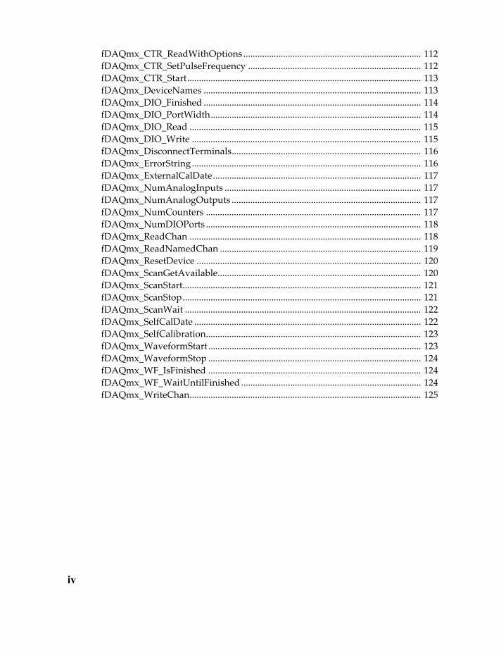
fDAQmx_CTR_ReadWithOptions ............................................................................ 112fDAQmx_CTR_SetPulseFrequency .......................................................................... 112fDAQmx_CTR_Start.................................................................................................... 113fDAQmx_DeviceNames ............................................................................................. 113fDAQmx_DIO_Finished ............................................................................................. 114fDAQmx_DIO_PortWidth.......................................................................................... 114fDAQmx_DIO_Read ................................................................................................... 115fDAQmx_DIO_Write .................................................................................................. 115fDAQmx_DisconnectTerminals................................................................................. 116fDAQmx_ErrorString.................................................................................................. 116fDAQmx_ExternalCalDate......................................................................................... 117fDAQmx_NumAnalogInputs .................................................................................... 117fDAQmx_NumAnalogOutputs ................................................................................. 117fDAQmx_NumCounters ............................................................................................ 117fDAQmx_NumDIOPorts ............................................................................................ 118fDAQmx_ReadChan ................................................................................................... 118fDAQmx_ReadNamedChan ...................................................................................... 119fDAQmx_ResetDevice ................................................................................................ 120fDAQmx_ScanGetAvailable....................................................................................... 120fDAQmx_ScanStart...................................................................................................... 121fDAQmx_ScanStop...................................................................................................... 121fDAQmx_ScanWait ..................................................................................................... 122fDAQmx_SelfCalDate ................................................................................................. 122fDAQmx_SelfCalibration............................................................................................ 123fDAQmx_WaveformStart ........................................................................................... 123fDAQmx_WaveformStop ........................................................................................... 124fDAQmx_WF_IsFinished ........................................................................................... 124fDAQmx_WF_WaitUntilFinished ............................................................................. 124fDAQmx_WriteChan................................................................................................... 125
iv

1In
1
Introduction to the NIDAQ Tools MX
Chapter 1
troduction to NIDAQ Tools MXOverviewThe NIDAQ Tools MX package adds data acquisition support to WaveMetrics' scientific graphing and analysis application Igor Pro. The package supports most multi-function data acquisition devices made by National Instruments for IBM compatible PCs. It is built on top of National Instruments' NI-DAQmx driver software.
To use NIDAQ Tools MX, in addition to the package itself, you must have Igor Pro version 5.04 or later from WaveMetrics, and a data acquisition device from National Instruments. IGOR Pro and the data acquisition device must be purchased separately. NIDAQ Tools MX runs only on computers running the Windows 2000 or Windows XP operating sys-tems.
If You Use a Macintosh...
National Instruments has provided the NI-DAQmx Base driver for a number of platforms, including Macintosh OS X. NI-DAQmx Base is a driver developed using Labview and NI's Hardware DDK. It provides a subset of the functionality available through NI-DAQmx. Unfortunately, we find NI-DAQmx Base is inadequate for an implementation of NIDAQ Tools MX.
To fill the gap, we created a simple, unsupported XOP to access the functionality in the NI-DAQmx Base driver. Problems with bugs in NI-DAQmx Base, and with compatibility from one version of NI-DAQmx Base to another convinced us that we cannot provide the

Chapter 1: Introduction to NIDAQ Tools MX
XOP with Igor Pro. The source code is available on Igor Exchange:
http://www.igorexchange.com/project/NIDAQmxBaseAccess
Otherwise...
The NIDAQ Tools MX package consists of three parts. The fundamental component is the NIDAQmx.xop XOP file, a plug-in software module for Igor Pro that adds external func-tions and operations that can be used from within Igor Pro.
Several Igor Pro procedure files are also included in the package. These files contain Igor Pro user-defined functions that implement various data acquisition tasks using the func-tionality provided by the NIDAQmx XOP.
In addition to the XOP file and the procedure files, there are three help files- NIDAQ Tools MX Help, NIDAQ Tools MX Reference and NIDAQToolsToNIDAQToolsMX. These are Igor Pro-compatible help files, designed to be read on-line using the Igor Pro help system. The NIDAQ Tools MX Help file contains general information about the use of the NIDAQ Tools MX package, including a Guided Tour of the applications provided in the procedure files, and a Programmer's Introduction to the functions added by the NIDAQmx XOP. If you are upgrading from a previous version of NIDAQ Tools, you may find NIDAQTool-sToNIDAQToolsMX helpful.
The NIDAQ Tools MX package can be used in two ways: you can use the control panels implemented by the procedure files, or you can use the functions added to Igor by the NIDAQ XOP directly by writing your own Igor procedures.
The procedure files implement control panels that provide a simple graphical interface to the XOP functions for analog input and output. They solve many data acquisition prob-lems in a simple, straight-forward way.
For more complex problems, or ones requiring a custom solution, use the XOP functions and operations directly in user-defined functions. While the commands can be typed on the Igor command line, you will get mighty tired of typing! You will need to be a reason-ably proficient Igor programmer, and you will need fairly deep knowledge of the data acquisition device and the functions provided by the XOP. The procedure files shipped with NIDAQ Tools MX can serve as a starting point for your own programming. Make copies of the files and modify the copies.
2

Chapter 1: Introduction to NIDAQ Tools MX
Upgrading from NIDAQ Tools?Previous versions of NIDAQ Tools were based on National Instruments' NI-DAQ Soft-ware, version 6 or earlier. The latest DAQ devices from National Instruments are sup-ported only by the new NI-DAQmx driver, so NIDAQ Tools MX is based on that driver.
Because NI-DAQmx is very different from previous versions of NI-DAQ Software, it was not practical to try to make NIDAQ Tools MX compatible with previous versions of NIDAQ Tools. The differences are substantial in detail, but not in overall strategy. If you have written Igor code that uses NIDAQ Tools, you will need to re-write it. You should be able to use the same structure for your code, however.
If you use only the control panels provided by NIDAQ Tools, you should find the control panels that come with NIDAQ Tools MX to be mostly familiar.
For more details, see Moving from NIDAQ Tools to NIDAQ Tools MX on page 6.
Getting ReadyThe NIDAQmx XOP
The NIDAQmx XOP file adds external functions and operations to Igor. These functions and operations provide access to the functionality of the data acquisition device. This access is based on National Instruments' NI-DAQmx® Library. Familiarity with the NI-DAQmx Library documentation and with the manual for the data acquisition device is essential.
The NIDAQmx XOP requires Igor Pro version 5.04 or later. It runs only on IBM PC com-patibles running Windows 2000/XP operating system or later.
The National Instruments Driver
Before you can use NIDAQ Tools MX, you must install the NI-DAQmx driver. If you bought your DAQ device recently, it should have come on a CD shipped with the device. You can also download the driver from National Instruments. It is free after a registration step.
NIDAQ Tools MX requires NI-DAQmx version 7.5 or later. If you have an older version, the NIDAQmx XOP will detect that fact and refuse to run, hopefully with an informative message.
3

Chapter 1: Introduction to NIDAQ Tools MX
Installing NIDAQ Tools MX
An installer program is provided- simply run NIDAQTools MX-Setup. If you have a ver-sion of NIDAQ Tools MX prior to version 1.0.4 (that's before the installer program was created) you may need to remove the old files manually. See the next section for instruc-tions.
Un-Installing NIDAQ Tools MXTo uninstall NIDAQ Tools MX versions older than 1.04
You will most likely need administrator access to your computer.
The files should be in a folder parallel to your Igor Pro folder, most likely in C:\Program Files\WaveMetrics\. Delete the Igor Pro NIDAQ Tools folder, then go to the Igor Pro folder and delete shortcuts to the NIDAQ Tools files. There are several:
In Igor Extensions, there will be a shortcut to NIDAQmx.xop.
In Igor Help Files, there will be shortcuts to NIDAQ Tools Help.ihf and NIDAQ Tools Reference.ihf.
In WaveMetrics Procedures, there will be a shortcut to NIDAQ Tools Proce-dures.
To uninstall NIDAQ Tools MX version 1.04 and later
In the system control panel, find Programs and Features (on Windows XP it will be called Add or Remove Programs). Find Igor NIDAQ Tools MX and select it. Click Uninstall.
The National Instruments Driver
Before you can use NIDAQ Tools MX, you must install the NI-DAQmx driver. If you bought your DAQ device recently, it should have come on a CD shipped with the device. You can also download the driver from National Instruments. It is free.
NIDAQ Tools MX requires NI-DAQmx version 8.04 or later. If you have an older version, the NIDAQmx XOP will detect that fact and refuse to run, hopefully with an informative message.
Hardware
NIDAQ Tools MX works only with Multifunction DAQ devices from National Instru-ments. You must have one of their DAQ devices supported by NI-DAQmx. That would
4
Chapter 1: Introduction to NIDAQ Tools MX
include at least E-series, M-series and S-series. Older devices, such as the PCI-1200 are not supported. If you are in doubt, contact WaveMetrics tech support to make sure.
Device Names
DAQ devices are identified to NI-DAQmx using names. Before using NIDAQ Tools MX, open National Instruments' Measurement and Automation Explorer (MAX), which is installed when you install the NI-DAQmx driver. In MAX, open Devices and Inter-faces->NI-DAQmx Devices. Your DAQ device should be visible; if it is not, you cannot use it.
By default, MAX assigns a name like “dev1” to your device. If you wish, click on the name and edit to change it (you will probably have to click to select the device, then click again to put the name into edit mode).
The name shown in MAX is the name used by NIDAQ Tools MX to refer to your DAQ device. Remember it!
No Hardware?
You can get some idea of how NIDAQ Tools MX works using a simulated device, a feature of NI-DAQmx 7.4 or later. You must install NI-DAQmx first. In National Instruments' Measurement and Automation Explorer (part of the NI-DAQmx installation) open Devices and Interfaces. Right-click on NI-DAQmx Devices and select Create New NI-DAQmx Device->NI-DAQmx Simulated Device.
The timing will be wrong - simulated devices return data at a high rate regardless of rate settings. You won't be able to use triggers, etc., since you don't have access to hardware connections. But you should be able to get the basic idea.
Procedure FilesThe NIDAQ Tools MX package comes with several procedure files containing IGOR func-tions and macros to help you use the NIDAQ Tools MX functionality. Most of the proce-dure files create IGOR Pro control panels. For some applications this is all you will need.
The procedure files can be used in two ways. In the Guided tour (see page 15), you will be directed to use the #include statement to make the procedure files part of your experi-ment. In this case, the procedures can be compiled and used, but you cannot easily modify the files.
5
Chapter 1: Introduction to NIDAQ Tools MX
If you want to use the procedure files as the basis of your own programming, it is best to make a copy of the file. Store the copy in a convenient location, preferably in a folder out-side the Igor Pro folder. Then create a shortcut for the file and put the shortcut into the User Procedures folder. Your file can then be loaded into Igor with a #include statement. Modify your own copy of the file. This method will protect your file in case you install a new version of IGOR.
We do not recommend that you open the supplied procedure files directly using the ‘Pro-cedure...’ item from the ‘Open File’ selection in the ‘File’ menu. If you do this, and you alter the files, you have changed the files that were shipped with NIDAQ Tools MX. If you later install an update, you may overwrite your modifications.
Moving from NIDAQ Tools to NIDAQ Tools MXBecause NI-DAQmx is very different from previous versions of NI-DAQ Software, it was not practical to try to make NIDAQ Tools MX compatible with previous versions of NIDAQ Tools. The differences are substantial in detail, but not in overall strategy. If you have written Igor code that uses NIDAQ Tools, you will need to re-write it. You should be able to use the same structure for your code, however.
If you use only the control panels provided by NIDAQ Tools, you should find the control panels that come with NIDAQ Tools MX to be mostly familiar.
Configuring the Data Acquisition device
With NIDAQ Tools version 1.5 and earlier, it was necessary to use the NIDAQ Configura-tion dialog to tell the NIDAQ XOP about the characteristics of your DAQ device.
National Instruments has done quite a good job of improving the consistency in the inter-face to different kinds of hardware. The consequence is that there is no configuration dia-log, and no configurations to worry about.
That is not to say there are no difference between devices. If you try to do something that your hardware doesn't support, the NI-DAQmx driver will issue an error.
So- ALWAYS check for errors in your code.
Terminology Changes
National Instruments has changed some of their terminology in order to make it more
6
Chapter 1: Introduction to NIDAQ Tools MX
descriptive. You can read about these changes in the NI-DAQmx documentation, under the heading, “Translation Guide–Traditional NI-DAQ (Legacy) to NI-DAQmx”.
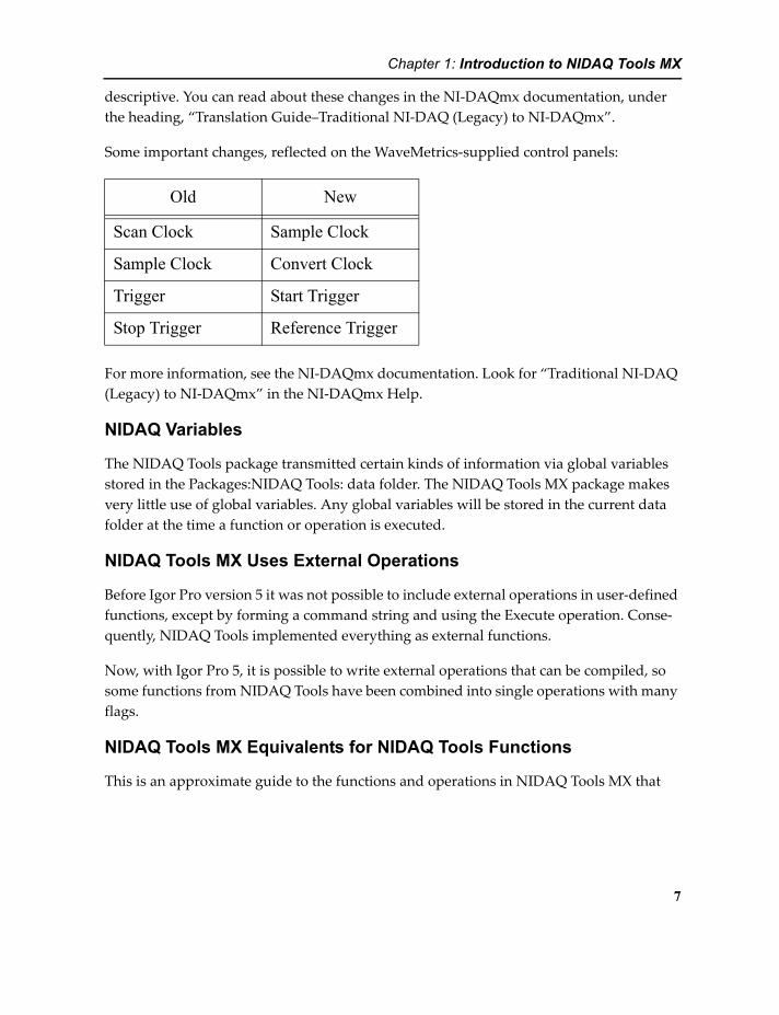
Some important changes, reflected on the WaveMetrics-supplied control panels:
Old New
Scan Clock Sample Clock
Sample Clock Convert Clock
Trigger Start Trigger
Stop Trigger Reference Trigger
For more information, see the NI-DAQmx documentation. Look for “Traditional NI-DAQ (Legacy) to NI-DAQmx” in the NI-DAQmx Help.
NIDAQ Variables
The NIDAQ Tools package transmitted certain kinds of information via global variables stored in the Packages:NIDAQ Tools: data folder. The NIDAQ Tools MX package makes very little use of global variables. Any global variables will be stored in the current data folder at the time a function or operation is executed.
NIDAQ Tools MX Uses External Operations
Before Igor Pro version 5 it was not possible to include external operations in user-defined functions, except by forming a command string and using the Execute operation. Conse-quently, NIDAQ Tools implemented everything as external functions.
Now, with Igor Pro 5, it is possible to write external operations that can be compiled, so some functions from NIDAQ Tools have been combined into single operations with many flags.
NIDAQ Tools MX Equivalents for NIDAQ Tools Functions
This is an approximate guide to the functions and operations in NIDAQ Tools MX that
7

Chapter 1: Introduction to NIDAQ Tools MX
replace functions you used with NIDAQ Tools 1.5 and earlier.
NIDAQ Tools 1.5 NIDAQ Tools MX
Scanning
fNIDAQ_ScanWaves DAQmx_Scan WAVES="parameterstring" (page 93)
fNIDAQ_ScanAsyncStart DAQmx_Scan/BKG WAVES="parameterstring"
fNIDAQ_ScanWavesRepeat DAQmx_Scan/RPT WAVES="parameterstring"DAQmx_Scan/RPTC WAVES="parameterstring"
fNIDAQ_ScanFIFO DAQmx_Scan FIFO="parameterstring"
fNIDAQ_ResetScan fDAQmx_ScanStop (page 121)
fNIDAQ_ScanFIFOStop fDAQmx_ScanStop
fNIDAQ_StopFillRepeat fDAQmx_ScanStop
fNIDAQ_Conf_HW_Analog_Trigger DAQmx_Scan/TRIG={trigsrc, 2 or 3 ...} (page 93)
Waveform Generation
fNIDAQ_WaveformGen DAQmx_WaveformGen (page 103)
fNIDAQ_WFStop fDAQmx_WaveformStop (page 124)
fNIDAQ_WFReset fDAQmx_WaveformStop
Digital I/O
There is just one interface for digital I/O in NI-DAQmx, and there is just one operation in NIDAQ Tools MX to set up digital I/O: DAQmx_DIO_Config. To set up lines and ports, you specify ter-minals in the LineSpec parameter. For buffered I/O, use the /WAVE or /FIFO flag.
fNIDAQ_DIG_Port_Config DAQmx_DIO_Config (page 87)
fNIDAQ_DIG_Line_Config DAQmx_DIO_Config
fNIDAQ_DIG_Grp_Config DAQmx_DIO_Config
fNIDAQ_DIG_Grp_Mode DAQmx_DIO_Config
fNIDAQ_DIG_Scan_Setup DAQmx_DIO_Config /WAVE or /FIFO
fNIDAQ_DIG_In_Line fDAQmx_DIO_Read (page 115)
8

Chapter 1: Introduction to NIDAQ Tools MX
fNIDAQ_DIG_In_Port fDAQmx_DIO_Read
fNIDAQ_DIG_In_Group fDAQmx_DIO_Read
fNIDAQ_DIG_Block_In fDAQmx_DIO_Read
fNIDAQ_DIG_Out_Line fDAQmx_DIO_Write (page 115)
fNIDAQ_DIG_Out_Port fDAQmx_DIO_Write
fNIDAQ_DIG_Out_Group fDAQmx_DIO_Write
fNIDAQ_DIG_Block_Out fDAQmx_DIO_Write
Counter/Timers
Counter/Timers in NI-DAQmx use just one unified interface; the older counters that were previ-ously programmed using fNIDAQ_ICTR and fNIDAQ_CTR are obsolete.
fNIDAQ_ICTR_xxx obsolete: see DAQmx_CTR_xxx
fNIDAQ_CTR_xxx obsolete: see DAQmx_CTR_xxx
fNIDAQ_GPCTR_Set_Application DAQmx_CTR_CountEdges (page 72)DAQmx_CTR_OutputPulse (page 76)DAQmx_CTR_Period (page 82)DAQmx_CTR_PulseWidth (page 82)
fNIDAQ_GPCTR_Retrieve_Data automatic in background
fNIDAQ_GPCTR_Counting_Finished fDAQmx_CTR_Finished (page 110)
Error Reporting
fNIDAQ_ErrorString fDAQmx_ErrorString (page 116)
System Functions
fNIDAQ_Select_Signal Specify signal paths with various flags for each operation. See Signal Names on page 61.
fNIDAQ_BoardReset fDAQmx_ResetDevice (page 120)
Configuration functions
No longer needed
Information Functions
NIDAQ Tools 1.5 NIDAQ Tools MX
9
Chapter 1: Introduction to NIDAQ Tools MX
Repeated Scanning
In the old NIDAQ Tools, we provided a function fNIDAQ_ScanWavesRepeat that was intended to emulate an oscilloscope. This was done by scanning continuously; when the waves were filled, the data was put into the waves starting with point 0. This over-wrote the previous data, giving an oscilloscope-like display.
However, because this was implemented using continuous scanning, if you used a trig-ger, the trigger only worked for the first scan; repeated scans simply continued the scan-ning at the selected scanning rate. This is not like an oscilloscope, and many people complained.
Consequently, in NIDAQ Tools MX, we provide the operation DAQmx_Scan (page 93) with the /RPT flag. This flag implements repeated scanning by stopping the data acquisi-tion task and re-starting it immediately. This has the happy effect of causing the trigger signal to be honored for every repeated scan. It has the unhappy effect of creating a slight and indeterminate delay between the last point of one scan and the first point of the previ-ous scan. Further, if you don’t use a trigger, and the scanning rate is sufficiently slow, the first point of the next scan occurs too soon.
If you need the original behavior of NIDAQ Tools fNIDAQ_ScanWavesRepeat function, use the /RPTC flag (the C stands for “continuous”). It emulates the continuous acquisition
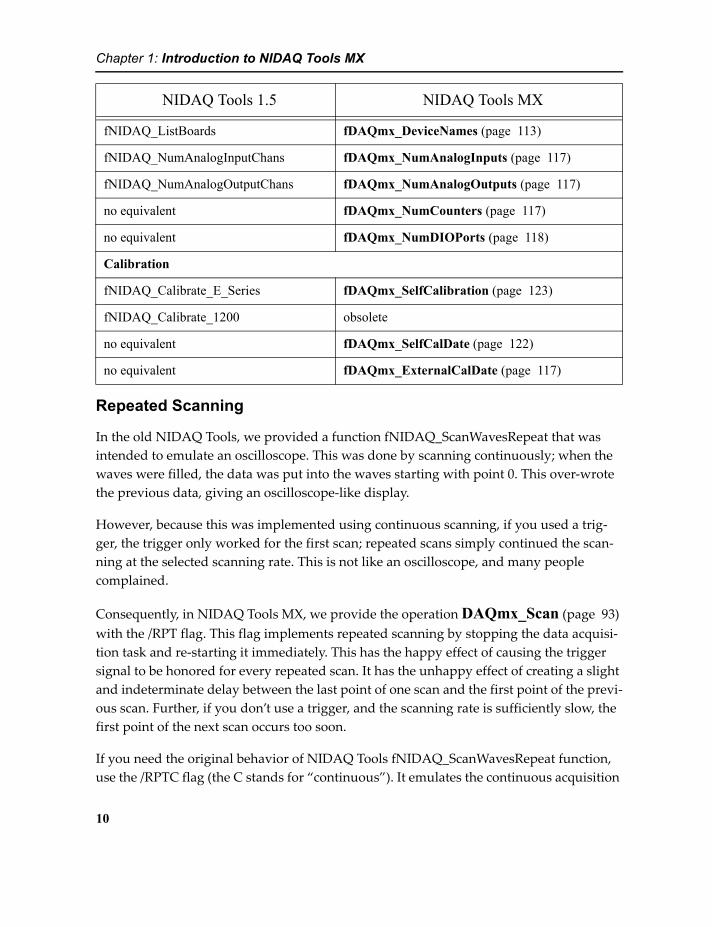
fNIDAQ_ListBoards fDAQmx_DeviceNames (page 113)
fNIDAQ_NumAnalogInputChans fDAQmx_NumAnalogInputs (page 117)
fNIDAQ_NumAnalogOutputChans fDAQmx_NumAnalogOutputs (page 117)
no equivalent fDAQmx_NumCounters (page 117)
no equivalent fDAQmx_NumDIOPorts (page 118)
Calibration
fNIDAQ_Calibrate_E_Series fDAQmx_SelfCalibration (page 123)
fNIDAQ_Calibrate_1200 obsolete
no equivalent fDAQmx_SelfCalDate (page 122)
no equivalent fDAQmx_ExternalCalDate (page 117)
NIDAQ Tools 1.5 NIDAQ Tools MX
10

Chapter 1: Introduction to NIDAQ Tools MX
action of the fNIDAQ_ScanWavesRepeat function. See the Details section of the DAQmx_Scan documentation for more information. An example is given in the NIDAQ Tools MX Guided Tour in the Programmer’s Introduction on page 46.
11

Chapter 1: Introduction to NIDAQ Tools MX
12

2
Guided Tour of NIDAQ Tools MX
Chapter 2
2Guided Tour of NIDAQ Tools MXIntroductionThis chapter provides a guided introduction to many of the features and components of NIDAQ Tools MX. It is not exhaustive- there are many features that are not covered. But this chapter will introduce you to the style of NIDAQ Tools MX and to the most-used functionality.
There are two main parts- the Guided Tour (starting on page 15) and the Programmer’s Guide (starting on page 38). The Guided Tour presents high-level components imple-mented as user-defined procedure files that create control panels to provide a graphical user interface to commonly-used functionality.
Those who want a specialized interface, or who want to add functionality not available in the shipping procedure files will need to program their own. The Programmer’s Introduc-tion offers an introduction to the low-level NIDAQ Tools MX functionality that a pro-grammer will use.
Procedure FilesThe NIDAQ Tools MX package comes with several procedure files containing IGOR user-defined functions to help you use the NIDAQ Tools functionality. Some of the procedure files create IGOR Pro control panels that provide access to the analog input and output, and counter/timer functions of the NIDAQmx XOP. Other procedure files contain utility

Chapter 2: Guided Tour of NIDAQ Tools MX
functions, and some are simply examples of the use of various aspects of NIDAQ Tools MX.
The supplied control panel procedures may do all that you need them to do. If you need something different you will need to create your own procedures. In that case the sup-plied files can serve as the basis for your own customized data acquisition programs.
If you have not already installed the NIDAQ Tools MX package on your hard disk, do so now. See Installing NIDAQ Tools MX on page 4 for instructions.
Different components of the package must be installed in different places. For instruc-tions, see the READ ME files in the NIDAQ Tools MX distribution.
Most of the procedure files implement a control panel to provide easy access to the data acquisition features. The files that do this are:
NIDAQmxWaveScanProcs.ipf NIDAQmxWaveFormGenProcs.ipf NIDAQmxFIFOProcs.ipf NIDAQmxFIFOReviewProcs.ipf NIDAQmxRepeatedScanProcs.ipf NIDAQmxPulseTrainGenerator.ipf NIDAQmxSimpleEventCounter.ipf
Other files are #include'ed by the files above, and provide support services to these files. They are not explicitly mentioned in the Guided Tour, but they must be present in the NIDAQ Procedures folder for everything to work correctly. They include:
NIDAQmxChannelSelectorProcs.ipf NIDAQmxChartAppearanceTab.ipf NIDAQmxUtilities.ipf NIDAQmxUtilities2.ipf
You can use these procedure files as-is if they do what you want them to do. You are also welcome to use them as the basis for your own Igor programs customized to suit your particular needs, but you should make your own copy of these files and modify your copy, not the originals.
In the Guided Tour, you will be directed to use the #include statement to make the proce-dure files part of your experiment. In this case, the procedures can be compiled and used, but you cannot modify the files.
14

Chapter 2: Guided Tour of NIDAQ Tools MX
We do not recommend that you open the procedure files directly using the ‘Procedure...’ item from the ‘Open File’ selection in the ‘File’ menu. If you do this, and you alter the files, you have changed the files that were shipped with NIDAQ Tools. If you later install an update, you may overwrite your modifications.
The Guided TourThroughout the Guided Tour, a pointing finger is used to indicate an instruction that you should complete exactly as directed.
It is best to start this Guided Tour with a clean slate:
Launch IGOR. If IGOR is running, quit and launch IGOR again.
If you don't have a National Instruments data acquisition device, you may want to do the Guided Tour with a simulated device. See No Hardware? on page 5 for details.
Acquiring Analog Data into Waves
This section of the guided tour will assume that nothing is connected to the external con-nector on the data acquisition device. It is best if you can use a terminal break-out panel or connector pad so that you can get to the signal connections. If you touch the analog inputs, you can introduce a (noise) signal.
Naturally, if you are using a simulated device, you will have no connector or break-out panel. The NI-DAQmx driver will return fake data.
Display the main procedure window by select-ing the Procedure Window item from the Win-dows menu. Enter the following in the procedure window:
#include <NIDAQmxWaveScanProcs>
Click the Compile button at the bottom of the procedure window and close the window.
Compiling adds a NIDAQ Tools MX item to the Data menu. The NIDAQ Tools MX item brings up a sub-menu containing items added by the various NIDAQ Tools MX procedure files. The NIDAQmxWaveScan-Procs procedure file adds ‘Wave Scan Controls’:
15

Chapter 2: Guided Tour of NIDAQ Tools MX
The procedure files described here are designed to work with one device. If you have more than one device configured for use, you can use more than one copy of a given con-trol panel, one for each device.
Select the Wave Scan Controls menu item.
If you have more than one device available, you will first see a panel to select which device you want to work with:
Our system has a PCI-MIO16XE-50 and a PCI-6229, named “MIO16” and “PCI6229”, respectively. If you have only one device configured, you will not see this panel.
The Scan Control panel provides an interface for controlling analog input into waves. It builds and executes a command line that calls the operation DAQmx_Scan (page 93). It is pic-tured to the right.
The panel provides areas for specifying the number of samples to acquire, sampling rates, channels to scan, etc. Even though it doesn't look like it, you can re-size the control panel by dragging the lower-right corner. Resizing the control panel will change the size of the channel selector list box.
The box at the bottom that says “No Error” dis-plays error messages. When you do something that works correctly it says “No Error”. To get you started with the correct attitude, the panel displays the message “No Error” when it is cre-ated.
First, settings that control sampling:
Set Number of samples to 100.
16
Chapter 2: Guided Tour of NIDAQ Tools MX
Set Averaging Samples to 1.
Set the Sample Period to 0.1.
These settings ask for a total of 100 samples at intervals of 0.1 second, so the total time taken will be 10 seconds.
Make sure the values for Convert Period and Post-trigger Samples are both zero.
These settings instruct the NIDAQmx XOP to select default values. The meanings of these settings are discussed below. Because Post-trigger samples is set to zero, the panel will ignore the settings for Reference Trigger Source, Type, Level 1 and Level 2 just below.
The Mode: popup should be set to ‘One shot’; if it is not, set it now.
The ‘Return Immediately’, 'Start Trigger’, ‘Sample Clock’ and ‘Convert Clock’ checkboxes should not be checked.
Because the 'Start Trigger’, ‘Sample Clock’ and ‘Convert Clock’ checkboxes are all unchecked, the rest of the settings to the right of the checkboxes will be ignored.
We now move on to selecting channels to scan. This is done in the list in the lower part of the panel.
Note: The Scan Control panel can be re-sized by dragging the lower-right corner (there is no indication that this is the case). Making the panel taller will display more rows in the list. Making it wider gives you more room to view wave names.
Select channels 0 and 1 by checking the appropriate check boxes in the left column of the list.
You must provide a name for a wave to receive acquired data from each selected channel. The panel starts up with the names set to “Inputn” where n is the channel number.
For now, simply use the default names Input0, Input1, etc.
You can change the names by clicking in a cell in the column labelled 'Destination Wave'. Clicking the cell will enter edit mode, and you can type a new name. You can make the wave names anything you like, as long as they are legal IGOR wave names.
Note: You can enter a name with liberal characters and any necessary single quote marks will be added automatically. For more information about liberal names,
17

Chapter 2: Guided Tour of NIDAQ Tools MX
read about Object Names in the Igor Help.
Note: NIDAQ Tools supports Igor data folders. If you enter a data folder path with the wave name, the wave will be created in that path (if it exists). If there is no path, a wave with the given name will be made in whatever is the current data folder at the time the Start button is clicked.
The menu below the list allows you to select a pre-existing wave. The wave's name with full data folder path will be entered into the Destination Wave column in whatever row is selected.
When scanning is started, new waves will be made with these names. If waves already exist with these names, they will be overwritten.
Make sure Min V and Max V are set to -10 and 10. To set a value for a single cell, right-click in the cell. To set all channels to the same value, right-click in the title cell.
Note: Min V and Max V are used by the NI-DAQmx driver to choose a gain for the channel. In actual use, you should set these to the smallest value that you know will be appropriate to your signals. The driver will use the information to choose the best gain setting available on your DAQ device.
Make sure Type is set appropriately:
By default, this is set to “Diff” to select differential input mode. Some DAQ devices may not support differential mode (in particular, the S-series devices may require Pseudo-dif-ferential mode). To change the setting, right-click on the cell you want to change to dis-play a menu with choices of Diff, RSE (for Referenced Single-Ended), NRSE (Non-Referenced Single-Ended) or PDIFF (for Pseudo Differential). If these choices don't mean anything to you, read the section of the manual for your DAQ device that talks about con-necting signals to the device.
Click the Start button.
The Start button is replaced by a message telling you “To stop, press Abort button”. The beach-ball spins and the status box next to the Start button turns red and reads “Scan-ning” while data is acquired. After 10 seconds, the Start button reappears and the status box turns green and reads “Ready”. (If you are using a simulated device, since the data are fake, it doesn't take 10 seconds. The timing of a simulated device is entirely dependent on the speed of your machine.)
Gee whiz, is that it? I didn't see anything happen.
18
Chapter 2: Guided Tour of NIDAQ Tools MX
Select Data Browser from the Data menu.
You will see two waves in the root data folder- Input0 and Input1. If you have the Info pane displayed, clicking on the wave names shows that they are both single precision floating-point waves (FP32) and have a length of 100 points.
Make a graph of the two waves by executing this command on the Igor command line:
Display Input0, Input1
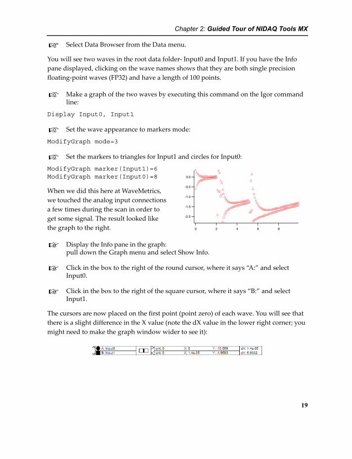
Set the wave appearance to markers mode:
ModifyGraph mode=3
Set the markers to triangles for Input1 and circles for Input0:
ModifyGraph marker(Input1)=6
-2.0
-1.5
-1.0
-0.5
0.0
86420
ModifyGraph marker(Input0)=8
When we did this here at WaveMetrics, we touched the analog input connections a few times during the scan in order to get some signal. The result looked like the graph to the right.
Display the Info pane in the graph: pull down the Graph menu and select Show Info.
Click in the box to the right of the round cursor, where it says “A:” and select Input0.
Click in the box to the right of the square cursor, where it says “B:” and select Input1.
The cursors are now placed on the first point (point zero) of each wave. You will see that there is a slight difference in the X value (note the dX value in the lower right corner; you might need to make the graph window wider to see it):
19
Chapter 2: Guided Tour of NIDAQ Tools MX
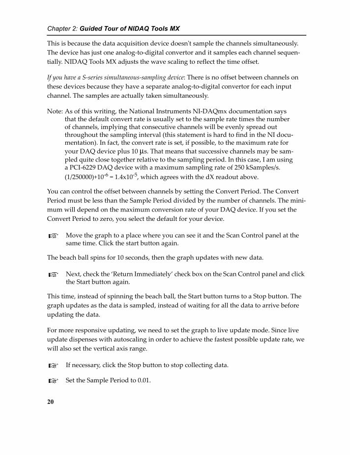
This is because the data acquisition device doesn't sample the channels simultaneously. The device has just one analog-to-digital convertor and it samples each channel sequen-tially. NIDAQ Tools MX adjusts the wave scaling to reflect the time offset.
If you have a S-series simultaneous-sampling device: There is no offset between channels on these devices because they have a separate analog-to-digital convertor for each input channel. The samples are actually taken simultaneously.
Note: As of this writing, the National Instruments NI-DAQmx documentation says that the default convert rate is usually set to the sample rate times the number of channels, implying that consecutive channels will be evenly spread out throughout the sampling interval (this statement is hard to find in the NI docu-mentation). In fact, the convert rate is set, if possible, to the maximum rate for your DAQ device plus 10 μs. That means that successive channels may be sam-pled quite close together relative to the sampling period. In this case, I am using a PCI-6229 DAQ device with a maximum sampling rate of 250 kSamples/s. (1/250000)+10-6 = 1.4x10⁻⁵, which agrees with the dX readout above.
You can control the offset between channels by setting the Convert Period. The Convert Period must be less than the Sample Period divided by the number of channels. The mini-mum will depend on the maximum conversion rate of your DAQ device. If you set the Convert Period to zero, you select the default for your device.
Move the graph to a place where you can see it and the Scan Control panel at the same time. Click the start button again.
The beach ball spins for 10 seconds, then the graph updates with new data.
Next, check the ‘Return Immediately’ check box on the Scan Control panel and click the Start button again.
This time, instead of spinning the beach ball, the Start button turns to a Stop button. The graph updates as the data is sampled, instead of waiting for all the data to arrive before updating the data.
For more responsive updating, we need to set the graph to live update mode. Since live update dispenses with autoscaling in order to achieve the fastest possible update rate, we will also set the vertical axis range.
If necessary, click the Stop button to stop collecting data.
Set the Sample Period to 0.01.
20

Chapter 2: Guided Tour of NIDAQ Tools MX
In the Mode popup, select 'Repeated'.
The ‘Return Immediately’ check box is replaced by a checkbox labelled 'Use Continuous Acquisition'. Return Immediately is irrelevant to repeated mode because the XOP always returns immediately during repeated acquisition. The Use Continuous Acquisition check-box controls a rather abstruse detail that will be discussed later.
Enter these commands on the command line and press enter:
ModifyGraph live=1SetAxis left -10, 10
Click the Start button.
The Start button turns to a Stop button, and the status box indicates Scanning. The hori-zontal range of the graph is wrong.
Enter this command on the command line and press enter:
SetAxis/A bottom
Since the graph is in live mode, autoscaling is disabled. The SetAxis/A bottom command will correct the horizontal axis scaling.
Watch your graph. If you want, click in the graph to bring it to the front. Now, once per second (100 samples times 0.01 seconds per sample) the graph updates with new data. This is like a slow oscilloscope. You may not be able to see much change from one trace to the next- try putting your fingers on the inputs to generate some noise.
Click the Stop button to stop collecting data.
Save the experiment to your hard drive.
You can take a break now if you want.
Additional Notes on the Scan Control Panel
In addition to the obvious ways to change settings in the panel, the Select Channels list provides contex-tual menus for certain settings. You were already directed to use a contextual menu to set the input type. Other title cells accept a right-click to affect all
21
Chapter 2: Guided Tour of NIDAQ Tools MX
channels, as well. The picture to the right shows the contextual menu that appears if you right-click in the Input Channel title cell.
If you set a number greater than one in the Averaging Samples box, each data point in the resulting waves will be the average of that many readings. The data points will still have the specified time interval, so that means that this causes the aggregate scanning rate to be increased by the same factor.
If the Start Trigger checkbox is checked, sampling won't start until a trigger signal is asserted. The devices supported by NI-DAQmx are very flexible- you can tell the driver to connect a given signal to a wide variety of connector pins or use a signal internal to the DAQ device. You specify the source for the trigger signal by entering a signal path in the box labelled Trigger Source. The menu to the right of the Trigger Source box has some commonly-used possibilities. See Synchronizing Waveform Generation and Scanning on page 26 for an example that uses triggering.
You can also control when samples are taken using your own external signal, or one of several signals internal to the device. You do this by checking the Sample Clock checkbox and entering a signal source in the Clock Source box. You might do this to synchronize scanning to an external process such as a rotating shaft.
Finally, you can control when analog-to-digital conversions occur on each channel using the Convert Clock checkbox. However, Sample Clock is the appropriate clock for most applications.
These capabilities are beyond the scope of this Guided Tour; see the reference information for the operation DAQmx_Scan (page 93) and National Instruments' documentation for the NI-DAQmx driver.
Generating Waveforms from the Analog Outputs
The NIDAQmx XOP supports arbitrary waveform generation. Using IGOR waves to set the waveform shape, it is possible to generate virtually any periodic waveform you wish at the analog outputs.
If you are using a simulated DAQ device, this section will not have much interest to you. You can perform all the steps, but since you aren't using real hardware, you can't get any analog output.
22
Chapter 2: Guided Tour of NIDAQ Tools MX
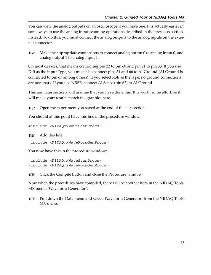
You can view the analog outputs on an oscilloscope if you have one. It is actually easier in some ways to use the analog input scanning operations described in the previous section instead. To do this, you must connect the analog outputs to the analog inputs on the exter-nal connector.
Make the appropriate connections to connect analog output 0 to analog input 0, and analog output 1 to analog input 1.
On most devices, that means connecting pin 22 to pin 68 and pin 21 to pin 33. If you use Diff as the input Type, you must also connect pins 34 and 66 to AI Ground (AI Ground is connected to pin 67 among others). If you select RSE as the type, no ground connections are necessary. If you use NRSE, connect AI Sense (pin 62) to AI Ground.
This and later sections will assume that you have done this. It is worth some effort, as it will make your results match the graphics here.
Open the experiment you saved at the end of the last section.
You should at this point have this line in the procedure window:
#include <NIDAQmxWaveScanProcs>
Add this line:
#include <NIDAQmxWaveFormGenProcs>
You now have this in the procedure window:
#include <NIDAQmxWaveScanProcs>#include <NIDAQmxWaveFormGenProcs>
Click the Compile button and close the Procedure window.
Now when the procedures have compiled, there will be another item in the NIDAQ Tools MX menu: ‘Waveform Generator’.
Pull down the Data menu and select ‘Waveform Generator’ from the NIDAQ Tools MX menu.
23
Chapter 2: Guided Tour of NIDAQ Tools MX
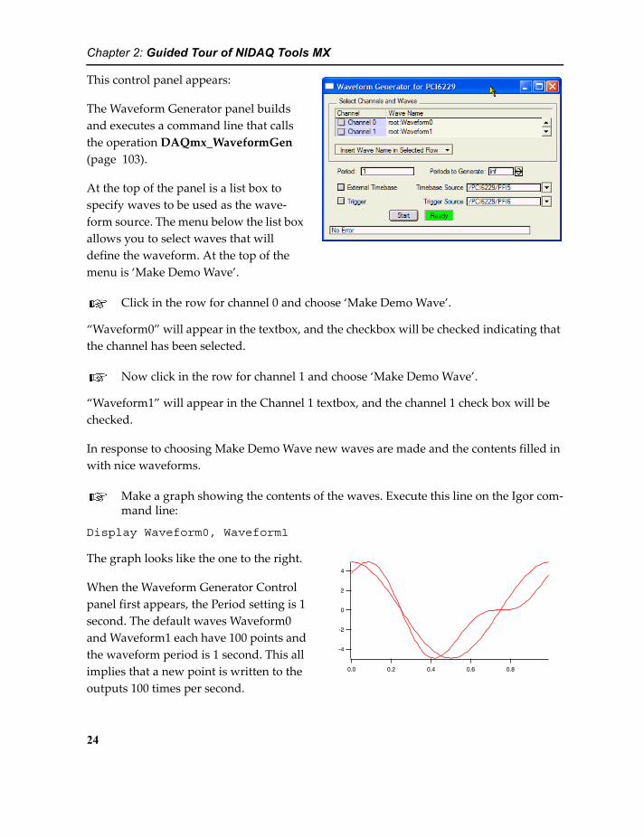
This control panel appears:
The Waveform Generator panel builds and executes a command line that calls the operation DAQmx_WaveformGen (page 103).
At the top of the panel is a list box to specify waves to be used as the wave-form source. The menu below the list box allows you to select waves that will define the waveform. At the top of the menu is ‘Make Demo Wave’.
Click in the row for channel 0 and choose ‘Make Demo Wave’.
“Waveform0” will appear in the textbox, and the checkbox will be checked indicating that the channel has been selected.
Now click in the row for channel 1 and choose ‘Make Demo Wave’.
“Waveform1” will appear in the Channel 1 textbox, and the channel 1 check box will be checked.
In response to choosing Make Demo Wave new waves are made and the contents filled in with nice waveforms.
Make a graph showing the contents of the waves. Execute this line on the Igor com-mand line:
Display Waveform0, Waveform1
The graph looks like the one to the right.
-4
-2
0
2
4
0.80.60.40.20.0
When the Waveform Generator Control panel first appears, the Period setting is 1 second. The default waves Waveform0 and Waveform1 each have 100 points and the waveform period is 1 second. This all implies that a new point is written to the outputs 100 times per second.
24

Chapter 2: Guided Tour of NIDAQ Tools MX
Click the Start button.
As with the Scan Control Panel, the Start button turns to a Stop button, and the status box turns to Running. Now we want to see what's happening.
Make a graph to display scanning results by executing the following commands:
Display Input0, Input1ModifyGraph mode=3ModifyGraph marker(Input1)=6ModifyGraph marker(Input0)=8ModifyGraph live=1SetAxis left -5, 5
This sequence will result in a graph having open circles for analog input 0 and triangles for analog input 1, and a vertical axis range of -5 to 5, displaying in live mode.
In the Scan Control panel (you still have it, right? If you don't, go back to the previ-ous section to make it) set the Number of Samples to 100 and the Scan Interval to 0.01. Select Channel 0 and Channel 1. Select Repeated mode and click the Start but-ton.
The graph should now look similar to the graph shown above (but with markers). On any reasonably fast machine, each time it starts a new trace, the waveforms shift to the right one data point. That's because of the way the repeated scan works- when all the data for a scan have been acquired, the scan task is stopped and immediately re-started. For moder-ate scanning rates, this takes less time than the sample interval, so the interval between the end of a scan and the start of a new scan is less than the time between samples.
On the Waveform Generator Control panel, click the Stop button.
The graph now shows two horizontal lines of markers.
Click the Start button on the Waveform Generator control panel.
The nice curves come back.
On the Scan Control panel, click the Stop button. Change the Number of Samples to 200 and the Sample Period to 0.005. Click the Start Button.
The graph now looks much as it did before, but now each data point is doubled. The gen-erated output waveform is actually a series of stair-steps- one step for each point in the
25

Chapter 2: Guided Tour of NIDAQ Tools MX
waves controlling the output waveforms. Because the scanning is being done at twice the rate of the analog output updates, there are two scanned points for each step.
Note also that the traces tend to shift slightly with each repeated scan. We set up the scan and the waveform generation so that they take the same amount of time. But the repeated scan starts over again as soon as it finishes a scan, and the time it takes to re-start is unre-lated to the scanning rate.
Click the Stop button on the Scan control panel. Check the Use Continuous Acquisi-tion and click the Start button.
The scanned waveform doesn't change at all.
Click the Stop button on the Waveform Generator panel.
The waveforms on the graph go flat.
With the Use Continuous Acquisition checkbox checked, the repeated scans are continu-ous. The first point of each scan is one sample period after the last period of the previous scan, so the scan and waveform generation stay in sync.
Click the Stop button on the Waveform Generator panel. Enter 1 in the Periods to Generate box and click the Start button.
The scan briefly displays the waveform, then it disappears because the waveform genera-tion stopped after one period.
Click the Start button again.
Each time you do this, it generates a single period of the waveform again, starting at some random point in the scan.
Synchronizing Waveform Generation and Scanning
Sometimes you need to start a scan and a waveform generation at the same time. You can do this with the appropriate triggers.
On the Scan Control panel, click Stop. Un-check the Use Continuous Acquisition checkbox. Click the Start Trigger checkbox. Pop up the Trigger Source menu and select /ao/StartTrigger. Make sure the mode is still set to Repeated. Click the Start button.
On the Waveform Generator panel, click Start.
26
Chapter 2: Guided Tour of NIDAQ Tools MX
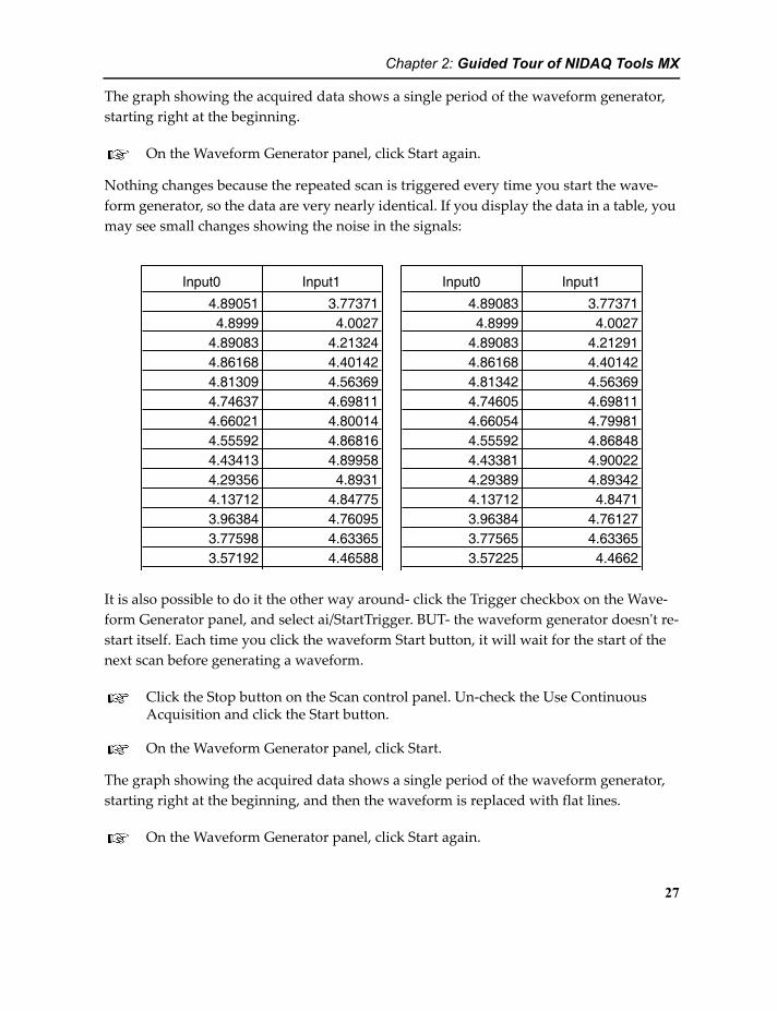
The graph showing the acquired data shows a single period of the waveform generator, starting right at the beginning.
On the Waveform Generator panel, click Start again.
Nothing changes because the repeated scan is triggered every time you start the wave-form generator, so the data are very nearly identical. If you display the data in a table, you may see small changes showing the noise in the signals:
Input0 Input1
4.89051 3.773714.8999 4.0027
4.89083 4.213244.86168 4.401424.81309 4.563694.74637 4.698114.66021 4.800144.55592 4.868164.43413 4.899584.29356 4.89314.13712 4.847753.96384 4.760953.77598 4.633653.57192 4.46588
Input0 Input1
4.89083 3.773714.8999 4.0027
4.89083 4.212914.86168 4.401424.81342 4.563694.74605 4.698114.66054 4.799814.55592 4.868484.43381 4.900224.29389 4.893424.13712 4.84713.96384 4.761273.77565 4.633653.57225 4.4662
It is also possible to do it the other way around- click the Trigger checkbox on the Wave-form Generator panel, and select ai/StartTrigger. BUT- the waveform generator doesn't re-start itself. Each time you click the waveform Start button, it will wait for the start of the next scan before generating a waveform.
Click the Stop button on the Scan control panel. Un-check the Use Continuous Acquisition and click the Start button.
On the Waveform Generator panel, click Start.
The graph showing the acquired data shows a single period of the waveform generator, starting right at the beginning, and then the waveform is replaced with flat lines.
On the Waveform Generator panel, click Start again.
27
Chapter 2: Guided Tour of NIDAQ Tools MX
The waveform appears from a random point on the scan, then disappears again.
When a repeated scan is done in continuous acquisition mode, the scanning never stops to wait for the trigger. Any trigger works only for the very first repeated scan.
So, if you have a good trigger signal for your repeated waveform, it is usually best not to use continuous acquisition. If you don't have a trigger for every repeat of the signal you are trying to look at, do use continuous acquisition mode. For details, see the documenta-tion for the operation DAQmx_Scan (page 93).
Pre-triggered Scanning
Sometimes you need to start scanning some set amount of time before a trigger event.
Stop the scan. The waveform generator doesn't need to be stopped because it was set to generate a single period.
On the Scan Control panel, un-check the Start Trigger checkbox.
Select One-shot in the Mode menu. Check the Return Immediately checkbox.
Set Post-trigger samples to 150 (you are still acquiring 200 samples, right?).
Popup the Reference Trigger Source menu and select /ao/StartTrigger.
Click the Start button.
The Start button turns to Stop, and it tells you it's scanning, but nothing happens in the graph.
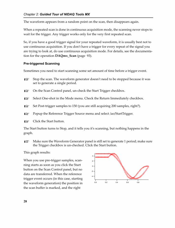
Make sure the Waveform Generator panel is still set to generate 1 period; make sure the Trigger checkbox is un-checked. Click the Start button.
This graph results:
-4
-2
0
2
4
0.80.60.40.20.0
When you use pre-trigger samples, scan-ning starts as soon as you click the Start button on the Scan Control panel, but no data are transferred. When the reference trigger event occurs (in this case, starting the waveform generation) the position in the scan buffer is marked, and the right
28

Chapter 2: Guided Tour of NIDAQ Tools MX
number of post-trigger samples is acquired, then scanning stops. Since this is less than the total number of samples to be scanned, some of the samples come from before the trigger event.
Note that you must wait long enough for all the pre-trigger samples to be acquired before applying the reference trigger event. If you don't wait long enough, nothing happens when you assert the trigger.
Also, note that the graph doesn't show you the acquired data until it is all acquired. The NI-DAQmx driver doesn't allow you to get scanned data before the task is finished when you are using pre-triggering.
Other Waveform Generation Notes
Checking External Timebase allows you to use some signal other than the usual wave-form generator timebase for timing the waveform updates. Each pulse of the timebase will cause the next sample to be output from the analog outputs. You might use the analog input sample clock in order to synchronize scanning and waveform generation. You might use a counter/timer to achieve other special effects. You might need to synchronize waveform generation to some external event like the rotation of a shaft.
If the waves used to generate output waveforms have values outside the full scale voltage range of the data acquisition device, the NI-DAQmx driver reports an error.
Continuous Analog Input into FIFOs
Putting analog input into waves is fine for some things, but sometimes you don't know ahead of time how much data you need to‘ acquire. Scanning into waves requires setting the size of the waves ahead of time. Acquiring an indefinite amount of data requires mak-ing waves bigger than the largest amount of data you think you might ever want, which can be either very large, or impossible to determine.
FIFOs (First-In, First-Out buffers) offer a means of acquiring data and streaming it onto disk, eliminating the need to know how much data you will acquire ahead of time, as long as you have enough disk space. To learn more about Igor FIFOs, see the topic FIFOs and Charts in the Advanced Topics help file, which you will find in the More Help Files folder in the Igor Pro folder on your hard disk.
This section will assume that you still have the analog inputs connected to the analog out-puts, as in the last section. This is not strictly necessary, but the results will be more inter-
29

Chapter 2: Guided Tour of NIDAQ Tools MX
esting. It is clearly impossible if you are using a simulated device. In that case your data will not look like the pictures shown here.
This section of the guided tour is best done from a clean slate, so pull down the File menu and select New Experiment (save the old one if you want).
Enter these lines in the Procedure window:
#include <NIDAQmxWaveFormGenProcs>#include <NIDAQmxFIFOProcs>
The first line you have seen before, in the previous section of this guided tour. The last brings in procedures to support data acquisition into IGOR FIFOs.
Click the Compile button and close the Procedure window.
The NIDAQ Tools MX menu now contains 'FIFO Scan' and ‘Review FIFO’ in addition to the Waveform Generator item that should be familiar from previous sections of the tour.
In the NIDAQ Tools MX menu select Waveform Generator to build the Waveform Generator Control panel. On the panel, select Make Demo Wave for both channels. The period should be 1 second.
Do not click the start button yet.
In the NIDAQ Tools MX menu select FIFO Scan to build the FIFO Scan Control panel.
This makes a control panel that looks like this:
The FIFO Scan Control panel builds and exe-cutes a command line that calls the operation DAQmx_Scan (page 93), the same operation used by the Scan Con-trol panel (Acquiring Analog Data into
30

Chapter 2: Guided Tour of NIDAQ Tools MX
Waves on page 15). But the FIFO Control panel uses the FIFO keyword instead of the WAVES keyword.
On the left side of the FIFO Control Panel is an area for setting various characteristics of the FIFO and data acquisition.
You are already familiar with the Sample Period setting from scanning into waves; it sets the time between successive samples on one channel.
Set the Sample Period to 0.01 and type Return or Enter.
Note that Sample Frequency changes to 100 when you change the period. You can also set the frequency and the period will change.
Verify that Convert Period is zero and Averaging Samples is 1. Start Trigger, Sam-ple Clock and Convert Clock should not be checked.
Verify that the FIFO Size is set to 10000.
A FIFO is a data structure with a large buffer to temporarily store data on its way to disk (or into a Chart control). The ‘FIFO Size’ setting controls the size of this buffer; the number tells how many “chunks” of data it holds. A chunk is a sample for every channel. It should be set to 10000 already, as that is the default value.
In the Channel Selector list box on the right, check the checkboxes in the Input Channel column for Channel 0 and Channel 1.
On the left of the channel selector is a column of check boxes that allow you to select which analog inputs will be sampled. The number of channels offered depends on the number of input channels available on your DAQ device.
For now, we will use the default channel names Chan0, Chan1, etc. Verify that “Chan0” is entered in the Channel Name column for the Channel 0 row, and “Chan1” for the Channel 1 row.
The channel selector list box is similar to the one used for scanning into waves. Instead of a column of text boxes and popup menus for selecting wave names, this panel has a col-umn of text boxes to set the names of channels in the IGOR FIFO.
You must provide a name for each FIFO channel. Click a cell in the Channel Name column to put it into edit mode and type the desired name. The channel names are initialized to “ChanN” where N is the channel number. You can make the channel names anything you
31

Chapter 2: Guided Tour of NIDAQ Tools MX
like, as long as they are standard IGOR names, not liberal names. See the Object Names section of the Using Igor help file for more information on Igor names.
Note: If you enter a channel name that is not a legal name, the offending characters will be replaced with an underscore. If the first character is not acceptable to IGOR, a “C” (for Channel) will be prepended to the name to make it legal. An alert box will make sure you know about the change. Note that FIFO channel names are not allowed to be “liberal”.
As you did with the Scan Control Panel(page 23), make sure the input mode matches the connections you have made between the analog inputs and the analog outputs.
To simplify the connections, we used RSE.
Set Min V and Max V to -10 and 10.
Click the Start/Chart tab.
This tab is mostly filled by a Chart control that will display the data as it is acquired.
Click the Start Scan button.
Horizontal lines march across the chart. The data are flat because there is no signal.
Click in the Waveform Generator panel, if it is showing, or select Waveform Gener-ator from the NIDAQ Tools MX menu to bring the Waveform Generator panel to the front.
Click the Start button.
Two wavy lines march across the chart, something like this:
32

Chapter 2: Guided Tour of NIDAQ Tools MX
Note: You can re-size this panel by dragging the lower-right corner of the panel. Re-sizing will change the size of the channel selection list box on the Scan Settings tab, the chart control on the Start/Chart tab, and the channel appearance list box on the Chart Appearance tab.
Now we'd like to have the acquired data written into a disk file.
Click the Stop Scan button.
Click the Scan Settings tab.
Enter ‘TestFile’ in the ‘FIFO file:’ box and click the Start/Chart tab.
Click the Start Scan button.
An Open File dialog appears giving you a chance to change the file name and select a folder for the FIFO file.
Select a place for your file and click the Save button.
Once again wavy lines march across the chart.
Turn the Waveform generator off and on a few times, so you can see something change. After 10 seconds or so, go back to the Chart panel and click the Stop Scan button.
You now have an IGOR FIFO file on your disk, called TestFile. In 10 seconds, the file will accumulate 16kb. Think what could happen in a few minutes or hours...
33

Chapter 2: Guided Tour of NIDAQ Tools MX
Reviewing a FIFO File
After you have stopped scanning (or even while scanning) you can drag the “paper” in the chart control in order to review data already recorded. You can also open a previously recorded FIFO file and review it in the Review FIFO File panel.
Select Review FIFO from the NIDAQ Tools MX menu.
Click the Select File... button below the chart. Select TestFile, the FIFO file you just created.
By default, the FIFO Scan control panel creates FIFO files with the filename extension “.bin” to indicate that it holds binary data. The Save as Type menu allows you to select “.dat” or “All files”. Selecting All Files allows you to enter any filename extension you wish.
Also by default, the FIFO Review control panel shows files with filename extension of “.bin”, and you can select “.dat” or “All Files” from the menu.
The chart shows you the contents of the file. It may be necessary to drag the “paper” in the chart control to the left in order to see the data.
The Chart tries to configure itself automatically for a “nice” horizontal scale, so it may not look precisely like it did when it was running. Mine looks like this after dragging the paper left:
Note: Everything in this section except for opening a FIFO file to review applies to the FIFO Scan panel as well.
You can change the horizontal scale of the chart display with the zoom buttons. Each time you press the In button, the horizontal display is expanded by a factor of two. The Out button compresses the horizontal scale by a factor of two. You
34
Chapter 2: Guided Tour of NIDAQ Tools MX
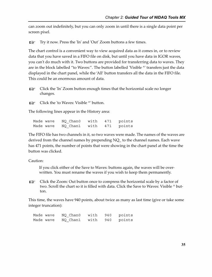
can zoom out indefinitely, but you can only zoom in until there is a single data point per screen pixel.
Try it now. Press the 'In' and 'Out' Zoom buttons a few times.
The chart control is a convenient way to view acquired data as it comes in, or to review data that you have saved in a FIFO file on disk, but until you have data in IGOR waves, you can't do much with it. Two buttons are provided for transferring data to waves. They are in the block labelled “to Waves:”. The button labelled 'Visible ^' transfers just the data displayed in the chart panel, while the ‘All’ button transfers all the data in the FIFO file. This could be an enormous amount of data.
Click the 'In' Zoom button enough times that the horizontal scale no longer changes.
Click the 'to Waves: Visible ^' button.
The following lines appear in the History area:
Made wave NQ_Chan0 with 471 points Made wave NQ_Chan1 with 471 points
The FIFO file has two channels in it, so two waves were made. The names of the waves are derived from the channel names by prepending NQ_ to the channel names. Each wave has 471 points, the number of points that were showing in the chart panel at the time the button was clicked.
Caution:
If you click either of the Save to Waves: buttons again, the waves will be over-written. You must rename the waves if you wish to keep them permanently.
Click the Zoom: Out button once to compress the horizontal scale by a factor of two. Scroll the chart so it is filled with data. Click the Save to Waves: Visible ^ but-ton.
This time, the waves have 940 points, about twice as many as last time (give or take some integer truncation):
Made wave NQ_Chan0 with 940 points Made wave NQ_Chan1 with 940 points
35

Chapter 2: Guided Tour of NIDAQ Tools MX
The exact numbers will depend on the zoom factor and the size of the panel (and therefore the chart) when you click the Visible ^ button.
The buttons don't provide as much resolution in saving the data to waves as you might like. If you transfer more data than you really wanted, you can use Duplicate and graph cursors to pick out just the data you want.
Changing the Chart Appearance
It is possible to change the appearance of the chart control in both the FIFO Scan panel and the FIFO Review panel.
Click the Chart Appearance tab.
This displays controls to alter the appearance of the chart. At the top is a list box for set-ting the display characteristics of individual channels:
Right-click to alter scaling from real data to chart display.
Edit to set relative vertical space allocated to each channel.
Right-click to set color.
Right-click to select display mode.
Channel name you set in the Channel Selector when the data were taken.
Un-check a row to hide it in the chart.
The Height column sets the relative vertical space occupied by each channel in the chart control. That is, setting one row to 2 and the others to 1 will give twice as much vertical space to that row. Setting all rows to 2 is the same as setting all rows to 1.
The controls in the lower part of the Chart Appearance tab affect the overall appearance of the chart control. Play around with them to see what they do...
36

Chapter 2: Guided Tour of NIDAQ Tools MX
One note worth mentioning: if you select Bare Bones from the Style menu, no status bar is displayed on the chart. In that case, the selections in the Status Bar menu have no effect on the chart appearance.
Counter/Timers
Included in the NIDAQ Tools MX package are three procedure files that implement two simple applications of the counter/timers that are included on most DAQ devices:
NIDAQmxPulseTrainGenerator.ipf Use a counter/timer to generate timed digi-tal pulses, or pulse trains; uses the operation DAQmx_CTR_OutputPulse (page 76).
NIDAQmxSimpleEventCounter.ipf Use a counter/timer to count digital pulses; uses the operation DAQmx_CTR_CountEdges (page 72).
NIDAQmxCounterUtilities.ipf Support for the other two procedure files.
The most likely use for these files is as a basis for your own programming. Use the files as an example of how to program the counter/timers. They implement simple control panels that may be useful as-is if your needs are simple.
In addition to pulse-train generation and event counting, the counter/timers on a DAQ device can be used to measure pulse width or pulse train frequency using the operations DAQmx_CTR_Period and DAQmx_CTR_PulseWidth (page 82).
Please look at the comments in the procedure files for information on how to use them.
Copying the Procedure Files
Feel free to use the procedure files we provide as the basis for your own programming.
If you want to customize the NIDAQ Tools MX procedure files, copy the entire NIDAQ Tools MX folder to a folder where you keep your own Igor procedures. Modify your copy, not the original procedures.
If you place a shortcut to your copy of the folder inside the User Procedures folder, you can use #include statements like this:
#include "myVersionNIDAQmxScanProcs"
37

Chapter 2: Guided Tour of NIDAQ Tools MX
Note the use of quote marks around the procedure file name, instead of angle brackets.
Programmer's TourThis section is intended as an introduction to the external operations and functions that are added to Igor Pro by NIDAQ Tools MX. It assumes that you have finished the NIDAQ Tools MX Guided Tour; if you have not, please do it now.
The procedure files summarized in the Guided Tour provide IGOR control panels for common data acquisition needs. They are constructed using external operations and func-tions added to IGOR by the NIDAQmx XOP. If the procedure files fill your needs, then you are ready to go. If the procedure files don't do everything you would like, you will need to do some IGOR programming.
This Programmer's Introduction is meant to give a quick overview of analog input and output using the NIDAQmx XOP by calling the external functions and operations your-self. Familiarity with IGOR programming is assumed. The material is not exhaustive. For complete details on all operations and functions, see NIDAQ Tools MX Reference on page 65.
Setup
You must install the NIDAQmx XOP and the NI-DAQmx driver. See Getting Ready on page 3 for details.
Finding the Device Name
Most NIDAQmx XOP functions and operations require that you specify the name assigned to the data acquisition device. The name is assigned by NI's Measurement and Automation Explorer (MAX). By default, these names are Dev1, Dev2, etc. You can change the name by editing in MAX. We chose to change the names to mnemonic names: MIO16 and PCI6229.
You can use the function fDAQmx_DeviceNames (page 113) to get a string containing a list of installed NI-DAQmx devices. Use standard Igor list-handling techniques to extract individual device names (see Using Strings as Lists in the Programming help file).
Use National Instruments' MAX application to set the device name to “dev1”.
38

Chapter 2: Guided Tour of NIDAQ Tools MX
The examples all use “dev1” as the device name. If your device uses that name, it will make it easier to follow the examples.
NIDAQ Tools MX Functions and Operations
NIDAQ Tools MX adds both functions and operations to Igor. A function takes a fixed set of input parameters and returns a value; an operation has complex syntax with flags or keywords to specify options. An operation does not return a result; if some output is required will be in the form of a variable created by the operaion. Operations are more flexible than functions, and NIDAQ Tools MX uses them for setting up major operations, like a scanning or waveform generation task. Functions are used to get single values or add more sophisticated control to a task. For instance, you might set up an event-counting task using the operation DAQmx_CTR_CountEdges (page 72). You would subsequently use the fDAQmx_CTR_ReadCounter (page 111) to get the current count.
Variables Created by NIDAQ Tools MX Operations
A few NIDAQ Tools MX operations create variables to transmit some output. For instance, the operation DAQmx_DIO_Config (page 87) creates the variable V_DAQmx_DIO_TaskNumber to return the task index to you.
If you enter an operation on the command line, these variables are global variables. You can find them in the Data Browser and they are saved when you save the experiment file.
If you call an operation from a user-defined function or macro, however, the variables are local. That is, they exist only while the calling function is running. If you will need the information in a variable later, you should save it, probably in a global variable. For instance, a trivial example:
Function MyDIOFunc()
DAQmx_DIO_Config/DEV="dev1" "/dev1/port0/line0"Variable/G DIOTaskIndex = V_DAQmx_DIO_TaskNumber
end
Function MyDIOReader()
NVAR DIOTaskIndexprint fDAQmx_DIO_Read("dev1", DIOTaskIndex)
end
39

Chapter 2: Guided Tour of NIDAQ Tools MX
IMPORTANT- Checking for Errors
Errors are inevitable in any real data acquisition system. It is critically important that you check for errors. Before calling for tech support, get an error message!
Getting a text error message
When an error occurs in the execution of a NIDAQ Tools MX function or operation, a descriptive message is available using the function fDAQmx_ErrorString (page 116). This function returns a string containing the error message text. One way to use the string is to simply use the Print operation to display the message in the history area.
When an error occurs, the error is stored internally by NIDAQ Tools MX. You retrieve the error information using fDAQmx_ErrorString (page 116); this function also erases the error information that was stored.
Up to five errors are kept in storage, so you don’t necessarily have to retrieve the informa-tion immediately. If more than one error has occurred, you can get the error information for all stored errors by calling fDAQmx_ErrorString repeatedly. The first time you call the function, you get the most recent error information; subsequent calls get the next old-est message, working backwards in time. If there are no further messages, fDAQmx_ErrorString returns an empty string.
There are two types of errors- errors detected by NIDAQ Tools MX, and errors detected by the NI-DAQmx driver. Errors detected by NIDAQ Tools MX have error numbers greater than 10000 and short error messages.
Errors detected by the NI-DAQmx driver usually have error numbers more negative than -200000. The message text returned by fDAQmx_ErrorString includes the name of the NIDAQ Tools MX operation or function that was executing, the name of the NI-DAQmx function that returned the error, and an often very long description of the error. NIDAQ Tools MX gets this text description of the error from the NI-DAQmx driver by calling the function DAQmxGetExtendedErrorInfo. In our experience, these messages can be very helpful, but they are so long you may not want to print them into the history area.
Errors During Execution of NIDAQ Tools MX Operations
NIDAQ Tools MX operations return error codes to Igor when something goes wrong. If the operation was called from a user-defined function, execution of the function is termi-nated and an alert is displayed.
40

Chapter 2: Guided Tour of NIDAQ Tools MX
It may be preferable for your code to continue running so that it can take some recovery action. To do that, your code must intercept the error. There are two ways to do that; both methods use the GetRTError function. This function can be used to get the error number from Igor and optionally prevent your running code from being aborted.
Method 1: Just use GetRTError.
The following Igor user-defined function tries to start a scanning operation but the device name is bad. It catches the error using GetRTError and prints error information in the his-tory window:
Function MyScanFunction()
DAQmx_Scan/DEV="nonexistentDevice" ...if (GetRTError(1)) // 1 to clear error and continue execution
print "Error starting scanning operation"print fDAQmx_ErrorString()
endifend
You could use the if block to try to recover from the error and continue.
This style of error handling requires that every NIDAQ Tools MX operation be followed by an if statement with a call to GetRTError.
Method 2: Use try-catch-endtry.
You can enclose a block of code in a try-catch block to intercept errors. This allows you to put error handling code in a block at the end of the code that does the work:
Function MyScanFunction()
Variable errorCodetry
DAQmx_Scan/DEV="nonexistentDevice" ...;AbortOnRTEerrorCode = fDAQmx_ScanWait("device");AbortOnValue errorcode!=0, 1
catchif (V_AbortCode == -4)
print "Error starting scanning operation"Variable dummy=GetRTError(1) // to clear the error condition
elseif (V_AbortCode == 1)print "Error executing fDAQmx_ScanWait"
endif
41

Chapter 2: Guided Tour of NIDAQ Tools MX
print fDAQmx_ErrorString()endtry
end
The procedure files included with NIDAQ Tools MX use the try-catch-endtry method.
Errors During Execution of NIDAQ Tools MX Functions
NIDAQ Tools MX functions do not terminate execution, so it is doubly important to check return values for error codes. If you do not, subsequent operations are likely to fail, and you won't know what caused it.
All NIDAQ Tools MX functions return a value- for some, like fDAQmx_ReadChan (page 118), the return value is the result you are interested in. In this case NIDAQ Tools MX returns NaN (Not a Number) to signal that an error occurred. To check for this, use Igor’s built-in numtype function.
In other cases, the return value of the function is not used for anything else, so it signals success by returning zero, and failure by returning non-zero.
Here is an example that shows how to check functions for errors signalled by returning NaN:
Function ReadAChan()
Variable AnalogInputValueAnalogInputValue = fDAQmx_ReadChan("dev1", 0, -10, 10, 0)if (numtype(AnalogInputValue) != 0)
print "Error reading analog input"print fDAQmx_ErrorString()
endifend
And this one checks for errors from a function that returns non-zero for an error condi-tion:
Function DoScan()
// for the example, assume this works:DAQmx_Scan/DEV="dev1" ...... do some stuff ...if (fDAQmx_ScanWait("dev1"))
print "Error executing fDAQmx_ScanWait"
42

Chapter 2: Guided Tour of NIDAQ Tools MX
print "fDAQmx_ErrorString()endif
end
The example in the previous section, Errors During Execution of NIDAQ Tools MX Functions on page 42, shows how you can use try-catch-endtry with AbortOnValue to handle function errors.
Analog Input
The NIDAQmx XOP provides operations to support automatic sampling of multiple ana-log input channels. These functions can transfer data to waves or FIFOs. Acquisition into waves allows immediate access to IGOR's analysis and graphing capabilities but requires that you create the waves ahead of time, thereby fixing the maximum amount of data that can be collected. FIFOs (First-In, First-Out) provide a mechanism for acquiring an indeter-minate amount of data, and storing data on disk as it is acquired. IGOR provides mecha-nisms for reviewing the data and selecting sections to be saved in waves for processing and graphing.
For lists of functions and operations supporting analog input, see Analog Input on page 65.
Analog Input Using Waves
NIDAQ Tools MX provides several variations on collecting analog input data into Igor waves. The examples that follow are best done with the analog outputs connected to the analog inputs.
Connect the analog outputs to the analog inputs.
Do this as described on page 23.
Make sure you have the Waveform Generator available and running.
The best way to do the examples in this section is with the Waveform Generator running, and with the analog outputs AO0 and AO1 connected to the analog inputs AI0 and AI1. See Generating Waveforms from the Analog Outputs on page 22 if you need help with this.
Execute these lines to create waves suitable for scanning the analog inputs:
Make/O/N=100 Wave0, Wave1 // /O overwrites existing waves
43

Chapter 2: Guided Tour of NIDAQ Tools MX
SetScale/P x, 0,0.1, "s", Wave0, Wave1
When the data are read into waves, the sampling rate and number of samples to collect are controlled by the waves you provide to receive the data. The number of samples to collect is set by the number of data points in the waves and the sampling rate is set by the wave scaling. The commands above create waves with 100 points and with wave scaling having delta X set to 0.1. When these waves are used for analog input scanning, 100 data points will be acquired at intervals of 0.1 second, resulting in scanning over a period of 10 seconds.
The X units in this example are set to “s” for seconds, but the units setting is not used by the XOP.
If you aren’t familiar with wave scaling, see the Waves chapter of the Igor User’s Guide, Part I.
Execute the following command:
DAQmx_Scan/DEV="dev1" WAVES="Wave0, 0; Wave1, 1;"
The WAVES keyword tells DAQmx_Scan that you wish to acquire the data into waves. The string following the WAVES keyword is the parameter string.
The input connection mode is not specified in the command; it defaults to something appropriate to the DAQ device. That means differential for most devices, referenced sin-gle-ended for some, and pseudo-differential for S-series devices. The appropriate connec-tions to make between the analog outputs and the analog inputs will depend on the DAQ device.
The parameter string lists wave name/channel number pairs. Each pair has a wave name first, a comma, then a channel number. The pairs are separated by semicolons.
To scan multiple channels, you must provide multiple waves. All the waves must have the same number of points. The sample rate is taken from the X scaling of the first wave in the list. Making the waves together as in the commands above guarantees that these require-ments are met.
The beach ball spun for 10 seconds while you read all that text. If you made a mistake entering the commands, an alert box told you that.
44

Chapter 2: Guided Tour of NIDAQ Tools MX
Simply having the data is nice, but you probably won't be satisfied until you've done something with it.
Make a graph of the data by executing this line:
Display Wave0, Wave1
The result should be a graph something like this:
-4
-2
0
2
4
86420s
While DAQmx_Scan was executing, the beach ball spun and you just cooled your heels waiting for the data. Fortunately, it took only ten seconds.
Execute this command:
DAQmx_Scan/DEV="dev1"/BKG WAVES="Wave0, 0; Wave1, 1;"
If you use the /BKG flag with DAQmx_Scan, the XOP will acquire data in the background while you and IGOR do other things in the foreground. The data will be transferred to the waves as it is acquired.
This command acquires data into the same two waves used in the previous example, but the waves update as the data are acquired. If the graph is showing, you can see it change as new data is acquired.
You may want to optimize the graph update. The usual graph update mode does a variety of checking as it updates, including autoscaling. This is time-consuming, so IGOR Pro provides “live mode”, which dispenses with much of the checking, especially autoscaling, in order to increase the update speed. Because live mode disables autoscaling, you will want to set the vertical axis to a sensible range. The demo waveforms created by the Waveform Generator panel range from -4.9 to +4.9 V, so a range of +-5 makes sense.
Set your graph to Live mode and disable autoscaling of the vertical axis. Click in the graph to make it the target window, then execute these lines:
ModifyGraph live=1SetAxis left -5,5 // -5 to 5 is best for the WaveMetrics setup
Live mode doesn't make a great deal of difference to the example shown above, because the sampling rate is quite slow.
45
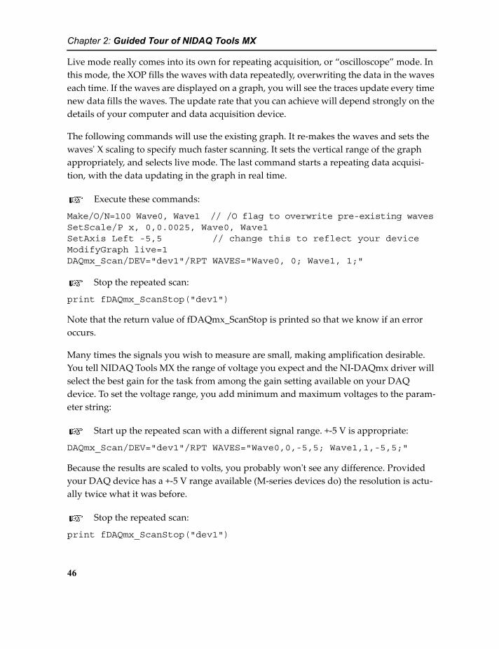
Chapter 2: Guided Tour of NIDAQ Tools MX
Live mode really comes into its own for repeating acquisition, or “oscilloscope” mode. In this mode, the XOP fills the waves with data repeatedly, overwriting the data in the waves each time. If the waves are displayed on a graph, you will see the traces update every time new data fills the waves. The update rate that you can achieve will depend strongly on the details of your computer and data acquisition device.
The following commands will use the existing graph. It re-makes the waves and sets the waves' X scaling to specify much faster scanning. It sets the vertical range of the graph appropriately, and selects live mode. The last command starts a repeating data acquisi-tion, with the data updating in the graph in real time.
Execute these commands:
Make/O/N=100 Wave0, Wave1 // /O flag to overwrite pre-existing wavesSetScale/P x, 0,0.0025, Wave0, Wave1SetAxis Left -5,5 // change this to reflect your deviceModifyGraph live=1DAQmx_Scan/DEV="dev1"/RPT WAVES="Wave0, 0; Wave1, 1;"
Stop the repeated scan:
print fDAQmx_ScanStop("dev1")
Note that the return value of fDAQmx_ScanStop is printed so that we know if an error occurs.
Many times the signals you wish to measure are small, making amplification desirable. You tell NIDAQ Tools MX the range of voltage you expect and the NI-DAQmx driver will select the best gain for the task from among the gain setting available on your DAQ device. To set the voltage range, you add minimum and maximum voltages to the param-eter string:
Start up the repeated scan with a different signal range. +-5 V is appropriate:
DAQmx_Scan/DEV="dev1"/RPT WAVES="Wave0,0,-5,5; Wave1,1,-5,5;"
Because the results are scaled to volts, you probably won't see any difference. Provided your DAQ device has a +-5 V range available (M-series devices do) the resolution is actu-ally twice what it was before.
Stop the repeated scan:
print fDAQmx_ScanStop("dev1")
46

Chapter 2: Guided Tour of NIDAQ Tools MX
Note: The /RPT flag selects repeated scanning. Use the /RPTC flag to get the same effect as the Use Continuous Acquisition checkbox on the Scan Control panel discussed previously (page 26).
Waves for Analog Input Scanning
Wave Scaling
Setting the wave X scaling is important when using NIDAQ Tools MX for acquiring data into waves, because it sets the sampling rate. The wave scaling is set by the SetScale oper-ation as follows:
SetScale/P x, X0, dX, "s", waveName
This will set the scaling to start at X0, and increment by dX per point. The /P option selects the “per point” mode in which the two numeric arguments are X0 and dX. The “s” sets the units string for the wave. Here it is set to “s” for seconds, but the XOP does not check the units and they can be omitted.
To make a wave with 100 points and X scaling of 0.1 per point you would execute com-mands like these:
Make/O/N=100 Wave0 // /O flag to overwrite pre-existing wavesSetScale/P x, 0,0.1,Wave0
The only part of the wave scaling that is used by the NIDAQmx XOP is dX, which sets the sample period. In a list of waves to be used for multi-channel scanning, the XOP takes the sample period from the dX parameter of the first wave in the list. The XOP will set dX for the rest of the waves to match the first.
The sample period set by the wave scaling is the rate for each channel. If you scan multi-ple channels, the actual conversion rate is the sample rate times the number of channels. For instance, you may expect the data acquisition device and your computer to be able to acquire data at, say, 200,000 samples per second. If you ask for 4 channels at 100,000 sam-ples per second, the required conversion rate is 400,000 samples per second. The hypo-thetical DAQ device cannot do this.
The NIDAQmx XOP will make two adjustments to the wave scaling. First, because the onboard sample clock has finite resolution, the NI-DAQmx driver selects the sample rate closest to the rate requested by the wave scaling. NIDAQ Tools MX queries the driver to get the actual rate that was achieved and adjusts the wave scaling accordingly. NIDAQ Tools MX then uses this (only slightly) adjusted value to set dX for the waves.
47

Chapter 2: Guided Tour of NIDAQ Tools MX
When scanning multiple channels, most data acquisition devices sample the channels sequentially rather than simultaneously. In setting up data acquisition, NIDAQ Tools MX ignores the X0 (offset) scaling factor. However, it sets X0 to reflect the time offset between channels.
If you are using an S-series DAQ device, X0 is always set to zero because these devices sample all channels simultaneously.
Note that if an external clock is used, NIDAQ Tools MX has no idea how fast the channels are being scanned. In this case, the wave scaling is ignored and no adjustments are made to the scaling. You must be sure to set the wave scaling yourself.
Number Type
The number type of a wave is set by flags used with the Make operation. The waves for scanning can have any number type except 8-bit integer or text. If your wave is a floating point type (Make/D or Make with no type flag) then the data returned is scaled to volts.
If you use an integer type (Make/I or Make/W possibly with the /U flag for unsigned) you get raw integer values. For a 12-bit device, that means numbers from -2048 to 2047 for signed data; for 16-bit devices, -32768 to 32767. You must take care of any conversion yourself. Note that if you use unsigned integer waves and your data includes negative numbers, you will see strange results.
You cannot mix waves having different number types in a single scanning operation.
The performance will be best with double-precision (Make/D) or 16-bit integer (Make/W) waves.
Scanning order
The channels are scanned in the order in which they appear in the parameter list.
Note that you can simulate a higher sampling rate on one channel by including it in the list more than once.
Analog Input Using FIFOs
An IGOR FIFO is a data structure designed to accommodate data acquisition over an indefinite time. It consists of a block of memory and an optional connection to a file on disk. The block of memory is used as a ring buffer- new data is added to the buffer
48

Chapter 2: Guided Tour of NIDAQ Tools MX
sequentially until it is filled. After the buffer is filled, the oldest data is overwritten. If the FIFO is attached to a disk file, IGOR does its best to move the data out of the buffer to the disk file before it is overwritten. IGOR will also optionally display the data in the FIFO in a Chart control, also in real time. Data transfers to the FIFO and Chart controls are done during background processing, allowing IGOR to do other things while the data are com-ing in.
Unlike waves, FIFOs contain multiple channels in one IGOR object. The NIDAQmx XOP can transfer data into 16- or 32-bit integer FIFO channels, as well as single- or double-pre-cision floating point channels. It will not accept complex or 8-bit channels.
Integer channels should be faster than floating point because the raw data is simply trans-ferred to the FIFO, whereas the data is converted to floating point and scaled to Volts when a floating point channel is used. On modern computers, the performance will prob-ably be limited by the data acquisition device and using an integer FIFO will be a waste of time.
To use FIFOs for data acquisition, several steps must be completed:
1) Make a FIFO (NewFIFO operation)
2) Add desired number of channels to the FIFO (NewFIFOChan operation, repeated as many times as you need)
3) Set the deltaT for the FIFO in order to set the sampling rate (CtrlFIFO operation)
4) If you wish to connect the FIFO to a disk file:
4a)Open a disk file (Open operation)
4b)Attach the file to the FIFO (CtrlFIFO operation)
5) If you want to display the acquired data in a chart control:
5a)Make a control panel or graph to hold the chart control (Display or NewPanel operation)
5b)Make a chart control in the panel or graph (Chart operation)
5c) Attach the FIFO to the chart control (Chart operation)
6) Before starting data acquisition, start the FIFO (CtrlFIFO operation)
7) Finally, start data acquisition (DAQmx_Scan operation).
49
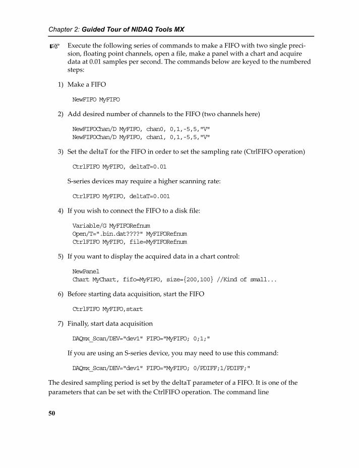
Chapter 2: Guided Tour of NIDAQ Tools MX
Execute the following series of commands to make a FIFO with two single preci-sion, floating point channels, open a file, make a panel with a chart and acquire data at 0.01 samples per second. The commands below are keyed to the numbered steps:
1) Make a FIFO
NewFIFO MyFIFO
2) Add desired number of channels to the FIFO (two channels here)
NewFIFOChan/D MyFIFO, chan0, 0,1,-5,5,"V"NewFIFOChan/D MyFIFO, chan1, 0,1,-5,5,"V"
3) Set the deltaT for the FIFO in order to set the sampling rate (CtrlFIFO operation)
CtrlFIFO MyFIFO, deltaT=0.01
S-series devices may require a higher scanning rate:
CtrlFIFO MyFIFO, deltaT=0.001
4) If you wish to connect the FIFO to a disk file:
Variable/G MyFIFORefnumOpen/T=".bin.dat????" MyFIFORefnumCtrlFIFO MyFIFO, file=MyFIFORefnum
5) If you want to display the acquired data in a chart control:
NewPanelChart MyChart, fifo=MyFIFO, size={200,100} //Kind of small...
6) Before starting data acquisition, start the FIFO
CtrlFIFO MyFIFO,start
7) Finally, start data acquisition
DAQmx_Scan/DEV="dev1" FIFO="MyFIFO; 0;1;"
If you are using an S-series device, you may need to use this command:
DAQmx_Scan/DEV="dev1" FIFO="MyFIFO; 0/PDIFF;1/PDIFF;"
The desired sampling period is set by the deltaT parameter of a FIFO. It is one of the parameters that can be set with the CtrlFIFO operation. The command line
50
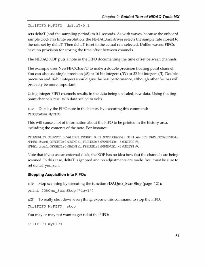
Chapter 2: Guided Tour of NIDAQ Tools MX
CtrlFIFO MyFIFO, deltaT=0.1
sets deltaT (and the sampling period) to 0.1 seconds. As with waves, because the onboard sample clock has finite resolution, the NI-DAQmx driver selects the sample rate closest to the rate set by deltaT. Then deltaT is set to the actual rate selected. Unlike waves, FIFOs have no provision for storing the time offset between channels.
The NIDAQ XOP puts a note in the FIFO documenting the time offset between channels.
The example uses NewFIFOChan/D to make a double precision floating point channel. You can also use single precision (/S) or 16-bit integers (/W) or 32-bit integers (/I). Double-precision and 16-bit integers should give the best performance, although other factors will probably be more important.
Using integer FIFO channels results in the data being unscaled, raw data. Using floating-point channels results in data scaled to volts.
Display the FIFO note in the history by executing this command:FIFOStatus MyFIFO
This will cause a lot of information about the FIFO to be printed in the history area, including the contents of the note. For instance:
FILENUM:37;DISKTOT:0;VALID:1;DELTAT:0.01;NOTE:Channel dt=1.4e-005;DATE:3202895054;NAME0:chan0;OFFSET0:0;GAIN0:1;FSPLUS0:5;FSMINUS0:-5;UNITS0:V;NAME1:chan1;OFFSET1:0;GAIN1:1;FSPLUS1:5;FSMINUS1:-5;UNITS1:V;
Note that if you use an external clock, the XOP has no idea how fast the channels are being scanned. In this case, deltaT is ignored and no adjustments are made. You must be sure to set deltaT yourself.
Stopping Acquisition into FIFOs
Stop scanning by executing the function fDAQmx_ScanStop (page 121):
print fDAQmx_ScanStop("dev1")
To really shut down everything, execute this command to stop the FIFO:
CtrlFIFO MyFIFO, stop
You may or may not want to get rid of the FIFO:
KillFIFO myFIFO
51

Chapter 2: Guided Tour of NIDAQ Tools MX
Gain
As with scanning into waves, by default the voltage range is set to -10 to 10 Volts. To get better resolution on smaller signals, you can set a different range. For instance, to set a range of +-5 Volts, do this:
DAQmx_Scan/DEV="dev1" FIFO="MyFIFO; 0,-5,5;1,-5,5;"
In this case, the range for both channels has been set to +-5. Each channel can have a differ-ent range if you wish. The NI-DAQmx driver uses your range specification to choose the best gain setting available on your DAQ device.
Numeric Type
If you make FIFO channels with a floating-point numeric type (NewFIFOChan/S or NewFIFOChan/D), the data are scaled to volts before being stored in the FIFO. If you use an integer type (NewFIFOChan/W or NewFIFOChan/I) you get raw, unscaled data. On a DAQ device with 16-bit resolution, the values would range between -32768 and +32767.
FIFO gain
If you are using an integer numeric type, the gain parameter of the FIFO can be set to con-vert integer FIFO data to Volts. You must figure out the scaling factor appropriate to your device and the particular scanning operation. That also means you need to figure out what gain will be used for the voltage range you specify.
The FIFO channel gain is set when you add a new channel to the FIFO using the newFIFO-chan operation. If you are using a device with 12-bit resolution set to 1-volt range, and you wish to use integer data in your FIFO, you would make the new channel with this command:
NewFIFOChan/S MyFIFO, chan0, 0,0.000244,-0.5,0.5,"V"
This command makes a new channel in the FIFO called MyFIFO, gives the channel the name “chan0”, sets the offset to zero, the gain to 0.000244, sets the range to –0.5 to 0.5, and the units to “V” for volts. The range setting is used by chart controls for setting the display range. The value 0.000244 is the voltage associated with a one-bit change in the output of the analog-to-digital converter. It was calculated like this:
Print (0.5 - -0.5) / 4096
52
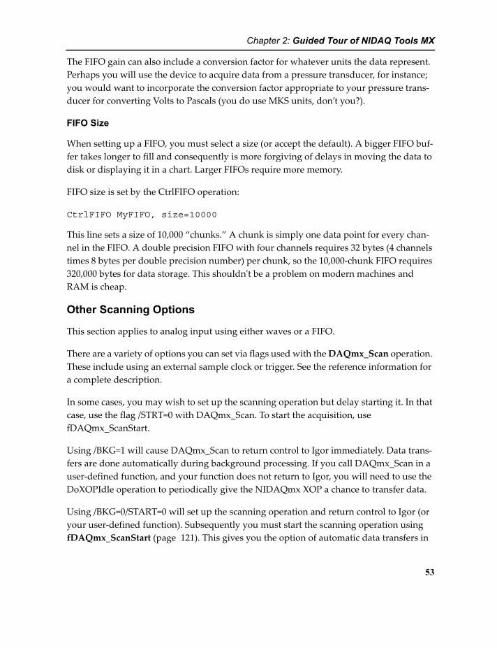
Chapter 2: Guided Tour of NIDAQ Tools MX
The FIFO gain can also include a conversion factor for whatever units the data represent. Perhaps you will use the device to acquire data from a pressure transducer, for instance; you would want to incorporate the conversion factor appropriate to your pressure trans-ducer for converting Volts to Pascals (you do use MKS units, don’t you?).
FIFO Size
When setting up a FIFO, you must select a size (or accept the default). A bigger FIFO buf-fer takes longer to fill and consequently is more forgiving of delays in moving the data to disk or displaying it in a chart. Larger FIFOs require more memory.
FIFO size is set by the CtrlFIFO operation:
CtrlFIFO MyFIFO, size=10000
This line sets a size of 10,000 “chunks.” A chunk is simply one data point for every chan-nel in the FIFO. A double precision FIFO with four channels requires 32 bytes (4 channels times 8 bytes per double precision number) per chunk, so the 10,000-chunk FIFO requires 320,000 bytes for data storage. This shouldn't be a problem on modern machines and RAM is cheap.
Other Scanning Options
This section applies to analog input using either waves or a FIFO.
There are a variety of options you can set via flags used with the DAQmx_Scan operation. These include using an external sample clock or trigger. See the reference information for a complete description.
In some cases, you may wish to set up the scanning operation but delay starting it. In that case, use the flag /STRT=0 with DAQmx_Scan. To start the acquisition, use fDAQmx_ScanStart.
Using /BKG=1 will cause DAQmx_Scan to return control to Igor immediately. Data trans-fers are done automatically during background processing. If you call DAQmx_Scan in a user-defined function, and your function does not return to Igor, you will need to use the DoXOPIdle operation to periodically give the NIDAQmx XOP a chance to transfer data.
Using /BKG=0/START=0 will set up the scanning operation and return control to Igor (or your user-defined function). Subsequently you must start the scanning operation using fDAQmx_ScanStart (page 121). This gives you the option of automatic data transfers in
53
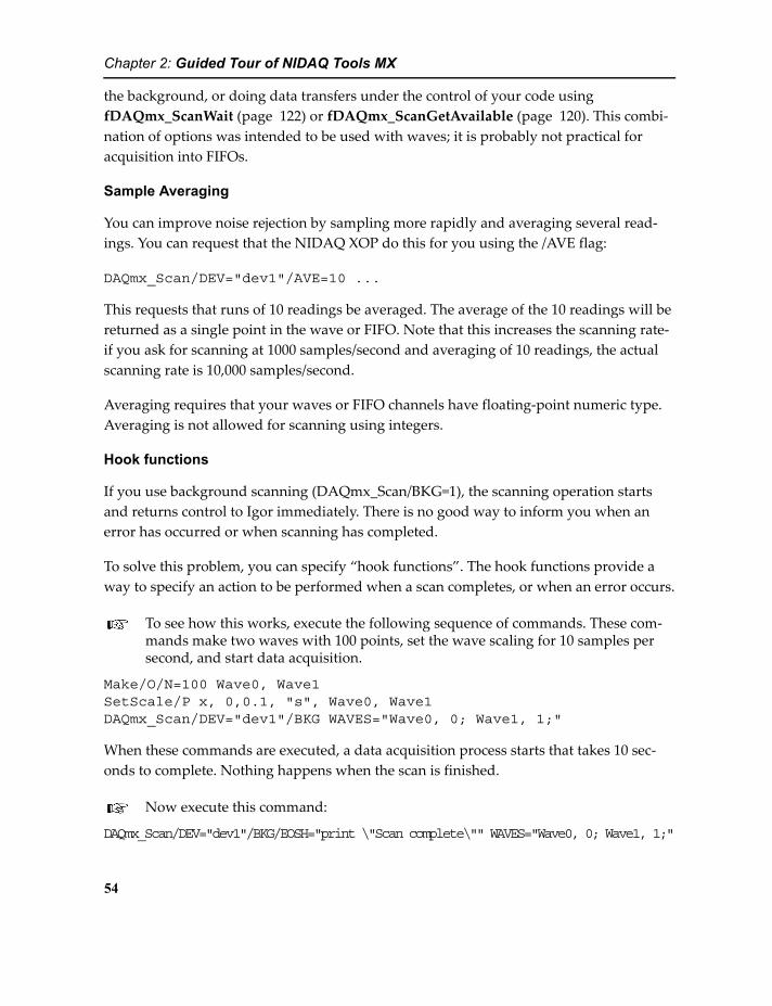
Chapter 2: Guided Tour of NIDAQ Tools MX
the background, or doing data transfers under the control of your code using fDAQmx_ScanWait (page 122) or fDAQmx_ScanGetAvailable (page 120). This combi-nation of options was intended to be used with waves; it is probably not practical for acquisition into FIFOs.
Sample Averaging
You can improve noise rejection by sampling more rapidly and averaging several read-ings. You can request that the NIDAQ XOP do this for you using the /AVE flag:
DAQmx_Scan/DEV="dev1"/AVE=10 ...
This requests that runs of 10 readings be averaged. The average of the 10 readings will be returned as a single point in the wave or FIFO. Note that this increases the scanning rate- if you ask for scanning at 1000 samples/second and averaging of 10 readings, the actual scanning rate is 10,000 samples/second.
Averaging requires that your waves or FIFO channels have floating-point numeric type. Averaging is not allowed for scanning using integers.
Hook functions
If you use background scanning (DAQmx_Scan/BKG=1), the scanning operation starts and returns control to Igor immediately. There is no good way to inform you when an error has occurred or when scanning has completed.
To solve this problem, you can specify “hook functions”. The hook functions provide a way to specify an action to be performed when a scan completes, or when an error occurs.
To see how this works, execute the following sequence of commands. These com-mands make two waves with 100 points, set the wave scaling for 10 samples per second, and start data acquisition.
Make/O/N=100 Wave0, Wave1SetScale/P x, 0,0.1, "s", Wave0, Wave1DAQmx_Scan/DEV="dev1"/BKG WAVES="Wave0, 0; Wave1, 1;"
When these commands are executed, a data acquisition process starts that takes 10 sec-onds to complete. Nothing happens when the scan is finished.
Now execute this command:
DAQmx_Scan/DEV="dev1"/BKG/EOSH="print \"Scan complete\"" WAVES="Wave0, 0; Wave1, 1;"
54

Chapter 2: Guided Tour of NIDAQ Tools MX
The same thing happens again, but this time, “Scan complete” is printed in the history area when the scanning operation is finished. Any command that can be executed on the command line can be put in the hook function strings, as long as the total command line is not too long.
In most cases, you should write a user function to use as the hook function. A user-defined function allows much more flexibility in what can be accomplished by the hook function.
Here is an over-simplified example of the use of a user function as a hook function.
Copy this function and paste it into the Procedure window:Function myScanCompleteHook()
print "Scan Complete"end
Execute this line:DAQmx_Scan/DEV="dev1"/BKG/EOSH="myScanCompleteHook()" WAVES="Wave0, 0; Wave1, 1;"
The hook function command line this time is simply a command to call the user function.
In this trivial example, the user function does just what the command did in the first example. A real-life case would do something more useful, like initiating some analysis or re-starting the scan into different waves.
The DAQmx_Scan operation has two flags for hook functions- a hook for the completion of the scanning operation (/EOSH), and a hook for an error during the scanning operation (/ERRH).
For a real-life example of the use of hook functions, look at the code in the NIDAQmxWaveScanProcs.ipf procedure file. The hook functions are used to make the Stop button on the Scan Control panel back into a Start button, and to turn off the status box on the control panel.
In the NIDAQmxRepeatedScanProcs.ipf, the /EOSH hook is used to re-start scanning into the next set of waves.
Note: Remember that you may have no control over the current data folder at the time the hook function executes. You will need to be careful with references to global variables and waves.
55

Chapter 2: Guided Tour of NIDAQ Tools MX
Analog Output: Arbitrary Waveform Generation
Most of the data acquisition devices supported by the NIDAQ Tools MX have two or more analog output channels that can be used as arbitrary waveform generators. A series of val-ues sent to the analog outputs results in a time-varying output voltage. If the values are carefully chosen, you can generate any voltage waveform you want.
The operation DAQmx_WaveformGen (page 103) provides access to this arbitrary wave-form generator capability.
DAQmx_WaveformGen uses waves to set the values and timing of the output voltages. You supply a wave for each channel with the wave's X scaling set to give the appropriate update rate. The Y values stored in the wave represent voltages, and must be within the range allowed by your DAQ device. By default, the waveform will repeat endlessly until you stop it by calling fDAQmx_WaveformStop (page 124).
Prepare to display generated waveforms in the FIFO Scan Control Panel. If you don't remember how to do this, see Continuous Analog Input into FIFOs on page 29.
Make sure that the waveform generator outputs are connected to analog inputs for channels 0 and 1.
In the FIFO Scan control panel, set the sample period to 0.001 and select channels 0 and 1.
Start a FIFO scanning operation by selecting the Start/Chart tab and clicking the Start Scan button.
This will allow you to see the results of the examples to come.
Execute the following set of commands to make two waves, prepare them for waveform generation, and start the waveform generator:
Make/O/N=100 Waveform0, Waveform1SetScale x, 0, 1.0, "s", Waveform0, Waveform1Waveform0 = 4*sin(2*pi*x)Waveform1 = 4*cos(2*pi*x)DAQmx_WaveformGen/DEV="dev1" "Waveform0, 0; Waveform1,1;"
The SetScale command sets the scaling of the waves such that the waveform will have a period of 1 second. The two wave assignment statements put one cycle of a sinusoid in
56
Chapter 2: Guided Tour of NIDAQ Tools MX
each of the waves. The DAQmx_WaveformGen operation then starts the waveform gen-erator.
The form of the SetScale command used here sets X0 and “right X”. Since X0 is set to zero, the right X value (1.0) is the period of the waveform that will be produced.
Stop the waveform generator:
print fDAQmx_WaveformStop("dev1")
The wavy lines on the FIFO Scan Control panel go flat.
You can request just one or a specified number of periods of the waveforms using the /NPRD flag.
Execute the following command. It will generate just one period- watch the chart carefully:
DAQmx_WaveformGen/DEV="dev1"/NPRD=1 "Waveform0, 0; Waveform1,1;"
The following command will generate 5 periods:
DAQmx_WaveformGen/DEV="dev1"/NPRD=5 "Waveform0, 0; Waveform1,1;"
When you ask NI-DAQmx to generate a finite number of periods greater than 1, it uses one of the counter/timers on your DAQ device to count the periods generated. Conse-quently, that counter/timer will not be available for your own uses.
Stop the waveform generator:
print fDAQmx_WaveformStop("dev1")
Stop the scanning operation by clicking Stop Scan on the FIFO Scan Control panel.
Synchronizing Scanning with Waveform Generation
You can use internal signals as triggers to start a scanning operation at the same time as a waveform generation. You might do this to stimulate a neuron and scan the response to the stimulus.
For this example, we will do a background scanning operation with a graph so that you can see what happens as it happens. The commands will start a triggered scanning opera-tion that uses the analog output start signal as its trigger.
Start with a new experiment. Select New Experiment from the File menu.
57

Chapter 2: Guided Tour of NIDAQ Tools MX
Make the waves and graph for the scanning operation:
Make/O/N=500 Wave0, Wave // /O flag to overwrite pre-existing wavesSetScale/P x, 0,0.01, Wave0, Wave1Display Wave0, Wave1SetAxis Left -5,5 // change this to reflect your deviceModifyGraph live=1
The wave scaling and number of points is set to take five seconds of data.
Start the scanning operation:DAQmx_Scan/DEV="dev1"/TRIG={"/dev1/ao/starttrigger"}/BKG WAVES="Wave0,0; Wave1,1;"
Note that if your DAQ device is not called “dev1” you will have to change “dev1” in two places, one for the device to use for the scanning operation, and one in the path that defines the trigger signal.
This will not do anything because it is waiting for a trigger signal.
Start the waveform generator:
Make/O/N=100 Waveform0, Waveform1SetScale x, 0, 1.0, "s", Waveform0, Waveform1Waveform0 = 4*sin(2*pi*x)Waveform1 = 4*cos(2*pi*x)DAQmx_WaveformGen/DEV="dev1"/NPRD=1 "Waveform0, 0; Waveform1,1;"
Now the graph starts showing you new data.
Start the scan again:DAQmx_Scan/DEV="dev1"/TRIG={"/dev1/ao/starttrigger"}/BKG WAVES="Wave0,0; Wave1,1;"
Start the waveform generator again:
DAQmx_WaveformGen/DEV="dev1"/NPRD=1 "Waveform0, 0; Waveform1,1;"
The graph probably didn't change much, if at all. That's because the scan was synchro-nized to the waveform, causing the new data to be nearly identical to the old data.
You can also acquire data taken before the trigger signal occurred. To do that, you must specify a reference trigger using the /RTRG flag.
Start the scanning operation:
DAQmx_Scan/DEV="dev1"/RTRG={"/dev1/ao/starttrigger", 100}/BKG
58
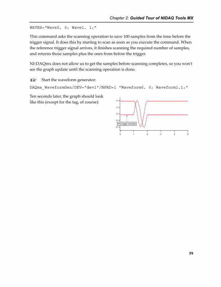
Chapter 2: Guided Tour of NIDAQ Tools MX
WAVES="Wave0, 0; Wave1, 1;"
This command asks the scanning operation to save 100 samples from the time before the trigger signal. It does this by starting to scan as soon as you execute the command. When the reference trigger signal arrives, it finishes scanning the required number of samples, and returns those samples plus the ones from before the trigger.
NI-DAQmx does not allow us to get the samples before scanning completes, so you won't see the graph update until the scanning operation is done.
Start the waveform generator:
DAQmx_WaveformGen/DEV="dev1"/NPRD=1 "Waveform0, 0; Waveform1,1;"
Ten seconds later, the graph should look like this (except for the tag, of course):
-4
-2
0
2
4
543210
Pre-trigger samples
59

Chapter 2: Guided Tour of NIDAQ Tools MX
60
3
NIDAQ Tools MX Technical Issues
Chapter 3
3NIDAQ Tools MX Technical IssuesSignal NamesMany of the functions and operations require the name of a “signal”. A signal is a source of a pulse or other, well, signal, that can be used as a trigger, clock, etc. These signal names have the form of a path- they start with a device name, may include a subsystem name (like ai for analog input) and conclude with a signal name (like starttrigger). So a complete path for specifying the analog input start trigger would be something like “/dev1/ai/start-trigger”.
One of the advantages of NI-DAQmx is the flexibility of these signals- you can connect to just about any signal you want. Triggers and clocks can be connected to your DAQ device via a selection of pins and specified with the appropriate PFI pin number. (PFI stands for “Programmable Function Interface”. These are pins that can be programmatically con-nected to a variety of different signals on your DAQ device.) So, for instance, if you have an external instrument that produces a pulse at the beginning of some operation, you can connect that pulse to PFI0 (pin 11 on most devices) and then specify the trigger for a scan-ning operation as “/dev1/pfi0” (assuming your DAQ device is called dev1).
There are also internal signals- certain operations generate signals that other operations can use. For instance, you can use the analog input start signal to trigger an output wave-form or a pulse-generation operation. An example was given above- analog input scan-ning produces a pulse when scanning starts, which is available as /dev1/ai/starttrigger. That signal can be used to trigger other operations.

Chapter 3: NIDAQ Tools MX Technical Issues
A complete discussion of this issue is beyond the scope of this documentation. Read the NI-DAQmx documentation for more information.
RTSI BusMany DAQ devices have an extra connector that allows multiple devices to be connected, allowing the sharing of signals between devices. NI calls this the RTSI bus: Real-Time Sys-tem Integration bus.
When you connect your DAQ devices with a RTSI cable, you must configure the cable as a device in MAX (Measurement and Automation Explorer). Right-click on Devices and Interfaces>NI-DAQmx Devices and select Add Device->RTSI Cable.
Once you have added a RTSI cable as a device in MAX, you can use paths to signals that are not on the same DAQ device. For instance, suppose you have two DAQ devices and you wish to scan simultaneously on both devices, and you want to keep them locked together. You can start a scan operation on the second device (call it “dev2”) with a start trigger and sample clock from the first device (“dev1”). It might look something like this:
DAQmx_Scan/DEV="dev2"/BKG/TRIG={"/dev1/ai/starttrigger"}/CLK={"/dev1/ai/sampleclock", 0} ...DAQmx_Scan/DEV="dev1"/BKG ...
The first line starts a scanning operation on dev2 (note /DEV="dev2"), but it won't start right away because it will wait for the trigger specified by the /TRIG flag. The second line starts a scan on dev1, which will start right away. Since the trigger for dev2 is the ai/start-trigger on dev1, starting the scan on dev1 will also start the scan on dev2. Specifying the ai/sampleclock on dev1 (using the /CLK flag) as the sample clock for the scan on dev2 will guarantee that the sampling remains locked together.
Counter/Timer ConflictsSome operations use the onboard counter/timers in ways that can surprise you. For instance, waveform generation using /NPRD=n with n > 1 uses one of your counter/timers to count the periods. That means that it will not be available to you for counting applica-tions. Conversely, a counting operation can leave you unable to produce a waveform for a finite number of periods.
Other operations may do the same thing. For instance, using a counter to produce a pulse train with a finite number of pulses greater than one uses a second counter to count the pulses.
62

Chapter 3: NIDAQ Tools MX Technical Issues
Synchronization of Analog Input and OutputFor some applications, it is desirable to generate a stimulus with the waveform generator, and to measure the response with the analog inputs. This may make it desirable to syn-chronize the sampling of the inputs to the voltage updates on the waveform generator.
This topic is covered in Synchronizing Scanning with Waveform Generation on page 57.
Analog TriggeringSome, but by no means all, DAQ devices support analog triggering (starting a scanning operation when an analog input satisfies some criterion). On devices that support analog triggering, the set-up is confusing and generally highly constrained. Please consult the NI-DAQmx Help for information on how analog triggering should be accomplished.
Because the underlying NI-DAQmx driver makes no distinction between different sorts of operations (scanning, waveform generation, etc.), NIDAQ Tools MX offers analog trigger-ing syntax for most operations that can be triggered. This should not be construed to indi-cate that analog triggering is supported for any operations other than analog input scanning.
If your DAQ device supports analog triggering, you can still achieve analog triggering for other types of operations by setting up an analog input scanning operation with analog triggering. You can then use the analog trigger from the input scanning operation as a dig-ital trigger for other operations. To do this, set up a digital trigger using "/devname/AnalogComparisonEvent" as the trigger source. This is in internal digital signal that fires when the analog input trigger fires.
63

Chapter 3: NIDAQ Tools MX Technical Issues
64
4NIDAQ Tools MX Reference
Chapter 4
4NIDAQ Tools MX ReferenceListing of NIDAQ Tools MX Functions and Opera-tions by Category
The following sections list the functions and operations provided by the NIDAQ Tools MX XOP by category. If you are reading an electronic version of this manual, each function name is a link that you can use to find the detailed reference information.
Analog InputSingle reading
fDAQmx_ReadChan (page 118) Get a single reading from a single channel.fDAQmx_ReadNamedChan (page 119)
Get a single reading from a special channel such as a the thermocouple cold-junction.
DAQmx_AI_SetupReader (page 69)
Faster, more complicated way to get single readings from analog inputs.
fDAQmx_AI_GetReader (page 108)
Works with DAQmx_AI_SetupReader.
ScanningDAQmx_Scan (page 93) Set up a scanning operation using either waves or
FIFOs.fDAQmx_ScanStart (page 121) Start a scanning operation set up using
DAQmx_Scan/STRT=0fDAQmx_ScanWait (page 122) Wait for a scanning operation to complete.fDAQmx_ScanGetAvailable (page 120)
Transfer any available data from a scanning operation.

Chapter 4: NIDAQ Tools MX Reference
Analog OutputSingle output
fDAQmx_WriteChan (page 125) Easy function to set a single channel once.DAQmx_AO_SetOutputs (page 70) Set one or more channels once.fDAQmx_AO_UpdateOutputs (page 109) Update channels set by
DAQmx_AO_SetOutputs.Waveform Generation
DAQmx_WaveformGen (page 103) Set up waveform generation operation.fDAQmx_WaveformStart (page 123) Start a waveform set up using /STRT=0.fDAQmx_WaveformStop (page 124) Stop a waveform generation operation.fDAQmx_WF_IsFinished (page 124) Use to find out if a waveform generation
operation has completed.fDAQmx_WF_WaitUntilFinished (page 124)
Use to suspend function execution until a waveform generation has completed.
InformationfDAQmx_NumAnalogOutputs (page 117)
Returns number of analog output channels.
Counter/Timer
fDAQmx_ScanStop (page 121) Stop a background scanning operation.Information
fDAQmx_NumAnalogInputs (page 117)
Returns the number of analog inputs available.
Set up counter operationsDAQmx_CTR_CountEdges (page 72) Set up an operation to count pulses.DAQmx_CTR_OutputPulse (page 76) Set up an operation to generate pulses.DAQmx_CTR_Period (page 82) Set up an operation to measure pulse train
period.DAQmx_CTR_PulseWidth (page 82) Set up an operation to measure pulse width.
Manipulate counter operationsfDAQmx_CTR_Start (page 113) Start an operation set up with /STRT=0.fDAQmx_CTR_ReadCounter (page 111) Get the current count from a counting
operation.fDAQmx_CTR_ReadWithOptions (page 112)
Get the current count from a counting operation.
fDAQmx_CTR_SetPulseFrequency (page 112)
Change the pulse frequency or duty cycle of a pulse generation operation.
fDAQmx_CTR_Finished (page 110) Stop a counter operation.Information
66
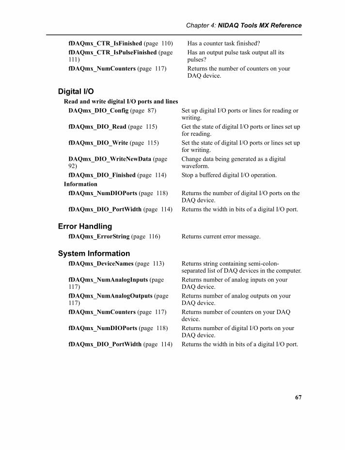
Chapter 4: NIDAQ Tools MX Reference
Digital I/ORead and write digital I/O ports and lines
DAQmx_DIO_Config (page 87) Set up digital I/O ports or lines for reading or writing.
fDAQmx_DIO_Read (page 115) Get the state of digital I/O ports or lines set up for reading.
fDAQmx_DIO_Write (page 115) Set the state of digital I/O ports or lines set up for writing.
DAQmx_DIO_WriteNewData (page 92)
Change data being generated as a digital waveform.
fDAQmx_DIO_Finished (page 114) Stop a buffered digital I/O operation.Information
fDAQmx_NumDIOPorts (page 118) Returns the number of digital I/O ports on the DAQ device.
fDAQmx_DIO_PortWidth (page 114) Returns the width in bits of a digital I/O port.
Error HandlingfDAQmx_ErrorString (page 116) Returns current error message.
System InformationfDAQmx_DeviceNames (page 113) Returns string containing semi-colon-
separated list of DAQ devices in the computer.fDAQmx_NumAnalogInputs (page 117)
Returns number of analog inputs on your DAQ device.
fDAQmx_NumAnalogOutputs (page 117)
Returns number of analog outputs on your DAQ device.
fDAQmx_NumCounters (page 117) Returns number of counters on your DAQ device.
fDAQmx_NumDIOPorts (page 118) Returns number of digital I/O ports on your DAQ device.
fDAQmx_DIO_PortWidth (page 114) Returns the width in bits of a digital I/O port.
fDAQmx_CTR_IsFinished (page 110) Has a counter task finished?fDAQmx_CTR_IsPulseFinished (page 111)
Has an output pulse task output all its pulses?
fDAQmx_NumCounters (page 117) Returns the number of counters on your DAQ device.
67
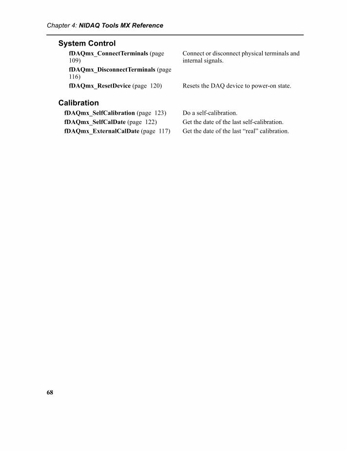
Chapter 4: NIDAQ Tools MX Reference
System ControlfDAQmx_ConnectTerminals (page 109)
Connect or disconnect physical terminals and internal signals.
fDAQmx_DisconnectTerminals (page 116)fDAQmx_ResetDevice (page 120) Resets the DAQ device to power-on state.
CalibrationfDAQmx_SelfCalibration (page 123) Do a self-calibration.fDAQmx_SelfCalDate (page 122) Get the date of the last self-calibration.fDAQmx_ExternalCalDate (page 117) Get the date of the last “real” calibration.
68
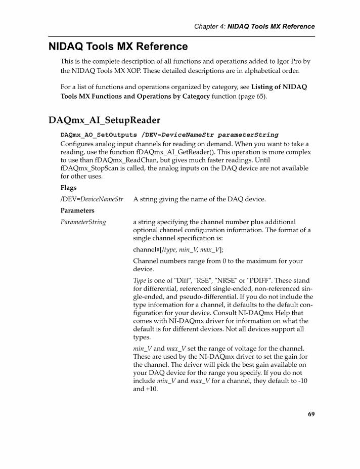
Chapter 4: NIDAQ Tools MX Reference
NIDAQ Tools MX ReferenceThis is the complete description of all functions and operations added to Igor Pro by the NIDAQ Tools MX XOP. These detailed descriptions are in alphabetical order.
For a list of functions and operations organized by category, see Listing of NIDAQ Tools MX Functions and Operations by Category function (page 65).
DAQmx_AI_SetupReaderDAQmx_AO_SetOutputs /DEV=DeviceNameStr parameterString
Configures analog input channels for reading on demand. When you want to take a reading, use the function fDAQmx_AI_GetReader(). This operation is more complex to use than fDAQmx_ReadChan, but gives much faster readings. Until fDAQmx_StopScan is called, the analog inputs on the DAQ device are not available for other uses.
Flags
/DEV=DeviceNameStr A string giving the name of the DAQ device.
Parameters
ParameterString a string specifying the channel number plus additional optional channel configuration information. The format of a single channel specification is:
channel#[/type, min_V, max_V];
Channel numbers range from 0 to the maximum for your device.
Type is one of "Diff", "RSE", "NRSE" or "PDIFF". These stand for differential, referenced single-ended, non-referenced sin-gle-ended, and pseudo-differential. If you do not include the type information for a channel, it defaults to the default con-figuration for your device. Consult NI-DAQmx Help that comes with NI-DAQmx driver for information on what the default is for different devices. Not all devices support all types.
min_V and max_V set the range of voltage for the channel. These are used by the NI-DAQmx driver to set the gain for the channel. The driver will pick the best gain available on your DAQ device for the range you specify. If you do not include min_V and max_V for a channel, they default to -10 and +10.
69

Chapter 4: NIDAQ Tools MX Reference
Each channel specification is separated from the next by a semi-colon.
Examples:
"0; 1;"
"1/DIFF, 0, 1; 3/NRSE, -1, 1;"
Each example sets up two channels for analog input. The first uses channels 0 and 1 and accepts default value for type. The voltage range defaults to +-10V.
The second example uses channels 1 and 3. Channel 1 is set for differential inputs and a range of 0 to 1 V. Channel three is set for non-reference single-ended input, and a range of -1 to 1 V.
DetailsTask creation and destruction is very slow. Reading the inputs is about 500 times faster when you use DAQmx_AI_SetupReader and fDAQmx_AI_GetReader instead of fDAQmx_ReadChan.
The disadvantage is that DAQmx_AI_SetupReader creates an analog input task which occupies the analog inputs so that they cannot be used in any other way. If you use a subset of the analog inputs with this operation, then you cannot do anything with the other outputs until you destroy the task using fDAQmx_ScanStop.
DAQmx_AO_SetOutputsDAQmx_AO_SetOutputs /DEV=DeviceNameStr [/CRNT=[currentMode]]
[/KEEP=[keepTask]] parameterString
Configures analog output channels and sets them to specified voltage or current (if supported by your DAQ device). Sets all outputs in a single call.
Flags
/DEV=DeviceNameStr A string giving the name of the DAQ device.
/CRNT[=currentMode] If your DAQ device supports current outputs, use this flag to select current output mode. Note that in that case, min V and max V in the Parameter String are actually currents in Amps.
/KEEP[=keepTask] If the /KEEP flag is present and keepTask is non-zero or absent, the task created for the operation is not destroyed when the operation returns to Igor.
70

Chapter 4: NIDAQ Tools MX Reference
Parameters
ParameterString a string specifying the voltage or current setting for a chan-nel, the channel number, plus additional optional channel configuration information. The format of a single channel specification is:
outputSetting, channel#[, min_V, max_V]
outputSetting is in either Volts or Amps, depending on the /CRNT flag.
Channel numbers range from 0 to the maximum for your device.
min_V and max_V set the range of voltage or current for the channel. These are used by the NI-DAQmx driver to set the reference voltage or current for the channel, if that is possi-ble. If you do not include min_V and max_V for a channel, they default to -10 and +10.
If you use the /CRNT flag to select current outputs, min_V and max_V are actually currents specified in Amps, but the defaults remain -10 and 10, so with current outputs, the min_V and max_V parameters must be included.
Each channel specification is separated from the next by a semi-colon.
Examples:
"5.5, 0; 3.2, 1;""0.001, 1, 0, 0.04; 0.035, 3, 0, 0.04;"
Each example sets the outputs for two channels. The first uses channels 0 and 1 and sets them to 5.5 and 3.2 volts respectively. The voltage range defaults to +-10V.
The second example uses channels 0 and 3 (some devices have four analog output channels, most have two), with set-ting appropriate for use with /CRNT=1. Channel 1 is set to 1 mA with a range of 0 to 40 mA. Channel 3 is set to 35 mA with the same range.
DetailsTask creation and destruction is very slow. Changing the outputs is about 500 times faster when you use /KEEP=1. Setting the analog outputs is even faster if you use fDAQmx_AO_UpdateOutputs (page 109) after an initial call to DAQmx_AO_SetOutputs.
71

Chapter 4: NIDAQ Tools MX Reference
The disadvantage of using /KEEP=1 is that keeping the task rather than creating it and destroying it on every call occupies the analog outputs so that they cannot be used in any other way. If you use a subset of the analog outputs with this operation, then you cannot do anything with the other outputs until you destroy the analog output task.
To destroy the task when you are finished with it, you have two choices: 1) call DAQmx_AO_SetOutputs one more time with /KEEP=0 (or with no /KEEP flag) or 2) call fDAQmx_WaveformStop (page 124). Calling DAQmx_AO_SetOutputs one more time gives you a chance to set the outputs to some final (resting?) state.
DAQmx_CTR_CountEdgesDAQmx_CTR_CountEdges /DEV=DeviceNameStr [/EDGE=edge]
[/INIT=initialCount] [/DIR=direction] [/CLK=clkSource [/FIFO=fifoName] [/WAVE=waveName /RPT]] /ERRH=ErrorHookStr /EOSH=EndOfScanHookStr /RPTH=RepeatHookStr [/STRT[=startSpec]] [/SRC=sourceTerminal] [/TRIG={trigspec}] [/PAUS={pauseTriggerSpec}] [/OUT=outputTerminal] counter
Sets up and optionally starts an edge-counting operation using an onboard coun-ter/timer. Use fDAQmx_CTR_ReadCounter (page 111) or fDAQmx_CTR_ReadWithOptions (page 112) to retrieve the current count. Use /WAVE or /FIFO to specify a buffered counting operation in which the count is peri-odically retrieved into a wave or Igor FIFO.
Flags
/DEV=DeviceNameStr A string giving the name of the DAQ device.
/EDGE=edge Determines which edge is counted.
edge = 0 falling edge. edge = 1 rising edge.
Default is /EDGE=1.
/INIT=initialCount Pre-sets the counter contents before any edges have been counted. Default is zero.
/DIR=direction Sets whether to count up or down.
direction = -1: count down direction = 0: controlled by external signal direction = 1: count up
Connections for direction = 0:M-series PFI 10: pin 45 PFI 11:pin 46E- and S-series port0/line6: pin 16 port0/line7: pin 48
72

Chapter 4: NIDAQ Tools MX Reference
For other devices, consult your documentation.
/ERRH=ErrorHookStr A string containing a command to be executed if an error occurs during background counting into a wave or FIFO.
/EOSH=EndOfScanHookStr A string containing a command to be executed background counting into a wave is finished. Since FIFO operations never finish, this is of use only for operations configured with the /WAVE flag.
/FIFO=fifoName The name of an Igor FIFO to receive multiple readings. If you use /FIFO, you must also specify a source of clock pulses using /CLK.
This operation does not use an on-board timebase: you must supply a source of clock pulses using the /CLK flag. Because an external clock source is used, the period set by the FIFOs deltat setting does not set the sampling rate. However, the sampling rate is still passed to the NI-DAQmx driver, which may use the information to optimize the counter set-up. You should set deltat to the maximum rate you expect.
Using a FIFO implies taking counter readings indefinitely.
/RPTH=RepeatHookStr A string containing a command to be executed at the end of each repeat when using the /RPT flag. Note that the hook command will execute after one repeat is finished, and before the next is started. Consequently, the command will delay the start of the next repeated operation.
/STRT=startSpec Controls whether the counting operation is started immedi-ately.
NOTE: If you have specified a trigger, starting is not the same as triggering. Until the operation is started, nothing happens even when a trigger signal is applied. Once the operation is started, counting waits until a trigger signal is applied
If startSpec is zero, the counting is not started automatically. In that case, use the fDAQmx_CTR_Start (page 113) func-tion to start counting.
If startSpec is non-zero, counting is started before DAQmx_CTR_CountEdges returns control to Igor.
Default is /STRT=1.
/SRC=sourceTerminal Sets the connector terminal where the pulses to be counted are applied to the pin named by the sourceTerminal string. Commonly a PFI pin; this would have a name like
73

Chapter 4: NIDAQ Tools MX Reference
/devname/PFI6 where “Device” would be the same string used for the Device parameter.
This could also be an internal signal like /devname/Ctr1InternalOutput.
Default depends on your DAQ device; usually PFI 8 (pin 37) for counter 0, and PFI 3 (pin 42) for counter 1.
/TRIG={source [, type, edge]} Sets up a trigger. The counting operation waits for the speci-fied signal before counting commences.
source is a string giving the source terminal for the trigger sig-nal. Usually this will be something like /devname/pfi1, where “Device” is the same string used for DeviceNameStr.
type is a number specifying what type of trigger to use. Val-ues are:
type = 0 Disable triggers (just like not using /TRIG)type = 1 Digital trigger.
Default is type 1.
edge controls the part of the trigger pulse used for triggering. Values are:
edge = 0 Falling edgeedge = 1 Rising edge
Default is 1.
Note that analog triggering is not supported. However, if you have an analog trigger set up for some other operation, you could set source to /devname/AnalogComparisonEvent.
/PAUS={source, pretrigSamples [, type, edgeslopewhen, level1, level2]} Sets up a pause trigger, allowing hardware gating of count-ing. That is, no source edges are counted when the pause trigger is asserted. (It seems like “gate” would be a better term than “trigger”; National Instruments refers to it as a trigger).
source is a string giving the source terminal for the trigger sig-nal. Usually this will be a PFI input, like /devname/pfi1, where “Device” is the same string used for DeviceNameStr. There is no default source.
type is a number specifying what type of trigger to use. Val-ues are:
type = 0 Disable (no pause trigger)
74

Chapter 4: NIDAQ Tools MX Reference
type = 1 Digitaltype = 2 Analog leveltype = 3 Analog window
Default is type = 1.
edgeslopewhen controls when the scanning operation is sus-pended. Values are:
edgeslopewhen = 0 low level (digital), below level1 (analog level) or outside the window (analog window)
edgeslopewhen = 1 high level, above level1, or inside window.
Default is edgeslopewhen = 1.
level1 sets the voltage threshold for analog level trigger, or the voltage at the bottom of the analog window. Ignored for digital triggering.
Default is 0.0.
level2 sets the voltage at the top of analog window. Ignored for digital or analog level triggering.
Default is 0.0.
/OUT=outputTerminal Sets the connector terminal where the counter output appears to the terminal named by the outputTerminal string. The counter output changes when -1 count is reached by counting up from a negative initial count, or when zero count is reached while counting down from a positive initial count, or by rolling over because the count exceeded the capacity of the counter.
An edge-counting operation normally does not put its output on a terminal.
The default depends on your DAQ device.
/WAVE=waveName Specifies a wave to receive multiple results.
This operation does not use an on-board timebase: you must supply a source of clock pulses using the /CLK flag. Because an external clock source is used, the period set by the wave's X scaling does not set the sampling rate. However, the sam-pling rate is still passed to the NI-DAQmx driver, which may use the information to optimize the counter set-up. You should set the wave's X scaling to the maximum rate you expect.
75

Chapter 4: NIDAQ Tools MX Reference
/RPT[=repeatSpec] When taking multiple readings into a wave, this flag will cause the operation to be repeated endlessly. That is, once the entire wave is filled with counter results, the whole thing starts over at the beginning of the wave.
Repeated operation is selected if repeatSpec is missing or equal to 1. If repeatSpec is zero or you do not use the /RPT flag, the operation does not repeat.
This flag has effect only when using the /WAVE flag.
/CLK=clkSource If you use the /WAVE flag or /FIFO flag to specify a buffered counting operation, you must also specify a source of clock pulses. These pulses will set the interval at which the counter is sampled.
A typical clock source might be "/dev1/pfi0". To synchronize the counter readings with sampling in an analog input scan-ning operation, use /devname/ai/sampleclock.
Parameter
counter Number of the counter to use for the operation. Most DAQ devices have two counters, so the counter parameter must be either 0 or 1.
DAQmx_CTR_OutputPulseDAQmx_CTR_OutputPulse /DEV=DeviceNameStr /DELY=delay
/FREQ={frequency, dutyCycle} /KEEP[=doKeep] /SEC={highTime, lowTime} /TICK={highTicks, lowTicks} /IDLE=idleState /NPLS=numPulses /PAUS={pauseTriggerSpec} /RATE=timebaseRate /STRT[=startSpec] /TBAS=timeBaseTerminal /TRIG={trigspec} /OUT=outputTerminal counter
Sets up and optionally starts an output pulse operation. You can ask for a single pulse, continuous pulse train, or a finite pulse train.
Flags
/DEV=DeviceNameStr A string giving the name of the DAQ device.
/DELY=delay Delay, in seconds, before starting the pulse or pulse train.
Default is zero.
/DUTY=dutyCycle Sets the duty cycle of pulses, a number between zero and one giving the ratio of the ON part of the pulse to the total period of the pulse. Must be in the range 0 to 1.
76

Chapter 4: NIDAQ Tools MX Reference
Default is 0.5.
/FREQ={frequency, dutyCycle} Sets pulse train output cycle in terms of pulse frequency.
frequency = Frequency, in pulses per second, of the pulse train. For a single pulse, this is the inverse of the pulse period. The period includes both the high and low parts of the pulse.
dutyCycle = the duty cycle of pulses, a number between zero and one giving the ratio of the ON part of the pulse to the total period of the pulse. Must be in the range 0 to 1. Default is 0.5.
/KEEP=doKeep If doKeep is non-zero or missing, the counter task is not destroyed when pulse generation is finished. This can make re-starting the pulse much faster.
/SEC={highTime, lowTime} Sets pulse train output cycle in terms of time in seconds that the pulse spends in the high and low states.
highTime = the period of time the pulse spends in the high logic state.
lowTime = the period of time the pulse spends in the low logic state. Default is to be equal to highTime.
Total pulse period is the sum of lowTime and highTime. If you do not specify lowTime, then the pulse period is twice high-Time.
/TICK={highTicks, lowTicks} Sets pulse train output cycle in terms of the number of time-base ticks that the pulse spends in the high and low states.
highTicks = the number of ticks the pulse spends in the high logic state.
lowTicks = the number of ticks the pulse spends in the low logic state. Default is to be equal to highTicks.
Total pulse period is the sum of lowTicks and highTicks. If you do not specify lowTicks, then the pulse period is twice highTicks.
The timebase in this mode is by default /devname/20MHzTimeBase, so the ticks are by default 50 nanoseconds apart. If your device does not have a 20 MHz timebase, you must specify a timebase using /TBAS.
77

Chapter 4: NIDAQ Tools MX Reference
/IDLE=idleState Specifies whether the “resting” state of the counter output is at high logic level or low.
idleState = 0 low level (what you mostly want)idleState = 1 high level
Default is idleState = 0.
/NPLS=numPulses Sets the number of pulses that should be produced. Setting numPulses to zero requests a continuous pulse train. The maximum number is determined by the characteristics of the counter on your DAQ device.
Note that setting numPulses > 1 will use another counter on the DAQ device to count the pulses being produced. This will make this other counter unavailable for use.
Default is numPulses = 1.
/PAUS={source, pretrigSamples [, type, edgeslopewhen, level1, level2]} Sets up a pause trigger, allowing hardware gating of pulse generation. When the pause trigger is asserted, the pulse gen-eration is suspended. The counter output is left either high or low if it was in the high or low state when the pause trigger is asserted.
source is a string giving the source terminal for the trigger sig-nal. Usually this will be a PFI input, like /devname/pfi1, where "Device" is the same string used for DeviceNameStr. There is no default source.
type is a number specifying what type of trigger to use. Val-ues are:
type = 0 Disable (no pause trigger)type = 1 Digitaltype = 2 Analog leveltype = 3 Analog window
Default is type = 1.
edgeslopewhen controls when the scanning operation is sus-pended. Values are:
edgeslopewhen = 0 low level (digital), below level1 (analog level) or outside the window (analog window)
edgeslopewhen = 1high level, above level1, or inside window.
Default is edgeslopewhen = 1.
78

Chapter 4: NIDAQ Tools MX Reference
level1 sets the voltage threshold for analog level trigger, or the voltage at the bottom of the analog window. Ignored for digital triggering.
Default is 0.0.
level2 sets the voltage at the top of analog window. Ignored for digital or analog level triggering.
Default is 0.0.
/RATE=timebaseRate Specifies the frequency of the timebase used for timing pulses (see the /TBAS flag). This number will be used to scale quantities like the delay (/DELY) and frequency (/FREQ) from seconds to timebase pulses.
If you use /TBAS to set the timebase to an internal timebase (such as /devname/80MhzTimebase) the rate must match the DAQmx system's notion of the actual timebase rate. But if you don't include /RATE, it doesn't matter.
If you use /TBAS to select some other signal such as a PFI pin where you supply your own timebase pulses, you must use /RATE to tell the system what the rate is. In this case, the sys-tem believes anything you tell it.
If you set timeBaseRate to -1, the flag is ignored. This makes it easier to write compiled function code without lots of condi-tionals choosing amongst various combinations of flags.
/STRT=startSpec Controls whether pulse-train generation is started immedi-ately.
If you have specified a trigger, starting is not the same as trig-gering. Until the operation is started, nothing happens even when a trigger signal is applied. Once the operation is started, pulse generation waits until a trigger signal is applied, if you have specified a trigger using /TRIG.
If startSpec is zero, the scanning operation is not started auto-matically. In that case, use the fDAQmx_CTR_Start (page 113) function to start scanning.
If startSpec is non-zero, pulse-train generation is started before DAQmx_CTR_OutputPulse returns control to Igor.
Default is /STRT=1.
/TBAS=timeBaseTerminal String specifying the source terminal for timebase pulses. This may be an internal timebase such as
79
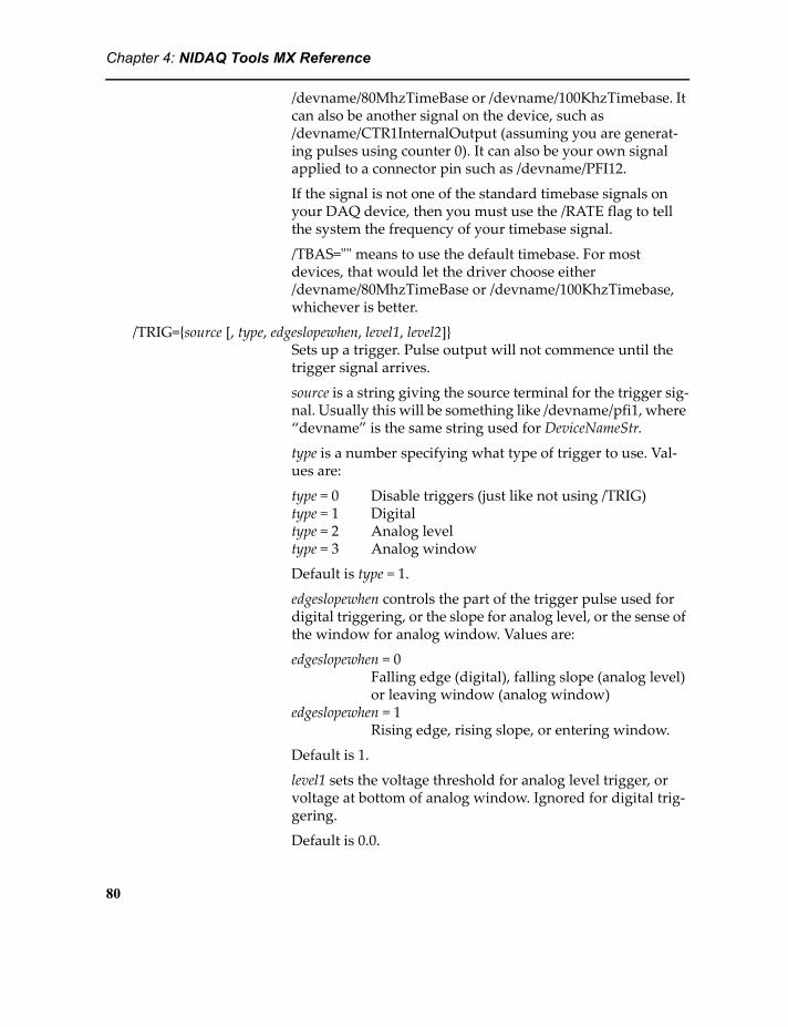
Chapter 4: NIDAQ Tools MX Reference
/devname/80MhzTimeBase or /devname/100KhzTimebase. It can also be another signal on the device, such as /devname/CTR1InternalOutput (assuming you are generat-ing pulses using counter 0). It can also be your own signal applied to a connector pin such as /devname/PFI12.
If the signal is not one of the standard timebase signals on your DAQ device, then you must use the /RATE flag to tell the system the frequency of your timebase signal.
/TBAS="" means to use the default timebase. For most devices, that would let the driver choose either /devname/80MhzTimeBase or /devname/100KhzTimebase, whichever is better.
/TRIG={source [, type, edgeslopewhen, level1, level2]} Sets up a trigger. Pulse output will not commence until the trigger signal arrives.
source is a string giving the source terminal for the trigger sig-nal. Usually this will be something like /devname/pfi1, where “devname” is the same string used for DeviceNameStr.
type is a number specifying what type of trigger to use. Val-ues are:
type = 0 Disable triggers (just like not using /TRIG)type = 1 Digitaltype = 2 Analog leveltype = 3 Analog window
Default is type = 1.
edgeslopewhen controls the part of the trigger pulse used for digital triggering, or the slope for analog level, or the sense of the window for analog window. Values are:
edgeslopewhen = 0Falling edge (digital), falling slope (analog level) or leaving window (analog window)
edgeslopewhen = 1Rising edge, rising slope, or entering window.
Default is 1.
level1 sets the voltage threshold for analog level trigger, or voltage at bottom of analog window. Ignored for digital trig-gering.
Default is 0.0.
80
Chapter 4: NIDAQ Tools MX Reference
level2 sets the voltage at top of analog window. Ignored for digital or analog level triggering.
Default is 0.0.
/OUT=outputTerminal Sets the connector terminal where the counter output appears to the terminal named by the outputTerminal string.
Parameter
counter Number of the counter to use for the operation. Most DAQ devices have two counters, so the counter parameter must be either 0 or 1.
DetailsThis operation allows you to specify the pulse period in terms of seconds, timebase ticks, or frequency depending on what best suits your needs. If it is important that the pulses be exactly synchronized to some clock source, then you should use ticks mode and specify the clock source as the timebase for this operation.
If you use an external timebase source, or if you use the output of another counter or the analog input sample clock, when you use /SEC or /FREQ you must use the /RATE flag to tell the driver the frequency of your timebase. That is required so that the driver can calculate how many pulses of your timebase to count for timing the pulses.
If you use either time mode (/SEC) or ticks mode (/TICK) you set the time for the high and the low parts of the pulse; the total pulse period is the sum of the low and high times. If you specify only the high time, the low time defaults to be equal to the high time, resulting in a pulse period twice the high time.
If you use frequency mode (/FREQ) the frequency sets the total pulse period, and the duty cycle defaults to 0.5. Thus, by default, the high and low times in frequency mode are half the period set by the specified frequency.
In either time mode (/SEC) or frequency mode (/FREQ) the driver calculates the number of timebase ticks based on its knowledge of the timebase frequency. This cal-culation may result in round-off errors, which could, in turn, cause uncertainty as to exactly how many timebase ticks are counted for a pulse period. If it is important that the pulses be exactly as long as a certain number of ticks, use ticks mode (/TICK).
The pause trigger (/PAUS) can be used only with continuous pulse generation. That is, it cannot be used to lengthen a single pulse.
81

Chapter 4: NIDAQ Tools MX Reference
DAQmx_CTR_PeriodDAQmx_CTR_Period /DEV=DeviceNameStr /EDGE=edge /FIFO=fifoName
/MTHD={method, parameter} /OUT=outputTerminal /R={minVal, maxVal} /RATE=timebaseRate /STRT[=startSpec] /SRC=sourceTerminal /TRIG={trigspec} /WAVE=waveName /RPT /ERRH=ErrorHookStr /EOSH=EndOfScanHookStr /RPTH=RepeatHookStr /TBAS=timeBaseTerminal /UNIT=units
DAQmx_CTR_PulseWidthDAQmx_CTR_PulseWidth /DEV=DeviceNameStr /EDGE=edge
/FIFO=fifoName /MTHD={method, parameter} /OUT=outputTerminal /R={minVal, maxVal} /RATE=timebaseRate /STRT[=startSpec] /SRC=sourceTerminal /TRIG={trigspec} /WAVE=waveName /RPT /TBAS=timeBaseTerminal /UNIT=units
Sets up and optionally starts a period or pulse width measurement operation.
DAQmx_CTR_Period measures the time between two pulse edges of the same sense. It is intended for measuring the period of a pulse train.
DAQmx_CTR_PulseWidth measures the time between two pulse edges of opposite sense. It is intended for measuring the width of isolated pulses.
That is:
Pulse WidthPeriod
Positive Pulse (/EDGE=1, the default)
Pulse WidthPeriod
Negative Pulse (/EDGE=0)
Flags
/DEV=DeviceNameStr A string giving the name of the DAQ device.
82

Chapter 4: NIDAQ Tools MX Reference
/EDGE=edge Determines whether rising or falling edges are used for mea-suring period, or whether the first edge of pulse width mea-surement is a rising or falling edge.
edge = 0 falling edge.edge = 1 rising edge.
Default is /EDGE=1.
See the illustration above for a graphical representation of the meaning of edge.
/ERRH=ErrorHookStr A string containing a command to be executed if an error occurs during background counting into a wave or FIFO.
/EOSH=EndOfScanHookStr A string containing a command to be executed background counting into a wave is finished. Since FIFO operations never finish, this is of use only for operations configured with the /WAVE flag.
/FIFO=fifoName Specifies an Igor FIFO to receive multiple readings. If you use /FIFO, you must also specify a source of clock pulses using /CLK.
This operation does not use a timebase: A new measurement is taken every time an appropriate source edge is seen. That is, if the period of the measured signal is 100 ms, you will get a new measurement every 100 ms.
Using a FIFO implies taking counter readings indefinitely.
/MTHD={method, parameter}
DAQmx_CTR_Period only. Selects one of three methods for measuring pulse width. method selects which method to use:
method = 0: One-counter methodmethod = 1: Two-counter timedmethod = 2: Two-counter divider
The default method is method = 0.
If method is zero, parameter is ignored.
If method is one, parameter sets the measurement time in the units selected by /UNIT. The default is 1.0.
If method is two, parameter sets the factor by which to divide the input pulse train. The default is 10.
Methods 1 and 2 use a second counter to achieve greater accuracy. Note that the use of a second counter means that
83

Chapter 4: NIDAQ Tools MX Reference
you must use an even-numbered counter, and counter n+1 will be used as well, making it unavailable for other pur-poses.
A discussion of the details is beyone the scope of this manual; please refer to the NI-DAQmx C Reference. See the section NI-DAQmx Key Concepts->Counters->Paired Counters.
/OUT=outputTerminal Sets the connector terminal where the counter output appears to the terminal named by the outputTerminal string. The counter output changes when zero count is reached. It is hard to see how the output would be useful in a period or pulse width measurement.
/R={minVal, maxVal} Used to set the expected minimum and maximum values to be read. This information is used by the DAQmx driver to select the best settings. The values for minVal and maxVal are in the units specified by the /UNIT flag.
/RATE=timebaseRate Specifies the frequency of the timebase (see the /TBAS flag). This number will be used to scale quantities like the minVal and maxVal (/R) and the output values from timebase pulses to seconds.
If you use /TBAS to set the timebase to an internal timebase (such as /devname/80MhzTimebase) the rate must match the DAQmx system's notion of the actual timebase rate.
If you use /TBAS to select some other signal such as a PFI pin where you supply your own timebase pulses, the system takes your word for it.
/SRC=sourceTerminal Sets the connector terminal where the pulses to be measured are applied. Usually one of the PFI pins, like /devname/PFI0.
The default source depends on the DAQ device you are using.
/STRT=startSpec Controls whether the operation is started immediately when the operation executes.
If you have specified a trigger, starting is not the same as trig-gering. Until the operation is started, nothing happens even when a trigger signal is applied. Once the operation is started, waveform generation waits until a trigger signal is applied, if you have specified a trigger using /TRIG.
If startSpec is zero, the operation is not started automatically. In that case, use the fDAQmx_CTR_Start (page 113) func-tion to start the measurement.
84

Chapter 4: NIDAQ Tools MX Reference
If startSpec is non-zero, the operation is started before the operation returns control to Igor.
Default is /STRT=1.
/TBAS=timeBaseTerminal Sets the source terminal for timebase pulses. This may be an internal timebase such as /devname/80MhzTimeBase or /devname/100KhzTimeBase. It can also be another signal on the device, such as /devname/CTR1InternalOutput (assum-ing you are generating pulses using counter 0). It can also be your own signal applied to a connector pin such as /devname/PFIn.
Pulses of the timebase signal are counted to measure the time between the pulse edges being measured.
If the signal is not one of the standard timebase signals on your DAQ device, then you must use the /RATE flag to tell the system the frequency of your timebase signal.
/TRIG={source [, type, edgeslopewhen, level1, level2]} Sets up a trigger. The measurement operation waits for the first edge after the trigger signal before starting the measure-ment.
source is a string giving the source terminal for the trigger sig-nal. Usually this will be something like /devname/pfi1, where “devname” is the same string used for DeviceNameStr.
type is a number specifying what type of trigger to use. Val-ues are:
type = 0 Disable triggers (just like not using /TRIG)type = 1 Digitaltype = 2 Analog leveltype = 3 Analog window
Default is type = 1.
edgeslopewhen controls the part of the trigger pulse used for digital triggering, or the slope for analog level, or the sense of the window for analog window. Values are:
edgeslopewhen = 0Falling edge (digital), falling slope (analog level) or leaving window (analog window)
edgeslopewhen = 1Rising edge, rising slope, or entering window.
Default is 1.
85
Chapter 4: NIDAQ Tools MX Reference
level1 sets the voltage threshold for analog level trigger, or voltage at bottom of analog window. Ignored for digital trig-gering.
Default is 0.0.
level2 sets the voltage at top of analog window. Ignored for digital or analog level triggering.
Default is 0.0.
/UNIT=units Specifies the units used to report the measurement results. Values are:
units = 0 timebase counts are scaled to seconds.units = 1 timebase counts are reported without scaling.
/WAVE=waveName Specifies a wave to receive multiple results.
This operation does not use an on-board timebase: a new measurement is taken every time an appropriate source edge is seen. That is, if the period of the measured signal is 100 ms, you will get a new measurement every 100 ms.
/RPT[=repeatSpec] When taking multiple readings into a wave, this flag will cause the operation to be repeated endlessly. That is, once the entire wave is filled with counter results, the whole thing starts over at the beginning of the wave.
Repeated operation is selected repeatSpec is missing or equal to 1. If repeatSpec is zero or you do not use the /RPT flag, the operation does not repeat.
This flag has effect only when using the /WAVE flag.
/RPTH=RepeatHookStr A string containing a command to be executed at the end of each repeat when using the /RPT flag. Note that the hook command will execute after one repeat is finished, and before the next is started. Consequently, the command will delay the start of the next repeated operation.
Parameter
counter Number of the counter to use for the operation. The number will be in the range zero to N-1 on a device having N coun-ters. Most devices have two; in that case the counter number must be either 0 or 1.
86

Chapter 4: NIDAQ Tools MX Reference
DAQmx_DIO_ConfigDAQmx_DIO_Config /DEV=DeviceNameStr /CHNG={risingChans,
fallingChans} /CLK={clockSrc[, clockEdge]} /DIR=direction /ERRH=ErrorHookStr /EOSH=EndOfScanHookStr /FIFO=fifoName /HAND /LGRP=lineGrouping /REWR=rewriteable /RPTC=continuous /WAVE={bufWave [, bufWave2, ...]} LineSpec
Executes a digital I/O operation. It can set up digital I/O lines as inputs or outputs, and it can set up a buffered operation (/WAVE for input or output or /FIFO for input only) or it can set up for individual reads under your control using fDAQmx_DIO_Read (page 115) or fDAQmx_DIO_Write (page 115).
If you set up a buffered I/O operation, the timing can be from a clock. Some hardware has a clock dedicated to digital I/O; in that case the rate is set by wave scaling or by a FIFO deltaT parameter. I/O transfers can also be controlled by change events or by handshaking if the hardware supports these modes.
Flags
/DEV=DeviceNameStr A string giving the name of the DAQ device.
/CHNG={risingChans, fallingChans} For a buffered DIO operation, use change detection timing. That is, transfer a reading into an input buffer only when one of the lines in the lists changes.
For input when a line changes from low to high, include the line specification in a list in risingChans. For input when a line changes from high to low, include the line specification in a list in fallingChans. The lists in risingChans and fallingChans are lists of signals like /Dev1/port0/line1.
There is a variety of ways to specify a list of lines. If the lines are contiguous, use a specification like “/Dev1/port0/line1:3”. If the lines are not contiguous, separate lines specifications with commas: “/Dev1/port0/line2, /Dev1/port0/line4”.
/CHNG cannot be used with /CLK or /HAND.
/CLK={srcStr, edge} Specifies a clock source other than the default internal time-base. You can connect your own source of clock pulses to an external pin, or specify an internal signal like the output of a counter.
The string srcStr names the source terminal for the clock sig-nal. Usually this will be something like /devname/pfi0, where “Device” is the same string used for DeviceNameStr. Common choices for internal signals might be /Dev1/ai/sampleclock,
87

Chapter 4: NIDAQ Tools MX Reference
/Dev1/ai/convertclock, /Dev1/ao/sampleclock, /Dev1/ctr0internaloutput or /Dev1/ctr1internaloutput.
The part of the clock pulse that triggers a scan is set by edge. Values are:
edge = 0 Falling edgeedge = 1 Rising edge
If you use your own clock source, the rate set by wave scaling or FIFO deltaT is ignored, except that it may be used by the NI-DAQmx driver to optimize the scanning operation.
/DIR=direction Sets the direction of I/O to either input or output. Default is input. If direction is non-zero, direction is output.
/ERRH=ErrorHookStr A string containing a command to be executed if an error occurs during a buffered DIO operation.
/EOSH=EndOfScanHookStr A string containing a command to be executed when a buff-ered I/O operation has finished. Since FIFO operations never finish, this is of use only for operations configured with the /WAVE flag.
/FIFO=fifoName Name of an Igor FIFO to receive buffered DIO input. You cannot use a FIFO for output. See Details section for more information.
/HAND Use handshake timing for buffered DIO operations. See the National Instruments documentation to learn how to set up handshake timing signals.
/LGRP=lineGrouping Specifies whether the DIO lines will be grouped into a single task channel (lineGrouping = 0, the default) or if each line will be a single channel (lineGrouping = 1).
The practical implication of this choice is that lineGrouping=0 causes the entire port to be reserved for the operation, and each line has its appropriate binary digit value. For buffered operations, a single wave or FIFO channel receives the data from all lines in the operation. This would be most appropri-ate for applications that read or write numbers or command bytes to or from an instrument.
If lineGrouping = 1, then the lines are treated as individual channels. The binary values when you read/write using fDAQmx_DIO_Read (page 115) or fDAQmx_DIO_Write (page 115) are based on the position of the line in the specifi-cation list. For buffered operations, you must supply a wave
88
Chapter 4: NIDAQ Tools MX Reference
for each line, or a FIFO channel for each line. This grouping is most appropriate for lines that control individual valves or signal lights, or input lines that read control switches or on/off indicators.
/REWR={regenMode, transferCondition, transferFraction, transferTimeout} A buffered output operation using waves can have new data installed to generate a different sequence of outputs. Use the DAQmx_DIO_WriteNewData (page 92) operation to change the data being generated.
Since we were unable to find an implementation that works consistently, we pass along some obscure settings to you:
regenMode controls the NI-DAQmx property that allows or disallows generation of the data in the driver’s memory buf-fer multiple times. Values are
0: DAQmx_Val_DoNotAllowRegen1: DAQmx_Val_AllowRegen
The values are NI-DAQmx symbolic constants. See the NI-DAQmx C Function Help for the function DAQmxSetWriteRegenMode for details.
It is likely that you need to set regenMode = 0 to prevent a glitch in which one data set is interrupted by another in the middle.
transferCondition controls the NI-DAQmx Data Transfer Request property. It controls when the DAQ device requests a transfer of data from computer memory into its on-board memory. Values are:
0: DAQmx_Val_OnBrdMemEmpty1: DAQmx_Val_OnBrdMemHalfFullOrLess2: DAQmx_Val_OnBrdMemNotFull
The values are NI-DAQmx symbolic constants. See the NI-DAQmx C Function Help for the function DAQmxSetDODataXferReqCond for details.
It appears that transferCondition = 0 should give the most responsive update.
The way the re-write is implemented is that the NIDAQmx XOP checks every time it gets an IDLE message to see if the space available in the memory buffer is greater than some fraction of the total size. If it is, it tries to write data to the driver’s memory buffer. transferFraction is a number between
89

Chapter 4: NIDAQ Tools MX Reference
0 and 1 that sets this condition. transferTimeout is a number greater than 0 that sets the timeout on the write.
The write is done with one of the DAQmxDIOWritexxx func-tions.
You are on your own...
/RPTC=continuous If continuous is non-zero, a buffered output operation will repeat the data over and over indefinitely. Stop the genera-tion with fDAQmx_DIO_Finished (page 114).
/RPTC Just like /RPTC=1.
/WAVE={bufWave [, bufWave2, ...]} Specifies a buffered DIO operation using waves to receive data or to provide output data. If you use /LGRP=0 or if you do not use /LGRP, provide just one wave. If you use /LGRP=1, provide a wave for each line. You can specify up to 32 waves; the number must match the number of channels configured for the operation
Parameters
LineSpec LineSpec specifies a list of DIO lines or a port for the DIO operation. You can use a comma-separated list: “/dev1/port0/line0,/dev1/port0/line1”, or a range specifica-tion: “/dev1/port0/line0:1”, or include an entire port: “/dev1/port0” (only for /LGRP=0).
DetailsBecause you can have more than one DIO operation defined for a single device, DAQmx_DIO_Config stores a task index into a variable called V_DAQmx_DIO_TaskNumber. Calls to DIO control functions require this task index.
If you use /WAVE to specify a buffered DIO operation using waves to hold output data, or to receive input data, the wave scaling is used to set the clock rate for the transfers. This is overridden when you use /CLK, /HAND, or /CHNG, each of which specifies a different sort of alternative to the clock generated by the DAQ device.
NOTE for most devices: Most DAQ devices do not have a dedicated clock for buffered digital IO operations. Such devices use what National Instruments calls "correlated DIO", which is just their term for using a source of pulses from somewhere else as the clock. On devices that support "correlated DIO", you are required to use the /CLK flag to specify a clock source. That clock source could be a counter pulse train output, in which case the clock source could be something like /CLK={"/Devname/Ctr0InternalOutput"} to use the output of counter zero. Another possibility is to sync the DIO operation to the analog input scan or waveform output operation using either /CLK={"/Devname/ai/sampleclock"} or
90

Chapter 4: NIDAQ Tools MX Reference
/CLK={"/Devname/ao/sampleclock"}. Yet another possibility is to use a pulse train from some external source, fed in through one of the PFI pins.
If you use /WAVE with /LGRP=0 (all lines are combined in a single task channel), then the data are represented as a binary number with each line represented as a binary digit. The best number type to use for the wave would be an integer type that is as wide as the port containing the lines. In most cases that would be a byte wave (8 lines or bits in a port, use Make/B/U to make the wave), but some devices have 32-bit ports and it would be better to use a 32-bit integer wave (Make/I/U).
If you use /WAVE with /LGRP=1 (each line is a separate task channel), then you must specify one wave for each line in the DIO operation. The state of each line will be rep-resented by a 0 or 1, so you should use byte wave (Make/B/U) for these waves. Even so, it is wasteful to use eight bits to represent 0 or 1...
Waves of any number type are accepted, and the data will be converted appropriately. But using the wrong number type may result in truncation of the data on 32-bit ports. Clearly, using 8-bit or 16-bit waves to hold 32-bit data will not work well. But less obviously, a 32-bit float (single precision floating-point) has only 24 bits of mantissa, so a 32-bit number will potentially lose low-order bits.
An Igor FIFO can be used for input only. As with Waves, using /LGRP=0 will combine all lines of a port into a single integer. Thus, you must use a FIFO with one channel. If you use /LGRP=1, each line is represented separately, so you must have a FIFO chan-nel for each line in the operation. The same considerations for the FIFO channel num-ber type apply as for wave number type.
When you use /LGRP=0, all lines of a DIO port are represented by a single integer. Thus, if you specify, for instance, "/dev1/port0/line1,/dev1/port0/line3" and both lines are high, when you read the data with fDAQmx_DIO_Read (page 115) the result will be 10 (21 + 23). Because you specified only the two lines, the other lines in the port will always be zero in the result, but the bits used to represent the lines are those that would be used if all lines in the port were read.
On the other hand, if you use /LGRP=1, only the specified lines are included in the returned data, in the order in which you listed them. Thus, the example would return 3 (20 + 21, with bit 0 representing line 1 and bit 1 representing line 3).
These considerations of line grouping apply to output (fDAQmx_DIO_Write on page 115) as well as input.
Using the /RPTC flag it is possible to generate a sequence of outputs that repeats when the end of the data is reached. Works only with WAVE keyword for buffered output.
Using the /REWR flag along with /RPTC it is possible to change the data being gener-ated on the fly, causing the output pattern to change. However, this seems to be some-thing that most NI multi-function DAQ devices don't support well. It may work best
91

Chapter 4: NIDAQ Tools MX Reference
with a dedicated DIO device like the PCI-6534. In any case, we were not able to find a reliable implementation, so we pass along to you control over some obscure settings.
See the NI NI-DAQmx C Function Help for more details, although this particular application is not well described.
Variables
V_DAQmx_DIO_TaskNumber A number assigned by the NI-DAQmx driver identifying the task created for the operation. You use this number as the TaskIndex parameter for the various fDAQmx_DIO_XXX() functions.
DAQmx_DIO_WriteNewDataDAQmx_DIO_WriteNewData /DEV=DeviceNameStr /TASK=taskIndex
WAVE={bufWave [, bufWave2, ...]}
If a buffered digital output operation was created with DAQmx_DIO_Config (page 87) and the /REWR flag, the DAQmx_DIO_WriteNewData operation will replace the data in the buffer with new data.
Flags
/DEV=DeviceNameStr A string giving the name of the DAQ device.
/TASK=TaskIndex The value stored in the variable V_DAQmx_DIO_TaskNumber by the DAQmx_DIO_Config operation.
Parameters
WAVE=... One or more wave names containing the data to replace the current buffer. The waves must match those used originally when DAQmx_DIO_Config was called. That is, there must be the same number of waves and they must have the same number of points.
DetailsWhen you use this operation to replace the data in a buffered digital output opera-tion, the current buffer finishes being output, then the new data starts. Consequently, it could be some time between when this operation is called and when the new data starts to appear at the digital outputs.
If the old data is in the process of being generated, either because DAQmx_DIO_Config was called with /RPTC=1, or because the buffer simply hasn't been finished, the old data finishes being generated before new data appears.
92

Chapter 4: NIDAQ Tools MX Reference
DAQmx_ScanDAQmx_Scan /DEV=DeviceNameStr [/AVE=nAverage
/BKG[=doBackground] /CLK={clockSpec} /ERRH=ErrorHookStr /EOSH=EndOfScanHookStr /PAUS={pauseTriggerSpec} /RPT[=repeatSpec] /RPTC[=repeatSpec] /RPTH=RepeatHookStr /RTRG={refTrigSpec} /SINT=sampleInterval /STRT[=startSpec] /TRIG={trigspec} [WAVES=WaveParameterString] [FIFO=FIFOParameterString]
Executes an analog input scanning operation acquiring data into Igor waves or an Igor FIFO.
You must choose either WAVES=WaveParameterString or FIFO=FIFOParameterString. You cannot use both, and you must use one or the other.
Waves and FIFO channels can be of any signed number type except 8-bit integer; unsigned is not allowed, nor is complex. All waves or FIFO channels must be of the same number type.
If you use integer waves or FIFO channels, the data is read in raw mode. That is, the data are the unscaled A/D convertor counts. For a 12-bit DAQ device, the values will range from -4096 to +4095; 16-bit devices will yield values from -32768 to +32767. It is not permitted to average integers using the /AVE flag.
If you use floating-point waves or FIFO channels, the data will be in the form of scaled voltage.
WavesFor finite-length scanning operations.
Using WAVES=WaveParameterString causes the acquired data to be stored in waves that you name in the parameter string. The amount of data acquired is set by the length of the waves; you must decide how much data you want to acquire before starting the acquisition.
Certain aspects of the acquisition are controlled by the properties of the waves you provide to receive the data. If multiple channels are being scanned, you must provide multiple waves. All the waves must have the same length. The sampling period is set by the dX factor of the wave scaling of the first wave in WaveParameterString. See Waves for Analog Input Scanning on page 47.
FIFOFor scanning operations of indeterminate length; optionally stream data to the hard disk.
Using FIFO=FIFOParameterString causes the acquired data to be stored in an Igor FIFO which is named in the parameter string. Data is acquired continuously until the operation is cancelled using fDAQmx_ScanStop (page 121).
93

Chapter 4: NIDAQ Tools MX Reference
After starting the acquisition, control returns immediately to Igor Pro; the /BKG flag is ignored. The actual acquisition of the raw data is handled by background processing. Other Igor operations, including transferring portions of the acquired data to waves, can take place while data is being acquired. FIFO’s can also automatically store the data in a disk file during acquisition.
Scanning rate is controlled by the delta T parameter of the FIFO you provide to receive the data. See Continuous Analog Input into FIFOs on page 29 and Analog Input Using FIFOs on page 48.
Flags
/DEV=DeviceNameStr A string giving the name of the DAQ device.
/AVE=nAverage Causes the scanning operation to take nAverage consecutive readings and average them for each data point returned. Note that this increases the actual scanning rate by a factor of nAverage.
/AVE={nAverage, subSamples}
Causes the scanning operation to take nAverage consecutive readings and average the first subSamples of them for each data point returned. Note that this increases the actual scan-ning rate by a factor of nAverage.
This may be useful if you are sampling a repeating waveform and you are interested in the average value of just part of it.
/BKG Causes the operation to return immediately; transfer of data during scanning into waves occurs in the background.
/BKG=doBackground If doBackground is 1, transfers occur in the background. If doBackground is 0, the DAQmx_Scan does not return until all the data are acquired (except for /STRT=0, see below).
The behavior of /BKG=0 is the default if the /BKG flag is not present.
For scanning into a FIFO or for repeated scanning (/RPT=1) this flag is ignored as data transfers always take place in the background.
/CLK={srcStr, edge} Specifies a sample clock other than the default. You can con-nect your own clock to an external pin, or take the sample clock from an internal signal like the output of a counter or the analog output waveform clock (/devname/ao/sample-clock).
The string srcStr names the source terminal for the clock sig-nal. Usually this will be something like /devname/pfi0 or
94

Chapter 4: NIDAQ Tools MX Reference
/devname/ctr0internaloutput, where “device” is the same string used for DeviceNameStr.
The part of the clock pulse that triggers a scan is set by edge. Values are:
edge = 0 Falling edgeedge = 1 Rising edge
If you use your own clock source, the scanning rate set by wave scaling or FIFO is ignored, except that it may be used by the NI-DAQmx driver to optimize the scanning operation.
/ERRH=ErrorHookStr A string containing a command to be executed if an error occurs during the scanning operation. Only used during background scanning (see the /BKG flag).
/EOSH=EndOfScanHookStr
A string containing a command to be executed when scan-ning has finished. Only used during background scanning (see the /BKG flag).
/PAUS={source, pretrigSamples [, type, edgeslopewhen, level1, level2]} Sets up a pause trigger, allowing hardware gating of the scanning operation. That is, scanning is suspended when the pause trigger is asserted, and resumes where it left off when the pause trigger is not asserted.
Calling it a trigger is a bit misleading. To me, a trigger is something that initiates an action when a signal edge is asserted. In the case of a pause trigger, the “trigger” provides control over the operation, not initiation, and the control is by a level, not an edge. I think “gate” is a better word.
source is a string giving the source terminal for the trigger sig-nal. Usually this will be a PFI input, like /devname/pfi1, where “Device” is the same string used for DeviceNameStr. There is no default source.
type is a number specifying what type of trigger to use. Val-ues are:
type = 0 Disable (no pause trigger)type = 1 Digitaltype = 2 Analog leveltype = 3 Analog window
Default is type = 1.
95
Chapter 4: NIDAQ Tools MX Reference
edgeslopewhen controls when the scanning operation is sus-pended. Values are:
edgeslopewhen = 0Falling edge (digital), falling slope (analog level) or leaving window (analog window)
edgeslopewhen = 1Rising edge, rising slope, or entering window.
Default is edgeslopewhen = 1.
level1 sets the voltage threshold for analog level trigger, or the voltage at the bottom of the analog window. Ignored for digital triggering.
Default is 0.0.
level2 sets the voltage at the top of analog window. Ignored for digital triggering or analog level triggering.
Default is 0.0.
/RPT (for WAVES keyword only) Causes the scanning operation to be re-started when all data are acquired. The same waves are used again, overwriting previously acquired data. This causes an oscilloscope-type mode.
There may be some latency between the end of one scan and the beginning of the next, as the end of a scan is detected only during Igor's main event loop or when DoXOPIdle is called.
If the scanning operation uses a trigger, the same trigger is used for every scan. NOTE: this is different from previous versions of NIDAQ Tools.
This flag does not apply to acquisition into a FIFO.
/RPTC (for WAVES keyword only) Samples are acquired continu-ously into the waves. When the waves are filled, the next sample goes into row zero of the waves.
If the scanning operation uses a trigger, only the first scan is triggered. Subsequent scans are continuous with the first.
This mode eliminates the latency that exists between scans when using /RPT, at the expense of not using the trigger for any but the first scan. This behavior is the same as the behav-ior of fNIDAQ_ScanWavesRepeat in the older NIDAQ Tools package.
This flag does not apply to acquisition into a FIFO.
/RPT=repeatSpec
96
Chapter 4: NIDAQ Tools MX Reference
/RPTC=repeatSpec If repeatSpec is 1, just like /RPT or /RPTC. If repeatSpec is 0, just like omitting /RPT.
/RPTH=RepeatHookStr A string containing a command to be executed when a repeated scan (see /RPT flag) finishes one scan. Note that the hook command will execute after one scan is finished, and before the next scan is started. Consequently, the command will delay the start of the next repeated scan.
/RTRG={source, pretrigSamples [, type, edgeslopewhen, level1, level2]} Sets up a reference, or stop trigger, allowing pre-trigger acquisition. That is, scanning occurs continuously until the trigger is asserted. At that point, pretrigSamples data points are transferred from already-acquired samples, and scanning continues until (totalSamples - pretrigSamples) samples are acquired.
NI-DAQmx will not allow any data transfer before all sam-ples are acquired. Background scanning still works, but you will not see your waves update with new data during scan-ning.
Cannot be used with continuous acquisition into a FIFO.
source is a string giving the source terminal for the trigger sig-nal. Usually this will be /devname/pfi1, where “Device” is the same string used for DeviceNameStr. If you use "" for source, the default stop trigger input will be used, usually PFI1 or pin 10 on the DAQ device's I/O connector.
pretrigSamples is the number of samples to save from data acquired before the reference trigger arrives.
type is a number specifying what type of trigger to use. Val-ues are:
type = 0 Disable triggers (use software start)type = 1 Digitaltype = 2 Analog leveltype = 3 Analog window
Default is type = 1.
edgeslopewhen controls the part of the trigger pulse used for digital triggering, or the slope for analog level, or the sense of the window for analog window. Values are:
edgeslopewhen = 0Falling edge (digital), falling slope (analog level) or leaving window (analog window)
97

Chapter 4: NIDAQ Tools MX Reference
edgeslopewhen = 1Rising edge, rising slope, or entering window.
Default is 1.
level1 sets the voltage threshold for analog level trigger, or the voltage at the bottom of analog window. Ignored for dig-ital triggering.
Default is 0.0.
level2 sets the voltage at the top of analog window. Ignored for digital or analog level triggering.
Default is 0.0.
/SINT=sampleInterval Sets the time period between successive channels in a single scan independently of the time period between samples on one channel (the scan interval). That is, the scan interval could be 0.01 seconds and the sample interval 0.0001 seconds to approximate simultaneous sampling. For example:
DAQmx_Scan /SINT=.0001 waves="input1, 1; input2, 2"
will sample channels 1 and 2 storing the data in waves input1 and input2. The time period between sampling channel 1 and channel 2 will be set to 0.0001 seconds.
Setting sampleInterval to zero selects the default value. See page 19 for a discussion of the default.
NOTE: “Sample Interval” and “Scan Interval” are phrases used by National Instruments in their documentation for NI-DAQ Traditional. They now use the terms “AI Convert Rate” and “Sample Rate”.
/STRT=startSpec Controls whether the scanning operation is started immedi-ately. If you have specified triggers, starting is not the same as triggering. Until the operation is started, nothing happens even when a trigger signal is applied. Once the operation is started, scanning waits until a trigger signal is applied, if you have specified a trigger using /TRIG or /RTRG.
If startSpec is zero, the scanning operation is not started auto-matically. In that case, use the fDAQmx_ScanStop function to start scanning.
If startSpec is non-zero, the scanning operation is started before DAQmx_Scan returns control to Igor.
If the /STRT flag is not used, it is just like /STRT=1.
98

Chapter 4: NIDAQ Tools MX Reference
/STRT In the absence of startSpec, the /STRT flag behaves like /STRT=1.
/TRIG={source [, type, edgeslopewhen, level1, level2]} Sets up a start trigger. Scanning waits for the specified signal before any scanning commences.
See the /RTRG flag for details on source, type, edgeslopewhen, level1 and level2.
Parameters
WAVES=WaveParameterString WaveParameterString specifies a wave for each channel to be scanned, plus additional channel configuration information. The format of a single channel specification is:
wavename, channel #[/type [key={info}]][, min_V, max_V, scale, offset]
Channel numbers range from 0 to N-1 for a device with N channels. Note that differential channels most likely use another channel for the negative input, and that channel is not available for use when you select differential mode. For instance, if you use channel 0 in differential mode, usually channel 8 is used for the negative input and is not available even if the device has more than 16 channels.
Type is one of "Diff", "RSE", "NRSE" or "PDIFF". These stand for differential, referenced single-ended, non-referenced sin-gle-ended, and pseudo-differential. If you do not include the type information for a channel, it defaults to the default con-figuration for your device. Consult NI-DAQmx Help that comes with NI-DAQmx driver for information on what the default is for different devices. Not all devices support all types.
key = {info} adds special attributes to a channel. See The key={info} addition to the channel specifier: on page 102 for details.
min_V and max_V set the expected range of input signals for the channel. These are used by the NI-DAQmx driver to select the best gain for the channel. If you do not include min_V and max_V for a channel, they default to -10 and +10 Volts.
scale and offset can be specified if you want the output to be something other than volts. They are applied as follows:
output = (volts - offset) * scale
99

Chapter 4: NIDAQ Tools MX Reference
Nothing beyond the channel number is required. The chan-nel type is optional, as are min_V, max_V, scale and offset. If any of min_V, max_V, scale and offset are include, all the items before it must be included. That is, if you want to specify scale, you must also specify min_V and max_V. Channel type may be omitted independently of min_V, max_V, scale and off-set.
Note that applying scale and offset when acquiring data into integer waves may give unexpected results!
Each channel specification is separated from the next by a semi-colon.
Examples:
WAVES="Input0, 0; Input1, 1;"WAVES="Current0, 1/Diff, -5, 5; Voltage, 3/RSE;"
The first example scans two channels, 0 and 1. The values for channel 0 are put into a wave called Input0, the values for channel 1 are put into a wave called Input1. The channels will be configured in the default mode for the device (usually differential mode) with an expected range from -10 V to 10 V.
The second example scans two channels, putting values from channel 1 into a wave called Current0 and values from chan-nel 3 into a wave called Voltage. The expected range for chan-nel 1 is -5 to +5 Volts; the expected range of channel 3 is -10 to +10 Volts. Channel 1 is configured as a differential input, while channel 3 is configured as a referenced single-ended input.
See Waves for Analog Input Scanning on page 47.
FIFO=FIFOParameterString FIFOParameterString specifies the name of the Igor FIFO to receive the data followed by a semicolon and a list of chan-nels, or a FIFO name followed by a list of channel number, min_V, max_V and type. Each channel string is separated from the next with a semicolon. The format of FIFOParameterString is:
FIFOname;channel #[; channel #; ...]
or
FIFOname;chan #[/type [key={info}]][, min_V, max_V, scale, offset][; channel #...;]
For instance:
100

Chapter 4: NIDAQ Tools MX Reference
FIFO="MyFifo;1;2;3"
will record data from analog input channel numbers 1, 2, and 3 into an Igor FIFO called MyFifo. The string
"MyFifo;1;2/RSE,-1,1;4,-1,1"
will record data from analog input channel number 1 with gain chosen to be appropriate for a voltage range of -10 to +10 and configured in the default mode for the DAQ device, channel 2 with gain chosen to be appropriate for a voltage range of -1 to +1 and configured as a single-ended input, and channel 4 with a range of -1 to +1 V and configured in the default mode.
The number of channels in the list must match the number of channels in the FIFO.
The two styles can be mixed in a single parameter string.
The channel type defaults to the default configuration for your device. Consult NI-DAQmx Help that comes with NI-DAQmx driver for information on what the default is for dif-ferent devices. The voltage range defaults to -10 to 10 Volts.
key = {info} adds special attributes to a channel. See The key={info} addition to the channel specifier: on page 102 for details.
scale and offset can be specified if you want the output to be something other than volts. They are applied as follows:
output = (volts - offset) * scale
Nothing beyond the channel number is required. The chan-nel type is optional, as are min_V, max_V, scale and offset. If any of min_V, max_V, scale or offset are include, all the items before it must be included. That is, if you want to specify scale, you must also specify min_V and max_V. Channel type may be omitted independently of min_V, max_V, scale and off-set.
Data from each analog input channel will be stored in the FIFO channels in the order in which they are listed in the command. Thus, the command above will record channel 1 into FIFO channel 0, analog input channel 2 into FIFO chan-nel 1, etc. The sampling rate will be taken from the FIFO’s deltaT parameter, set with the ctrlFIFO operation, unless you specify an external clock source using the /CLK flag.
101
Chapter 4: NIDAQ Tools MX Reference
You must make the FIFO and add the correct number of channels before calling DAQmx_Scan. Use the NewFIFO operation to make the FIFO and NewFIFOChan operation to add the channels to the FIFO.
DetailsWhen should you use /RPT or /RPTC?
These flags request an oscilloscope-type mode, in which the waves are repeatedly filled with data. It is useful for using a graph to monitor some process or for monitor-ing a repeating waveform.
When using /RPT, each scan is started as soon as the last one ends. It accomplishes this by stopping the acquisition task, executing your repeat hook (/RPTH, if any) then re-starting the task. Because the task is re-started for each new scan, if you have con-figured a trigger each scan waits for a trigger signal. If you have a suitable trigger sig-nal, this will keep the scans synchronized with the process you are monitoring. If you have not configured a trigger, then the next scan starts at some unknown delay rela-tive to the end of the previous scan. This delay will be a function of your computer's speed, the length of time it takes to execute the repeat hook, how much other activity there might be on your computer, and perhaps a host of other factors.
When using /RPTC, each scan is simply the next N points in a continuous acquisition. The acquisition task is continuous, the task is not stopped and re-started. Thus, there is no timing issue between the scans as there is for /RPT. But if you have configured a trigger, the trigger is used only to start the operation. Scans after the first simply con-tinue at the specified scanning rate.
Use /RPTC when you want to monitor a continuous process in which waveforms repeat in a predictable way, constantly in time, and you have no suitable trigger sig-nal to use to synchronize the scans with the start of the signal you wish to monitor.
The key={info} addition to the channel specifier:Certain keywords can be added to the type specifier in order to change certain aspects of the channel. Currently two keywords are supported: TC to set up a channel for temperature measurement using a thermocouple, and CP to specify the type of cou-pling used for the channel. The info string in the curly brackets contains information specific to the keyword.
The key must be preceded by one or more spaces or tabs.
key TC- this channel will be used to measure temperature using a thermocouple. The format of the info string is {units, TC type, Cold junction source, Cold junction value}.
units is one of C, F, K or R for Celsius, Fahrenheit, Kelvin or Rankine.
TC Type is one of standard one-letter thermocouple type desgnators J, K, N, R, S, T, B or E.
102

Chapter 4: NIDAQ Tools MX Reference
Cold junction source is 0, 1, or 2 for Built-in, Constant value, or specified channel. The specified channel option is not presently implemented.
Cold junction value is not used (ignored, or allowed to be missing) if Cold junction source is 0. It is the temperature of the cold junction if Cold junction source is 1, or the channel number of the cold junction if the source is 2.
When you use the TC key, the min_V and max_V values are interpreted as minimum and maximum temperatures rather than as voltages.
Example: set up channel 1 to measure temperature in degrees C, using a J type ther-mocouple. You have a DAQ device with built-in cold junction or a properly set up SCB-68 accessory with cold-junction compensation built in. The range of measure-ment will be 0 to 100 degrees. The channel will be set up to make a differential mea-surement (highly recommended with thermocouples).
WAVES="Input1, 1/DIFF TC={C, J, 0, 0}, 0, 100;"
key CP- specifies coupling to use with this channel. Format is CP={coupling type}, where coupling type is one of AC, DC, or GND. Most devices support only DC cou-pling; a few, such as the NI 9234 support AC coupling. The NI documentation talks about GND coupling (the channel is simply connected to ground and no measure-ment is taken) but we don't know what devices support GND.
DAQmx_WaveformGenDAQmx_WaveformGen /DEV=DeviceNameStr /BKG=timeout
/CRNT[=currentMode] /CLK={clockSpec} /NPRD=numPeriods /PAUS={pauseTrigSpec} /STRT[=startSpec] /TRIG={trigspec} ParameterString
Sets up and optionally starts an arbitrary waveform generation operation.
The shape of the waveform is controlled by the data in waves provided by you. The sample rate and number of samples is set by the wave scaling and the number of data points in the waves. You must provide a wave for each channel, but you can use the same wave for two channels if you wish (but why?). All waves must have the same length.
The data in the waves are in volts or amps.
Flags
/DEV=DeviceNameStr A string giving the name of the DAQ device.
/BKG[=timeout] Use this flag to request that DAQmx_WaveformGen wait until the waveform generation is finished before returning control to Igor. Note that while waiting, nothing in Igor will happen- no chart controls update, no menus work, etc. Use with caution.
103

Chapter 4: NIDAQ Tools MX Reference
Use timeout to control the maximum waiting time:
-1: Wait forever, if necessary0: Don't wait. This is the same as not using /BKG>0: Wait for timeout seconds before returning.
If you use a positive timeout, and the waveform hasn't fin-ished, DAQmx_WaveformGen returns with an error.
Note that you cannot use a timeout other than zero if you specify /NPRD=0, which repeats the waveform endlessly. If this were allowed, you would lock up Igor, requiring using the Task Manager to stop. Note also that /NPRD=0 is the default!
A non-zero value of timeout is also not compatible with /STRT=0.
/CRNT[=currentMode] If your DAQ device supports current outputs, use this flag to select current output mode. Note that in that case, min_V and max_V in the Parameter String are actually currents in Amps.
/CLK={srcStr, edge} Sets up the clock source for an arbitrary waveform genera-tion operation, if you want something other than the usual internal clock.
The string srcStr names the source terminal for the clock sig-nal. Usually this will be something like /devname/pfi0, where “Device” is the same string used for DeviceNameStr.
You would usually use this flag if you want to set the wave-form rate using an external clock. You could also set srcStr to an internal signal; use “/devname/ai/sampleclock” to make certain that the waveform is in sync with an input scanning operation.
The part of the clock pulse that triggers a new output sample is set by edge. Values are:
edge = 0 Falling edgeedge = 1 Rising edge
If you use your own clock source, the sample rate set by wave scaling is ignored, except that it may be used by the NI-DAQmx driver to optimize the operation.
/ERRH=ErrorHookStr A string containing a command to be executed if an error occurs during a waveform generation operation. Use fDAQmx_ErrorString (page 116) to get a description of the error.
104

Chapter 4: NIDAQ Tools MX Reference
/EOSH=EndHookStr A string containing a command to be executed when a wave-form generation operation has finished. This will happen if you have specified a finite number of waveform periods (/NPRD flag) or if you use fDAQmx_WaveformStop (page 124).
/NPRD=numPeriods Sets the number of times the waveform should be repeated. If you do not use the NPRD flag, or if you set numPeriods to zero, the waveform will repeat indefinitely.
/DBUF[=doOnboardMemory]
Request that waveform samples be stored in memory on the DAQ device. If the device has sufficient memory for all the waveform samples, this can improve performance. This is especially true for USB DAQ devices.
By default the option is off, meaning that computer memory should be used, and waveform samples must be transferred to the device as the waveform is generated. If doOnboardMem-ory is present and non-zero, this option is turned on. If it is present and zero, it is set off. If the DBUF flag is used but doOnboardMemory is not present, the option is set on.
/PAUS={source [, type, edgeslopewhen, level1, level2]} Sets up a pause trigger, allowing hardware gating of the waveform. That is, waveform generation is suspended when the pause trigger is asserted, and resumes where it left off when the pause trigger is not asserted. (It seems like “gate” would be a better term than “trigger”; National Instruments refers to it as a trigger).
source is a string giving the source terminal for the trigger sig-nal. Usually this will be a PFI input, like /devname/pfi1, where “Device” is the same string used for DeviceNameStr. There is no default source.
type is a number specifying what type of trigger to use. Val-ues are:
type = 0 Disable (no pause trigger)type = 1 Digitaltype = 2 Analog leveltype = 3 Analog window
Default is type = 1.
edgeslopewhen controls when the scanning operation is sus-pended. Values are:
105
Chapter 4: NIDAQ Tools MX Reference
edgeslopewhen = 0 Falling edge (digital), falling slope (analog level) or leaving window (analog window)
edgeslopewhen = 1 Rising edge, rising slope, or entering window.
Default is edgeslopewhen = 1.
level1 sets the voltage threshold for analog level trigger, or the voltage at the bottom of the analog window. Ignored for digital triggering.
Default is 0.0.
level2 sets the voltage at the top of analog window. Ignored for digital or analog level triggering.
Default is 0.0.
/STRT=startSpec Controls whether the waveform generation operation is started immediately. If you have specified triggers, starting is not the same as triggering. Until the operation is started, nothing happens even when a trigger signal is applied. Once the operation is started, waveform generation waits until a trigger signal is applied, if you have specified a trigger using /TRIG.
If startSpec is zero, the scanning operation is not started auto-matically. In that case, use the fDAQmx_WaveformStart (page 123) function.
If startSpec is non-zero, the waveform generation operation is started before DAQmx_WaveformGen returns control to Igor.
If the /STRT flag is not used, it is just like /STRT=1.
/STRT In the absence of startSpec, the /STRT flag behaves like /STRT=1.
/TRIG={source [, type, edgeslopewhen, level1, level2]} Sets up a trigger. Waveform generation waits for the speci-fied signal before the waveform commences.
source is a string giving the source terminal for the trig-ger signal. Usually this will be something like /devname/pfi1, where “devname” is the same string used for Device-NameStr.
type is a number specifying what type of trigger to use. Val-ues are:
106

Chapter 4: NIDAQ Tools MX Reference
type = 0 Disable triggers (just like not using /TRIG)type = 1 Digitaltype = 2 Analog leveltype = 3 Analog window
Default is type 1.
edgeslopewhen controls the part of the trigger pulse used for digital triggering, or the slope for analog level, or the sense of the window for analog window. Values are:
edgeslopewhen = 0Falling edge (digital), falling slope (analog level) or leaving window (analog window)
edgeslopewhen = 1Rising edge, rising slope, or entering window.
Default is 1.
level1 sets the voltage threshold for analog level trigger, or voltage at bottom of analog window. Ignored for digital trig-gering.
Default is 0.0.
level2 sets the voltage at top of analog window. Ignored for digital or analog level triggering.
Default is 0.0.
Parameters
ParameterString a string specifying a wave for each output channel, plus additional channel configuration information. The format of a single channel specification is:
wavename, channel#[, min_V, max_V]
Channel numbers range from 0 to the N-1, where N is the number of analog outputs on your DAQ device.
min_V and max_V set the range of voltage for the channel. These are used by the NI-DAQmx driver to set the reference voltage for the channel if that is possible. If you do not include min_V and max_V for a channel, they default to -10 and +10 Volts.
If you use the /CRNT flag to select current outputs, min_V and max_V are actually currents specified in Amps. The default is still -10 and 10, which is guaranteed to be wrong.
Each channel specification is separated from the next by a semi-colon.
107

Chapter 4: NIDAQ Tools MX Reference
Examples:
"waveform0, 0; waveform1, 1;"
"Current0, 1, -5, 5; Voltage, 3;"
Each example establishes arbitrary waveform generators on two channels. The first uses channels 0 and 1; the waveform data for channel 0 is in a wave called "waveform0" and the data for channel 1 comes from a wave called "waveform1". The voltage range defaults to +-10V.
The second example uses channels 0 and 3 (most DAQ devices have two analog output channels, some devices have four analog output channels, a few have more), with the data in waves "Current" and "Voltage". The range for channel 0 is -5 to +5 Volts; the range for channel 3 is -10 to +10 Volts. The NI-DAQmx driver will use the voltage range to select the best available range; it will not necessarily be exactly what you specify.
fDAQmx_AI_GetReaderfDAQmx_AI_GetReader(Device, readerWave)
Takes a single reading on each analog input channel set up by DAQmx_AI_SetupReader (page 69). It is necessary to first call DAQmx_AI_SetupReader to create the analog input task used by this function.
Parameters
Device A string giving the name of the DAQ device.
readerWave A wave having at least as many points as the number of channels configured in the task using DAQmx_AI_SetupReader. Voltages read from the analog input channels are stored into readerWave in the order in which the appeared in the parameter string used with DAQmx_AI_SetupReader.
Function ResultZero: success. Non-zero: an error occurred during execution.
DetailsSee DAQmx_AI_SetupReader (page 69) for details.
108

Chapter 4: NIDAQ Tools MX Reference
fDAQmx_AO_UpdateOutputsfDAQmx_AO_UpdateOutputs(Device, updateWave)
Updates the analog outputs when they have been initially set using DAQmx_AO_SetOutputs (page 70) with /KEEP=1. It is necessary to first call DAQmx_AO_SetOutputs with /KEEP=1 to create the analog output task used by this function.
Parameters
Device A string giving the name of the DAQ device.
updateWave A wave having at least as many points as the number of channels configured in the task using DAQmx_AO_SetOutputs with /KEEP=1. The values in the wave are used to set each output channel in the order in which the channels appeared in the call to DAQmx_AO_SetOutputs.
Function ResultZero: success. Non-zero: an error occurred during execution.
DetailsThis function will achieve somewhat faster updates of the analog outputs than DAQmx_AO_SetOutputs with /KEEP=1. The disadvantage is that fDAQmx_AO_UpdateOutputs does no error checking, whereas DAQmx_AO_SetOutputs will check to make sure you are setting the correct number of channels, in the right order, with the correct options.
You might use DAQmx_AO_SetOutputs/KEEP=1 for developing and debugging code, switching to fDAQmx_AO_UpdateOutputs if you need that extra bit of speed and you know you have it all correct.
fDAQmx_ConnectTerminalsfDAQmx_ConnectTerminals(SourceTerminal, DestTerminal, Invert)
Connects a terminal to another. For instance, you can connect the analog input scan clock to one of the PFI pins on your device, so that you can use the signal with an external device. If you do something like that, be sure that you don't connect a voltage source to that pin- you could damage your DAQ device.
To disconnect terminals, use fDAQmx_DisconnectTerminals.
Parameters
SourceTerminal A string giving the name of the source terminal. Usually something like "/Dev1/ai/SampleClock".
109

Chapter 4: NIDAQ Tools MX Reference
DestTerminal A string giving the name of the destination terminal. Usually something like "/Dev1/PFI0".
Invert Set to non-zero if you want the source signal to be inverted before sending it to the destination terminal.
Function ResultZero: success. Non-zero: an error occurred during execution.
fDAQmx_CTR_FinishedfDAQmx_CTR_Finished(Device, Counter)
Releases the counter configured by a call to one of the DAQmx_CTR_xxx operations that sets up a counter operation. After fDAQmx_CTR_Finished() is called, you can use the released counter for other purposes.
Parameters
Device A string giving the name of the DAQ device.
counter Number of the counter to use for the operation. The number will be in the range zero to N-1 on a device having N coun-ters. Most devices have two; in that case the counter number must be either 0 or 1.
Function ResultZero: success. Non-zero: an error occurred during execution.
fDAQmx_CTR_IsFinishedfDAQmx_CTR_IsFinished(Device, Counter)
Use this function to find out if a counter task has finished what it was set to do.
Parameters
Device A string giving the name of the DAQ device.
counter Number of the counter to use for the operation. The number will be in the range zero to N-1 on a device having N coun-ters. Most devices have two; in that case the counter number must be either 0 or 1.
Function ResultZero: not finished. Non-zero: finished. In case of an error, such as a bad device or counter number, returns NaN.
110

Chapter 4: NIDAQ Tools MX Reference
fDAQmx_CTR_IsPulseFinishedfDAQmx_CTR_IsPulseFinished(Device, Counter)
Use this function to find out if a counter task started with DAQmx_CTR_OutputPulse (page 76) has finished generating its pulses.
Parameters
Device A string giving the name of the DAQ device.
counter Number of the counter to use for the operation. The number will be in the range zero to N-1 on a device having N coun-ters. Most devices have two; in that case the counter number must be either 0 or 1.
Function ResultZero: not finished. Non-zero: finished. In case of an error, such as a bad device or counter number, returns NaN.
fDAQmx_CTR_ReadCounterfDAQmx_CTR_ReadCounter(Device, Counter)
Returns a reading from a counter. If you are counting edges the value returned will be an integer reflecting the total counts. If you are doing a period or pulse width mea-surement with /UNIT=0 to select measurements scaled to seconds, the return value will be a floating-point number giving the time in seconds. If you used /UNIT=1 to select measurements in ticks, the result will be an integer giving the period or pulse width as the integer number of timebase clock ticks.
This function cannot be used to read an output pulse task.
Parameters
Device A string giving the name of the DAQ device.
counter Number of the counter to use for the operation. The number will be in the range zero to N-1 on a device having N coun-ters. Most devices have two; in that case the counter number must be either 0 or 1.
Function ResultThe counter reading, or NaN in case of an error. See above for details.
DetailsThis function uses a timeout of zero. If you are doing a period or pulse width mea-surement, it is likely that the function will time out rather than getting a useful mea-surement if you are measuring signals that have a period or pulse width greater than
111

Chapter 4: NIDAQ Tools MX Reference
several milliseconds. In that case, use fDAQmx_CTR_ReadWithOptions and specify a timeout value that is sufficiently long, or wait before calling the function.
fDAQmx_CTR_ReadWithOptionsfDAQmx_CTR_ReadWithOptions(Device, Counter, Timeout, Finished)
Returns a reading from a counter. If you are counting edges or generating pulses, this will be an integer reflecting the total counts. If you are doing a period or pulse width measurement with /UNIT=0 to select measurements scaled to seconds, this will be a floating-point number giving the time in seconds. If you used /UNIT=1 to select mea-surements in ticks, the result will be an integer giving the period or pulse width as the number of timebase clock ticks.
Parameters
Device A string giving the name of the DAQ device.
counter Number of the counter to use for the operation. The number will be in the range zero to N-1 on a device having N coun-ters. Most devices have two; in that case the counter number must be either 0 or 1.
Timeout Timeout in seconds. If it takes longer than this amount of time to start or finish the counting operation, the function returns NaN. The function blocks until the measurement is finished or the timeout expires.
Finished If non-zero, the counter operation is cleared and the counter released when the function returns.
Function ResultThe counter reading, or NaN in case of an error. See above for details.
DetailsWith some measurements, the timeout is reset on a couple of different events. For instance, when doing a period measurement, the timeout starts over when the first valid edge is seen, and the timeout then applies to waiting for the second edge. Thus, a 10-second timeout could take as long as 20 seconds to expire.
fDAQmx_CTR_SetPulseFrequencyfDAQmx_CTR_SetPulseFrequency(Device, Counter, Frequency,
DutyCycle)
This function allows you to change the frequency and duty cycle of a pulse train gen-eration operation while it is in progress. You use the DAQmx_CTR_OutputPulse (page 76) operation to configure and start the pulse train.
112
Chapter 4: NIDAQ Tools MX Reference
Parameters
Device A string giving the name of the DAQ device.
Counter A number specifying which counter to use.
Frequency The new pulse frequency.
DutyCycle The new duty cycle.
Function ResultZero: success. Non-zero: an error occurred.
DetailsIt is not possible to set just the frequency or just the duty cycle.
fDAQmx_CTR_StartfDAQmx_CTR_Start(Device, Counter)
Starts a counter operation set up by one of the DAQmx_CTR_xxx operations. The operation starts immediately unless a trigger has been configured for the operation.
If the operation is a finite operation, such as generating a finite number of output pulses, this function can be called to re-start an operation repeatedly.
Parameters
Device A string giving the name of the DAQ device.
Counter A number specifying which counter to use.
Function ResultZero: success. Non-zero: an error occurred.
fDAQmx_DeviceNamesfDAQmx_DeviceNames()
Returns a string containing a semicolon-separated list of NI-DAQmx devices on your system.
Parameters
None.
Function ResultA string containing a semicolon-separated list of NI-DAQmx devices on your system.
113

Chapter 4: NIDAQ Tools MX Reference
fDAQmx_DIO_FinishedfDAQmx_DIO_Finished(Device, TaskIndex)
Releases the lines configured by DAQmx_DIO_Config (page 87), allowing you to use the lines for other purposes.
Parameters
Device A string giving the name of the DAQ device.
TaskIndex The value stored in the variable V_DAQmx_DIO_TaskNumber by the DAQmx_DIO_Config operation.
Function ResultZero: success. Non-zero: an error occurred during execution.
fDAQmx_DIO_PortWidthfDAQmx_DIO_PortWidth(Device, PortNumber)
Returns the number of digital I/O lines contained within port number PortNumber.
Parameters
Device A string giving the name of the DAQ device.
PortNumber The number of the digital I/O port for which you want the information.
Function ResultThe number of lines in the port. Usually either 8 or 32; could be 24 or 16, or some other number. If there is an error, such as if the DAQ device does not have digital I/O lines, or if you specify a port number that doesn't exist on the device, then the function returns zero.
DetailsThe NI-DAQmx driver does not provide a way to ask it for this information without creating a task with a DIO channel. This function creates a task and then adds a digital input channel to the task that uses the entire port. It then uses the NI-DAQmx func-tion DAQmxGetDINumLines to get the information.
Experimentation indicates that this function works even when a port, or lines within a port, have been configured using DAQmx_DIO_Config (page 87), but this is not guaranteed.
114

Chapter 4: NIDAQ Tools MX Reference
Also, if a DAQ device contains write-only ports this function may fail. We are not aware of any such DAQ device, but it is not beyond possibility.
fDAQmx_DIO_ReadfDAQmx_DIO_Read(Device, TaskIndex)
Reads a group of lines set up by a call to the DAQmx_DIO_Config operation. You can read lines configured for output- the value returned reflects the result of the last call to fDAQmx_DIO_Write (page 115).
Parameters
Device A string giving the name of the DAQ device.
TaskIndex The value stored in the variable V_DAQmx_DIO_TaskNumber by the DAQmx_DIO_Config operation.
Function ResultThe result of reading the lines. Each bit in the returned result gives the state of one line. See the Details section for the operation DAQmx_DIO_Config (page 87) for information on configuration dependence.
fDAQmx_DIO_WritefDAQmx_DIO_Write(Device, TaskIndex, OutputValue)
Sets the state of a group of lines set up by a call to the DAQmx_DIO_Config opera-tion. This call will succeed only for lines set up for output.
Parameters
Device A string giving the name of the DAQ device.
TaskIndex The value stored in the variable V_DAQmx_DIO_TaskNumber by the DAQmx_DIO_Config operation.
OutputValue A number in which the state of each line is represented by a bit. See the Details section for the DAQmx_DIO_Config operation for information on configuration dependence.
Function ResultZero: success. Non-zero: an error occurred.
115
Chapter 4: NIDAQ Tools MX Reference
fDAQmx_DisconnectTerminalsfDAQmx_DisconnectTerminals(SourceTerminal, DestTerminal,
TristateSource, TristateDest)
Disconnects terminals that were connected with fDAQmx_ConnectTerminals.
Parameters
SourceTerminal A string giving the name of the source terminal. Usually something like "/Dev1/ai/SampleClock".
DestTerminal A string giving the name of the destination terminal. Usually something like "/Dev1/PFI0".
TristateSource Set to non-zero if you want the source signal to be put into a high-impedance state after it is disconnected.
TristateDest Set to non-zero if you want the destination signal to be put into a high-impedance state after it is disconnected.
Function ResultZero: success. Non-zero: an error occurred during execution.
fDAQmx_ErrorStringfDAQmx_ErrorString()
When an error occurs during execution of a NIDAQ Tools MX operation or function, or during background processing of an operation, error information is stored in a stack. This function returns the information for the most recent error as a string. It then deletes the information from the stack. A subsequent call will return information from any previous error, and so forth. The stack is limited to keeping information for the last five errors.
The information returned will include an error number and descriptive message. In the case of a NI-DAQmx driver error, the message can be quite long. These very long messages often contain very useful information.
For information on checking for errors and using fDAQmx_ErrorString, see IMPOR-TANT- Checking for Errors on page 40.
Parameters
None.
Function ResultString containing the error information. If no error information is available, an empty string is returned.
116

Chapter 4: NIDAQ Tools MX Reference
fDAQmx_ExternalCalDatefDAQmx_ExternalCalDate(Device)
Returns the date of the last external calibration, in Igor format.
Parameters
Device A string giving the name of the DAQ device.
Function ResultSeconds since January 1, 1904, or NaN if there was an error.
DetailsThis function uses DAQmxGetExtCalLastDateAndTime() to get the information, then converts the result to Igor date format.
fDAQmx_NumAnalogInputsfDAQmx_NumAnalogInputs(Device)
Returns the number of analog inputs present on the DAQ device.
Parameters
Device A string giving the name of the DAQ device.
Function ResultNumber of analog inputs, or NaN in event of error.
fDAQmx_NumAnalogOutputsfDAQmx_NumAnalogOutputs(Device)
Returns the number of analog outputs present on the DAQ device.
Parameters
Device A string giving the name of the DAQ device.
Function ResultNumber of analog outputs, or NaN in event of error.
fDAQmx_NumCountersfDAQmx_NumCounters(Device)
Returns the number of counter/timers present on the DAQ device.
117

Chapter 4: NIDAQ Tools MX Reference
Parameters
Device A string giving the name of the DAQ device.
Function ResultNumber of counter/timers, or NaN in event of error.
fDAQmx_NumDIOPortsfDAQmx_NumDIOPorts(Device)
Returns the number of digital I/O ports present on the DAQ device.
Parameters
Device A string giving the name of the DAQ device.
Function ResultNumber of counter/timers, or NaN in event of error.
DetailsThe NI-DAQmx driver does not provide a way to ask it for this information, so this function uses a bit of trickery. It creates a task and then adds digital input channels to the task one at a time starting with port zero. When an error is encountered, it is assumed that it indicates that the channel number just attempted is beyond the last port number on the device.
Experimentation indicates that this function works even when a port, or lines within a port, have been configured using DAQmx_DIO_Config (page 87), but this is not guaranteed.
Also, if a DAQ device contains write-only ports this function may fail. We are not aware of any such DAQ device, but it is not beyond possibility.
fDAQmx_ReadChanfDAQmx_ReadChan(Device, Channel, Min_V, Max_V, Type)
Reads the specified analog input channel once. Returns the result scaled to volts.
Parameters
Device A string giving the name of the DAQ device.
Channel the analog input channel number to be read. The range is 0 to n-1, where n is the number of analog input channels on the device.
Min_V Minimum voltage expected on the channel.
Max_V Maximum voltage expected.
118

Chapter 4: NIDAQ Tools MX Reference
The NI-DAQmx driver uses min_V and max_V to select the best gain for the channel.
Type A number to select the input mode:
Type = -1 DefaultType = 0 DifferentialType = 1 Referenced Single-EndedType = 2 Nonreferenced Single-EndedType = 3 Pseudo-differential
Consult the National Instruments NI-DAQmx documenta-tion for the meaning of “default” for your device. At present, it is listed under “Device Considerations” in sub-section “Default I/O Terminal Configurations”.
Function ResultAnalog input reading, in volts, or NaN in case of an error.
DetailsThis function creates a task, adds one channel to it, reads the task, and then clears the task. Note that you cannot use this function while a scanning operation is in progress on the same device. Also note that creating the task and destroying it is time-consum-ing. For time-sensitive operations, use DAQmx_Scan (page 93) or DAQmx_AI_SetupReader (page 69).
fDAQmx_ReadNamedChanfDAQmx_ReadNamedChan(channelPath, minV, maxV, Type)
Reads certain special analog channels such as Dev1/_cjtemp or Dev1/_boardTempSensor_vs_aignd.
Parameters
channelPath A string giving the name of the DAQ device and channel to read.
For the cold-junction channel, use "Dev1/_cjtemp". If you used MAX to give your device some name other than "Dev1", substitute that name for "Dev1". You can read regular input channels using something like "Dev1/ai0".
Min_V Minimum voltage expected on the channel.
Max_V Maximum voltage expected.
119

Chapter 4: NIDAQ Tools MX Reference
The NI-DAQmx driver uses min_V and max_V to select the best gain for the channel.
Type A number to select the input mode:-1 Default0 Differential1 Referenced Single-Ended2 Nonreferenced Single-Ended3 Pseudo-differential
Consult the National Instruments NI-DAQmx documenta-tion for the meaning of "default" for your device. At present, it is listed under "Device Considerations" in sub-section "Default I/O Terminal Configurations".
Function ResultA reading from the channel, in volts, or NaN in case of an error.
fDAQmx_ResetDevicefDAQmx_ResetDevice(Device)
Does a hardware reset of the DAQ device. All operations on that device will cease as a result.
Parameters
Device A string giving the name of the DAQ device.
Function Result0 for success, non-zero in event of error.
fDAQmx_ScanGetAvailablefDAQmx_ScanGetAvailable(Device)
If you have set up a scanning operation using DAQmx_Scan (page 93) with /STRT=0, and you use fDAQmx_ScanStart (page 121) with options set to 0, you can use fDAQmx_ScanGetAvailable() to retrieve whatever data is available without waiting for the scanning operation to finish. When it is finished, the scanned data are trans-ferred to the waves specified in the call to DAQmx_Scan.
Use fDAQmx_ScanWait (page 122) instead to block Igor until the data are all acquired.
120

Chapter 4: NIDAQ Tools MX Reference
Parameters
Device A string giving the name of the DAQ device.
Function Result0 for success, non-zero in event of error.
fDAQmx_ScanStartfDAQmx_ScanStart(Device, options)
If you have set up a scanning operation using DAQmx_Scan (page 93) with /STRT=0, use fDAQmx_ScanStart (page 121) to start the scanning operation. Use fDAQmx_ScanGetAvailable (page 120) or fDAQmx_ScanWait (page 122) to move data into the waves if /BKG=0 is used (or if /BKG flag was not present).
If you specify background scanning with fDAQmx_ScanStart using options = 0, the data will be transferred in the background, and you do not need to call fDAQmx_ScanGetAvailable or fDAQmx_ScanWait.
Parameters
Device A string giving the name of the DAQ device.
Options If bit 0 is set (value of 1), scanning and data transfer occurs in the background; no call to fDAQmx_ScanGetAvailable (page 120) is required.
If bit 1 is set (value of 2), the function does not return until all data is acquired.
Bit 1 (wait for data) takes precedence over Bit 0 (acquire data in background).
If Options is set to zero, the acquisition is started but data transfer to your waves does not occur. You must use fDAQmx_ScanWait (page 122) or fDAQmx_ScanGetAvailable (page 120) to transfer the data.
Function Result0 for success, non-zero in event of error.
fDAQmx_ScanStopfDAQmx_ScanStop(Device)
Use this function to stop a background scanning operation before it has finished. This releases the scan channels for another operation. No data is transferred when this function is called.
121

Chapter 4: NIDAQ Tools MX Reference
This function is required to end acquisition started using DAQmx_Scan (page 93) with the FIFO keyword.
Parameters
Device A string giving the name of the DAQ device.
Function Result0 for success, non-zero in event of error.
fDAQmx_ScanWaitfDAQmx_ScanWait(Device)
If you have set up a scanning operation using DAQmx_Scan/STRT=0 or DAQmx_Scan/BKG, you can use fDAQmx_ScanWait to block further execution until the scanning operation finishes. When it is finished, the scanned data are transferred to the waves specified in the call to DAQmx_Scan.
If you used /STRT=0, you must start the scanning operation with fDAQmx_ScanStart (page 121) before you call this function.
Parameters
Device A string giving the name of the DAQ device.
Function Result0 for success, non-zero in event of error.
fDAQmx_SelfCalDatefDAQmx_SelfCalDate(Device)
Returns the date of the last self-calibration, in Igor format.
Parameters
Device A string giving the name of the DAQ device.
Function ResultSeconds since January 1, 1904, or NaN if there was an error.
DetailsThis function uses DAQmxGetSelfCalLastDateAndTime() to get the information, then converts the result to Igor date format.
122

Chapter 4: NIDAQ Tools MX Reference
fDAQmx_SelfCalibrationfDAQmx_SelfCalibration(Device, WhatToDo)
Either performs a self-calibration of your DAQ device, or restores the last external cal-ibration constants (backs out of self-calibration).
Parameters
Device A string giving the name of the DAQ device.
WhatToDo Select the operation to perform:
WhatToDo = 0perform a self-calibration.
WhatToDo = 1restore the last external calibration constants.
Function Result0 for success, non-zero in event of error.
DetailsThis function is just a wrapper around the NI-DAQmx functions DAQmxSelfCal() and DAQmxRestoreLastExtCalConst(). See the National Instruments documentation about self-calibration for details. We highly recommend that you do this before per-forming a self-calibration.
In addition to the actions of DAQmxSelfCal() or DAQmxRestoreLastExtCalConst(), this function resets the DAQ device and clears any tasks in progress.
fDAQmx_WaveformStartfDAQmx_WaveformStart(Device, nPeriods)
If a waveform generation operation is started using DAQmx_WaveformGen (page 103), and the waveform generation has stopped because you specified a finite number of periods, you can start the operation again using this function. As a bonus, you can specify the number of periods to generate again.
Parameters
Device A string giving the name of the DAQ device.
nPeriods Set this to a positive integer to specify that you want a given number of periods of the waveform. The waveform will pro-duce all the samples in the waves nPeriods times and then stop.
If nPeriods is set to zero, the waveform generation continues indefinitely.
123

Chapter 4: NIDAQ Tools MX Reference
Function Result0 for success, non-zero in event of error.
fDAQmx_WaveformStopfDAQmx_WaveformStop(Device)
Use this function to stop generation of a waveform. You must use this function to stop a waveform generation that is set to continue indefinitely. It is optional if you set a finite number of periods, and it has stopped because all the periods have been gener-ated.
Parameters
Device A string giving the name of the DAQ device.
Function Result0 for success, non-zero in event of error.
fDAQmx_WF_IsFinishedfDAQmx_WF_IsFinished(Device)
Use this function to find out if a waveform generation task has finished. Note that a waveform generation task started with /NPRD=0 will never finish. Note also that /NPRD=0 is the default.
Parameters
Device A string giving the name of the DAQ device.
Function Result0: Not yet finished; 1: Finished; NaN: An error occurred. Use fDAQmx_ErrorString (page 116) to get information on what went wrong.
fDAQmx_WF_WaitUntilFinishedfDAQmx_WF_WaitUntilFinished(Device, timeout)
Use this function to suspend execution of Igor (and the calling function) until the waveform generation task has completed. Note that a waveform generation task started with /NPRD=0 will never finish. Note also that /NPRD=0 is the default.
Parameters
Device A string giving the name of the DAQ device.
timeout -1: Wait forever, if necessary. Could hang Igor if /NPRD=0.
124
Chapter 4: NIDAQ Tools MX Reference
0: Don't wait. If the waveform isn't finished yet, an error results.
>0: Wait for timeout seconds before returning. If the wave-form doesn't finish before the timeout elapses, an error results.
Function Result0 for success, non-zero in event of error.
fDAQmx_WriteChanfDAQmx_WriteChan(Device, Channel, Volts, Min_V, Max_V)
Writes a voltage to the specified analog output channel once. The specified voltage should appear at the specified analog output immediately.
Parameters
Device A string giving the name of the DAQ device.
Channel the analog output channel number to be read. The range is 0 to n-1, where n is the number of analog input channels on the device.
Volts The voltage you wish to appear at the analog output termi-nal.
Min_V Minimum output voltage range.
Max_V Maximum output voltage range. The NI-DAQmx driver uses Min_V and Max_V to set up the channel for the best resolu-tion.
Function Result0 indicates success, non-zero indicates there was an error during execution.
DetailsClearly, you know exactly what Min_V and Max_V are; they are both equal to Volts. However, the NI-DAQmx driver will not accept Min_V = Max_V, nor will it accept Min_V or Max_V outside the achievable range of the device.
The error message returned by fDAQmx_ErrorString (page 116) will tell you what the acceptable limits are.
This function works by creating a task, adding the specified channel to the task, writ-ing a value to the task, and finally stopping and clearing the task.
125

Chapter 4: NIDAQ Tools MX Reference
126