nickel foam as interlayer to improve the performance of lithium–sulfur battery
TRANSCRIPT
ORIGINAL PAPER
Nickel foam as interlayer to improve the performanceof lithium–sulfur battery
Kai Zhang & Furong Qin & Jing Fang & Qiang Li &Ming Jia & Yanqing Lai & Zhian Zhang & Jie Li
Received: 26 October 2013 /Revised: 27 November 2013 /Accepted: 2 December 2013# Springer-Verlag Berlin Heidelberg 2013
Abstract In this report, a porous, electronically conductivenickel foam foil (NFF), which is rolled for smooth surface, isintroduced as an interlayer placed between the sulfur electrodeand the separator to suppress the loss of active material andself-discharge behavior in lithium–sulfur (Li–S) systems. Theelectrodes are characterized by scanning electron microscopy(SEM), cyclic voltammetry (CV), electrochemical impedancespectroscopy (EIS), and galvanostatic charge–discharge test.The cell with the rolled NFF interlayer shows superior perfor-mance in terms of capacity utilization, reversibility, and en-hanced rate capability. It exhibits reversible discharge capacityof 604 mAh g−1 after 80 cycles at 0.2 C, which is much higherthan that of pristine sulfur without NFF (424 mAh g−1). Theimprovement on electrochemical performance is attributed tothe 3D architecture of nickel foam foil as lithium–sulfurbatteries interlayer, which can provide a good conductivenetwork with structural stability and the porous architectureaccommodating the migrating polysulfide to reduce the shut-tling phenomenon during the charge–discharge processes.
Introduction
For the rapid development of portable electronic devices andplug-in hybrid vehicle (HV) and electric vehicle (EV) tech-nologies [1, 2], batteries with higher power, higher energy, andlonger life are expected. Lithium batteries are the most prom-ising candidates due to their high specific energy, powerdensity, and long cycle life. Nevertheless, the energy storagecapabilities of traditional Li-ion batteries are too low to meetthe demands of the application of HVand EV. In recent years,
lithium–sulfur (Li–S) battery has received considerable inter-est due to its high theoretical specific capacity of1675mAh g−1 and energy density of 2600WhKg−1 assumingthe complete reaction of sulfur with lithium to form Li2S,which are 3–5-folds higher than that of conventional commer-cial Li-ion batteries [1, 3–6]. Moreover, elemental sulfur isabundant, low cost, and environment friendly.
Although lithium–sulfur battery owns quite a lot of advan-tages, the commercialization has not been successful that isascribed to many problematic issues. One of the factors thatlimited Li–S battery widespread practical realization is the capac-ity degradation with increasing cycles, which mainly probablyattributes to the low utilization of active material and the so-called“redox shuttle effect” of soluble polysulfide [4, 7]. Some signif-icant efforts have been made to relieve the degradation during thecycles such as optimization of the electrolyte [8–10], replacingbinder, [11], and modifying the cathode material [12–15].
Recently, a novel configuration of cells has been successfullybrought forward via the insertion of a conductive, porous carbonpaper as an interlayer between the sulfur cathode and the sepa-rator, which effectively improved the cycle performance of Li–Scells [16–18]. The mechanism is explained like this: The con-ductive interlayer with tortuous pores can localize the polysul-fide species diffusing from the cathode and is able to endure thevolume change of trapped active material during cycling. Thiskind of conductive, porous matrix owns a function of capturingand retaining the polysulfide species by electrochemical depo-sition at the end of discharge–charge and works as second redoxreaction sites [16]. Those reported interlayer materials have largespecific surface in common. However, the fabrication of carbonpaper involves incorporating the insulating polymer binder, andcarbon fiber is relatively expensive. Nickel foam is a verycommon conductive, porousmaterial that is produced abundant-ly and daily. Moreover, Ni foam itself is a monolith and thus canbe directly employed as an interlayer of Li–S cell. UsingNi foamas current collector has been reported, and the results indicate
K. Zhang : F. Qin : J. Fang (*) :Q. Li :M. Jia :Y. Lai : Z. Zhang :J. LiSchool of Metallurgy and Environment, Central South University,932 Lushan South Road, Changsha 410083, Chinae-mail: [email protected]
J Solid State ElectrochemDOI 10.1007/s10008-013-2351-5

that Ni foam can increase the conductivity of the cathode andtrap the sulfur species during the charge–discharge process, thusimproving the performance of Li–S cell [19, 20]. In this study,we expect that the Ni foam interlayer can also improve the cellperformance though its specific surface is far smaller than that ofthe reported carbon paper interlayers.
Experimental procedures
Material preparations
Elemental sulfur (sublimed), carbon black (Super P), andpolyvinylidene fluoride (PVDF) were mixed with a weight ratioof 6:3:1 and finely ground. N-Methyl-2-pyrrolidinone (NMP)was applied to make homogenized slurry. Then, the slurry wascast on the aluminum current collector (20 μm, thickness) by adoctor blade and then dried in vacuum at 60 °C for 24 h. Afterthat, it was punched in the form of 10-mm diameter disks. Apiece of nickel foam foil (NFF) was rolled and cut into disks withthickness of about 90 μm and diameter of about 16 mm (Fig. 1b)as an interlayer of the cell.
Cell fabrications
The 2,025 coin-type cells with and without NFF interlayer be-tween sulfur-containing electrode and separator (Celgard 2400)were assembled in the argon-filled glove box,with 1MLiCF3SO3
(LTFSI, 99.95 %, Aldrich)+0.1 M LiNO3 in the 1,3-dioxolane(DOL, 99.5%,Acros Organics) and 1,2-dimethoxyethane (DME,99 %, Acros Organics) mixed solvent (volume ratio of 1:1) aselectrolyte. The metallic lithium plate was used as anode.
Sample characterizations
The morphologies of the NFF interlayer were observed using ascanning electron microscopy (SEM, JSM-6360) and energydispersive X-ray spectrometer (EDS). Cyclic voltammetry(CV) and electrochemical impedance spectroscopy (EIS) mea-surements were conducted on Solartron 1470E cell test systemand 1455 frequency response analyzer with three-electrode sys-tem, metallic lithium as reference as well as counter electrode,and sulfur-containing electrode as working electrode. CV testswere performed at a scan rate of 0.1 mV S−1 in the voltage rangeof 1.5–3.0 V. For the EIS tests, the frequency window wasbetween 1 MHz and 0.01 Hz with an amplitude of 5 mV.Galvanostatic charge–discharge tests were performed in thepotential range of 1.5–3.0 V at 25 °C using a LANDCT2001A battery-testing instrument.
Results and discussion
The schematic cell configuration of Li–S batteries with the NFFinterlayer between the sulfur cathode and the separator isdisplayed in Fig. 1a. The NFF interlayer introduced here isexpected to improve the conductivity of the battery and capture
Fig. 1 a A schematic cell configuration of Li–S batteries with the NFFinterlayer between the sulfur cathode and the separator. b Digital photo-graph of rolled NFF interlayer; SEM images of c raw NFF and d rolledNFF interlayer
Fig. 2 CV curves of Li–S cells a without and b with NFF interlayer at ascan rate of 0.1 mV s−1
J Solid State Electrochem

the migrating polysulfides (Li2Sx) from the cathode during elec-trochemical reactions [16]. Figure 1b shows a digital photographof theNFF interlayerwith thickness of about 90μmand diameterof about 16 mm. Surface SEM image shown in Fig. 1c indicatesthat the raw Ni foam has a ductile strip-type framework, and cansee the distribution of the hole diameter of 200~300 μm. Afterrolling, the pore size of the NFF becomes significantly smaller,and the diameter ranges between 20 and 40 μm (Fig. 1d).
Figure 2 shows the cyclic voltammograms of the cathodewithout and with NFF interlayer in the first three cycles withthe scan rate of 0.2 mV s−1. During the first cathodic scan, thereare two remarkable reduction peaks at about 2.0 and 2.25 V. Thefirst reduction peak appearing at ~2.25 V is related to the changefrom elemental sulfur to higher-order lithium polysulfide (Li2Sn,n≥4), and the reduction peak at ~2.0 V is related to the reductionof high-order lithiumpolysulfide to low-order lithiumpolysulfide(Li2Sn, n<4) and lithium sulfide. In the anodic scan, only onesharp oxidation peak is observed in the potential of 2.45V, whichcorresponds to the conversion of Li2S into high-order solublepolysulfides [18]. Compared to anodic peaks of the cell withoutinterlayer (Fig. 2a) weakening remarkably, the curves of the cell
with NFF interlayer (Fig. 2b) in the following cycles are welloverlapped, suggesting small polarization and high reversibilityin the following cycles.
Figure 3 presents selected discharge–charge profiles at 0.2 Cof Li–S cells with and without NFF interlayer. Two dischargeand one charge potential plateaus can be apparently observedfrom Fig. 3a, b, which are in accordance with the CV curves.The presence of a third sloping plateau below 1.7 V is mostlikely attributed to the reduction of LiNO3 [4]. The initialreversible capacities of the cells without and with NFF inter-layer are 827 and 819mAh g−1, with the coulombic efficienciesof 93 and 104 %, respectively. The cycle performance of theLi–S cells without and with NFF interlayer is displayed inFig. 3c. It can be easily seen that the NFF interlayer can enhancethe capacity and initial coulombic efficiency of the batteryeffectively. After 80 cycles at 0.2 C rate, the reversibly capacityof the sample with NFF maintains at 604 mAh g−1 sulfur with74 % capacity retention while the sample without NFF remainsonly at 324 mAh g−1 sulfur with 39 %. The coulombic effi-ciencies of both samples increase with the cycling process andreach nearly to 100 % after several cycles. The obviously
Fig. 3 Discharge–charge profiles at various cycles at 0.2 C of the cells a without and b with NFF interlayer, c cycle performance at 0.2 C of the cellswithout and with NFF interlayer, and d rate capability of cell with and without NFF interlayer
J Solid State Electrochem
improved cyclic performance of the cell with NFF interlayermay be attributed to the 3D interlayer framework which canprovide electronic conductive network and prevent solublelong-chain polysulfides diffuse into the liquid electrolyte.Figure 3d displays the C-rate performance of Li–S cell withand without the addition of NFF interlayer. It is clearly seen thatthe cell with NFF interlayer provides better performance atdifferent current densities than the cell without NFF interlayer.When the cell operated at 0.1, 0.2, 0.5,1, and 2 C rates, theelectrode delivered a capacity of 1,004, 853, 667, 548, and446 mAh g−1, respectively. Then, the rate was reset back to0.2 C, and the electrode resumes the capacity of 722 mAh g−1,without abrupt capacity fade. The result indicates good robust-ness and stability of the cathode with NFF interlayer. However,the cell without NFF interlayer shows fast capacity fading asincreasing the charge–discharge rate. The improved
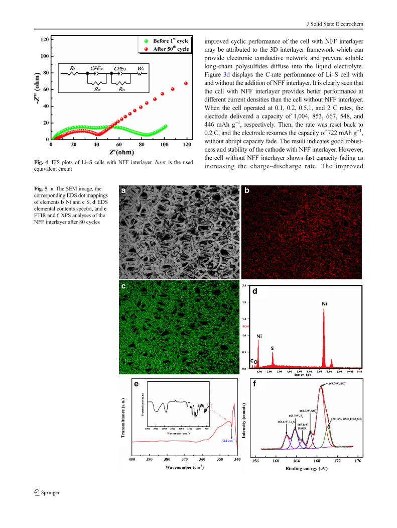
Fig. 5 a The SEM image, thecorresponding EDS dot mappingsof elements b Ni and c S, d EDSelemental contents spectra, and eFTIR and f XPS analyses of theNFF interlayer after 80 cycles
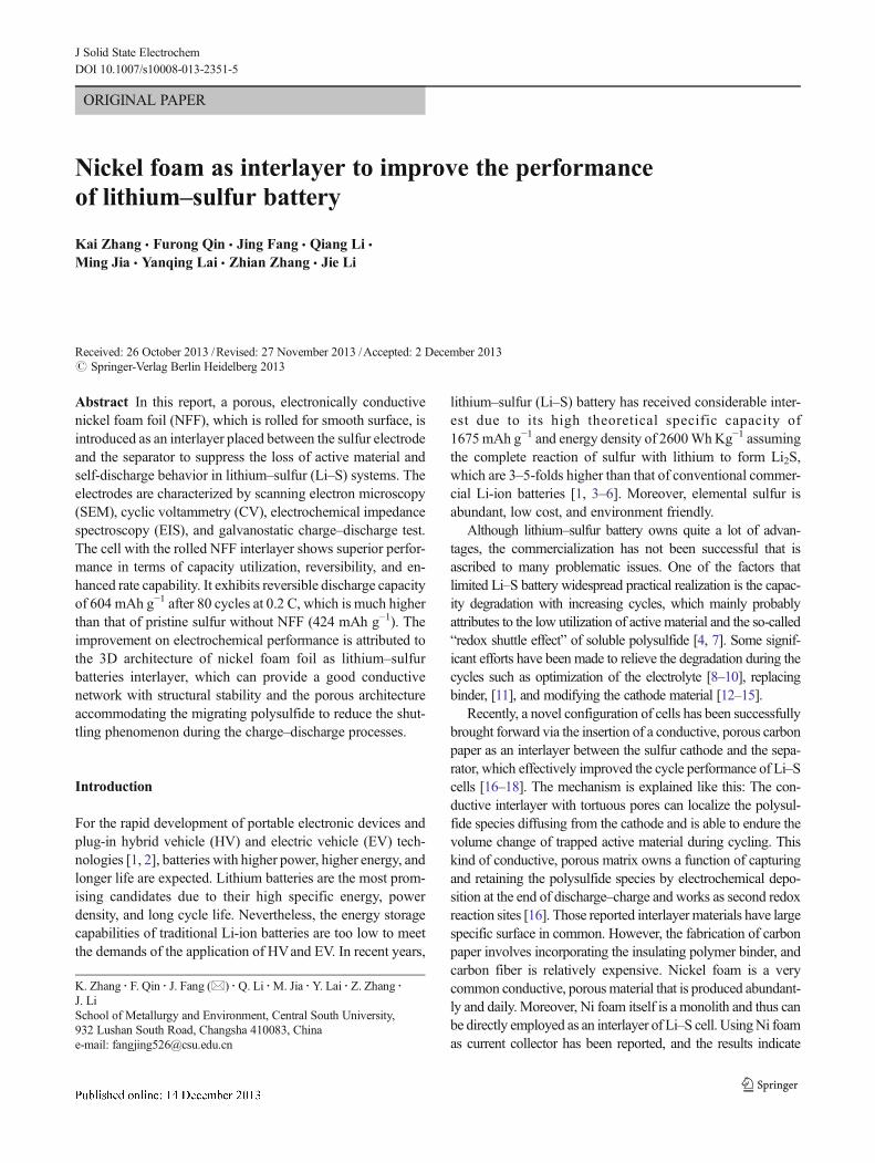
Fig. 4 EIS plots of Li–S cells with NFF interlayer. Inset is the usedequivalent circuit
J Solid State Electrochem
performance of the cell with NFF may be attributed to goodconductivity of Ni foam, which can increase the electronicconductivity of the cathode. Furthermore, the porous Ni foamcan act as a secondary current collector, in which the sulfurspecies are distributed and tightly trapped [19, 20].
The Nyquist plots of the modified cells with the NFF inter-layer before and after cycling are shown in Fig. 4, which arecomposed of two sequential semicircles at high-to-medium fre-quency region and a straight line at low frequency. The Nyquistplots are fittedwith the equivalent circuit as shown in inset Fig. 4.The semicircle at high frequency region corresponds to interfaceimpedance (a parallel connection of R sf and CPEsf), whichreflects the resistance over lithium ion diffusion through thecontacting interface and Li2S/Li2S2 solid film [21]. The semicir-cle at middle frequency region corresponds to charge-transferresistance (a parallel connection of Rct and CPEdl) against theinterfacial electrochemical reaction involved in charge transfer[22]. After cycles, the Rsf decreases apparently from ~40 to ~10Ω, indicating improved interfacial wettability and lithium iondiffusion with cycling. The charge-transfer resistance maintainssteady during cycling (~35–40Ω), indicating stable active sitesfor interfacial electrochemical reaction. It further reveals that thecell with NFF interlayer possesses good electrochemical kinetics,which reflects the good cycle performance of the cell.
After cycles, the cells were disassembled in the argon-filledglove box. The electrodes and the nickel interlayers were rinsedby DME and then dried in the glove box at room temperature.As shown in Fig. 5a, after 80 cycles, the morphologies of NFFinterlayer maintain a stable structure. Precipitates were depos-ited on the interface of the NFF interlayer. As a result of EDSmapping to Ni–sulfur composite, sulfur particles and Ni werewell dispersed in the composite as shown in Fig. 5b, c, whichindicates that sulfur is distributed in the NFF frameworkshomogeneously. In order to ascertain the chemical constituents,EDS spectrum of NFF interlayer before and after cycles wasobtained (Fig. 5d). The strong Ni spectra show that NFF has anexcellent electrical conductivity for long cycles. In order tofurther investigate the functions of NFF interlayer, Fouriertransform infrared spectroscopy (FTIR) (Fig. 5e) and X-rayphotoelectron spectroscopy (XPS) (Fig. 5f) analyses of theNFF after cycling were conducted. As shown in Fig. 5e, adistinguished peak comes out at 344 cm−1, which arises fromthe vibrational peak of Li–S bond. XPS curve of S2p of cycledNi foam (Fig. 5f) indicates various sulfur species on the NFFafter cycling. As like the SEM/EDS results, FTIR and XPSanalyses prove again that the Ni foam can accommodate thesulfur species, which help alleviate the shuttling phenomenon.
Conclusions
In this paper, a porous and conductive commercial Ni foamwassuccessfully introduced as lithium–sulfur batteries interlayer
and significantly enhanced the specific capacities and goodcycling stabilities of the cells. The improvement was due tothe 3D architecture of the nickel foam foil, providing a conduc-tive framework to enhance the active material utilization andstable high-rate battery performance with long cycle life,blocking the polysulfide intermediates from shuttling betweenthe cathodes. In addition, the NFF offers the advantage ofserving as an excellent Ni matrix to retain and accommodatesome of the stress and volume expansion during discharge ofsulfur. This design for the lithium–sulfur battery has a certainimprovement in the commercial application in the future.
Acknowledgments We gratefully acknowledge the financial support ofthe Excellent Youth Foundation (13JJ1003) of Hunan Provincial Scienceand Technology Department, National Natural Science Foundation ofChina (Grant No. 51222403), and Fundamental Research Funds for theCentral Universities (Grant No. 2012QNZT023) of China. We also thankthe support of the Engineering Research Center of Advanced BatteryMaterials, the Ministry of Education, China.
References
1. Armand M, Tarascon J-M (2008) Nature 451:652–6572. Bruce PG, Freunberger SA, Hardwick LJ, Tarascon J-M (2012) Nat
Mater 11:19–293. Xiong S, Xie K, DiaoY, HongX (2014) J Power Sources 246:840–8454. Zhang SS (2013) J Power Sources 231:153–1625. Jin B, Kim J-U, Gu H-B (2003) J Power Sources 117:148–1526. Deng Z, Zhang Z, Lai Y, Liu J, Liu Y, Li J (2013) Solid State Ionics
238:44–497. Bao W, Zhang Z, Qu Y, Zhou C, Wang X, Li J (2014) J Alloys
Compd 582:334–3408. Agostini M, Aihara Y, Yamada T, Scrosati B, Hassoun J (2013) Solid
State Ionics 244:48–519. Xiong S, Xie K, Diao Y, Hong X (2012) Electrochim Acta 83:78–86
10. Chang D-R, Lee S-H, Kim S-W, Kim H-T (2002) J Power Sources112:453–460
11. Sun J, HuangY,WangW, Yu Z,WangA, Yuan K (2008) ElectrochimActa 53:7084–7088
12. ZhouX, Xie J, Yang J, ZouY, Tang J,Wang S,Ma L, LiaoQ (2013) JPower Sources 243:993–1000
13. Lee KT, Black R, Yim T, Ji X, Nazar LF (2012) Adv Energ Mater 2:1490–1496
14. Moon S, Jung YH, Jung WK, Jung DS, Choi JW, Kim DK (2013)Adv Mater DOI: 10.1002/adma.201303166
15. Rao MM, Song XY, Cairns EJ (2012) J Power Sources 205:474–47816. Su YS, Manthiram A (2012) Chem Commun 48:8817–881917. Su YS, Manthiram A (2012) Nat Commun 3:1166–117118. Zu C, Su YS, Fu Y, Manthiram A (2013) Phys Chem Chem Phys 15:
2291–229719. Chung S-H, Manthiram A Electrochim Acta 107:569-57620. Barchasz C, Mesguich F, Dijon J, Leprêtre J-C, Patoux S, Alloin F
(2012) J Power Sources 211:19–2621. Deng Z, Zhang Z, Lai Y, Liu J, Li J, Liu Y (2013) J Electrochem Soc
160:A553–A55822. Kolosnitsyn V, Kuzmina E, Karaseva E, Mochalov S (2011) J Power
Sources 196:1478–1482
J Solid State Electrochem