nickel-cadmium cells - nasa · fifth quarterly report for study of process variables associated...
TRANSCRIPT

9:''':
Fifth Ouarterly Report
STUDY OF PROCESS VARIABLES ASSOCIATEDWITH MANUFACTURING HERMETICALLY-SEALED
NICKEL-CADMIUM CELLS
) o m,
/)1-
i i
N Iw
HUH
Z ·
/, 1:: D * ,Hi3 U H ,
,~ c7 en>
By
Lee Miller
I),
i
II,
I,I1
EAGLE-PICHER INDUSTRIES, INC.ELECTRONICS DIVISIONCOUPLES DEPARTMENT
JOPLIN, MISSOURI64801
MAY, 1972
Covering PeriodMarch, 1971 through May, 1971
PREPARED FOR
NATIONAL AERONAUTICS AND SPACE ADMINISTRATION
GODDARD SPACE FLIGHT CENTER
GREENBELT, MARYLAND 20771
Reproduced by .
NATIONAL TECHNICALINFORMATION SERVICE
U S Deportment of CommerceSpringfield VA 22151
)D'
1.
. .
https://ntrs.nasa.gov/search.jsp?R=19720022380 2018-09-18T08:07:27+00:00Z

NOTICE
This report was prepared as an account ofGovernment-sponsored work. Neither the UnitedStates, nor the National Aeronautics and SpaceAdministration (NASA), nor any person action onbehalf of NASA:
a. Makes warranty or representation, ex-pressed or implied, with respect to theaccuracy, completeness, or usefulnessof the information contained in this report,or that the use of any information, appa-ratus, method, or process disclosed inthis report may not infringe privatelyowned rights; or
b. Assumes any liabilities with respect tothe use of, or for damages resulting fromthe use of any information, apparatus,method, or process disclosed in this re-port.
As used above, "person acting on behalf ofNASA" includes any employee or contractor ofNASA, or employee of such contractor, to the ex-tent that such employee or contractor of NASA, oremployee of such contractor prepares, dissemi-nates, or provides access to any information pur-suant to his employment with such contractor.
Requests for copies of this report should bereferred to:
NATIONAL AERONAUTICS & SPACE ADMINISTRATION/SCIENTIFIC AND TECHNICAL FACILITYPOST OFFICE BOX 33COLLEGE PARK, MARYLAND 20740

FIFTH QUARTERLY REPORT
FOR
STUDY OF PROCESS VARIABLES ASSOCIATEDWITH MANUFACTURING HERMETICALLY-SEALED
NICKEL-CADMIUM CELLS
BY
LEE MILLER
COVERING PERIOD
MARCH, 1971 THROUGH MAY, 1971
CONTRACT NUMBER NAS5-21159
GODDARD SPACE FLIGHT CENTER
CONTRACTING OFFICERJ. A. MALONEY
TECHNICAL MONITORFLOYD E. FORD
PREPARED BY
EAGLE-PICHER INDUSTRIES, INC.ELECTRONICS DIVISIONCOUPLES DEPARTMENTJOPLIN, MISSOURI
64801
FOR
NATIONAL AERONAUTICS AND SPACE ADMINISTRATIONGODDARD SPACE FLIGHT CENTERGREENBELT, MARYLAND 20771
1v

ABSTRACT
The following report describes the effort and results of the
fifth quarter period of a program to determine and study the critical
process variables associated with the manufacture of aerospace, hermeti-
cally-sealed, nickel-cadmium cells. During the period, the impregnation/
polarization process variable study was brought to a close with the com-
pletion of a series of related experiments. The results of the experiments
are summarized as follows:
(1) A scanning electron photomicrographic examination of impregnated
plaques revealed a significant difference in the physical configu-
ration of the impregnated-active materials between positive and
negative plaques and with different process conditions.
(2) A mechanical strength test of impregnated plaques using high levels
of free acid (HN03) in the impregnation solution indicated the nickel
matrix of the plaque was attack by the acid and resulted in a sub-
sequent loss in strength.
(3) The cathodic polarization of impregnated plaques (to precipitate the
active hydroxide form of material) in a caustic solution of KOH re-
sulted in severe blistering of the plaque surface. This phenomenon,
however, did not occur under the same conditions when NaOH was used
as the caustic media. An experiment was devised to measure the volume
and rate of gas evolved in the two processes. The results permitted
the postulation the mechanism involves a high gas generation reac-
tion deep within the nickel matrix of the plaques during the initial
phase of polarization unique to the KOH solution.

(4) A semi-quantitative spectrographic analysis of impregnation/
polarization process solutions indicated impurity levels increase
with repeated solution use (mainly Ni and Cd from the slight
solubility of the nickel plaques and the active materials).
Within the limited number of experiments performed, the increase
did not appear to be a serious problem.
During the subject period, a general characterization of cell
separator materials was initiated. The major conclusion resulting from
the characterization of materials is as follows:
(1) Scanning electron photomicrographic examination of the materials
revealed that a micropolypropylene material (Hercules 'Microweb!")
exhibited distinct physical differences from other materials
tested.
(2) Chemical analysis for the extractable organic content demonstrated
that nylon separator materials possessed more extractables than the
polypropylene separator materials.
(3) A chemical analysis for the inorganic contents of the separator
materials showed Pellon 2505 (Pellon Corporation) material exhi-
bited an unusually high Zn impurity level.
ii

TABLE OF CONTENTS
ITEM DESCRIPTION PAGE NO.
I INTRODUCTION . . . . . . . . . . . . . . .... 1
A. Background 2
II CONTINUATION OF IMPREGNATION/POLARIZATION STUDY. 5
A. Scanning Electron Micrographic Analysis 5B. Mechanical Strength Test 31C. Polarizing Agent Study 37D. Spectrographic Analysis of Impregnation/
Polarization Solutions 43
III SEPARATOR MATERIAL STUDY . . . . . . . . . . 52
A. Scanning Electron Photomicrographic Examina-tion 54
B. Extractable Organic Content & IR Analysis 67C. Inorganic Content Analysis 73D. Separator Study Summation 77
IV CONCLUSIONS AND RECOMMENDATIONS. . . . . . . 79
REFERENCES 83
APPENDIX A 84APPENDIX B
DISTRIBUTION LIST 92
iii

TABLE OF CONTENTS (CONTINUED)
LIST OF TABLES
NUMBER DESCRIPTION PAGE NO.
I SEPARATOR MATERIAL AS RECEIVED FROM VENDOR 68II WET CHEMICAL ANALYSIS (PPM) 74
III IGNITION ANALYSIS 75IV SEMI-QUANTITATIVE SPECTROGRAPHIC ANALYSIS (PPM) 76
LIST OF FIGURES
FIGURES DESCRIPTION PAGE NO.
1 BENDING JIG 322 MECHANICAL STRENGTH TEST 34
Pos. Plaque Experiment No. 5A3 MECHANICAL STRENGTH TEST 35
Pos. Plaque Experiment No. 6A4 SYSTEM FOR MEASURING GAS EVOLVED DURING 38
POLARIZATION5 INFRARED SPECTROGRAM, METHANOL EXTRACTION 706 INFRARED SPECTROGRAM, CARBON TETRACHLORIDE 71
iv

I. INTRODUCTION
The objective of this program is to develop a process procedure
and control for manufacturing nickel-cadmium aerospace cells with reliable
five (5) year life capability. In order to achieve these objectives, each
component part will be investigated separately and collectively to determine
the critical variables and related interactions.
The total program consists of four (4) distinct, yet interrelated
phases. The first phase consisted of a detailed analysis of our procedures
in conjunction with a review of pertinent literature of nickel-cadmium
batteries to assess critical variables of the various processes that affect
cell performance. The second phase will involve the evaluation and testing
(verification) of the variables and their interrelation as determined in
Phase 1. This will include a design of experiments to experimentally
identify critical variables and to establish tolerances required for uni-
form performance. Phase 3 includes the detailed preparation of a Quality
and Reliability assurance Program, Acceptance and Manufacturing Flow Sheets
and a complete hardware specification that can be practically implemented
in a cost effective manner. This specification will be patterned after
"S-716-P-23, Interim Model Specification for High Reliability Nickel-Cadmium
Spacecraft Cells." The Fourth Phase of the program will be to implement
the results of Phases 1 through 3 on a production basis. This effort
will "prove out" the conclusions and will establish both validity of con-
cept and applicability to production equipment and overall operational
capability. During this phase, the deliverable items of separation,
positive and negative plates will be prepared. Also, 20 nickel-cadmium
cells of 20 ampere-hour size will be manufactured to the developed procedure.
Inspection levels will be 100% minimum and complete traceability maintained.
-1-

A. Background
The first quarter of this program was devoted to investigating
the dry-sintering process used in manufacturing porous nickel plaque.
A factorial experiment was designed to examine the sintered plaque character-
istics as a function of the process variables. The data gathered from this
experiment were analyzed using a step-wise multiple regression technique
designed for use with the IBM 1130 computer. At the completion of analysis,
plaques with different characteristics were selected for use in the impreg-
nation factorial experiment.
The second quarter's work encompassed additional variability
analyses of the data from the unimpregnated plaque experiments. This
effort included the prediction of the variability of the plaque manufactu-
ring process within the normal tolerance range of the equipment and was
instrumental in determining the critical variables and their effects upon
the process for the purpose of instituting new control limits. This was
followed by a short production run of three (3) different types of plaques
(high strength-low porosity, average strength-average porosity and low
strength-high porosity). These plaques are being used for the impregnation
studies of the experimental program. Also during the second quarter,
major effort was directed toward the setting up of a separate facility
for the impregnation, polarization, formation, washing and other items
related to the cell assembly for the contract. An experimental program
was designed to study impregnation, polarization, formation and washing.
During the second reporting period, work began on the preparation
of specifications for separator, ceramic-to-metal seal cover assembly and
unimpregnated plaque manufacturing control.
-2-

The third quarterly period included an investigation (strength
tests and scanning electron micrographic analysis) of the properties of
the three groups of sintered plaques produced for use during the impreg-
nation/polarization study. This effort revealed an anomalous group of
low strength which was attributed to a high sintering temperature in con-
junction with a strong sintering furnace reducing atmosphere. This investi-
gation also revealed a plaque group exhibiting characteristic highly de-
sirable in a nickel-cadmium cell plaque; this included high strength and
a very uniform distribution of the porous void.
The experimental data resulting from previously performed impreg-
nation/polarization design experiments was analyzed to determine the effects
of certain process variables which were selected for investigation in the
present process study. This information was used during the following
period to reduce the number of process variables considered for study in
the new impregnation/polarization design experiments.
Preliminary drafts of Quality Assurance Specifications for
sintered nickel plaques, separator materials, and ceramic-to-metal seals
were also completed during this period.
The fourth quarter period of the program was devoted to the
implementation and evaluation of the impregnation/polarization factorial
design experiments formulated for the study of the associated process varia-
bles. A linear multiple regression analysis of the experimental data and
the subsequent interpretation demonstrated the critical variables associated
with the process. In addition, the subsequent interpretation permitted
an assessment of the effects of the process variables upon the final product.
The value of the knowledge gained from this phase of the program was sub-
stantiated by incorporation into specifications controlling the present
production process.
-3-

With the completion of the fourth quarterly period which was
originally intended as the last period, it was readily evident that
many of the original program objectives had not been obtained. In
view of'this difficulty, the program running time was extended result-
ing in subsequent quarterly periods.
The following report summarizes the efforts and results of
the program during the fifth quarter period. The first section describes
four tests which are a continuation of and the completion of the impreg-
nation/polarization proven variable study. The tests include:
(1) A scanning electron photomicrographic analysis of impregnated
plaques to determine physical characteristics.
(2) A mechanical strength test of impregnated plaques to determine
the effects of the use of high free acid levels in impregnation.
(3) A study of the mechanism which results in the more destructive
effect upon impregnated plaques with the use of KOH or a polari-
zing media.
(4) A semi-quantitative spectrographic analysis of impregnation/polari-
zation process solution to evaluate the impurity level changes
with repeated use of the solutions.
The final section of this report introduces a new phase in the
process control study program. The initial work in a study of cell
separator materials is undertaken with an attempt to characterize a
selection of the available materials. The preliminary characterizations
process includes a scanning electron photomicrographic analysis for
physical attributes, and a series of chemical analyses for organic and
inorganic contents.
-4-

II. CONTINUATION OF IMPREGNATION/POLARIZATION STUDY
A. Scanning Electron Micrographic Analysis
Selected positive and negative impregnated plaques resulting
from the previous impregnation/polarization process study (see
Section II of the Fourth Quarterly Report( l )) were subjected to
a scanning electron micrographic analysis. The purpose of this
analysis was an attempt to gain comparative knowledge concerning
the active material distribution in the pores of the sintered
nickel plaques, the remaining porosity of the impregnated plaques,
and the general overall quality of the impregnation as associated
with the various impregnation/polarization process conditions.
All impregnated plaques included in this phase of the study were
processed through completion of the formation operation and may
be considered in a state ready for fabrication into cells.
A plaque was selected from each of the following positive
impregnation/polarization experiments (individual experiments which
constitutedthe design experiments described in the previous Quarterly
Report) for analysis. The reasons for their selection are also
stated below. A complete definition of the process conditions or
levels associated with each experiment may be found in Appendix A
of this report.
1. Experiment Number One - (Micrographs 1, 2 and 3) - This
experiment was selected because the plaques produced
exhibited the roughest surface of all the experiments.
- 5 -

Major Process Conditions:
(a) Impregnation Temperature - 150°F
(b) Impregnation Time - 1 Hour
(c) Free Acid Content (Nitrate Solution) - 1 gm/liter
(d) Impregnation Under Vacuum - Yes
(e) Polarization Time - 1 Hour
2. Experiment Number 5A - (Micrographs 4, 5, and 6) - This
experiment produced the best appearing plaques (smooth,
clean surfaces) of the experiment performed.
Major Process Conditions:
(a) Impregnation Temperature - 200°F
(b) Impregnation Time - 1 Hour
(c) Free Acid Content - 1 gm/liter
(d) Impregnation Under Vacuum - No
(e) Polarization Time - 1 Hour
3. Experiment Number 6A - (Micrographs 7, 8 and 9) - Plaques
exhibiting the greatest active material electrical effi-
ciency wereproduced by this experiment.
Major Process Conditions:
(a) Impregnation Temperature - 200°F
(b) Impregnation Time - 1 Hour
(c) Free Acid Content - 4 gms/liter
(d) Impregnation Under Vacuum - No
(e) Polarization Time - 1 Hour
- 6 -

4. Experiment Number 9B - (Micrographs 10, 11 and 12) -
This experiment was selected because it was similar
to the above three experiments with the exception of
a much shorter polarization time.
Major Process Conditions:
(a) Impregnation Temperature - 200°F
(b) Impregnation Time - 1 Hour
(c) Free Acid Content - 1 gm/liter
(d) Impregnation Under Vacuum - No
(e) Polarization Time - 15 Minutes
A plaque was also selected from each of the following negative
impregnation/polarization experiments for analysis. A complete
definition of process conditions or levels associated with each
experiment may be found in Appendix B of this report.
1. Experiment Number 2 - (Micrographs 13, 14 and 15) -
Plaques produced by the negative experiments did not
exhibit the physical appearance differences that are
associated with the positive experiments; this experi-
ment and the following were selected because of their
similarity in process conditions with the exception of
polarization time.
Major Process Conditions:
(a) Impregnation Temperature - 150°F
(b) Impregnation Time - 1 Hour
(c) Free Acid Content - 0.5 gm/liter
(d) Impregnation Under Vacuum - No
(e) Polarization Time - 15 Minutes
- 7-

2. Experiment Number 3 - (Micrographs 16, 17 and 18) -
Major Process Conditions:
(a) Impregnation Temperature - 150°F
(b) Impregnation Time - 1 Hour
(c) Free Acid Content - 0.5 gm/liter
(d) Impregnation Under Vacuum - No
(e) Polarization Time - 1 Hour
The following photomicrographs are the result of the above
analysis. Normally, three (3) shots are taken of each plaque
sample of increasing magnification (1250X, 2500X and 5000X).
-8 -

m
5* Tl.lF ^ V
w Jf | § r
Ml ¥ , H >* ^mk. m ; I i l l - ^ ^ ^ ^> t - ^ t » *
MICROGRAPH 1 Positive Plaque Experiment No. 1 - 1250 x Magnification
- 9 -

p'
MICROGRAPH 2 ositive Plaque Experiment No. 1 - 2500 x Magnification
- 10 -

m
V € \ "fc
<
i • '
MICROGRAPH 3
ive Plaque Experiment 1 - 5000 x Magnification

/
•»•>>'' 1
/ 1
r MICROGRAPH 4
Positive Plaque Experiment No. 5A - 1250 x Maginification - 12 -

MICROGRAPH 5 Positive Plaque Experiment No. 5A - 2500 x Magnification

MICROGRAPH 6 Positive Plaque Experiment No. 5 A
- 14 -
5000 x Magnification

MICROGRAPH 7 Positive Plaque Experiment No. 6A - 1250 x Magnification
- 15 -

MICROGRAPH 8
Positive Plaque Experiment No. 6A - 2500 x Magnification - 16 -

JW(t
MICROGRAPH 9 Positive Plaque Experiment No. 6A - 5000 x Magnification
- 17 -

MICROGRAPH 10 Positive Plaque Experiment No. 9B - 1250 x Magnification
- 18 -

MICROGRAPH 11 P o s i t i v e P l a q u e E x p e r i m e n t ^ . 9B - 2500 x M a g n i f i c a t i o n

MICROGRAPH 12 Positive Plaque Experiment No. 9B - 5000 x Magnification
- 20 -

* * m
I* I -
4 ^
• W
# 4 '
^%efc / />
~ #1 I t ' '
MICROGRAPH 13 Negat ive Plaque Experiment No. 2 - 1250 x Magnif ica t ion

am ' ^ W»m Ml ^ ^ ^ M . v. ^ # ^ | * •*•"• S
m ^ ^
K ft]
iWB_ Blip ^^wik ji^^^B
a. i f #" * 1 j Mf l t f l H
' mm * At B b «P"WF iBf' ' k St •*"
r> J%
•
•
*t % MICROGRAPH 14
Negative Plaque Experiment No. 2 - 2500 x Magnification - 22 -

# 4 \
% • '
*
.... 4j * * ^ ^v
MICROGRAPH 15 Negative Plaque Experiment No. 2 - 5000 x Magni f ica t ion
- 23 -

I f 0 *•*> "» •, t
-A %
•
$$«
• v c'
^ *
^s Ar* "^ * w
% f
lM.
1 4
W *
\
##
/ *
It *
• 4
t 4
j i ^ • * * «
MICROGRAPH 16 Negative Plaque Experiment No. 3 - 1250 x Magnification
- 24 -

IK: **"
vg §
|
' n< #
l % < *
• • •• " I I : , . . :
Jto; JIB
% SI
§ %
MICROGRAPH 17 Negative Plaque Experiment No. 3 - 2500 x Magnification
- 25 -
pt f
I

f *
4Vr
••••\ •
» 1 •
fc
^ ^
*m
m
...»
*»*. *
JL' *• 1 H I
in** \ % _JBta^ W
f
S^vJ
3
MICROGRAPH 18
Negative Plaque Experiment No. 3 - 5000 x Magnification - 26 -

Observing the photomicrographs of the plaques fromthe positive
experiments, the most distinguishing feature is the difference
between Experiment Number One (Micrographs 1, 2 and 3) and the
remaining positive experiments. The active material(gray area)
in the plaque of Experiment Number One appears to be much more
recessed and broken up in the nickel matrix (white area) and the
impregnated plaque contains large voids (see Micrograph
No. 1). In contrast, the remaining positive plaques, which
exhibit very similar physical appearances, are much more "filled
in" with little recession and no noticeable large voids. All
plaques are impregnated with approximately the same amount of
active material.
It might be assumed the more porous surface (easier accessi-
bility of the electrolyte solution) of the Experiment Number One
plaque would result in a superior electrical performance, but
in actual electrical capacity testing of the subject positive
plaques in a "flooded" electrolyte condition (see "Single Plate
Capacity Testing", Section V, Third Quarterly Report(2)), the
"filled in" or "caked" appearing impregnated positive plaques
exhibited better capacities and active material efficiencies.
These performances might be reversed in a "starved" electrolyte
condition of a hermetically-sealed cell, but comparative data
is not available.
Observing the photomicrographs of the plaque for Experiment
Number 9B (Micrographs 10, 11 and 12), it is noticed there is
little evidence of the protrusion of the nickel matrix as in the
case of the similar plaques of Experiments 5A and 6A (Micro-
graphs 4, 5 and 6 and Micrographs 7, 8 and 9) respectively.
- 27 -

This phenomenon is particularly noticed in the greater magni-
fication, 5000X, of Micrographs 6, 9 and 12 in which the
active material of Experiment Number 9B (Micrograph 12)
appears to be less recessed into the nickel matrix. The
basic process difference involved in Experiment Number 9B
is its shorter polarization time (15 minutes). This would
indicate that an extended polarization time (1 hour) results
in a compaction effect or an increase in the apparent density
of the active material.
In general, the positive impregnated plaque photomicro-
graphs demonstrate the different impregnation characteristics
which may be obtained by a change in the process conditions;
a more porous, rougher plaque surface (Experiment Number One,
Micrographs 1, 2 and 3) is associated with impregnation using
a low nitrate solution temperature (150°F) under vacuum and
the more "filled in", smoother appearing plaque surfaces are
associated with impregnation using a high nitrate solution
temperature (2000 F) without vacuum (Experiment Number 5A, 6A
and 9B, Micrographs 4 through 12).
- 28 -

Observing the photomicrographs of the plaques from the negative
experiments, there is a readily observed difference in the make-up
of impregnated active material in contrast to that which was observed
in the positive plaques. The active material impregnation of the
negative plaques is in the form of small crystal shaped particles
with a few scattered patches of the "caked" appearing material
associated with the positive plaques. Further observation will also
disclose a difference in the particle size between the plaques of
the two negative experiments selected for this analysis. Again,
the plaques of both experiments exhibit approximately the same
amount of active material impregnation.
The major difference between the experiments is the length
of the polarization time. Negative Experiment Number 2 (Micrographs
13, 14 and 15) utilized a short polarization time of 15 minutes and
as may be observed, the impregnated particles are relatively large
and distinct. Negative Experiment Number 3 (Micrographs 16, 17 and
18), on the other hand, utilized a longer polarization time of one
hour and as may be observed, the impregnated particles are much
smaller. Polarization time appears to have an effect upon the
size and shape of the active material particles in the negative
plates.
Electrically, the finer particle plates exhibited greater capacities
and efficiencies (see Table IV, p. 23, 4th Qtrly. Rpt. (1)), which could
be attributed to the obvious greater surface area. With respect to recom-
bination (oxygen reaction at the negative electrode-necessary in sealed
cells), the plates exhibiting the larger particles might perform
better (more porous surface to oxygen gas), but data is not
available to support this postulation.
- 29 -

In general, the photomicrographs of the negative impregnated
plaque indicates that longer polarization times reduce the size
of the active material particles and improves the electrical
capacity and efficiency of the negative plates.
- 30 -

B. Mechanical Strength Test
During the impregnation/polarization process study (previous
Quarterly Report), it was determined that superior electrical
capacities and active material efficiencies were obtained in
positive plaques impregnated in nitrate solutions containing
high levels of free acid (4 grams/liter, HNO3 ). This phenomenon
was attributed to corrosion of the nickel matrix and the subse-
quent formation of additional active material. An obvious
question then arose as to the effect of this treatment upon
the mechanical strength of the finished plates. The following
section describes an experiment .which determined the relative
mechanical strength of plates from two positive impregnation/
polarization experiments which differed in levels of free
acid used in impregnation.
The mechanical strength of the test samples was determined
by a Four Point Bend Testing Machine described in detail in the
(3)First Quarterly Report (see Section C). Basically, the pro-
cedure consists of punching a two (2) inch by one (1) inch sample
from the test plate (the instrument for performing this task is
also described in the above reference), supporting the test
sample on two outer points and applying a compression load at
two inner points (see Figure 1). A load cell senses the
force applied to the supporting points and permits the determina-
tion of the force required for structural failure of the test
sample.
- 31 -

F 6URE iBENDIN G JIG
- 32 -
I

The experiments selected were positive Experiment 5A
(nitrate solution free acid, 1 gram/liter) and positive Experi-
ment 6A (nitrate solution free acid, 4 grams/liter). The plates
produced in these two (2) experiments exhibited approximately
the same amount of active material pick-up and were processed
under similar variable levels with the exception of the free
acid levels. As both of these experiments were also the subject
of the preceding section, the specific experimental process data
may be found therein.
Figures 2 and 3 present graphically the results of the
mechanical strength tests. The graphs begin at a 0 load level;
then as they enter two (2) points start to bend the test
sample downward in a "U" shape, the pressure or load rises
(downward movement of the recorder trace). Finally, at the
point where the test sample starts to give with the applied
pressure and the load tracing levels off, this is taken as the
point of structural failure of the test sample. Each line of
the recorder paper represents a force of 10 grams. The total
force in grams required to cause structural failure is then
determined by the distance of the recorder deflection. The
stress in.psi may also be calculated by use of the formula
(3)described on Page 13 of the First Quarterly Report.
Two (2) tests were performed on a plate from each experiment. The first
tests on Experiment 5A (see Fig. 2) have resulted in structural failure
values of 340 grams (the 390 value indicated is in error) and
320 grams for an average value of 330 grams. The second tests on Experi-
ment 6A (see Fig. 3) resulted in values of 300 grams and 280 grams.
for an average of 290 grams. In addition, it is observed there
- 33 -

Test #2
Ih ... .- - .. ..L.4- . ..
NEMMTi-1t i 1' !, iI
. -I
t. 1 .A . j . . .i i_, . i~.. .F_ :1iiiI t . ' t ti? .tX 5 1.fl.l'' t . I4 ,1,'i' I''1.~. -Tg
H| V 4 ,.:j I rKl~r j-1,; 11!r .... :'
E g f g g ii;ll~lV-l I;:: 2 I : r
I:. .i ' . , ' .!t_:::I: _ 1~:::Ii:::t!'-'F ~:1:t: .:
'
E 1'' :2
· _ :_ ! ,_ , _ .. 1 ..1 I/ I , I I i 'lI ._-- - ._ - ! . , , .~ii[•~~J! ....
j , , : , ,.. i
... .i . . ....... ! ....
_ :-- i ·-..... .... -
!I _: i :- 'it
[i-. 1:] 1 i .. i
:1-l 1. . 2_IL4---|- --,--, !-
II'~~~~I' _ os .ni - j .i.:· i-. , t S I
''''-1, ' . ; }
. l } |\,,,; . .... . ,§~~i--- ·
G7-i~~~ts'\; I~
C--! r T
.. L: .2II .. :i w..+--1 -e- ,- =L;,>&i -'---.- :~ ~i i I I . II I . .- . -- . 1. . . 1 I I .g ggUlf14 4-0l1ul trlii f I I I .1 : 1; ; -1 -t ::
ig t10 X 0! f 49 I 10 t t 1 0 1 tirtX ' h | r 0 ' t>; t 2 = 01 , rX~~~~~~~~~~~~~~~~~~~~~~~~~~~~~~~~~~I 1 -- - - !.
FIGURE 2
Mechanical Strength Test
Positive Plaque Experiment No. 5A
- 34 -
........ I I. I,, . i , , ,x .. I;,,,, ., ... - I - - -- I r-i l . ' . i . . . 1 - it,91=1,1'
tl' .1 .. _ '1, .i _ ' ! 1?_ I-,~~~~~~~~~~~~~~- . ; I11.1. 1 t , ~ . -.
I:j _. I i I I
771-
_--
a
T.
444�
i
T. -0 f
4 i !_. i t t
:-~ : t--
I
- . I.. ... | ',-, 1 t., i I j : |;I ' Hlll
Test #1
' 4 4 ;
WE-E~t~t~JF~-i-i i ! I!:
++I -! - - , ,....
.. ] l. II1 '. . ., 1 1'

Test #4
TPT~~~~~~~~~~~~~~~~~~~~~~~~~~~~~~~~~~
C. 4ij 1 - Ti J' j4j - b -
." ...w , .i.i i- . .
-- Z lit M. I [ i I Xti.., ii j i 0 XX ; X tf: ttli~l'0L| } X-+
I ~i11 Ii Li
lj~~~~~~~~~~~~~~~~~~~~~~~~~~~~~~~I
W~~~~~~~~~11 '.3 [j ': - i -- jLt lF- -,!0 1 t ~
tX~~~~~~i 11 2W 3] [
W1~~~~~~~~~~~~[ ; ilj 0t fri
1-i-il~~~~~~~~iii I·I1 [:i-i-li }I jU'
i~~~~~
W~~~~~~~~ fri tj74i 11'-
_u....,~~~~~~~~~~~~~~~~~~~~~~~~~~~~~~~~~~~~~~~~~~~ . I ·._ i -J.
Test #3
FIGURE 3
Mechanical Strength Test
Positive Plaques Experiment No. 6A- 35 -
i ,ll 1:~~~~-'
1 i 1 I ll, ; ¸
I I1-
'1 . -~~~~~~...... ... .. -.......xrsl;Em~~ ··
-1141{1-144e1S{[11{i ------ ~ eegli ----- (lgil [S [1
----------
--- --- 4! .
,Etulf~l~lllllllllllllAl I mmlllillllllllllllllllliif~uTt~
------- ----- -------------11 1 1 1
- S --1 - - ----- ------
sc:~~ ~~ ~ ~ ~ ~ ~ ~ ~ ~ ~ ~ ~ ~ ~~ ~ ~ ~ ~ ~ ~ ~~~~~~~~~~~~~~~ - - - - -- - -- - --- - -- - - -- - -- --- - -- -- -- -
!,~~~ ~ ~ ~ ~ ~~~~~~~~~~~~~~~~~~~~~~~~~~~~~~~~~ -_ - - --_. -
JIf '
I i f 040" I
i
I, L i1!!H '
~~--------------- - -I . - - -F- -- I; I i
- - . _ O . ! .- _ _ _ _ _ .J
I'' .
I
i
I
-: ''1-
Zt 1f II i ll

is a sharp increase in the load associated with the leveling
points in the recorder tracings for Experiment 6A. This is
the result of the movable portion of the Bend Tester fixture
coming in contact with the stationary portion (see Figure 1).
Experiment 6A test samples bent further into the "U" shape
before achieving structural failure than Experiment 5A and
almost exceeded the movable limit of the test fixture.
It would appear that the impregnation of positive plaques
in nitrate solutions of high free acid levels does result in
attack on the nickel matrix and subsequent loss of mechanical
strength. But, in this case, it was not excessive and amounted
to approximately a 10% loss. The impregnated plaques were, in
any case, significantly stronger than the corresponding unimpreg-
nated plaques. Tests performed on samples of the unimpregnated
plaque lot used in the above experiment resulted in structural
failure values in the order of 200 grams.
- 36

C. Polarizing Agent Study
It was observed during the previous impregnation/polarization
experiments that polarization (conversion of impregnated mate-
rial within the sintered nickel plaque to the active material
form) in a KOH caustic solution resulted in a much more destruc-
tive effect upon the impregnated plaques (flaking of sintered
nickel and active material, see Figures 2 and 3 of the Fourth
(1)Quarterly Report) than polarization in a NaOH caustic solution.
This phenomenon occurred under similar process conditions which
included identical polarization current rates, identical solution
specific gravities, identical polarization times and identical
solution temperatures.
The only force associated with polarization process which
it is believed could effect the observed plaque destruction,
is the evolution of gas during the conversion reaction. To
characterize the gas evolved between the two processes, an experi-
ment was devised to measure the volume and the rate of gas evolved
with caustic media as the single variable.
The physical test setup used in the experiment is shown in
Figure 4. The procedure involved the identical impregnation of
two plates ( 2 2.6" x 2.6" x 0.030" plates were immersed in a solution of
nickel nitrate for one hour) which were then used as test standards.
In the first half of the experiment, one of the impregnated plates
was placed in the sealed plastic container and a solution of
NaOH caustic was introduced. A four ampere polarizing current
was passed for ten minutes; the gas evolved then passed through
the connecting tube-and displaced a certain volume of water in
the graduated cylinder.
- 37 -

IN )N"
-38
-
j4r~C.)' ~-qj
P-4
Ci)
I

The following results were recorded for the experiment:
VOLUME OF WATER DISPLACED
TIME EXPERIMENT #1 EXPERIMENT #2(MINUTES) (NaOH) (KOH)
0 O ml O ml
5 50 ml 80 ml
10 130 ml 160 ml
It is apparent from the test results that a greater volume of
gas was evolved during the experimental polarizing process in the
case of a KOH caustic solution. Approximately 80 ml of gas was
evolved in the first five minute interval as compared to 50 ml
of gas for the NaOH caustic solution. During the second five
minute interval, both experiments evolved equal volumes of gas
(80 ml in both cases). It would appear that the mechanism evolved
in differentiating the two caustic media occurs during the initial
phase of the polarizing process.
It is assumed that the gas evolved affects plaque destruction
by first being trapped in the recesses of the porous sintered
nickel plaque, expanding by further evolution with a subsequent
increase in pressure, and finally breaking up of the sintered
nickel matrix to escape. The word "trapped" used in this explana-
tion may be interpreted as referring to a situation in which gas
cannot escape from an area at a rate great enough to support its
evolution and thus resulting in increased pressure. With this
assumption, an explanation is available to explain why polarization
in KOH with the greater gas evolution results in a more destructive
environment for the impregnated plaques.
- 39 -

A postulation of the exact mechanism which results in the
different volumes of evolved gas must take into consideration
that the same amount of current was passed in both experiments
and would result in equal volumes of gas being evolved if
dealing with the same gas mechanism. It is probable then two
mechanisms of gas evolution are occurring concurrently at the
impregnated plaque during the polarization process. First, the
desired chemical conversion -
X(NOs)2 + H20 + 8e- -> NH3 + X(OH)2 (4) (1)
X = Ni or Cd
Equation Not Balanced
evolves a molecule of ammonia gas upon the transfer of eight
electrons in the process of converting the impregnated material
to the active material form. The second reaction which is assumed
to beoccurring is the electrolysis of H20.
2H20 + 2 e- -> H2 + 20H- (4) (2)
In this reaction, a molecule of hydrogen gas is evolved upon
the transfer of two electrons.
- 40 -

By Avogadro's Law and the Kinetic Molecular Theory, it is
known that different gases containing the same number of mole-
cules, under the same temperature and pressure occupy the same
volumes. It becomes obvious then the volume of gas evolved in
the two processes in question depends upon the ratio in which
the two reactions are occurring in each process while passing
the same amount of current. If the first reaction predominated
the passage of eight (8) electrons would result in the generation
of one (1) molecule of gas. If, on the other hand, the second
reaction predominated the passage of eight (8) electrons would
result in the generation of four (4) molecules of gas.
To suggest why there may be difference in the ratio of these
two (2) reactions occurring in the two (2) processes, it will be
necessary to visualize a cross-section of an impregnated plaque.
It is observed the impregnated material does not penetrate evenly
into the sintered nickel matrix; the bulk of the material is
located in the outer portion of the plaque (near the surface).
Proceeding inward, the amount of impregnated material becomes
smaller until it reaches its lowest concentration near the center
of the plaque. It is further suggested the KOH caustic solution
with its low viscosity (relative to the NaOH solution) and unusual
penetrating ability (creeping effect) readily penetrates the inner
areas of the impregnated plaque.
During the initial phases of polarization in a caustic solu-
tion of KOH, reaction of equation No. ( predominates in the outer
portion of the plaque matrix; but deeper into the plaque there is
less impregnated material to support this reaction. The unavailability
of impregnated material enhances reaction of equation No.(2)with its
- 41 -

much greater gas generation capacity. This phenomenon in effect
occurs in the wrong place at the wrong time. The gas is generated
deep in the nickel matrix where it is difficult to escape and the
large X(N03)2 molecules in the plaque pores have not been fully
reduced to the smaller X(OH)2 molecules which tends to further
block the gas from escape.
It is assumed the NaOH caustic solution does not penetrate
the nickel matrix as readily. The reaction of equation No. (1)
predominates until the impregnation material is converted and
until the caustic solution penetrates the inner recesses of the
plaque matrix with the opening of the plaque pores as the results
of the reaction of equation No. (1.
- 42 -

D. Spectrographic Analysis of Impregnation/Polarization Solutions
In the performance of the study of the process variables associ-
ated with the impregnation/polarization process, effort was expended
in an evaluation of the chemical changes occurring in the various
process solutions as they progressed through different stages of
the operation. This investigation included the following:
(1) Determination of the normality of the caustic solution
at the beginning and end of an experiment (wet titra-
tion method).
(2) Determination of the CO3 content of the caustic solution
at the beginning and end of an experiment (double end
point, wet titration method).
(3) Determination of the NH3 content of the caustic after
the first cycle and the end of an experiment (distilla-
tion and titration).
(4) Free acid content (HNO3 ) of the impregnation solutions
at the beginning of each cycle (titration).
The data resulting from the above analyses was presented in the
Appendix of the Fourth Quarterly Report.
In addition to these tests, the process solutions were subjected to a semi-
quantitative spectrographic analysis for major impurities. In the following
tables, the impurities detected are listed; the levels in which
they are present are expressed in parts per million. In an
example where the Experiment Number is preceded by "pre" or
"post", this indicates that the sample for analysis was removed
before performance of the experiment or after its completion.
When no notation is involved, the test sample was removed before
performance of the experiment. The letters "ND" means the element
- 43 -

was not detected during applicable test. The terms "major" and
"minor" indicates the elements are major constituents of the
test sample. Minor indicates theelement which is lesser in con-
centration.
- 44 -

POSITIVE PROCESS IMPREGNATION
ELEMENTS DETECTED
EXPERI-MENT
#3
#5
#6
#9
#10
Fe
35
24
32
38
15
Cu
3.2
3.3
4.5
2.4
2.4
Mg
5.6
5.6
5.6
7.0
7.2
SOLUTIONS, Ni(NO, ),
IN PPM
Si
32
32
35
Co
5000
5000
5000
+5000
+5000
In these series of tests, information concerning
detection of Si was not included in the laboratory
analysis report.
- 45 -
Ca
500
500
500
200
200

z z
l:x~I
z z
zZ
Z
Z
0 0
o zz
ZZ
Z
Z
'I0
0 0
o~ jazzco
o
Fi
AC
0
0) 0
0
o C
Cd)
1'4
cl z
z
C
P 0
0
-46
-

o o
o o
B'I-I
000
mr4
0 0l
Z
s-I I ¢
li
z~-q , 1=
Z
Z
z za
E-4
Iuw
I1I
E- °
u n1
W
1o
U) 1
-4Ocn
0
<
zI
1-4 CwI L
r
lo
o Z
Z
Z
4J
-' r
-I c zr
.L
O
o s-
0 0
GJ m
C
~
O
4
O4
O
-J
-4O
o Z
o
o~O
~l~ rl~
o~r
s -
000
Z
ooo
o U
C
oo
n0
0 0
L
0 0
0 r>
.
E
cw4 1-4
<
.-4
,
o ct
0 0
(12 ·0
U
o
0o o
a) )
U)
4
00 C
E
a)
Da
L
r- a'
l .-I
44aN
-41
P Z
c
W
U
UU
P
r to
a
EA k
a rq
a
w
P
P
4 g4
v PL
P
4
-47
-
Wz0I-IE-4
0zoH-4¢N00-I
RU)
w U)
0 KWHrn

o o
z 0
CI
.--Z
, I) z
o o
PL Z
Ca
ru
zz:I
E- O
0 °
Er
z na4
4
o 0
0 0
0o
0 0
0 0
o 0
0 I'~
0
.- .
.- '
.-. .
.'
z z
o o
0 -
o0
o .0 o
0o
Z-4-4 C..
4,
0 4
o O
0
-It
41 4
-4
8
-
0oCO
zCD
1-4E-4z0 HoJE
-
Nt-I H2cnUn
N00KE-4C
D

Observations concerning the spectrographic analysis:
(a.) Positive Process Impregnation Solutions
1. The high level of cobalt impurity is the result
of an intentional impregnation solution additive.
2. The high level of calcium impurity cannot be
explained, but it is common only to the positive
impregnation solution indicating that it is an
impurity in the raw material itself.
Conclusion - Repeated use of the positive impregnation solu-
tion within the limits of this work (10 experiments, 4 cycles
each experiment) does not appear to result in the build-upof any particular impurity.
(b) Negative Process Impregnation Solutions
1. The high level of magnesium impurity is the result
of an intentional impregnation solution additive.
2. Cadmium is indicated as a major constituent
because the test sample is, of course, cadmium
nitrate.
3. Nickel is a mild impurity initially, but after the
first experiment and exposure of the impregnation
solution to the sintered nickel plaques, the
nickel impurity level increases considerably.
Conclusion - There appears to be a significant
increase in the concentration of nickel with
the repeated use of the negative impregnation
solution. This accumulative build-up may become
detrimental to the negative electrodes.
- 49 -

(c) Positive Process Polarization Solutions
1. As was the case with the negative impregnation
solution, there is an increase in the nickel
concentration associated with repeated use of
the caustic solution during an experiment. The
concentration level increase is considerably
less than that associated with the impregnation
solution.
2. Potassium appears to be a mild impurity which
increases with use of the caustic solution.
This probably results from a small residue of
KOH remaining in the caustic storage tank
(from previous use of KOH caustic solutions)
and also a small residue in the impregnation/
polarization tank.
3. It is readily observed the purity level of the
KOH caustic solution is superior to the NaOH
solution. Calcium was the only impurity detected
in the KOH solution.
Conclusion - There is a build-up in the concen-
tration of nickel and potassium with repeated use
of the caustic solutions, but it is doubtful either
would be detrimental to the final positive electrodes.
(d) Negative Process Polarization Solutions
1. In the negative process, the build-up in nickel is
replaced with a build-up of cadmium. This would
indicate the nickel concentration increase associ-
- 50 -

ated with the positive polarization solution is
not the result of the solubility of the sintered
nickel as was the case in the impregnation solutions.
Nickel was not detected in any negative caustic solution.
The mechanism for impurity build-up in the polari-
zing solution must be the slight solubility of
the impregnated material Cd(NO3 ) 2 in one case and
Ni(NO3 )2 in the other.
2. Potassium is also a significant impurity in the
negative caustic solutions, but there does not
appear to be a pattern in its concentration level
such as a buildup with use. This may be associated
with error in the analysis or unrepresentative
samples removed for tests.
Conclusion - There is a build-up in the concentra-
tion of cadmium with repeated use of the caustic
solutions and high concentration levels of potassium also
exist; but, again it is probable that neither of
these impurities would be detrimental to the
final negative electrodes.
- 51 -

III. SEPARATOR MATERIAL STUDY
The "Process Variable Study" Program has been primarily
concerned, up to this point, with the study of process variables
associated with the raw plaque laying and sintering process, and the
sintered plaque impregnation/polarization operation. The program is,
however, intended to study all major phases of the nickel-cadmium cell
manufacturing process. During this reporting period, a new phase was
introduced with the study of the characteristics of various types of
separator materials.
The type of tests to be used in this characterization process
are defined by Eagle-Picher Industries' Document EP-MS-118, "Non-Woven
Nylon Specification for Nickel-Cadmium Spacecraft Cells" (see Third
Quarterly Report(2)). This document reflects the specific nickel-cadmium
cell separator tests described in the "Interim Model Specification for
High Reliability Nickel-Cadmium Spacecraft Cells", prepared by NASA/
Industry Committee, April 30, 1969. In addition, the present effort
will include a visual characterization of the various separator materials
by scanning electron photomicrographic examination.
The separatormaterial study is intended to serve a dual purpose.
First, the subject separator materials will be characterized as to their
applicability for use in nickel-cadmium power systems. Second, the
characterization tests themselves will be evaluated to determine if they
evolve useful information and merit retention in nickel-cadmium, aerospace
separator material specifications.
Within the time limits of the present reporting period, the
selected separator materials were subjected to only three (3) of the
proposed characterization tests which were as follows:
- 52 -

(a) Scanning electron photomicrographic examination
for physical attributes.
(b) Methanol extraction for soluble organic content
with subsequent IR analysis of extract for major
organic constituents.
(c) Qualitative and quantitative chemical analysis
for inorganic content.
The original scope of work included two (2) separator materials
for study. These were Pellon 2505, a non-woven nylon material supplied
by the Pellon Corporation and "Lyonel" also a non-woven nylon material
supplied by Howard Textile Mills, Inc. However, at the time of perfor-
mance of the above tests, several other types of separator material
samples of interest were available and they were included in this
initial series of characterization tests. The following is a list of
the separator materials included in the present work:
Non-Woven Nylon
1. Pellon 2505; supplied by Pellon Corporation, 221 Jackson
Street, Lowell, Massachusetts 01852.
2. "Lyonel" (unit weight 2 ounces/sq.yard), supplied by
Howard Textile Mills, Inc., 65 West 36th Street, New
York, New York 10018.
Non-Woven Polypropylene
3. FT-2140, supplied by Pellon Corporation.
4. WEX-1242, supplied by GAF Corporation, Industrial Products
Division, Glenville Station, Greenwich, Connecticut 06830.
- 53 -
C-

Special Polypropylene
5. "100% Woven Cloth Polypropylene", supplied by Howard
Textile Mills, Inc."
6. "Microweb" Micropolypropylene, supplied by Hercules
Incorporated, Fiber and Film Department, P. 0. Box 12145,
Research Triangle Park, North Carolina 27709.
A. Scanning Electron Photomicrographic Examination
Samples of the selected separator materials were supplied to
Rocky Mountain Technology, Inc. located in Golden, Colorado for
performance of the scanning electron photomicrographic examination.
The following photomicrographs are the results of this effort:
- 54 -

MICROGRAPH 19 PELLON 2505
250X Magnification - 55 -

w
MICROGRAPH 20 PELLON 2505
750X Magnification - 56 -

MICROGRAPH 21 "LYONEL"
250X Magnification - 57 •

MICROGRAPH 22 "LYONEL"
750X Magnification - 58 -
ft \\
I 9*
^UM
k' W
I %
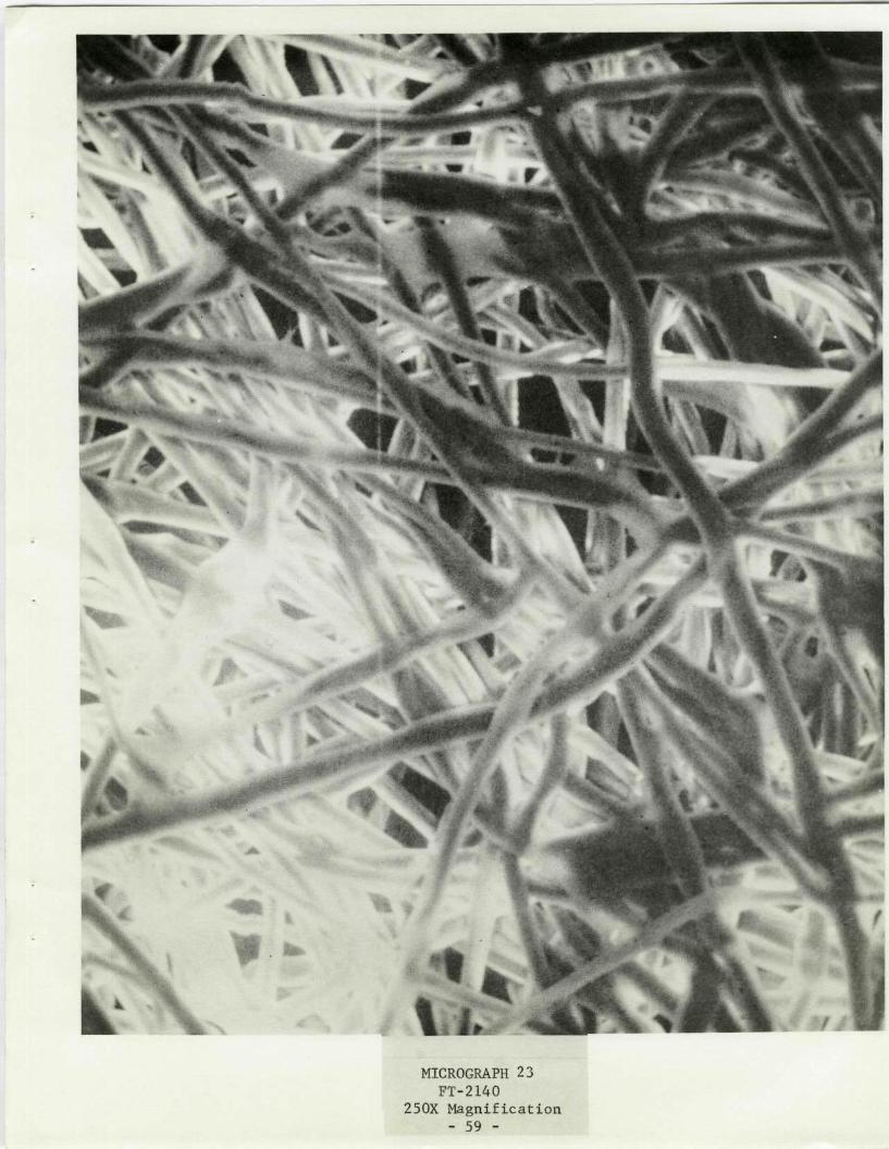
MICROGRAPH 23 FT-2140
250X Magnification - 59 -

k
MICROGRAPH 24 FT-2140
750X Magnification - 60 -

K
I am.
i '
m
»
;< ¥
:i!f:
I ' - # ' '^ - i :, » iV
MICROGRAPH 25 WEX-1242
250X Magnification - 61 -

*i "
\ k »
MICROGRAPH 26 WEX-1242
750X Magnif ica t ion - 62 -
MICROGRAPH 27 "MICROWEB"
625X M a g n i f i c a t i o n

MICROGRAPH 28 "MICROWEB"
625X Magnification - 64 -

MICROGRAPH 29 "MICROWEB"
1250X Magnification - 65 -

• K r * y ' %
MICROGRAPH 30 "MICROWEB"
1250X Magnif ica t ion - 66 -

Observations concerning the photomicrographic study of separator
materials:
1. Individual filament size (diameter) and distribution appear
to be both similar and uniform in both the nylon and poly-
propylene separator materials. The obvious exception is the
"Microweb" separator material. In this case, the individual
filaments vary considerably in size and are poorly distri-
buted through the material (filaments tend to form aggre-
gates leaving open areas).
2. Some form of residue or contamination appears to be associ-
ated with the filaments of the Pellon 2505 separator material
(Note Micrograph 20). This is observed as somewhat of a
ragged edge on a particular filament.
3. Fusion of filaments if observed in the FT-2140 and "Microweb"
materials (Note Micrographs 24 and 30). This phenomenon
occurs to a lesser extent in the WEX-1242 material (Note
Micrograph 26).
4. The "Lyonel" separator material (Note Micrographs 21 and 22)
distinguishes itself by exhibiting not only uniform filament
diameters but also a uniform diameter through the length of
an individual filament. In addition, it exhibits the
cleaner appearing filaments.
B. Extractable Organic Content and IR Analysis
In the following procedure, the extractable organic content
is defined as that portion of a separator material which is soluble
in methanol.
The experiment proceeded with the selection of approximately
a 10 cm squared piece of separator from each material under in-
vestigation with exception of the micropolypropylene which was
- 67 -

not yet available. Each sample was analytically weighed and
then immersed in a beaker containing 100 ml of anhydrous
methanol. The sample was agitated mechanically for 30 minutes
and then the procedure repeated for a second and third beaker
each containing fresh methanol. After completion of this pro-
cess, the samples were carefully dried and reweighed. The
difference in the starting and end weight is expressed as the
percent weight loss or the percent extractable organic content.
The following is a summation of the results of this experi-
ment: TABLE I
Separator Material as Received from Vendor
#1 #2 #3 #4 #5Material Pellon WovenSample 2505 "Lyonel" FT-2140 WEX-1242 Cloth
Wt. Start 0.7039 0.8118 0.7911 0.8368 0.4899(Grams)
Final Wt. 0.6883 0.7943 0.7871 0.8330 0.4864
Wt. Loss 0.0136 0.0175 0.0040 0.0038 0.0035
% Extract 1.932 2.156 0.506 0.454 0.714
The "Lyonel" separator material demonstrated the greater
percent of extractable organic material. This is followed closely
by the second nylon separator material, Pellon 2505. The soluble
contaminant is probably a wetting agent or possibly a residue from
some treatment necessary to the nylon separator manufacturing
process. The polypropylene separator materials demonstrated
significantly less extractable quantities. It would appear the
use of polypropylene materials may result in less contamination
of the cell system from soluble organic materials.
- 68 -

An attempt was made to identify the major organic constituents
of the extraction by IR analysis. An aliquot of the methanol
residue from the first wash beaker for separator material sample
No. 3, FT-2140, was furnished to an independent laboratory
(Bruce Williams Laboratories, Joplin, Mo.) for an IR analysis.
The results of this first attempt were not satisfactory (see
Figure 5). They reported it was not possible to determine the
major organic constituents in the methanol extract, as the effects
of the water of hydration associated with methanol masked the
desired absorption bands.
The laboratory was then supplied a sample of the FT-2140
separator material and they performed their own extraction using
carbon tetrachloride as a solvent. An IR analysis on this extract
rendered distinct absorption bands which could be used for the
purpose of identifying the major organic contaminants (see Figure 6).
The organic contaminants were reported to be similar to a fatty
acid such as soybean oil and linseed oil with a small amount of
amine salts.
In this particular case, the carbon tetrachloride extraction
appeared to be a superior means of identifying the soluble organic
constituents associated with the separator materials. However,
tests would need to be performed to determine if this solvent
attacks the separator material itself before it could be adopted
for the total soluble organic test procedure described above.
- 69 -

SPECTR
UM
N
O.
SAM
PLE
Z AL
CO
I~
~ I
Lu Eut L
0)c
CU
O
~~~~~~u
ol L
u~
~~
~~
~~
~L
Lu
.3 7
O
LU
0 r_
a-
Z
4
p U
Lu
V)
·r u
8

SPECTRUM
N
O.
C
A
A D
i C
l
CCC aCC-
ccCa
LI. i.AL
I-Ccc
000.
C4
-o0CV)
Other investigators have reported success using the methanol
extraction procedure. It may be that in the above extraction,
toQ great a volume of methanol was used for the subject sample size,
resulting in a dilution masking effect of the organic constituents.
The evaluation of this test will be continued with a number
of the remaining separator materials and should render available
additional information for comparison.
- 72 -

C. Inorganic Content Analysis
Three (3) approaches were undertaken to characterize the
inorganic content of the various separator materials. The
first approach involved a wet chemical analysis on extract
aliquots for the following contaminants: nitrate, silica, car-
bonate, nickel, zinc and chlorine. Samples of separator material
were placed in beakers containing 50 ml of distilled water and
magnetically stirred for 16-24 hours. Aliquots for chemical
analysis were then removed.
The second approach involved a complete ignition of the
separator material and the analytical weighing of the remaining
ash. The ash is assumed to consist of the inorganic impurities.
The third and final approach involved a semi-quantitative
spectrographic analysis of the ash resulting from the above pro-
cedure.
In addition to-performance of tests on separator materials as
received from the vendors, samples of the separator materials were
washed in methanol (see extraction procedure above) and the subject
tests performed on the washed samples.
The following tables summarize the data evolved from these
tests.
- 73 -

TABLE NUMBER II
WET CHEMICAL ANALYSIS
(PPM)
SAMPLE CHLORINE NI*
#1 Pellon2505
As ReceivedWashed
TraceTrace
.06
.05
#2 "Lyonel"
As ReceivedWashed
NDND
.05
.05
#3 FT-2140
As ReceivedWashed
NDND
.05
.05
#4 WEX-1242
As ReceivedWashed
NDND
.11
.07
#5 Woven Cloth
As ReceivedWashed
NDND
.20
.05
*Atomic Absorption Method
- 74 -
ZN* NO3 SI02 C03
40.002.10
NDND
NDND
NDND
.24
.22NDND
NDND
NDND
.16
.10NDND
NDND
NDND
.18
.13NDND
NDND
NDND
.10
.16NDND
NDND
NDND

TABLE NUMBER III
IGNITION ANALYSIS
SAMPLE
#1 Pellon 2505
As ReceivedWashed
#2 "Lyonel"
As ReceivedWashed
#3 FT-2140
As ReceivedWashed
#4 WEX-1242
As ReceivedWashed
#5 Woven Cloth
As ReceivedWashed
PERCENT OF STARTING WEIGHT
0.4180.026
TraceTrace
0.012Trace
TraceTrace
Trace0.849
- 75 -

TABLE NUMBER IV
SEMI-QUANTITATIVE SPECTROGRAPHIC ANALYSIS(PPM)
Cs B Mg Si Fe Cu As Zn Ti Ca
#1 Pellon2505
As ReceivedWashed
ND 10 3 50ND ND 3 20
3 1 2 1000 5003 3 5 ND 200
#2 "Lyonel"
As ReceivedWashed
ND100
5 3 20 5 10 2 ND ND 10ND 5 50 3 3 3 ND ND 10
#3 FT-2140
As ReceivedWashed
#4 WEX-1242As ReceivedWashed
ND ND 1 50ND ND 3 100
ND ND 1 ND ND3 1 2 ND 100
ND ND .5 20 ND .5ND ND 5 ND ND ND
1050
1 ND ND 2.5 ND ND ND
#5 Woven Cloth
As Received NDWashed ND
ND 1 20 ND .5 2 ND 500ND .5 10 ND .5 1 ND 50
- 76 -
SAMPLE
3010
302

Reviewing the analytical data presented in the three (3)
tables, the inorganic impurities detected generally appear to
be minor and randomly distributed through the various separator
materials. However, a high incidence of Zn impurity is associ-
ated with Pellon 2505 (Sample #1) in the "as received" state.
This is evidenced in both the wet chemical analysis and spectro-
graphic data. In addition, somewhat higher levels of Ti are
associated with Pellon 2505 (Sample No. 1) and 100% woven cloth
polypropylene (Sample No. 5) materials.
The methanol wash procedure does not appear, in general, to
be effective in reducing the inorganic impurity levels. However,
the Zn impurity level associated with Pellon 2505 (Sample No. 1)
is an exception. The impurity level is significantly reduced by
the treatment as evidenced again in both the wet chemical analysis
and spectrographic data. There is also some evidence of a reduction
in the Ti impurities.
The amount of ash remaining in the ignition analysis appears
to be minor for the samples tested. A peculiar result was en-
countered with the woven cloth (Sample No. 5); the amount of ash
residue increased for some unexplained reason with the methanol
washed sample.
D. Separator Study Summation
Summarizing the effort in the separator material study during
this reporting period, the three (3) tests utilized during this
period (photomicrographic, organic and inorganic analysis) appears
to offer some useful information in the characterization of various
separator materials from an R & D standpoint. However, correlations
between the various parameters measured and the effect upon the
function of the separator material in nickel-cadmium systems would
- 77 -

have to be identified to justify the incorporation of all the
tests in a nickel-cadmium separator material specification.
From a quality assurance standpoint, a number of the
analytical tests merit consideration. A standard separator
material quality level could be maintained by specifying speci-
fic organic extraction, inorganic ignition, and semi-quantitative
spectrographic requirements.
- 78 -
IV. CONCLUSIONS AND RECOMMENDATIONS
1. A scanning electron photomicrographic examination of impreg-
nated positive and negative plaques resulted in the following
observations:
a) Positive and negative plaques are distinguished by the
entirely different appearance of the impregnated active
materials. The positive material presents almost a
continuous mass (broken up by surface cracks) with
little evidence of discrete or crystal shaped particles.
The negative material is just the opposite being made up
of distinct crystal shaped particles.
b) The vacuum impregnation of positive plaques under a con-
dition of low nitrate solution temperatures (150°F)
results in impregnated plaques exhibiting very rough and
porous surfaces.
c) The impregnation (no vacuum) of positive plaques under a
condition of high nitrate solution temperatures (2000 F)
results in impregnated plaques exhibiting very smooth and
non-porous surfaces.
d) Longer polarization times (one hour) used in the positive
plaque impregnation process appears to result in the
greater compaction of the active material into the
sintered nickel matrix of the plaque.
e) Longer polarization times (one hour) used in the negative
plaque impregnation process appears to result in a signi-
ficant reduction of the size of the crystal shaped particles.
- 79 -

2. The positive process impregnation of sintered nickel plaques
in nitrate solutions containing high free acid levels (4 grams/
liter of HN03) results in attack upon the nickel matrix and a
subsequent loss of mechanical strength. The loss, however,
appears to be small, amounting to only 10% of the mechanical
strength of plaques impregnated in nitrate solutions containing
low free acid levels (1 gram/liter).
3. The more destructive effect upon positive impregnated plaques
from polarizing in a KOH caustic solution compared to a NaOH
solution is believed the result of a larger volume of gas
being generated deep in the sintered nickel matrix when using
the KOH solution.
4. A semi-quantitative spectrographic analysis of impregnation/
polarization process solutions resulted in the following con-
clusions:
a) The repeated use of the positive process impregnation solu-
tion (Ni(N03)2) did not result in any measurable build-up
of a particular impurity.
b) The repeated use of the positive process polarization solu-
tion (KOH or NaOH) resulted in the build-up of nickel and
potassium impurity levels.
c) The repeated use of negative process impregnation solution
(Cd(N03)2) resulted in an increase of the concentration of
nickel.
d) The repeated use of the negative process polarization solution
(NaOH) resulted in the build-up of cadmium and potassium impurity
levels.
5. Selected separator materials were subjected to a series of tests
(scanning electron photomicrographic examination for physical
- 80 -

characteristics, methanol extraction for soluble organic content,
and chemical analyses for inorganic content) for the purpose of
characterizing the separator material and evaluating the
particular tests for its applicability to separator material
specifications. The following conclusions evolved from this
process:
Photomicrographic Examination
a) The five (5) separator materials study (two nylons and
three polypropylenes) generally demonstrated uniform
filament size and distribution within a material and from
separator to separator. However, the new Hercules 'Micro-
web" micropolypropylene separator material presented a
radical deviation from the norm with very un-uniform
filament size and distribution.
b) The Pellon 2505 nylon separator material appeared to have
some form of contamination associated with the individual
filaments (evidenced by rough filaments surfaces).
Methanol Organic Extraction
c) The nylon separator materials studied demonstrated greater
extractable organic contents than the polypropylene mate-
rials (typically 2.0% compared to 0.5% of sample weight).
d) In an attempt to determine the major organic constituents
in the methanol extract by IR analysis, very poor results
were obtained. An extraction was then performed in carbon
tetrachloride with significantly improved results.
e) An IR analysis (using carbon tetrachloride as the extraction
media) identified the major extractable organic constituents
associated with the Pellon FT-2140 polypropylene separator
as a material similar to a fatty acid such as soybean oil
or linseed oil.
- 81 -

Inorganic Analysis
f) Significant quantities of Zn impurity (1000 ppm) was
detected in the Pellon 2505 nylon separator material.
In addition, quantities of Ti impurity (500 ppm)
were detected in Pellon 2505 and the 100% woven cloth
polypropylene material.
g) Generally, the washing of separator materials in methanol
does not appear to effectively reduce the inorganic
impurity levels. However, in the case of Pellon 2505, a
significant reduction in the Zn impurity level was ob-
tained by the washing procedure.
6. The various tests utilized in the separator material study
during this reporting period appear to be useful for
characterizing separator materials, but they are not recom-
mended in their entirety for incorporation in cell separator
material specification. Particular analytical tests (organic
extraction, ignition analysis and spectrographic analysis)
could, however, be recommended for quality assurance sections
of the above documents to assure a standard quality separator
material is obtained.
- 82 -

REFERENCES
1) Fourth Quarterly Report, Study of Process Variables Associated With
Manufacturing Hermetically-sealed Nickel-Cadmium Cells, Eagle-Picher
Industries, Inc., Joplin, Missouri, September 1971; prepared for NASA/GSFC,
Contract Number NAS5-21159.
2) Third Quarterly Report, Ibid, June 1971.
3) First Quarterly Report, Ibid, May 1970.
4) Skoog, Douglas A., West, Donald M., Fundamentals of Analytical Chemistry,
Holt, Rinehart and Winston, 1963.
- 83 -

APPENDIX A
- 84 -

EXPERIMENT NUMBER 1
VARIABLE
Specific Gravity of Nitrate
Free Acid (Controlled By Addition of HN03)
Temperature of Nitrate (In I/P Tank)
Time of Impregnation
Vacuum
Wash Time
Wash (Number of Cycles)
Wash Water Temperature
pH of Wash Water (Measured pH Paper)
Type of Caustic
Specific Gravity of Caustic
Temperature of Caustic (In I/P Tank)
Amount of NH3 in Caustic
Amount of CO3 in Caustic
Amount of OH in Caustic
Polarization Current
Polarization Time
Voltage of Plaque to Reference
Amount of Cycles with Same Caustic
Number of Total Cycles
Type of Plaque
LEVEL
1.70
1.0 gms/liter
132 to 137°F
1 Hour
15 Inches
30 Minutes
1 Cycle
59°F
4.5 to 5.3
NaOH
1.30
64 to 74°F
0.021 to 0.037 N
0.2 N
9.2 N
0.4 amps/in2
1 Hour
See Appendix
1 Cycle
4 Cycles
3 Types
- 85 -
1.
2.
3.
4.
5.
6.
7.
8.
9.
10.
11.
12.
13.
14.
15.
16.
17.
18.
19.
20.
21.

EXPERIMENT NUMBER 5A
VARIABLES
As shown for previous
II II *. I!
II .II I II
.. I! II ! .
!! S! !! ;!
;I II !l II
lI II l! ! t
if It !; ; I
!! Ii II If
I IIl II l!
!! ! l II t!
Il II It ! l
If ; If IIl
II If lI ; I
lI !! !! l!
Il lI If If
li ! l II ii
II I; I! II
II !l ft ! l
l; !! ! ! lf
I, II II II
experiments
11
lI
II
11
It
II
11
It
II
II
II
II
II
!l
II
LEVEL
1.70
0.80 to 1.0 gm/liter
178 to 186°F
1 Hour
0 Inches
10 Minutes
3 Cycles
50 to 52°F
4.5
NaOH
1.30
150 to 160°F
0.007 to 0.018 N
0.28 to 0.44 N
9.4 to 9.8 N
0.4 amp/in2
1 Hour
See Appendix
4 Cycles
4 Cycles
3 Types
- 86 -
1.
2.
3.
4.
5.
6.
7.
8.
9.
10.
11.
12.
13.
14.
15.
16.
17.
18.
19.
20.
21.

EXPERIMENT NUMBER 6A
VARIABLE
As shown for
if it if
it ft It
I! ! ! 1o
ft it ot
f[ If ft
ft ft ft
ft 1t ft
ft ft it
of of l
previous experiments
if it
it if
ll It
it it
it to
It if
it of
It 11
it II
it 11
ti if
ft fI
ft ft
LEVEL
1'.80
3.8 gms/liter
182 to 190°F
1 Hour
0 Inch
10 Minutes
3 Cycles
48 to 50°F
4.5
NaOH
1.30
150 to 160°F
0.009 to 0.024 N
0.16 to 0.24 N
9.6 to 9.9 N
0.4 amps/in2
1 Hour
See Appendix
4 Cycles
4 Cycles
3 Types
- 87 -
1.
2.
3.
4.
5.
6.
7.
8.
9.
10.
11.
12.
13.
14.
15.
16.
17.
18.
19.
20.
21.

EXPERIMENT NUMBER 9B
VARIABLE
As shown for
,, It I!
II ! f It
If fi I!
Il f! ;I
tI It If
II I! fl
i! ft If
f! f! I!
If II if
,, fI II
! IIl II
It II It
II It If
,. .. t!
II It it
,I It II
ft f! fI
ft II fI
It If II
II II II
previous experiments
Ft It
It if
II If
I, II
It if
11 Il
II II
II II
II II
it II
II 11
11 it
11 11
II It
I, ItFF FF
,. ...
FV FF
F! FV
LEVEL
1.80
1.0 to 1.2 gms/liter
186 to 190°F
1 Hour
0 Inch
10 Minutes
3 Cycles
49°F
4.5
NaOH
1.30
138 to 156°F
0.012 to 0.014 N
0.32 to 0.36 N
9.2 to 9.5 N
0.4 amp/in2
15 Minutes
See Appendix
4 Cycles
4 Cycles
3 Types
- 88 -
1.
2.
3.
4.
5.
6.
7.
8.
9.
10.
11.
12.
13.
14.
15.
16.
17.
18.
19.
20.
21.

APPENDIX B
- 89 -

EXPERIMENT NUMBER 2
experiments
to
it
it
It
ft
It
if
if
it
II
It
II
it
It
I.
.1
LEVEL
1.90
0.5 to 0.6 gms/liter
132 to 140°F
1 Hour
0 Inches
10 Minutes
3 Cycles
50°F
4.5
NaOH
1.30
78 to 94°F
0.007 N
0.16 N
8.3 N
0.4 amps/in2
15 Minutes
See Appendix
3 Cycles
3 Cycles
3 Types
ft
It
It
- 90 -
1.
2.
3.
4.
5.
6.
7.
8.
9.
10.
11.
12.
13.
14.
15.
16.
17.
18.
19.
20.
21.
VARIABLES
shown for
if tI
II it
If It
it of
It ft
It it
if it
it lt
II if
ft 11
tl If
it ft
It II
to If
II 11
It It
11 11
It II
i 11i
lt if
As
lt
I!
'I
ft
it
II
it
11
lt
it
It
lt
I!
It
.i
It
11
If
it
it
previous
.i
it
it
it
it
ft
ifII
it
II
if
ft
1111
11
ft
II

EXPERIMENT NUMBER 3
VARIABLES LEVELS
As shown for previous experiments 1.80
" " " " " 0.4 to 0.6 gms/liter
" " " " " 130 to 138°F
" " " " " 1 Hour
" " " " " 0 Inches
" " " " " 10 Minutes
I " " " 3 Cycles
,, ,, ,, ,, ,, 48OF
,," " " "l " 4.5
1"1 II II " t "NaOH
t" " " " " 1.30
" " " " " 92 to 103°F
,," " " ,, ", 0.009 N
I" " " i " 0.20 to 0.92 N*
"i i it " d " 9.0 to 9.3 N
I" II " " " II 0.4 amps/in2
It" " " " " 1 Hour
ri" " " " " See Appendix
" " " " " 3 Cycles
I " " " " i" 3 Cycles
it" " " " " 3 Types
*Suspect high carbonate indication is the result of the use ofcarbonate contaminated deionized water.
- 91 -
1.
2.
3.
4.
5,
6.
7.
8.
9.
10.
11.
12.
13.
14.
15.
16.
17.
18.
19.
20.
21.

DISTRIBUTION LIST
GODDARD SPACE FLIGHT CENTER--- eSI-$ S- TA -BRANCH - -..
ADDRES$ LABEL SYSTEMRUN DATE MAR-24-1972
NAXGNAL AEROANO SPACE ADMKN
'S"ETA F~TIC AND TECHNICALINFORMATION CENTER. INPUT
-loWX 0 33-.COLLEGE PARK MARYLAND 207400010 l_
MRo R CHARD LIVINGSTON9CODE MTG
AND JPACE ADMIN.- I .~GT · .sC o 20546
_-4-~~ _- . _ . _. .
MASTER LISTREPORT NO 1932
LIST 020
23 MR ERNST M COHN CODE RPP4 NATIONAL AERO5 AND SPACE ADMIN6 WASHINGTON, D.C. 2054678 0020
I MR. JON RUBENZER, M.S. 244-22 AMES RESEARCH CENTER CODE PBS3 NATIONAL AERO4 AND SPACE ADMINI5 MOFFETT FIELD, CALIF. 9403567
- - -8- 06 0- . -.
MR WILLIAM WEBSTER CODE 761 3 MR FLOYD FORD CODE 761--- NASA--.G D -SPAC.E FLIGHT CEN -4 NASA G.ODARD SPACE .FLIGHT CEN .
GREENBELT MARYLAND 20771 5 GREENBELT MARYLAND 2077167
0084 8 0087
--F- 'JACt '-E' ZAK %S MS 4-8 I MRA. JOH1N L.PATTERSUON CODE 472LANGLEV RESEARCH ENMTER 2 LANGLEY RESEARCH CENtER
X.. . . - ----AF~- ... ... -3 NATIONAL AEROAND SPACE ADEN 4 AND SPACE ADMINHANP7s VERGENEA 23365 5 HAMPTON, VIRGINIA 23365
67
0i _0 8 0120.
DRe Jo SUART FORDYCEe
LEMWS RESEARCH CEINTER3AT8 a AERO
2A000 GROOEPARK ROADCLEYELMDI _OHIO 44135
-- V - "P'GPU$t-O9 LAIDORATORI ES6>300 OAM GR0VE DRIVE
._A..SEDE~A _ O_ RN.A 9[_103.
I MR. CHAS B8 GRAFF S&E-ASTR-EP2 GECO-C. -ARSHALL SPACE FL CEN3 NATIONAL AERO4 AND SPACE ADMIN5 H)NTS-VLLE-E - - ALtABAMA 35812678 0160
1.23 MR. AIJI UCHIYAMA MS 198-2204 JET PROPULSI0N LAABORATORY5 4800 OAK GROVE DRIVE6 PASADENA, CALIFORNIA 91103
8 0190
on YMN KING 1 DR JOSEPH LACKNERDEFENCE R$EEARCH ESTABLISHMENT 2 DEFENSE RESEARCH ESTABLISHMENT
.--. - s-i R- -'CE $- -O-9 Vi S A O' - 3 -POWER SOURCES 'DIVISION-SWALEV RAV 4 SHIRLEY BAY
-_ _-~ .f PQ~T&RO__C AMQDA 5 OTTAWA ONTARIO CANADA6
-~-- ......... 8 0205
UoSo AMV .... t-AT- -AO T-RY2 .
~EEOGV CO1ERSENO 'RESEARCH DIV 3 HARRY DIAMOND LABORATORIESFO¥ 3EL¥ - -v---9V-RG}MI~i-~a-22 -- RQ 1 3 00. _~UILDING 9 N
*WAnY Ra9' 22060. C8NN-E-CTiU AVE. & VAN NESS NW6 WASHINGTON9 D.C. 20438
0220 8 0230
- 92

DR. A. M. GREG ANRUS-CODE SCCNATIONAL AEROAND SPACE ADMINWASHINGTONq D.C. 2054f
23 -DR. E. N. CASE, CODE UT
I-.- -..4-NA-TlONAU--A-d-- .........................6 5 4ND SPACE ADMIN
- .7._6 .ASl.H GlTQN- .- .7
0030 0' 8 0040
MR GERALD HALPERT CODE 764 1 MR. THOMAS HENNIGAN,GODDARD SPACE FLIGHT CENTER 2 CODE 761.2NATIONAL AERO --.. 3 GOODUARD' SPACE--FUIT- t-CENTER --.. - --AND SPACE ADMIN 4 NATIONAL AEROGREENBELTr MARYLAND 2.0771 . .5...A -.SPCE. ML.......
o GREENBELT, MARYLAND 207717
0070
1 MR. LOUIS WILSON CODE 450- - z- C2 UD--R DPF-I cGHT -- T E
MR EUGENE R STROUP CODE 761 3 NATIONAL AERONASA. GODDARD SPACE.. FLIGHT C E ..4ANSP ACE.AL.... .-............ .-........................... _..GREENBELT MARYLAND 20771 5 GREENBELT, MARYLAND 20771
6-7 -- .. . -
0090 8 0100
DR. LOUIS ROSENBLUM, N.S -302---lLEWIS RESEARCH CENTERNATIONAL AERO .AND SPACE ADMIN2100 BROOKPARK ROADC-LEVELAND, OHIO -44135
0130
MR. W E. RICE, EP5..XANNED SPACECRAFT CENE___NATIONAL AEROAND SPACE ADMINHtUSTON, T-EXAS 77058 -
0170-
L M.° HAKVYtY SLCH'ARL, M5 3©(V-1 -2 LEWIS RESEARCH CENTER3-.._I II.C L. _ AtK. ...... ...... ..... _. _ ..............4 AND SPACE ADMIN5 21000 BROOKPARK ROAD6-b-fC-vEtAti, -6.4413,------ -- -78 0140
2
3 MR. DANIEL RUNKLEF MS 198-2204 JETPROPULSION LABOR4TORY-5 -4eB06AK-&i**ef-i-13**RVL ------ --------6 PASADENA, CALIFORNIA 9110378 vUljJ;
· ----- --- L- --2
MR STANLEY J KRAUSE MS 198-220 3 DR. R. LUTWACK, MS 198-220JET- -PROPULSIO -L-A8-UAT-R-IfES- -- -- 4--J-E-T-P -S~N LA.-*H-tRA-T------ -- ----4800 OAK GROVE DRIVE 5 4800 OAK GROVE DRIVEPASA'ENA CALIFORNIA 91103 . _6 PASADENA, CALIFORNIA 91103
0195 8 0200
DR M A STOTT TELESAT CANAOA333 RIVER ROADOTTAWA ONTARIO CANADA
0206
1 MR. NATHAN KAPLAN2 HARRY DIAMOND LABORATORI. ES
- - --3-R--fiBM- -3-e'-,--li-LeDif9t ----- -----------. ...-----------.4 CONN AVE. £ VAN NESS ST.,NW5 WASHINGTON- . . C. 2043 _
78-...... -0210 ....... : ....... . .... .........--.....-.....-.....
U.S. ARMY ELECTRONICS COMMAND 3 bIRECIOR PONER PROGRAMATTNAMSEL-TL-P 4 CODE 473FORT:: MONMOUTH, NEW JER 07703 S OFFTCFF-- NA-VF--RtESEA-ECH-........
6 ARLINGTON, VIRGINIA 22217
0240 8 0255
- 93 -

GOODARD SPACE FLIGHT CENTER MASTER LISTsR UINESS DAT BARANCl .. ....... . ..... NU 1932ADDRESS LABEL SYSTEM LIST 020RUN DATE MAR-24-1972
2MR. HARRY We FOX- CODE 472 3 MR S SCHULDINER CODE' b160
OFFNICE Of NAVAtdESE-J[RCt1- -.-..4-NA- VA -RESEA-RCH--LAB RATORY TARLINGTON, VIRGINIA 22217 5 4555 OVERLOUK AVENUE, S.,W.
.... _.............__...... _6 _ASHIN-GTON,. D.C., 203607
0260 8 0270
-MR EtDt-WIME AIRt-53643NAVAL AIR SYSTEMS COMMAND£1... EPARTMENL Of TiHE NAVY.WASHINGTON D C 20360
12
-3 DR H ROSENWASSER AIR 310C4 NAVAL AIR SYSTEMS COMMAND5 DEPARTMENT OF THE NAVY6 WASHINGTON, O. C. 203607
-8 0290 .-
MR AL HIMY 61570 3 CHEMICAL LABORATORYNAVL_. SHIP ELGLEERIGGCENER ._.4 FLE. L. .. *.
ENTER BLDG, PRINCE GEO CENTER 5 MARE ISLAND NAVAL SHIPYARDHYATTSVILLE, MARYLAND 20782 6 VALLEJO CALIF 94592
0320 8 0325
2_ C [_P_[CKETT. AFAPL/POE-L . 3 MR R. L KERR .POE-i
AERO PROPULSION LABORATORY 4 AF AERO PROPULSION LABORATORYWRIGHT PATTERSON AFB 5 WRIGHT PATTERSON AFB
-- H 43-- -- ------ - -.6-6DAYTON OHIO 454337
0350 8 0360
HQ SAMSO 3 OR JESSE C DENTGN/SMTAE/LT. R. BALLARD/ 4 NATIONAL SCIENCE FOUNDATION
-.---.OS---AEL--ES A-IR FORCE- S-TATION ---I80- G- STREET NW --LOS ANGELES, CALIFORNIA 90045 6 WASHINGTON O C 20550
7039-0 ............................... 8 C 395
2AEROSPACE CORPORATION 3 DR. R. A. HALDEMAN
-- A*-TN-.- L-BRAR-Y---AC-U IS-TION--GR--- -4-AMtERICAN CYANAMID COMPANYP.Oo BOX 95085 5 1937 WEST MAIN STREETLOS ANGELES,_ CALIFORNIA 90045 6 STAMFORD, CONNECTICUT 66902
0410 8 0420
_- .. ....... DR. He L. RECHT2 ATOMICS INTERNATIONAL DIVISION
--- BDR--FRANK--SWiNOELtL -- ----.- ---.3 NORT- AMERICAN AVIAT-UON, INC.ARTECH INC 4 P.O. BOX 3092816 FALLFAX DRIVE 5 CANOGA PARK, CALIFORNIA 91304
----FA. -S - CHURCH-VIRGINIA -Z" 20-42 -6 7
-R. -- O4. ....-. . 8E E --2-440
-2-MR. D. O. FEDER 3 MR R L BEAUCHAMPBELL TELEPHONE LABS INC. 4 BELL TELEPHONE LABORATORIES
-UR-U AYT-HtILL¥-,-NEW JERSEY 07974 5 MURRAY HILL-NEW JERSEY 079406
0480 8 0485
- 94 -

MR JOE YUEN CODE 7975-NA`VA-t -RESE-ARCH -t XaOlT OR-t4555 OVERLOOK AVENUE SW
. ASHNGT ON.... D... C... 2.03 60_
0275
-COMMANDING OFFICERNAVAL AMMUNITION DEPOTMR D G MILEY CODE 305CRANE, INDIANA 47522
--C300 ......
MR. ROBERT E. TRUMBULE, S43_1. SUI.TLAND PRAD..SUITLAND, MARYLAND 20390
-A- -23 MR. J. H. HARRISON, CODE A731~-- NL-~- -S~--r--t LAtR 4Tf'--Y5 ANNAPOLIS, MARYLAND 21402
78 0280
12
- .---. 3- MK-.--P-LIP- '-'';CL-E-i. -tt CtYE-' - Z-Z.--------4 NAVAL ORDiNANCE LABORATORY5.. SI LVER__.. SPR.N._, ._MARYLAN _..2.Q. l......67
......... ____ _
/I
TIC 3 MR,. b/G. RfjSENBAUM, CO!rE 23422....... ..4.._NAY_ ST P.S_~T '1_,SI X t_ __AI.. . _
5 IASIINGTTiN, D.C. 203606 9.
_7___ ___
0330 8 -o0o
MR EDhiARD RASKIND LCC W 1 NG F j M.R RANK J.M__O.URA.A._. ......................AF CAM8RIDGE RESEARCH LAB ,'4 ROME AIR DEVELOPMENT CLNTERL G. GHANSCOM FIELD /` 5 GRIFFISS AF8, NEW YORK 13440BEDFORD, MASSACHUSETTS- -O-31--- --- 6 .....- --............ ----........... --..........
' 70370 ' 8 0380
DR. W. J. HAMERNATIOGNAL BUREAU OF STANDARWA-SHINGTON, -D.C. 2-023-4 ,- --
..0400
I I1
3 MR LARRY GIBSON.DS 4 AEROSPACE CORP---- -- P----- - --------- - -- ----------- -- .
6 LOS ANGELES CALIFORNIA 900457
.. 8. ... .-- ---- -"-0
.__. . I .... ._...T.. ..__DET__.R..IL~.0J~EY ________2 CHEMISTRY DEPARTMENT
MR. R. A. KNIGHT 3 AMERICAN UNIVERSITY-AMF---I NCORPORA T E -A- ---- - -- ------ 4- A---A ---- A--A-V'- ~--..----. --- ---- ----.689 HOPE STREET 5 WASHINGTON, D.C. 20016STAMFORD,.. CONNECTICUTT 06907 6
0425 8 0430
2,.kR, R, F, F"GLE!G-18 -3 -GF-J . ...-I .... - ---i--- -AUTONETICS DIISION, NAR 4 BATTELLE MEMORIAL INSTITUTEP.O. BOX 4181 5 505 KING AVENUEANAHEIM, CALIFORNIA 92 -03 ----.-- -6-CULU , us---HIIJ-- - --- - --- --- --- - - - - - --.- .-
70450 ... 8.. O04.0-C---
1 MR. SIDNEY GROSS..--...--- MA-I-L--S-TOP 4 79 --
DR. CARL BERGER 3 THE BOEING COMPANY13401 KOOTENAY DRIVE 4 P.O. BOX 3999"SANTA AN A, CALI FORNIA 92705- ... ...5- SFTTLE-i--i-AstNGT--2'-
6tO4 -0--. -- . ..... - - -.0500.._._ .. __. _ _
04¥0 8 0500
k/ ~ ...
- 95 -
_ -I:
- - -
y_ ___

GODDARD SPACE FLIGHT CENTER MASTER LIST-.-- 8.US-INF-S ATA ICH. . . REPORT NO 1932
ADDRESS LABEL SYSTEM LIST 020RUN DATE MAR-24-1972
- -....... - -1- ODR . E-tUENE w-it LIH NGAN2 C C D BATTERIES
MR. n. E. WILKEt CHIEF ENG 3 DIVISION OF tLTRA CORPORATION....BURGES-S' BATTERY`YIVISION 4 30-43-- WALTON ROAD
GOULD, INC. 5 PLYMOUTH MEETING, PENN 19462_.FEEPORT., I. LLINOIS. 6103Z . 6 .
705'10 8 0520
1 MR C E THOMAS2 CHRYSLER CORPORATION
-- MR-ROBERT -TURNER 3 SPACE DIVISIONCERAMASEAL INC 4 POST- OFFICE BOX 29200
---NE. LEBAON-CENTER 5 NEW ORLEANS LOUISIANA 7U129NEW YORK 12126 6
7-- 45 - ---- ------ ------ -- --- 0547
1 MR, J. A. KERALLA--..-..---..--..-..- ----. ------ 2-DELCJ REMY' DIVISION
THE LIBRARIAN 3 GENERAL MOTORS CORPORATION--- CUI-C-CORAPORT1LMI -- - .. 4-. 2401 COLUMBUS. AVENUE
9233 BALBOA AVENUE 5 ANDERSON, INDIANA 46011SAN DIEGO, CALIF 92123 6
0570 8 0580
-- DR--' A- ALKNB- .-. .. IESB INC. - 2
_-LL-F, , -NRER, G NRES-EARCH CEN__ -3 -- ..k. E,. P. -_RLIGLIO19 WEST COLLEGE AVENUE 4 EAGLE-PICHER INDUSTRIES 1NC.YARDLEY, PENNSYLVANIA 19067 5 P. U. BOX 47 COUPLES OEPART
...... 6-.......................-. JOPLINt, MISS-URI -64b017
0610 8 0620
I
MR V L BEST 3 DR. W. P. CADOGANELPOWER CORPORATION 4 EMHART CORPORATION
- 2i-17--SOUTH A-ME-'STREET- 5 BOX 1620 --SANTA ANA CALIF 92704 6 HARTFORD, CONNECTICUT 06102
7....645 ...................... 8 0650
2MR FRED E BETZ ATS POWER LAB 3 DR M SAVITZ
-'-fAtRCHILD 'tI-tOtSTRIE-S fN-C 4 FEDERAL CITY -COLLEGEGERMANTOWN MD 20767 5 425 2ND STREET NW
___-. _ _6 WASHINGTON D C
0673 i 8 0675
OR. RH P. HAMLEN IRESEARCH AND DEVELOPMENT CEN 2
--- GENE-RALt-EL-EC-RI-C COMPANY - -- 3 DR F--WILLP.Oo BOX 43 4 GENERAL ELECTRIC CO
._SCHNENECTAQYLNEW YORK 12301 5 RESEARCH AND DEVELOPMENT LA6S6 SCHENECTADY NEW YORK 123017
---0o90 ..-- . .... 8 06-91
MR AARON KIRPICH I MR H THIERFELDERA--S YST sE" --SY-E4S- .la O- - M6 . --- 2-- 'ENE RAL --E LEC TRfI-C
GENERAL ELECTRIC COMPANY 3 MISSILE AND SPACE DIVISION_P Box___8 5_5_ 4 _oB1X 8_555
PHILADELPHIA PA 19101 5 PHILADELPHIA PA5191016
0702 8 0705
- 96 -

PROFESSOR 1. P. DIRKSE 3 MR. F. TEPPERCALVIN COLLEGE ---- -- 4' CtATILYS T---R-S ERCH"'-r OR P CR-T ITON ---3175 BURTON STREET, S.F. 5 6101 FALLS ROADGRAND RAPIODS, MICHIGAN .495 .... ALIIMLRE._ _APYLNZi21-. 9ZL .9
70530 8 0540
, MR. ROBERT STRAUSS 1COMMUNICATIONS SATELLITE CORP 2COMSAT LA3ORATORIES 3' DR--L. J. ' MIN-NT-CH -P.O. BOX 115 4 G & W. H. CORSONA, INC.CLARKSbURG, MARYLAND 20734 .... PLYUI1 .lEETItGi ...PN 139462.
6 7
0550 -- - -- -- ----8 -.. *t.3- ---;.......... .............
MR. J. M. WILLIAMS 1EXPERIMENTAL STA, BUILD-ING 304- 2- - - . -ENGINEERING MATERIALS LAB 3 DIRECTOR OF ENGINEERINGE.I. OU . PONT DE NEMOUR.S & C . .... ES. IC...... .......... .................WILMINGTON, DELAWARE 19898 5 P.UO. BOX 11097
6 RAL'EIGH, NORTH CAROLINA 27604- 7- -- -- - -- - - ---. --
0590 8 0600
2,. MOURR IS El.SENE ..... . 3. t R, -...... ... SPR _P S ........
ELECTROCHIMICA CORPORATIOIN 4 ELECTROMITE CORPURATIT3N1143 OBRIEN DRIVE 5 2117 SOUTH ANNE STEELTMENLO PARK, CALIF 94025 6-- -SA-N-T-d-f---ALI-f-OlI-A--7).-
70630 8 0640
; ' .1.... . .' -........2 ..... ........
OR. H. G.o OSWIN 3 MR. MARTIN KLEINENERGETICS SCIENCE, INC. 4 ENERGY RESEARCH CORPOURTI13t4461 BRONX BLVD. - -- --- 5--.--5At*--AF-A -E .--------- ---NE YRK YORK, NEW YORK 10470 6 BETHEL, CONNECTICUT 06801
70660 8---------
.. 0 . . . .... :............8' "U670 ......................... . ........ .............................. .....__ . _ ......... ................_. _........ . .2
DR. ARTHUR FLEISCHER 3 MR R P MIKKELSUN466 -SOUTH -C ENTER -S TRE T -- -- - ------- 4--- 4 -GEfE-Rit- Y ft- R-- --- .. . ............ORANGE, NEW JERSEY. 07050 5 DEPT 967-50
6 SAN DIEGO CALIFORNIA 92112
0680 8 0685
I MR. K. L. HANSON2 SPACE SYSTEMS RUOM M2700
DR J Lt it. t --. --.. --3--'6--Rt t--Et-.&-E --C , ,C CMP - ----.GENERAL ELECTRIC CG 4 P.O. BOX 3555kESEARCH AND DEVELOPMENT LAbS 5 PHILADELPHIA, PENN 191C01SCHENECTADY -NEh YORK-- I"'23-51 .--...-. -.-6'-
70 6 9 5 . ................................................................ . . . .
MR. P. R. VOYENTLIE 18-ETTRY- BUSINESS SECTI-ON -- - --------------------------- -- - -- -GENERAL ELECTRIC COMPANY 3 MR GUY RAMPELP.O. QOX 114 4 GENERAL ELECTRIC CORPGAItNSViLLE, FLORIDA 32601-i - 5 G-NI NE SV[i-'F - - i t - --...IJK7. .
0710, 8 0715
-97

GOODARD SPACE FLIGHT CENTER MASTER LIST_UsIFDATA BRAN__ .. REPORT NU 1932
ADDRESS LABEL SYSTEM LIST 020RUN DATE MAR-24-1972
2GENERAL ELECTRIC COMPANY 3 MR. DAVID F. SCHMIDT
--Artl';--IT NElt IBRARY -- ----- 4 ' GENERAL ELECTR'IC- CO1PANYP.O. BOX 8 5 777-14TH ST. N.W.SLCHEKECTADY. fEW__.YR 12301 .76 _WASHINGTON, D.C. 20005
70720 8 0730
I ,2
-- R-C -- J- J-NARD 3 .DR. J. E. OXLEYGOULD IN., 4 GOULD IONICS INC.
_2.63. UNLYERSITY. AVE. SE 5 P.O. BOX 1371MINNEAPOLIS MINN 55414 6 CANOGA PARK, CALIFORKNIA q1394
7 ,..--8.4 5- - - - .. 8 075-0-
1 MR PAUL COX-ZHERCULES INC '
MR ED KANTNER 3 P U bOX 12145__GULUTN__INDNUER S. ..- 4...4 RESEARCH TRIANGLE ._..PARK
METUCHEN NEW JERSEY 08840 5 NORTH CAROLINA 277096
0771 8 0775
2_.'_R ._t_ _I-T. FRANC.IS .. 3 PROF.WILL J WORLEY
IIT RESEARCH INSTITUTE 4 306E TALBOT LABORATORY10 WEST 35TH STREET 5 UNIVERSITY OF ILLINOIS
-C*iffA3,---1t1[-INGI-S-G6 .16-.- - 6- RSANA ILLINtlIS 618017
0800 8 u805
1
DR. R. BRICELAND 3 MR. N. A. MATTHEWSINSTITUTE FOR DEFENSE ANALYStS 4 INTERNATIONAL NICKEL COMPANY
---400 ARMY-NAVY DRIVE- - -- -- -5 -l-000-6TH STREE,- N.w.ARLINGTON, VIRGINIA 22202 6 WASHINGTON, D.C. 20036
7.-. f0830ff -- --. ......... 8 0840
2DR. RICHARD A. WYNVEEN, PRES 3 DR. JAMES D. BIRKETT
-- L-[-FE -SYSTEMS,-- INCORPORATED 4 A-RTHUR- D. LITTLEt INC.23715 MERCANTILE ROAD 5 ACORN PARKCLEVELAND# OHIO 44122 6 CAMBRIDGE, MASS 02140
0870' 8 0880
MR. ROBERT E . C ORBET 1.DEPARTMENT 62-25 BUILDING 151 2
----t1*HEED--APIRCRAf'T- -CORPOfATION -3 MR-. i---R.*--CLUNEPO. BOX 504 4 MALLORY BATTERY COMPANYSUNNYVALEt CALIFORNIA 94088 5 SO BROADWAY & SUNNYSIDE LANE
6- TARRYTOWN,-NEW YOR K-105917
.- -9-00_ ........... 8 0910
!/I MR LUU BELOVE-/ . . . ...............- - .----2- ~AR*-T-HON BATTERY-CORP.
P. R. MALLORY E COMPANY, INC. 3 8301 IMPERIAL DRIVELIBRAR'Y 4 P 0 bOX 8233..--.. -.-/BOX 1115- 5 -WACO TEXASINDIANAPOLIS, INDIANA 46206 6 76710__ /X 7
09s0 8 0935
- 98 -

DR R GOODMAN-GLUESE-UNI -INC ..-.-----. --P O BOX 591
_MHI ILWAUKEE :.....WSCN.SIN_5ZN 1
0738
I DR E Y WClcSSMAN2 GLOBE UNION INCORPORATED3 5757 N GREEN BAY AVENUE-P1ST OAFUKEE BTStZOXS7IT--530 r5 POST OFFICE aox 591b MILWAUKEE EL. QNS t{IN J£i2 A?-I-7 . ,.
8 0740
1
GRNMMAN ' AEROSPACE CORPORA-nCm .- IA-R-- A -R- UART-S' -!-V . ... ... -S J GASTON PLANT 35 DEPT 567 4 GULTON INDUSTRIESbELTHPAG E ,._ LONG ISLAND .............. ... 2_UA EUENEW YORK 11714 6 METUCHEN, NEW JERSEY 08840
7 76 'OT0 ' -- ... ----. - --- --.--.------------- -----
DR. P. L. HOWARD 3 MPR. H E. ELLIONCENTREYVLLE, MARYLAN_ 21617 .. _ _ ..
5 HUGHES AIRCRAFT CORPORATION6 EL SEGUNDO, CALIFORNIA 90245
0780 8 07'90
DR. G. MYRON ARCAND .....DEPARTMENT OF CHEMISTRYIDAHO STATE UNIVERSITYPOC-ATELLO, -- IDAHO--8-320t ---
0810
MR. RICHARD E. EVANS.APPLE PD._.PYS.I C S...IS. A BURAIT_JOHNS HOPKINS UNIVERSITY8621 GEORGIA AVENUE--SILVER -SRING,--- AY-LAND-:I
08 .50- .. . .. ......... - .
2:..... .. '__M.R__LMLTdN.__ ..._.._.. ._... .... __.......
,4 INSTITUTE FOR DEFENSE ANALYSES':'5 400 ARMY-NAVY DRIVE
1 7
.RY /__/ __ __ 3 DR. A. MOOS4 LEESONA MOOS LABORATORIES
6 GREAT NECK, NEW YOtRK 1102I7 _ _O UfoU
I _MR_ . ...G...2.------ -G----- 2 DEPT G2-25 BLOG 151
THE LIBRARIAN 3 LOCKHEED AIRCRAFT CORPL-IN-V NGSTN -EL-ECTRN-4---AL-B- 4 P O BOX 504 HONEYWELL INCORPORATED 5 SUNNYVALE CALIF 94088'MONTGOMERYVILLE, PA. 18936 6
0890 8 0895
MR S J ANGELOVICHCHIEF ENGINEER'MALL-fRYt-- BAf TERY--C-GMP-AN-.SOUTH BROADWAYTARRYTOWN NEW YORK 10591
-091.2 -------,
WILLIAM/B. COLLINS, MS 1620,-AND M.-;rS-. IMAPfURAt- M----+&845-MARTINAMARIETTA CORPORATIONP.O. ,/OX 179DENVER', COLORADO' 8020fI----- ...
0940
1I2
4 P.R. MALLORY & COMPANY, INC5 NORTHWEST INDUSTRIAL PARKdUHIURNLlGrN, RA5SqMA) O -
7
1
3 BUILDING 22 /A3-830/4 MCDONNELL DOUGLAS ASTRO CO.
....5--53 O-15-'-5--- ------VEN- UE6 HUNTINGTON BEACH, CALIF 92647
8 0950
- 99 -
?

GODDARD SPACE FLIGHT CENTER..BUSINESS- DATA BRANCHADDRESS LABEL SYSTEMRUN DATE MAR-24-1972- i- -GEORE -MOEMCDONNELL DOUG ASTRONAUTICS COHEADQUARTERS - SPACE SYS CEN
--BUIL-DING 1I-3-12 MS 125301 BOLSA AVENUEHUNTINCGTON BEACH, CALIF 92647
0960
-MR.- LEON SCHULMANPORTABLE POWER SOURCES CORP166- PENNSYLVANIA AVENUEMOUNT VERNON, NEW YORK 10552
- 1-0 --
SAFT CORP OF AMERICA-- ATTIrW. -R. .- -VERRIER
50 ROCKEFELLER PLAZANEW YORK N.Y. 10020
'1035
_-- -&K. o-F--EZ.- KAtLHAHMERSTANFURD RESEARCH INSTITUTE19722 JAMBOREE BLVD.
-- tRY-INE, CAtIFOfRNIA 92664
1080
TRW INC.ATTN.LIBRARIAN TIM 341723-555 EUCLID AVENUECLEVELAND, OHIO 44117
-I120
UNION CARBIDE CORPORATION. -.DEVELOPMENT LABORATORY
P.O. BOX 6056CLEVELANt, OHIO 44101
1150
DR. C. C. HEIN, CONTRACT ADMINRESEARCH AND DEVELOPMENT CENTW WESTINGHOUSE ELECTRIC CORP--- -CHURCHILL BOROUGH
...PlITTS_BURGHt PENN 15235
-- 19 l-
1-23456
MASTER LISf.,EPGRT NU 1932
LIST G20
OA ROBERT C SHAIfMOTOROLA INCORPORATED8000 WEST SUNRISE BOULEVAADFORT LAUDERDALEFLORIDA
3331378 0970
12345678
POWER INFORMATION CENTERUNIVERSITY CITY SCIENCE INS3401 MARKET STREET kLOM 2219PHILADELPHI4, PENN 19104
1-010 . -
12 -3 Mp JOSEPH M SHERFEY4 5.261 NAUTILUS DRIVE5 CAPE CORAL FLORIDA 33904678 1050
12345678
12345678
-12345678
12345678
DR.. J. W. ROSSTEXAS INSTRUMENTS, INC.34 FOREST STREETATTLEBORO, MASS 02703
1090
DR. JOSE GINERTYCU LABORATORIES, INC.BEAR HILLHICKORY DRIVEWALTHAMt MASSACHUSETTS 02154
1130
DR. ROBERT POWERSCONSUMER PRODUCTS DIVISIuNUNION CARBIDE CORPOkATIONP.O. BOX 6116CLEVELAND OHIO 44101
1160
YARDNEY ELECTRIC CORPOQATIO1iPOWER SOURCES DIVISION3850 OLIVE STREETDENVER, COLORADO 80207
1200
- 100 -

ReCET-DYNE- D-I Vf S-ION -- --- --M-- .---- . --NORTH. AMERICAN. ROCKWELL CORP 2 POWER AND CONTROL ENGINEERhNGATTN L-IBRARY 3 DEPARTMENT, MS R 26.6633- CANOGA AVENUE - --- P f'ILCO'-FORD"tDCRWT1 'N-CANOGA PA'RK, CALIFORNIA 91304 5 3939 FABIAN WAY
, . .. .. .......... .LPAUI.AL T_1Q_ CALLEJRN1A. ..94.60 -.3.7
0980 8 0990
2RAI RESEARCH CORPOR'ATION 3. -3 IUPAUr NEKR-KASOV -225 MARCUS BLVD. 4 RCA CORP ASTRO ELECTRUNICS DIV
-. HAUPPAUGE, L.Io,.N Y 1.17 87 . ...P.._. . X.._O ............ ...6 PRINCETON NEW JERSEY 085407
B3)- i- .......... ...... ..
I
SOUTHWEST RESEARCH INSTITUTE - 3 DR. HARVEY SEIGERATTN.LIBRARY . ... -4-_--.PECTR.LA -I. kiORPRAI'. P.G. DRAWER 28510 5 12484 GLADSTONE AVENUESAN ANTONIO, TEXAS 78226 b SYLMAR, CALIF 91342
1060 8 1070
-... 7 ..- OR "-HER'E1ERT- P,--;STEVER-HM'N .-.....2 /R-112094/
D_ W.--.R.- -SCOTT. -.' -2/1-2 15-4L-- '---''-'1....-.. P ........TRW SYSTEMS, INC. 4 ONE SPACE PARKONE SPACE PARK 5 REDONDO, BEACH, CALIFORNIAREDONO----BEACH-t, AL- F - ------- --- --------------- -----
71100 _ 8 1110 _
1 DR. RALPH BRODD. ....... _'U M.......... ..: _R.....O.. 2.O.. C .MF .._.BOUG...-CT.&.. lS. ............ N
MR EDWARD J RUBIN 3 UNIUN CARBIDE CORPORATIONTYCO LABORATORIES INC 4 P. O. BOX b616
6- -HICKORY DRIVE ---- ---.--- -5--&t+-EYEt:A-NO---:r-44,-- --- - ---WALTHAM MASS 02154 6 -
71135 .- -- -L1-------- -
· ' _ ... . ..- 1-_-....--.. - ... .-- ----,--- .....
MR. WILLIAM BOYD 3 PROFESSOR JOHN U M. QOCKRIS-UT-A -RESEARCtH ANO---0t)-tOP~-Mft-- ~f--C--t. tEM, $TfrI,, L.,BTi:Y ....- ..........1820 SOUTH INDUSTRIAL ROAD 5 UNIVERSITY OF PENNSYL"VAN14SALT LAKE CITY, UTAH 84104 6 PHILADELPHIAt PENN 91'C4
1170. 8 1180------ ---- --- _ 1-
2-MR. P. DELUCA -- MR.- MI-K-E t-3------------------------
l.YARDNEY ELECTRIC COMPANY 482 MECHANIC STREET 5-PAhCATUCK,-" CO'NN- 02891 6 .--.--- -- '--...--. --- ---
1t--- -- ...--. -... _.. .... .-....-. 8--..--._..____...
- 101 -