nice housing, stoutness & stability, advanced and reliable...
TRANSCRIPT


Nice Housing, Stoutness & Stability, Advanced and Reliable functions, Perfect & Valuable. Approval. BLACKBOX-M mobile radio especially designs for drivers and it pursues company philosophy of innovation and practicality.
NOTE
Models Apply To This Manual: BLACKBOX-M Mobile radioBLACKBOX-M Mobile Radio Applicable Software: BLACKBOXSetup

Thank you for choosing this vehicle transceiver, always provides high quality products, And this transceiver is no
is pursuing "user friendliness". For example, each time you change the menu no. in Menu mode, you will see a text message on the
Though friendly design for user, this transceiver is technically complicated and some features may be new to you. Consider this manual to be a personal tutorial from the designers,allow the manual to guide you through the learning process now, then act as a reference in the coming years.
Do not attempt to configure your transceiver while driving,it is dangerous.
This transceiver is designed for a 13.8V DC power supply. Don't use a 24V battery to power on the transceiver.
Do not place the transceiver in excessively dusty, humid or wet areas, nor unstable surfaces.
Please keep it away from interferential devices (such as TV, generator etc.)
Do not expose the transceiver to long periods of direct sunlight nor place it close to heating appliances.
If an abnormal odor or smoke is detected coming from the transceiver, turn OFF the power immediately. Contact or your dealer.
Do not transmit with high output power for extended periods; the transceiver may overheat.
Please observe the following precautions to prevent fire, personal injury, or transceiver damage:
Precautions
Please contact the local authorized dealer if you have any questions. We are not responsible forany typographical errors that may be in this manual. Standard accessories may change withou tnotice, getting your understanding for any inconveniences.
When programming the transceiver, read the factoryinitial data firstly, then rewrite the frequency and signalingetc., otherwise errors may occur because of differen tfrequency band etc..

CONTENTS..............................................1
Supplied Accessories/Optional Accessories.....................2Supplied Accessories.......................................................................2Optional Accessories .......................................................................2
..................................................................3Mobile Installation ............................................................................3DC Power Cable Connection ...........................................................4Power Supply Voltage Display .........................................................6Antenna Connection ........................................................................6Accessories Connections.................................................................7
..............................................................8Front panel.......................................................................................8Rear panel .......................................................................................9Display .............................................................................................9Microphone ......................................................................................10
Working Mode(Amateur Transceiver or Professional Transceiver) ........................................................................11Basic Operations .................................................................12
Switching the Power On/Off ............................................................12Adjusting the Volume ......................................................................12Switch between VFO and Channel mode .......................................12Adjusting Frequency/Channel Through Selector Knob....................12Receiving .........................................................................................12Transmitting .....................................................................................12Transmitting Tone-Pulse ..................................................................13
Transmitting Optional Signaling ......................................................13Channel Edit ....................................................................................13Channel Delete ................................................................................13
Shortcut Operations.............................................................14Squelch Off/Squelch Off Momentary................................................14Squelch Level Setup ........................................................................14Frequency/Channel Scan ................................................................14Channel Scan ..................................................................................14CTCSS/DCS Encode and Decode Setup ........................................14CTCSS Scan....................................................................................15DCS Scan ........................................................................................15High/Mid/Low Power Switch ............................................................15Compander (Decrease the background noise and enhance audio
clarity ..................................................................................................15Offset Direction and Offset Frequency Setup ..................................16Keypad Lockout ...............................................................................16Current Voltage Enquiry...................................................................16Auto-Dialer Setup.............................................................................16Transmitting Edited DTMF Tones in the Auto-dialer Memory...........17
General Setting.....................................................................18Frequency Channel Step Setup.......................................................18DTMF, DTMF ANI, 2Tone or 5Tone Signaling ..................................18Sending 2-Tone Call.........................................................................19Sending 5-Tone Call.........................................................................19Sending DTMF call ..........................................................................19Signaling Combination Setup...........................................................19
CONTENTSHIGH/MID/LOW Power Selection ....................................................20Band-width Selection .......................................................................20TX OFF Setup..................................................................................21
Busy Channel Lockout .....................................................................21
Editing Channel Name.....................................................................21Reverse TX/RX ................................................................................21Talk Around ......................................................................................22Voice Compander ...........................................................................22Scrambler Setup (Encryption)..........................................................22Radio's DTMF SELF ID ENQUIRY .................................................22Radio's 5TONE SELF ID ENQUIRY ...............................................23Voice Prompt....................................................................................23TOT (Time-out timer) .......................................................................23APO (Auto power off).......................................................................23DTMF Transmitting Time..................................................................24Squelch Level Setup ........................................................................24Scan Dwell Time Setup....................................................................24LCD Backlight ..................................................................................24Pilot Frequency ................................................................................25Display Mode Setup.........................................................................25PIN Setup ........................................................................................25Address List ....................................................................................26Factory Default.................................................................................26
Microphone Operation .........................................................27Function Setup By Microphone Keypad...........................................27
Squelch Level ..................................................................................27Optional Signaling ...........................................................................27Scan Skip ........................................................................................28Frequency/Channel Scan ...............................................................28Busy Channel Lockout .....................................................................28Reverse TX/RX ................................................................................28TOT (Time-out timer)........................................................................29CTCSS/DCS Encode and Decode...................................................29Talk Around .....................................................................................29Voice Prompt....................................................................................29HIGH/MID/LOW Power Selection ....................................................29
LCD Backlight .................................................................................30
Long-distance Anti-theft Alarm ..........................................31Cable Clone ..........................................................................32
XP system) ............................................................................33Maintenance..........................................................................34
Default Setting after Resetting(VHF) ...............................................34Default Setting after Resetting(UHF) ...............................................34Trouble Shooting..............................................................................34
.......................................................................35Attached Chart......................................................................36
50 groups CTCSS Tone Frequency(Hz) ..........................................361024 groups DCS Code...................................................................36

1
1New and Innovative Features Mobile Radio has nice housing, stoutness & stability, advanced and reliable functions, perfect & valuable. This amateur mobile radio
especially designs for drivers and it pursues company philosophy of innovation and practicality. More functions as follows:
Display on a large LCD with adjustable brightness, convenient for nighttime use. There are Amateur operation mode and Professional operation mode for option.
Distribute buttons reasonably, convenient for operation. Adopt superior quality material, better technology and high quality radiator to ensure stable and durable operation.
Programming different CTCSS, DCS, 2Tone, 5Tone in per channel, rejecting extra calling from other radios.
Various scan functions including CTCSS/DCS Scan function.
Using 5Tone to send Message, Emergency alarm, Call all, ANI, Remotely kill, Remotely Waken, etc.
Scramble function (Optional).
Compander function for decrease the background noise and enhance audio clarity, it can set compander ON/OFF per channel.
Different band width per channel, 25K for wide band, 20K for middle band ,or 12.5K for narrow band.
Theft alarm provides extra safety.

2
2 Supplied Accessories/Optional Accessories
Supplied Accessories
Optional Accessories
After carefully unpacking the transceiver, identify the items listed in the table below. We suggest you keep the box and packaging.Transceiver
Spare Fuses[QF-01]
Cloning Cable (CP50)
DesktopMicrophone(QDM-01)
Alarm Cable A [QL-01(A)]
Alarm Cable B (Extension line) [QL-01(B)]
Car Antenna (QCA-01)
USB Programming Cable (PC50)
Cigar-Plug Connection Line (QCC-01)
Programming Software (QPS-588)
Regulated Power Supply (QRP-01)
External Speaker (SP-01)
User Manual
Microphone (QHM-03) (with DTMF keyboard)
Mobile Mounting Bracket (QMB-01)
DC Power Cable with Fuse Holder(QPL-01)
Hardware Kit for BracketBlack screws
M4X8mmTapping screws
M5X8mmS-Washer(QSS-01D)

3
To install the transceiver, select a safe, convenient location inside your vehicle that minimizes danger to your passengers and yourself while the vehicle is in motion. Consider installing the unit at an appropriate position so that knees or legs will not strike it during sudden braking of your vehicle. Try to pick a well ventilated location that is shielded from direct sunlight.
Install the mounting bracket in the vehicle using the supplied self-1.
Position the transceiver, then insert and tighten the supplied 2.hexagon SEMS screws.
Double check that all screws are tightened to prevent vehiclevibration from loosening the bracket or transceiver.
3
Car body
Washer (M5)Tapping screw(M5x20mm)
Mounting bracket
Initial InstallationMobile installation Determine the appropriate angle of the transceiver, using the 3 screw
hole positions on the side of the mounting bracket.

4
Connect the DC power cable to the transceiver's power supply 6.connector.
Press
If the ignition-key on/off feature is desired(optional feature),use the
3Red
Black
Ext. Power jack
DC power cable
Initial Installation
DC Power Cable Connection
Mobile Operation
In many cars,the cigar-lighter plug is always powered. If this is the case, you cannot use it for the ignition key on/off function.
The vehicle battery must have a nominal rating of 12V. Never connect the transceiver to a 24V battery. Be sure to use a 12V vehicle battery that has sufficient current capacity. If the current to the transceiver is insufficient, the display may darken during transmission, or transmitting output power may drop excessively.
When the ignition key is turned to ACC or ON(Start) position with 7.the radio turned off, the power switch illuminates. The illumination will be turned off when the ignition key is turned to the off position.
Route the DC power cable supplied with the transceiver directly 1.to the vehicle's battery terminals using the shortest path from the transceiver.
We recommend you do not use the cigarette lighter socket as some cigarette lighter sockets introduce an unacceptable voltage drop.
The entire length of the cable must be dressed so it is isolated from heat, moisture, and the engine secondary (high voltage) ignition system/ cables.
After installing cable, in order to avoid the risk of damp, please 2.use heat-resistant tap to tie together with fuse box. Don't forget to reinforce whole cable.In order to avoid the risk of short circuit, please cut down 3.connection with negative (-) of battery, then connect with radio.Confirm the correct polarity of the connections, then attach the 4.power cable to the battery terminals; red connects to the positive (+) terminal and black connects to the negative (-) terminal.
Use the full length of the cable without cutting off excess even if the cable is longer than required. In particular, never remove the fuse holders from the cable.
Reconnect any wiring removed from the negative terminal.5.
optional QCC-01(For Cigar-Plug connection) cable. Connect one of the cables between the ACC terminal or a Cigar-Plug that operates with the vehicle ignition or ACC switch on the vehicle and EXT POWER jack on the rear side of the unit.
Locate the power input connector as close to the transceiver as possible.
5
3
RedBlack
Regulated power supply (QRP-01)
DC power cable with fuse holder (QPL-01)
Regulatedpower supply (QRP-01)
Ext. Power jack
ACC terminal
Cigar-Plug connection
Initial Installation
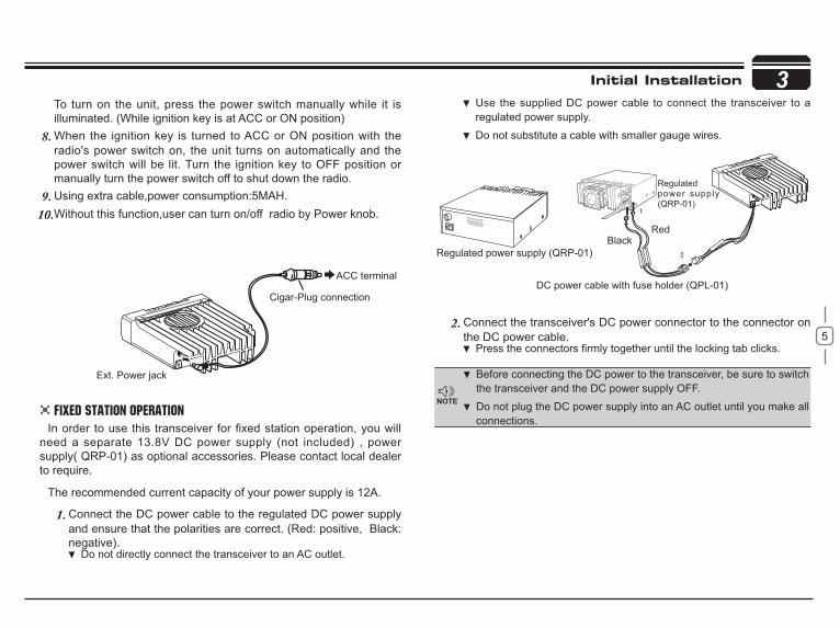
Before connecting the DC power to the transceiver, be sure to switch the transceiver and the DC power supply OFF.
Do not plug the DC power supply into an AC outlet until you make all connections.
need a separate 13.8V DC power supply (not included) , power supply( QRP-01) as optional accessories. Please contact local dealer to require.
The recommended current capacity of your power supply is 12A.
Connect the DC power cable to the regulated DC power supply 1.and ensure that the polarities are correct. (Red: positive, Black:negative).
Do not directly connect the transceiver to an AC outlet.
Use the supplied DC power cable to connect the transceiver to a regulated power supply.
Do not substitute a cable with smaller gauge wires.
To turn on the unit, press the power switch manually while it is illuminated. (While ignition key is at ACC or ON position)When the ignition key is turned to ACC or ON position with the 8.radio's power switch on, the unit turns on automatically and the power switch will be lit. Turn the ignition key to OFF position or manually turn the power switch off to shut down the radio.Using extra cable,power consumption:5MAH.9.Without this function,user can turn on/off radio by Power knob.10.
Connect the transceiver's DC power connector to the connector 2. onthe DC power cable.
.
Fixed Station Operation

6
3 Initial Installation
REPLACING FUSESIf the fuse blows, determine the cause, then correct the problem.
After the problem is resolved, replace the fuse. If newly installed fuses continue to blow, disconnect the power cable and contact your autho-rized dealer or an authorized servi-cecenter for assistance.
Only use fuses of the specified type and rating, otherwise the transceiver could be damaged.
After connecting the transceiver to the power supply, the supply voltage can be displayed on LCD by pressing the FUN key together with the
key.
The display immediately changes as the voltage supply changes, It also displays voltage during transmission.
The transceiver will return to its normal operation when the power is switched ON or repeat above operation.
of your installation will depend largely on the type of antenna and its correct installation. The transceiver can give excellent results if the antenna system and its installation are given careful attention.
impedance. Coupling the antenna to the transceiver via feed-lines having
system and can cause interference to nearby broadcast television receivers, radio receivers, and other electronic equipment.
Fuse Location Fuse Current RatingTransceiver 15A
Supplied Accessory DC power cable 20A
If you use the transceiver for a long period when the vehicle battery is not fully charged, or when the engine is OFF, the battery may become
using the transceiver in these conditions.
The range of displayed voltage is only from 7V to16V DC, because the displayed value is estimated, please use a voltmeter when a more precise reading is desired.
Power supply voltage Display
Antenna Connection
Transmitting without first connecting an antenna or other matched load may damage the transceiver. Always connect the antenna to the transceiver before transmitting.
The possible locations of antenna on a car are shown as following:
7
3
SP-01
SP-01 Ground
Microphone connector
Microphone [QHM-03]Antenna [QCA-01]
External speaker [SP-01]
Error
Initial Installation
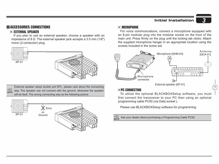
External Speaker Microphone
PC Connecting
If you plan to use an external speaker, choose a speaker with an
mono (2-conductor) plug.
For voice communications, connect a microphone equipped with an 8-pin modular plug into the modular socket on the front of the
the supplied microphone hanger in an appropriate location using the screws included in the screw set.
To utilize the optional BLACKBOXSetup software, you must first connect the transceiver to your PC then using an optional programming cable PC50 (via Data socket ).
Please use BLACKBOXSetup software for programming.
External speaker adopt double port BTL, please care about the connecting way. The speaker can not connect with the ground, otherwise the speaker will be fault. The wrong connecting way as the following picture.
Ask your dealer about purchasing a Programming Cable PC50.
Accessories Connections

8
4
NO. KEYPow(Power) Power on/OffVOL Adjust Volume Key
Main Dial Change frequency, memory channel and scan direction etc.
FUN/SET Function Key
V/M/MW Switches between VFO mode and Channelmode
MHz/SHIFT Step Size Key ( step:1MHz)TS/DCS/LOCK Sets CTCSS and DCS valueCAL/H/L Call keySQL/D Squelch off
Data Terminal Data reading/writing, cloning and theft alarm functions
TX lights during TransmittingMic.connector Microphone connection port
NO. KEYFUN/SETV/M/MW Stores data into channelsMHz/SHIFT Sets offset direction and offset frequencyTS/DCS/LOCK Sets Keypad lock function
CAL/ H/L Switches between HI, MID and LOW power transmission
SQL/D Compander mode on/off
NO. KEYPWR Reset to factory default settings V/M/MW Erase the memoryMHz/SHIFT Switches between Wide/ Narrow band TS/DCS/LOCK Auto dialerCAL/H/L Enters clone data function modeSQL/D Enters power supply voltage indication mode
NO. KEY
FUN/SET Press and hold for 2s to enter the Setting mode
SQL/D Monitor mode
Getting Acquainted
Front panel Press key until key.
Press
to be activated

9
4
21
NO. KEY
Ext. Power Jack
Terminal for connecting optional cable QCC01 for use with ignition key On/Off function.The radio will auto power on when car is driving. The radio will auto power off when car stops.
Ext.Speaker Terminal Terminal for optional external speaker SP01
Antenna Connector
NO. KEYSQL Squelch level.M In channel mode.
Indicates the channel number in channel mode.Decimal point Channel skip.
Decimal point Indicates the decimal point of frequency and the scanning function.Indicates the frequency or memory name.
Signal is being received or monitor.
Signal strength of receiving and transmitting.
Compander.Keypad lock .
DCS Set DCS function.Set CTCSS function.
+ _ Offset frequency direction.Scramble.
A Auto power off. Nar Narrow band. LO Low power.Mi Middle Power.
Pressing key.
3
Getting Acquainted
DISPLAY
Rear panel
3
1
2
13 10111214
4 5 6 7
8
91516171819 13

10
4
NO. KEY
UP Increase frequency ,channel number or setting value.
DOWN Decrease frequency, channel number or setting value.
PTT Press the PTT (Push-TO-Talk) key to transmit.
Number Key Input VFO frequency or DTMF dial out etc..
D T M F O N /OFF Switches between DTMF dialing or function operating.
LOCK Switch Locks out the UP Down Numerical keys and Function keys.
MIC Speak here during transmission.
microphone MIC Connector Diagram(in the front view of connector)
Getting Acquainted
11
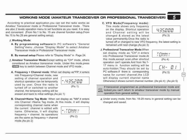
5According to practical application,you can set the radio works as
Amateur Transceiver mode or Professional Transceiver mode . There are also 2 levels operation menu to set functions as you need. It is easy and convenient (From No.1 to No. 15 are channel function setup,From No.15 to No.29 are general setting setup).
1.In PC software's "General
Setting"menu ,choose "Display Mode" to select Amateur Transceiver mode or Professional Transceiver mode.
:Please refer to "Display Mode" in Page 24.
2. Except setting as "CH" mode, others considered as Amateur transceiver mode. Under this mode,press
key to switch between Channel mode and VFO mode .
Professional Transceiver Mode3. When set display mode as "CH",it enters into Professional Transceiver mode.At this mode,except scan,other shortcut operation can't operate.And from No.1-17 menu in function setting will be auto-hidden,They should be set by PC software.If there is corresponding name for current channel,the LCD will display current channel name Otherwise,it shows current channel number. (As pic 4) (As pic 5)
Under every mode, from No. 18-29 menu in 4. general setting can be changed and saved.
C. :This mode shows only frequency on the display. Shortcut operation a n d C h a n n e l s e t t i n g w i l l b e changed & stored as the latest value permanently.Once the radio is turned off or changed to new VFO frequency, the latest setting is remained until next change.(As pic 3)
If transceiver programmed as professional transceiver mode and locked,you can't return to amateur transceiver mode by manual operation from general setting.
(Pic 1)
(Pic 2)
(Pic 4)
(Pic 5)A. : When set display as"FR",it enters into Frequency+Channel mode, new setting of channel operation and shortcut operation can be temporarily used by user. Once the radio is turned off or switched to another channel, the temporary setting will be erased and back to initial settings.(As pic 1)
B. : When set display as "NM",it enters into Channel +Name Tag mode. At this mode, it will display corresponding channel name when the current channel is edited with name. Otherwise, it wil l display frequency + channel. Its operations are the same as frequency + channel mode.(As pic 2)
(Pic 3)
WORKING MODE (AMATEUR TRANSCEIVER OR PROFESSIONAL TRANSCEIVER)

12
In standby, press key or Microphone's key until appear , this indicates current
channel in channel mode. Repeat above
6PWR KEY
Dial
Frequencydecrease
Frequencyincrease
Volume Knob
MinVolume
MaxVolume
Basic OperationsSwitching The Power On/Off
Adjusting The Volume
Switch between VFO and Channel mode
Adjusting Frequency/Channel THROUGH SELECTOR KNOB
Receiving
according to the option selected during installation Press the switch or turn the ignition key to ACC (speed up) or ON (startup) position to power on radio . Press the key for 1s or turn the ignition key to OFF position to turn off.
When the channel you are operating is called, the screen shows and field intensity, in this way, you can hear the calling from transmitting party.
Under frequency (VFO) mode, you can 1.change the current frequency to the desired one through selector knob; Turn clockwise to increase frequency; turn counterclockwise to decrease. Every gear will increase or decrease one step. Press key, the decimal point of
Turn the VOL knob clockwise to increase the audio level, counterclockwise to decrease.
During communication, volume can be adjusted more accurate.
5k, 6.25k, 8.33K,10k, 12.5k, 20k, 25k, 30k and 50k total nine step size available for this radio.
If the transceiver has set at higher squelch level, it may fail to hear the calling.
operation to switch between Frequency mode (VFO) and Channel mode.
frequency in screen will be auto-hidden. In this status, turn selector knob or Microphone [ / ] key will increase or decrease frequency quickly by 1MHz step .Under channel mode, you can change the current channel to the 2.desired one through selector knob, clockwise turn to the forward channel, anticlockwise turn to the backward channel. In relative working mode, Microphone's [ / ] key has same function for adjusting frequency and channel.
TransmittingPress and hold key or press MIC's key to monitor for a while
Release or press Mic's key to return standby status,Then press and hold [PTT] key to speak
into microphone.
When the channel you are operating is called,the screen shows BUSY and field intensity,you can't hear the calling from transmitting party,it means current channel receives a matching carrier but unmatching signaling(Refer to CTCSS/DCS encode and decode or Optional Signaling setup).
13
Basic Operations
Transmitting Tone-Pulse
Transmitting OPTIONAL SIGNALING
Press and hold [PTT] key, then press Microphone [ ] key to
transmit current selected tone-pulse signal.
Press and hold [PTT] key, then press Microphone key or press key in front panel or press Mic's key to transmit pre-stored and
selected DTMF/2Tone/5Tone optional signaling.
Channel Edit
Channel Delete
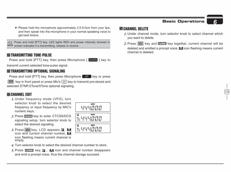
Under frequency mode (VFO), turn 1.selector knob to select the desired frequency or input frequency by MIC's numeric keys.Press2. key to enter CTCSS/DCS signaling setup, turn selector knob to select the desired signaling.
Press3. key, LCD appears , icon and current channel number,
Under channel mode, turn selector knob to select channel which 1.you want to delete.
Press2. key and key together, current channel will be deleted and emitted a prompt voice. channel is deleted.
empty.Turn selector knob to select the desired channel number to store.4.Press 5. key, , icon and channel number disappears and emit a prompt voice, thus the channel storage succeed.
6
Press and hold [PTT] key, LED lights RED and power intensity showed in screen indicates it is transmitting, release to receive.
Please hold the microphone approximately 2.5-5.0cm from your lips,and then speak into the microphone in your normal speaking voice to get best timbre.
14
7 Shortcut Operations
Squelch level Setup
Frequency/Channel Scan
Channel Scan
CTCSS/DCS Encode and Decode setup
Setting the radio to a tight squelch level,you can avoid unwanted signals or noise,but you may not receive a weak signal. Therefore,it will be better for you to select the normal squelch level.
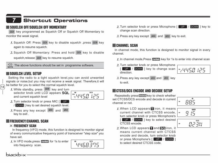
In frequency (VFO) mode, this function is designed to monitor signal of every communicative frequency point of transceiver "step size" you have set.
In channel mode, this function is designed to monitor signal in every channel.
In channel mode,Press 1. key for 1s to enter into channel scan
Repeatedly press key to check whether set CTCSS/DCS encode and decode in current channel or not.
When LCD appears1. iron, it means current channel with CTCSS encode, turn selector knob or press Microphone's [ / ] key to select desired CTCSS encode.When LCD appears2. and iron, it means current channel with CTCSS encode and decode, turn selector knob or press Microphone's [ / ] to select desired CTCSS code.
While standby, press 1. key and turn selector knob until LCD appears and current squelch levelTurn selector knob or press MIC [ 2./ ] key to set desired squelch level.
Press any key except 3. and key to exit .
Frequency Scan
In VFO mode,press 1. for 1s to enter into frequency scan.
Turn selector knob or press Microphone [ 2. / ] key to change scan direction.
Press any key except 3. and key to exit.
Turn selector knob or press Microphone 2.[ / ] key to change scan direction.
Press any key except3. and key to exit.
squelch off/squelch off momeNTARY key programmed as Squelch Off or Squelch Off Momentary to
monitor the weak signal.
Squelch Off: Press1. key to disable squelch ,press key again to resume squelch.
Squelch Off Momentary: Press and hold2. key to disable
squelch,release key to resume squelch.
The above functions should be set in programme software.

15
7Shortcut Operations
CTCSS SCANRepeatedly press key until LCD
displays and icons ,then hold key for 1S to enter into CTCSS scanning.
will stop for 15s then scan again.
Under channel mode,this operation can be temporarily used by user. Once the radio is turned off or switched to another channel,the temporary setting will be erased.
When LCD appears 3. iron, it means current channe can be set with DCS encode and decode together, turn selector knob or press Microphone's [ / ] to select desired DCS encode and decode.CTCSS:62.5-254.1, Total 51groups; DCS:000N-777I total 1024 4.groups. N is positive code, is inverse code.
Press any key except 5. , and keys to return into standby status.
Repeatedly press key until LCD displays DCS icons ,then hold key for
a matching DCS signaling ,it will stop for 15s then scan again.
compander function.
Press key until LCD display iron,
then press key to switch between high/Mid/low power. The LCD appears:
None: Transmit in high power
: Transmit in middle power
: Transmit in low power
Compander function will decrease the background noise and enhanceaudio clarity, especially in long range communication.
Press1. key, then press key to turn on compander function, repeat above operation again to turn off
HIGH/MID/LOW Power switch
Compander (Decrease the background noise and ENHANCE AUDIO CLARITY)
When LCD appears 2. iron, enable compander in current channel.When LCD doesn't display 3. iron, disable compander in current channel.
DCS SCAN

16
Press key until LCD displays1.icon, then press key until, LCD displays icon, it indicates keypad lockout function is valid.
This will automatically transmit pre-programmed and stored DTMF tones. And they are often used to remote control electronic devices or AUTOPATCH phone systems available on some repeater.
Press and hold 1. key, then press key to enter the auto-dialer enquiry mode, LCD displays current default data and current group displayed on left. If no data in current group,it shows"EMPTY".
Press and hold key, then press 1.key, LCD displays current battery voltage.Repeat above operation to return into 2.VFO or Channel mode
frequency.When LCD displays " " icon, it indicates negative offset, which 4.means transmitting frequency lower than receiving frequency.Turn selector knob or Mic's [ 5. / ] key to change offset frequency, offset frequency changed as per stepping.
Press any key except 6. and key to exit into standby.
Press 1. key until the icon displays on the LCD, then press key, LCD displays offset direction and offset frequency.Repeatedly press key to select 2.positive offset and negative offset.When LCD displays " " icon, it indicates 3.positive offset, which means transmitting f r e q u e n c y h i g h e r t h a n r e c e i v i n g
7Repeater receives a signal(UP-LINK) on one frequency and re-
transmits on another frequency(DOWN-LINK). The difference between these two frequencies is called the offset frequency. If the UP-LINK frequency higher than DOWN-LINK frequency, the direction is positive, If it is lower, the shift direction is negative.
Avoiding unintentional operation, this function will lock main keys, all keys except and key are invalid.
Offset Direction and offset frequency setup KEYPAD LOCKOUT
Current Voltage ENQUIRY
Auto-Dialer Setup
Shortcut Operations
In voltage display mode, all functions and channel or frequency selection are invalid.
This function will display Current Battery Voltage.
Repeat above operation, 2. icon disappears, it indicates keypad lockout function is invalid.
Under channel mode,this operation can be temporarily used by user. Once the radio is turned off or switched to another channel,the temporary setting will be erased.

17
Turn selector knob to choose group you 2.desired. Total:16 group,01-16.
7Shortcut Operations
Press3. key to enter into editing of current group,press MIC's numeric keys to set your desired data.The display scrolls when the 7th digit 4.is entered. The numbers 0-9, --, A-D, *and # can be stored up to a total of 23 digits.
After editing,press PTT or5. key to send current group and store edited DTMF signaling. Press to exit and store.
Press1. key, then press key to enter into auto-dialer enquiryTurn selector knob to select desired 2.transmitting groupPress PTT or3. key to transmit current selected DTMF tones.
Transmitting Edited DTMF tones in the Auto-dialer memory

18
Press2. / key to choose No.01 menu, LCD displays ”STP--125”Turn selector knob to select the desired frequency channel step.3.Channel step: 5K,6.25K,8.33K,10K,12.5K,20K,25K,30K and 50K, total 9 kinds.Press4.
Press and hold 1. key for over 2s to enter general setting menu.
Press and hold1. key for over 2s to enter general setting menu.
Press2. or to select the desired function option.Turn selector knob to select the desired setup.3.Press4.
Meanwhile,if you want to edit channel name or start up menu,pressor to move forward or backward,Press to store and
exit.
Only in frequency (VFO) mode, this function is valid. Turn selector knob to select frequency or frequency scanning which is restricted by frequency step size.
8 General Setting
Frequency Channel Step Setup
This function is auto-hidden in channel mode.
DTMF, DTMF ANI, 2Tone or 5Tone SignalingDTMF/5Tone/2Tone signalling function as similarily as CTCSS/DCS.
Without receiving correspondent tone signalling, the speaker will remain mute. DTMF and 5Tone signalling can be applied for other advanced
features such as ANI, PTT ID, group call, remotely stun,remotely kill,waken,...etc. The signalling edition must be done through programming software. Please refer to the HELP option in the programming software to know how to operate these features.
Press and hold 1. key for over 2s to enter into general setting menu.
Press 2. / to choose No 2 menu,LCD displays"T-OFF" .
Turn selector knob to 3. select the desired setup."DTMF”: the channel will be mute by a DTMF signal. The speaker won’t be open until receiving a correspondent DTMF signal. Hold "PTT" then press or press directly to transmit the pre-stored DTMF signaling.
In Profession transceiver mode,the functions from No.1 to No.17 will be auto-hidden.
In DTMF signaling mode,press for 2s until LCD displays "AN---",turn selector knob to select desired digit(the other party ID).In this mode,press to confirm exist digit and move cursor to next,press to forward cursor.After editing,press
key to operate ANI call.
"2TONE": the channel will be mute by a 2-Tone signal. The speaker won’t be open unti l receiving a correspondent 2-Tone signal.Hold “PTT” then press or press
directly to transmit the pre-stored 2-Tone signaling.
"5Tone": the channel will be mute by a 5-Tone signal. The Speaker won’t be open until receiving a correspondent 5-Tone signal. hold “PTT” then press or Press directly to

19
8
Sending 5-Tone Call
Press2. / key t o choose No.04 menu, LCD displays "5TON XX","XX"indicates the group in the list.Turn selector knob to select the desired 3.sending 5TONE group,Press PTT to transmit selected group. Total:100groups,00-99,Default:00.4.Press5.
General Setting
Content and name of 5TONE will be edited by programming software.This radio only query edited group or name.If there is corresponding name for 5TONE,this operation will display 5TONE corresponding name.
transmit the pre-stored 5-Tone signaling.
In 5Tone signaling mode,press for 2s until LCD displays "AN---",turn selector knob to select desired digit(caller ID).In this mode,press next,press to forward cursor.After editing,press key to operate ANI call.
Press4.
Sending 2-Tone CallPress and hold 1. key for over 2s to enter general setting menu.
P ress2. / key t o choose No.03 menu, LCD displays "2TON XX","XX"indicates the group in the list.Turn selector knob to select the desired 3.sending 2TONE group,Press PTT to transmit selected group. Total:32groups,00-31,Default:00.4.Press5.Content and name of 2TONE will be edited by programming software.This radio only query edi ted group or name.I f there is corresponding name for 2TONE,this operation will display 2TONE corresponding name.
Press and hold1. key for over 2s to enter general setting menu
Sending DTMF callPress and hold 1. key for over 2s to enter general setting menu.
P ress2. / key t o choose No.05 menu, LCD displays "DTMF XX","XX"indicates the group in the list.Turn selector knob to select the desired 3.sending DTMF group,Press PTT to transmit selected group. Total:16groups,00-16,Default:00.4.Press5.
Signaling Combination setupThis function is to improve the level of protecting the radio against
receiving irrelative signal.
20
8
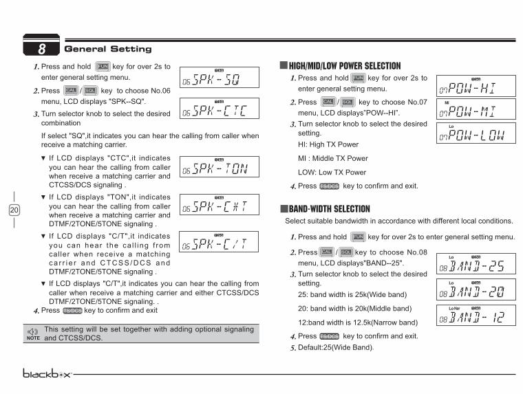
Turn selector knob to select the desired 3.combination
If select "SQ",it indicates you can hear the calling from caller when receive a matching carrier.
If LCD displays "CTC",it indicates you can hear the calling from caller when receive a matching carrier and CTCSS/DCS signaling .
If LCD displays "TON",it indicates you can hear the calling from caller when receive a matching carrier and DTMF/2TONE/5TONE signaling .
If LCD displays "C/T",it indicates you can hear the ca l l ing f rom caller when receive a matching c a r r i e r a n d C T C S S / D C S a n d DTMF/2TONE/5TONE signaling .If LCD displays "C/T",it indicates you can hear the calling from caller when receive a matching carrier and either CTCSS/DCS DTMF/2TONE/5TONE signaling. .
Press4.
HIGH/MID/LOW Power SelectionPress and hold1. key for over 2s to enter general setting menu.
Press2. / key to choose No.07 menu, LCD displays”POW--HI”.Turn selector knob to select the desired 3.setting.HI: High TX Power
MI : Middle TX Power
LOW: Low TX Power
Press4.
Band-width SelectionSelect suitable bandwidth in accordance with different local conditions.
Press and hold 1. key for over 2s to enter general setting menu.
Press2. / key to choose No.08 menu, LCD displays"BAND--25".Turn selector knob to select the desired 3.setting.25: band width is 25k(Wide band)
20: band width is 20k(Middle band)
12:band width is 12.5k(Narrow band)
Press4.Default:25(Wide Band)5. .
General Setting
Press and hold 1. key for over 2s to enter general setting menu.
Press2. / key to choose No.06 menu, LCD displays "SPK--SQ".
This setting will be set together with adding optional signaling and CTCSS/DCS.

21
8TX OFF SETUP
Disable this function,it is invalid to press PTT,current channel only works in RX mode.
Press and hold 1. key for over 2s to enter general setting menu.
Press2. / key to choose No.09 menu, LCD displays"TX-ON".Turn selector knob to select the desired 3.setting .On:In current channel,Press PTT to transmit
OFF:In current channel,Press PTT is invalid.
Press4.
Busy Channel LockoutBCLO is to disable transmitting while RX signal is received. Once the
channel is busy and you press PTT, the radio will beep as warning and get back to receiving.
Press and hold 1. key for over 2s to enter general setting menu
Press2. / key to choose No.10 menu, LCD displays"LOCK--OFF".Turn selector knob to select the desired 3.setting.
BU: Enable BCLO, Carrier lockout, transmitting is inhibited when current channel receives a matching carrier;press [PTT] to emit error voice prompt and back to receiving status.
RL: Enable BTLO, transmitting is inhibited when current channel receives a matching carrier but dis-matching CTCSS/DCS.press [PTT] to emit error voice prompt and back to receiving status.
OFF: Busy channel lockout is disabled.It can transmit in any receiving status.
Press4.
Press and hold 1. key for over 2s to enter general setting menu.
Press 2. / key to choose No.11
Turn selector knob to select the desired letter,press 3. key to to
return forward edition.After edition,press 4. key to exit.
Reverse TX/RX
General Setting
Editing Channel NAME
In Frequency (VFO) mode ,this function will be auto-hidden.
TX frequency turns to RX frequency & RX frequency changes to TX frequency. The signaling will also be reversed if CTCSS/DCS signaling exited in this channel.
Press and hold 1. key for over 2s to enter general setting menu
22
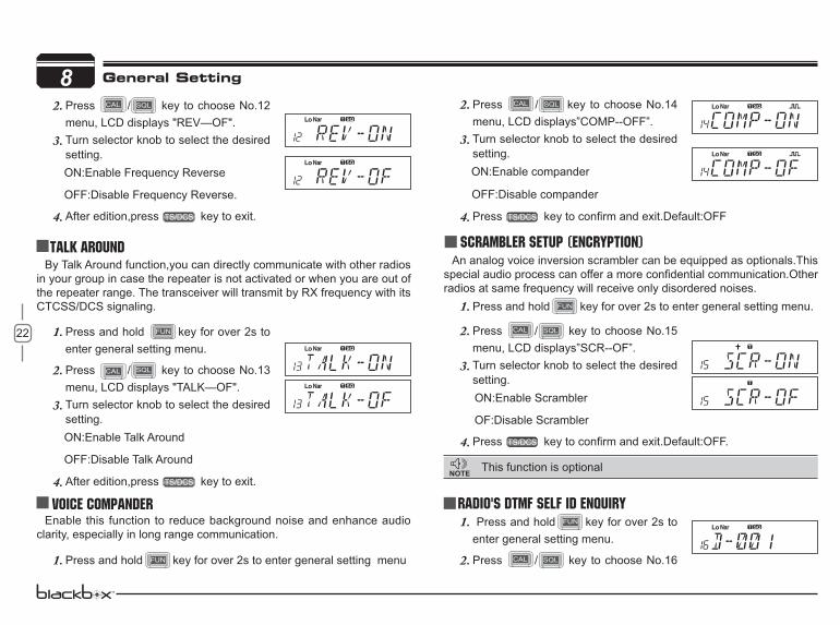
8Press2. / key to choose No.12 menu, LCD displays "REV—OF".Turn selector knob to select the desired 3.setting.
ON:Enable Frequency Reverse
OFF:Disable Frequency Reverse.
After edition,press 4. key to exit.
Talk Around
Press 2. / key to choose No.14 menu, LCD displays”COMP--OFF”.Turn selector knob to select the desired 3.setting.
ON:Enable compander
OFF:Disable compander
Press4.Scrambler setup (Encryption)
An analog voice inversion scrambler can be equipped as optionals.This
radios at same frequency will receive only disordered noises.
General Setting
By Talk Around function,you can directly communicate with other radios in your group in case the repeater is not activated or when you are out of the repeater range. The transceiver will transmit by RX frequency with its CTCSS/DCS signaling.
Press and hold 1. key for over 2s to enter general setting menu.
Press2. / key to choose No.13 menu, LCD displays "TALK—OF".Turn selector knob to select the desired 3.setting.
ON:Enable Talk Around
OFF:Disable Talk Around
After edition,press 4. key to exit.
Voice Compander Enable this function to reduce background noise and enhance audio
clarity, especially in long range communication.
Press and hold1. key for over 2s to enter general setting menu
Radio's DTMF SELF ID ENQUIRY
This function is optional
Press and hold1. key for over 2s to enter general setting menu.
Press2. / key to choose No.16
Press and hold1. key for over 2s to enter general setting menu.
Press2. / key to choose No.15 menu, LCD displays”SCR--OF”.Turn selector knob to select the desired 3.setting.
ON:Enable Scrambler
OF:Disable Scrambler
Press4.

23
8menu, LCD displays”D--XXX” XXX is radio's DTMF SELF ID. Press3.
Radio's 5TONE SELF ID ENQUIRYPress and hold1. key for over 2s to enter general setting menu.
Press2. / key to choose No.17 menu, LCD displays"F--XXXXX", "XXXXX" is radio's 5TONE SELF ID. Press3.
Voice PromptThe prompting tone provides confirmation of entry, error status or
malfunctions of the transceiver. You can enable or disable this function.
Press and hold1. key for over 2s to enter general setting menu.
Press2. / key to choose No.18 menu, LCD displays"BEEP--ON".Turn selector knob to select the desired 3.setting.
ON:Enable voice prompt
OFF:Disable voice prompt
Press4.
TOT (Time-out timer)The time-out timer limits the amount of transmitting time. When you
reach the time limit which has been programmed by your dealer, your transmission will be cut off. In order to transmit again, you must release PTT button to reset the timer.
Press and hold1. key for over 2s to enter general setting menu.
Press2. / key to choose No.19 menu, LCD displays"TOT--3"Turn selector knob to select the desired 3.setting.
Timer:1-30min,each level 1min
OFF:Disable TOT
Press4.
APO (Auto power off)Once APO is activated, the radio will be automatically switched off
when the pre-set timer is running to end.
Press and hold1. key for over 2s to enter general setting menu.
Press2. / key to choose No.20 menu, LCD displays"APO--OFF".Turn selector knob to select the desired 3.setting.
30MIN:Auto power off after 30m
General Setting
Suggestion:Enable this function to check incorrect operation and malfunctions.
24
8 1HOUR:Auto power off after 1h
2HOUR:Auto power off after 2h
OFF:Disable Auto power off
Press4.
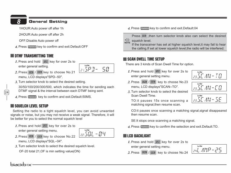
DTMF Transmitting TimePress and hold 1. key for over 2s to enter general setting.
Press2. / key to choose No.21 menu, LCD displays"SPD--50".Turn selector knob to select the desired setting. 3.30/50/100/200/300/500, which indicates the time for sending each DTMF signal & the interval between each DTMF being sent.
Press4.
Squelch level SetupSetting the radio to a tight squelch level, you can avoid unwanted
signals or noise, but you may not receive a weak signal. Therefore, it will be better for you to select the normal squelch level
Press and hold1. key for over 2s to enter general setting menu.
Press2. / key to choose No.22 menu, LCD displays"SQL--04".Turn selector knob to select the desired squelch level.3.
OF-20 total 21,OF is min setting value(ON)
Press4.
Scan Dwell Time SetupThere are 3 kinds of Scan Dwell Time for option.
Press and hold1. key for over 2s to enter general setting menu.
Press2. / key to choose No.23 menu, LCD displays"SCAN--TO".Turn selector knob to select the desired 3.Scan Dwell Time.TO:it pauses 15s once scanning a matching signal,then resume scan.
CO:it pauses once scanning a matching signal,signal disappeared then resume scan.
SE:It stops once scanning a matching signal.
Press4.
LCD BacklightPress and hold1. key for over 2s to enter general setting menu.
Press2. / key to choose No.24
General Setting
Press ,then turn selector knob also can select the desired squelch level.If the transceiver has set at higher squelch level,it may fail to hear the calling.If set at lower squelch level,the radio will be interfered.
25
8menu, LCD displays"LAMP--25"Turn selector knob to select the desired LCD backlight brightness 3.1-32 total 32 level backlight brightness.Press4.
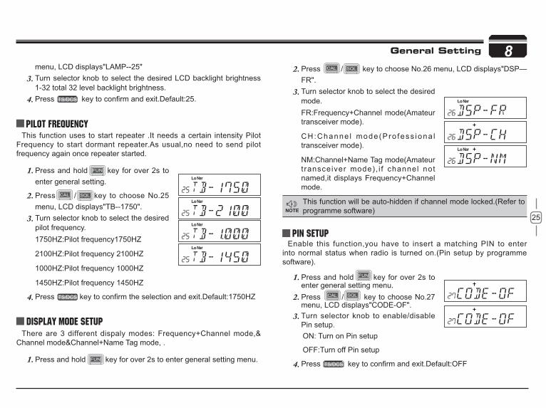
Pilot FrequencyThis function uses to start repeater .It needs a certain intensity Pilot
Frequency to start dormant repeater.As usual,no need to send pilot frequency again once repeater started.
Press and hold1. key for over 2s to enter general setting.
Press2. / key to choose No.25 menu, LCD displays"TB--1750".Turn selector knob to select the desired 3.pilot frequency.1750HZ:Pilot frequency1750HZ
2100HZ:Pilot frequency 2100HZ
1000HZ:Pilot frequency 1000HZ
1450HZ:Pilot frequency 1450HZ
Press4.
Display Mode SetupThere are 3 different dispaly modes: Frequency+Channel mode,&
Channel mode&Channel+Name Tag mode, .
Press and hold1. key for over 2s to enter general setting menu.
Press2. / key to choose No.26 menu, LCD displays"DSP—FR".Turn selector knob to select the desired 3.mode.FR:Frequency+Channel mode(Amateur transceiver mode).
CH:Channe l mode(Pro fess iona l transceiver mode).
NM:Channel+Name Tag mode(Amateur t ransceiver mode), i f channel not named,it displays Frequency+Channel mode.
Press4.
PIN Setup Enable this function,you have to insert a matching PIN to enter
into normal status when radio is turned on.(Pin setup by programme software).
Press and hold1. key for over 2s to enter general setting menu.Press2. / key to choose No.27 menu, LCD displays"CODE-OF".Turn selector knob to enable/disable 3.Pin setup.
ON: Turn on Pin setup
OFF:Turn off Pin setup
Press4.
This function will be auto-hidden if channel mode locked.(Refer to programme software)
General Setting

26
8Address list
You store desired ID and corresponding ID name in address list.The LCD displays ID corresponding name if radio received ANI calling and
Factory DefaultIf your radio seems to be malfunctioning, resetting the microprocessor
may solve the problem. When performing the reset, you may lose memory data and stored information. Back up or write down important data before performing the reset.
General Setting
Press and hold1. key for over 2s to enter general setting menu.
Press2. / key to choose No.29 menu, LCD displays"RESTORE".Turn selector knob to select the desired 3.operation.FACT:Resume factory defaul t for channel,signaling and general setting.
SETUP:Return initial setup for No.18-No 27 general setting menu.
Press4.
Press and hold1. key for over 2s to enter general setting menu.
Press2. / key to choose No.28 menu, LCD displays"BOOK".
P r e s s3. t o e n t e r i n t o I D setting,press / to select the desired group (00-127,total is 128 group ID).Turn selector knob to select desired number,presscursor to next edition,press to clear out all digits.After finishing edition,press 4. to confirm and enter into edition of current group's ID corresponding name.Turn selector knob to select desired letter,press to move cursor to next edition,Press to clear out all letters. 00-127,total 128 groupID and corresponding ID name.Press5.Step 3 and Step 4 operations to edit multi-ID and corresponding ID name.Press6. key to return into standby status.

27
9
You can operate the transceiver by keypad or input desired frequency or channel through the QHM-03 microphone (Note:In professional transceiver mode,other keys are invalid except PTT,[ / ],
and ).
Keypad LockPull down the slide switch to lock position,The lamp is turned off and
all of keypads is not work except PTT switch.
Transmitting DTMF By Microphone KeyPAD
Switches between VFO and channel mode In standby,press key to switch between channel mode and
Frequency mode (VFO).
Short CallingIn standby,press to transmit the selected DTMF/2TONE/5TONE in current channel.
:In standby,press ,LCD displays DTMF data and group.Press [ / ] key to select the desired transmitting DTMF group,then Press PTT to transmit.
If no DTMF data in current group,LCD displays "EMPTY",press key again and input desired DTMF code by keypad,press PTT to transmit and store DTMF data.
Squelch LevelIn standby,press 1. ,then press ,LCD displays "SQL" and current squelch level.Press2. / to adjust the desired squelch level.(press
,then press ,turn selector knob also can adjust the desired squelch level.
3. Optional signalingIn standby,press ,then press to add
optional signaling,repeat above operation to set DTMF,2TONE or 5TONE signaling.
When f i r s t b i t o f Exa by te i n frequency displays "D",it indicates DTMF function enable.
When f i r s t b i t o f Exa by te i n frequency displays "T",it indicates 2Tone function enable.
Microphone Operation
Slide DTMF key to DTMF position, press and hold the [PTT] key, transmitting the desired DTMF signaling by the numeric key directly.(Note:Slide DTMF key to DTMF position,the keyboard is invalid in standby ).
Function Setup By Microphone Keypad:In standby, press key,
the squelch is disabled when icon , Press again to enable
squelch and the icon disappears.
PTT
DOWNUP
LockSpeaker
Numeric Keys
DTMF ON/OFF

28
9
Reverse TX/RXTX frequency turns to RX frequency & RX
frequency changes to TX frequency. The signaling will also be reversed if CTCSS/DCS signaling exited in this channel.
In standby,press 1. ,then press ,LCD displays “REV—OF”.Press [ 2. / ] to select the desired value.ON:Enable Frequency Reverse
OFF:Disable Frequency Reverse
3.
In corresponding mode,press then press key to enter into scanning.
In scanning mode,press / to change scan direction.
Busy Channel LockoutBCLO is to disable transmitting while RX signal is received. Once the
channel is busy and you press PTT, the radio will beep as warning and get back to receiving.
In standby,press 1. ,then press to enter into Busy Channel Lockout.Press [ 2. / ] to select the desired value.
BU: Enable BCLO, Carrier lockout, transmitting is inhibited when current channel receives a matching carrier;press [PTT] to emit error voice prompt.RL: Enable BTLO, transmitting is inhibited when current channelreceives a matching carrier but dis-matching CTCSS/DCS.press [PTT] to emit error voice prompt It can transmit in any receiving status.OFF: Busy channel lockout is disabled.3.
This function can be temporarily used in channel mode. Once the radio is turned off or switched to another channel, the temporary setting will be erased and back to initial settings.
Frequency/Channel scan
Scan Skip
When first bit of Exa byte in frequency displays "F",it indicates 5Tone function enable.
This function can be temporarily used in Channel mode . Once the radio is turned off or switched to another channel, the temporary setting will be erased and back to initial settings.
This function can be temporarily used in Channel mode . Once the radio is turned off or switched to another channel, the temporary setting will be erased and back to initial settings.
Microphone Operation
In Channel mode,press then press ,decimal point displayed between frequency's ten digit and unit digit,it means current channel is scan skip. Repeat above operation to set scan or scan skip in current channel.
decimal point displayed between frequency's ten digit and unit 1.digit,it means current channel is scanned skip.decimal point is not displayed between frequency's ten digit and 2.unit digit,it means current channel is scanned.
29
9TOT (Time-out timer)
The time-out timer limits the amount of transmitting time. When you reach the time limit which has been programmed by your dealer, your transmission will be cut off. In order to transmit again, you must release PTT button to reset the timer.
In standby,press 1. ,then press “LCD displays "TOT-X".
Press [ 2. / ] to select the desired value.3.
CTCSS/DCS Encode and DecodeIn standby,press 1. ,then press to enter into CTCSS/DCS Encode and Decode.Repeat above operation to set as below:2.
LCD displays T icon,it indicates CTCSS encode set in current channel.
LCD displays T and SQ icon,it indicates CTCSS encode and decode set in current channel.
LCD displays DCS icon,it indicates DCS encode and decode set in current channel.
In corresponding icon,press [ 3. / ] to select the desired CTCSS/DCS encode and decode.
Press4. `
Talk Around
This function can be temporarily used in Channel mode. Once the radio is turned off or switched to another channel, the temporary setting will be erased and back to initial settings.
By Talk Around function,you can directly communicate with other radios in your group in case the repeater is not activated or when you are out of the repeater range. The transceiver will transmit by RX frequency with its CTCSS/DCS signaling.
In standby,press 1. ,then press key,LCD displays “TALK--OF”.Press [ 2. / ] to select the desired setting .
ON:Enable Talk Around
OFF:Disable Talk Around
3.This function can be temporarily used in Channel mode . Once the radio is turned off or switched to another channel, the temporary setting will be erased and back to initial settings.
Voice PromptThe prompting tone provides confirmation of entry, error status or
malfunctions of the transceiver. You can enable or disable this function.
In standby,press 1. ,then press ,LCD displays "BEEP--XX”.Press [ 2. / ] to turn on/off BEEP voice prompt.
BEEP—OF :turn off voice prompt
BEEP—ON :turn on voice prompt
Press number key to exit and store.3.
HIGH/MID/LOW Power SelectionIn standby,press 1. ,then press ,LCD displays"POW-XX".Press [ 2. / ] to select the desired power.
Microphone Operation

30
9 HI:High Power
MI:Middle Power
LOW:Low Power
Press number keys to exit and store.3.
LCD Backlight In standby status,press 1. , then press LCD displays"LAMP-XX" .Press [ 2. / ] to select desired backlight brightness(1-32 levels).
3.
Microphone Operation

31
10
Connect DC power cable with car battery.Connect the optional alarm cable QL-01(A) to the data jack on 1.the front panel as shown. Secure the other end of the cable to an
not enough long, you can choose optional alarm cable QL-01 (B) to extend).When transceiver power off by press 2.
key ,the long-distance anti-theft alarm enable.Note:The long-distance anti-theft alarm only available when 3.transceiver power off .
When the alarm cable QL-01(A) or QL-01(B) is removed from the 4.DATA jack or cut by improper sequence, the alarm function enable and will alarm as programmed. In alarming,the transceiver will stop alarm once receiving a matching signal. And alarm again when a matching signal disappeared.Restart radio to cancel anti-theft alarming.Reconnect with alarm 5.cable and turn off radio,the system will return to alarm mode.
This function is mainly use for simple anti-theft alarm device in vehicles. When the transceiver be removed in an improper manner,the transceiver will emit and transmit alarming and background voice to system and other transceiver of the same frequency.
Steering-wheel etc.
Alarm cable [QL-01(B)]
DC power cabcle
Battery
Alarm cable [QL-01(A)]
Long-distance Anti-theft Alarm
32
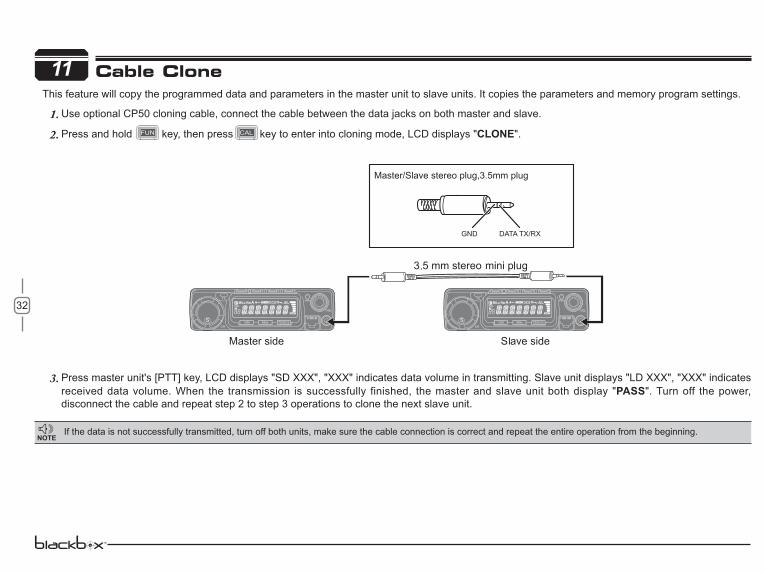
11This feature will copy the programmed data and parameters in the master unit to slave units. It copies the parameters and memory program settings.
Use optional CP50 cloning cable, connect the cable between the data jacks on both master and slave.1.Press and hold key, then press key to enter into cloning mode, LCD displays "2. CLONE".
Press master unit's [PTT] key, LCD displays "SD XXX", "XXX" indicates data volume in transmitting. Slave unit displays "LD XXX", "XXX" indicates 3.received data volume. When the transmission is successfully finished, the master and slave unit both display "PASS". Turn off the power, disconnect the cable and repeat step 2 to step 3 operations to clone the next slave unit.
Cable Clone
If the data is not successfully transmitted, turn off both units, make sure the cable connection is correct and repeat the entire operation from the beginning.
GND DATA TX/RX
Master/Slave stereo plug,3.5mm plug
33
12Programming Software Installing and Starting (in windows XP system)
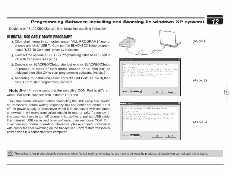
Double click ”BLACKBOXSetup“, then follow the installing instruction.
Install USB Cable Driver Programme(As pic 1)
(As pic 2)
(As pic 3)
Click start menu in computer, under “ALL PROGRAMS” menu, 1.choose and click “USB To Com port” in BLACKBOXSetup program, install “USB To Com port” driver by indication.
Connect the optional PC50 USB Programming cable to USB port in 2.PC with transceiver.(As pic 1)
Double click 3. BLACKBOXSetup shortcut or click BLACKBOXSetupin procedure index of start menu, choose serial com port as indicated then click OK to start programming software. (As pic 2)
According to instruction,select correct"COM Port"(As pic 3),then 4.click "OK" to start programming software.
Even in same computer,the selective COM Port is different when USB cable connects with different USB port.
You shall install software before connecting the USB cable line. Switch on transceiver before writing frequency.You had better not switch on or off the power supply of transceiver when it is connected with computer, otherwise, it will make transceiver unable to read or write frequency. In this case, you have to turn off programming software, pull out USB cable.then reinsert USB cable and open software, then rechoose COM Port, it will turn into normal operation. Therefore, please connect transceiver with computer after switching on the transceiver. Don't restart transceiver power when it is connected with computer.

34
13
DCS encode and decode
VFO frequency 145.00MHz DCS code 023N
Memory channel Output power HI
Offset direction Key-lock setting OFF
Offset frequency 600KHz TOT OFF
Channel step 12.5KHz APO OFF
CTCSS encode and decode Squelch Level 4
CTCSS frequency 88.5Hz
Default Setting after Resetting(VHF)
DCS encode and decode
VFO frequency 435.00MHz DCS code 023N
Memory channel Output power HIOffset direction Key-lock setting OFFOffset frequency 5MHz TOT OFF
Channel step 25KHz APO OFFCTCSS encode and decode Squelch Level 4
CTCSS tone frequency 88.5Hz
Default Setting after Resetting(UHF)
Trouble ShootingProblem Possible Causes and Potential Solutions
Power is on, nothing appears on Display.
+ and - polar i t ies of power connect ion are reversed. Connect red lead to plus terminal and black lead to minus terminal of DC power supply.
Fuse is blown. Check and solve problem resulting in blown fuse and replace fuse with new fuse.
Display is too dim. Dimmer setting is "LAMP-L". Please make the dimmer setting "LAMP-H".
No sound comes from speaker. CTCSS/DCS squelch is active. Turn
CTCSS or DCS squelch off.
Key and Dial do not function.
Key-lock function is activated. Cancel Key-lock function.
Rotating Dial will not change memory channel.
Transceiver is in CALL mode. Press the VFO or memory mode.
PTT key is pressed but transmission does not occur.
microphone properly.
properly.
Maintenance
35
14
technology.
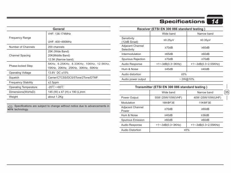
General
Frequency RangeVHF: 136-174MHz UHF: 400~490MHz
Number of Channels 200 channels
Channel Spacing25K (Wide Band)20K(Middle Band)12.5K (Narrow band)
Phase-locked Step5KHz, 6.25KHz, 8.33KHz, 10KHz, 12.5KHz, 15KHz, 20KHz, 25KHz, 30KHz, 50KHz
Operating Voltage 13.8V DC ±15%
Squelch Carrier/CTCSS/DCS/5Tone/2Tone/DTMF
Frequency Stability ±2.5ppm
Operating Temperature -20 ~+60
Dimensions(WxHxD) 145 (W) x 47 (H) x 190 (L)mm
Weight about 1.2Kg
Wide band Narrow bandSensitivity(12dB Sinad)Adjacent ChannelSelectivityIntermodulation
Spurious Rejection
Audio Response +1~-3dB(0.3~3KHz) +1~-3dB(0.3~2.55KHz)
Hum & Noise
Audio distortion
Audio power output 2W@10%
Wide band Narrow band
Power Output 55W /25W/10W(VHF) 40W /25W/10W(UHF)
ModulationAdjacent Channel PowerHum & Noise
Spurious Emission
Audio Response +1~-3dB(0.3~3KHz) +1~-3dB(0.3~2.55KHz)
Audio Distortion
Specifications

36
15
67.0 79.7 94.8 110.9 131.8 156.7 171.3 186.2 203.5 229.1
69.3 82.5 97.4 114.8 136.5 159.8 173.8 189.9 206.5 233.6
71.9 85.4 100.0 118.8 141.3 162.2 177.3 192.8 210.7 241.8
74.4 88.5 103.5 123.0 146.2 165.5 179.9 196.6 218.1 250.3
77.0 91.5 107.2 127.3 151.4 167.9 183.5 199.5 225.7 254.1
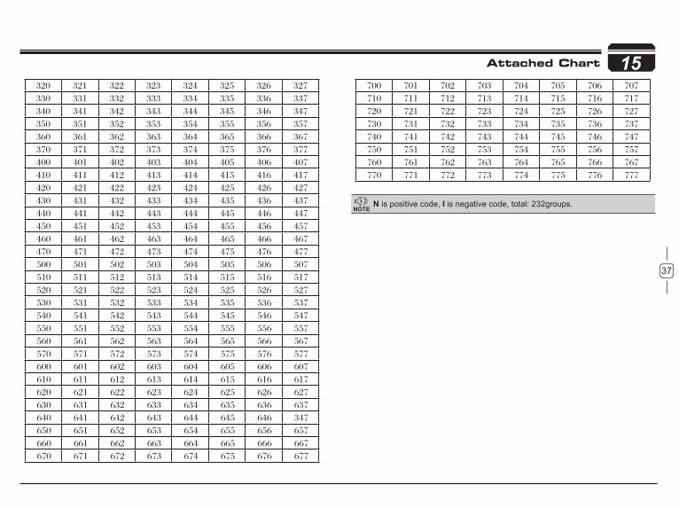
Attached Chart
50 groups CTCSS Tone Frequency(Hz) 1024 groups DCS Code.
37
15
N is positive code, is negative code, total: 232groups.
Attached Chart

