ni 5751/5751b getting started guide - national instruments · getting started guide ni 5751/5751b...
TRANSCRIPT
GETTING STARTED GUIDE
NI 5751/5751B50 MS/s Digitizer Adapter Module
Note Before you begin, complete the software and hardware installationinstructions in your FlexRIO FPGA getting started guide or controller for FlexRIOgetting started guide.
Caution Using the NI 5751/5751B in a manner not described in this documentmay impair the protection the NI 5751/5751B provides.
The NI 5751/5751B is a 50 MS/s, 14-bit high-speed digitizer adapter module designed to workin conjunction with FlexRIO FPGA modules and controllers for FlexRIO. The NI 5751/5751Bfeatures 16 analog input channels and 8 bidirectional digital I/O channels.
This document explains how to install and configure the NI 5751/5751B.
The NI 5751B variant is compatible with all FlexRIO FPGA modules and controllers forFlexRIO. The NI 5751 variant is compatible with the NI PXI-795xR and NI PXIe-796xRFPGA modules only.
Note NI 5751R refers to the combination of your NI 5751/5751B adapter moduleand either a FlexRIO FPGA module or a controller for FlexRIO. NI 5751/5751Brefers to your adapter module only.
Electromagnetic Compatibility GuidelinesThis product was tested and complies with the regulatory requirements and limits forelectromagnetic compatibility (EMC) stated in the product specifications. These requirementsand limits are designed to provide reasonable protection against harmful interference when theproduct is operated in the intended operational electromagnetic environment.
This product is intended for use in industrial locations. However, harmful interference mayoccur in some installations, when the product is connected to a peripheral device or test object,or if the product is used in residential or commercial areas. To minimize interference withradio and television reception and prevent unacceptable performance degradation, install anduse this product in strict accordance with the instructions in the product documentation.
Furthermore, any modifications to the product not expressly approved by National Instrumentscould void your authority to operate it under your local regulatory rules.
Caution To ensure the specified EMC performance, operate this product only withshielded cables and accessories.
Caution To ensure the specified EMC performance, you must install PXI EMCFiller Panels, National Instruments part number 778700-01, in all open chassis slots.You can order a kit of six single slot EMC Filler Panels directly from NI by visitingni.com.
Caution To ensure the specified EMC performance, the length of all I/O cablesmust be no longer than 30 m (100 ft).
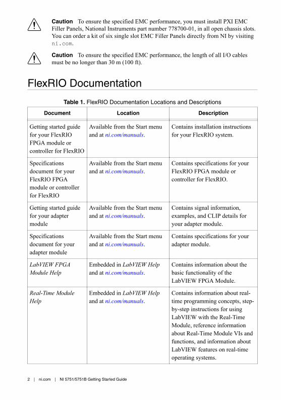
FlexRIO Documentation
Table 1. FlexRIO Documentation Locations and Descriptions
Document Location Description
Getting started guidefor your FlexRIOFPGA module orcontroller for FlexRIO
Available from the Start menuand at ni.com/manuals.
Contains installation instructionsfor your FlexRIO system.
Specificationsdocument for yourFlexRIO FPGAmodule or controllerfor FlexRIO
Available from the Start menuand at ni.com/manuals.
Contains specifications for yourFlexRIO FPGA module orcontroller for FlexRIO.
Getting started guidefor your adaptermodule
Available from the Start menuand at ni.com/manuals.
Contains signal information,examples, and CLIP details foryour adapter module.
Specificationsdocument for youradapter module
Available from the Start menuand at ni.com/manuals.
Contains specifications for youradapter module.
LabVIEW FPGAModule Help
Embedded in LabVIEW Helpand at ni.com/manuals.
Contains information about thebasic functionality of theLabVIEW FPGA Module.
Real-Time ModuleHelp
Embedded in LabVIEW Helpand at ni.com/manuals.
Contains information about real-time programming concepts, step-by-step instructions for usingLabVIEW with the Real-TimeModule, reference informationabout Real-Time Module VIs andfunctions, and information aboutLabVIEW features on real-timeoperating systems.
2 | ni.com | NI 5751/5751B Getting Started Guide
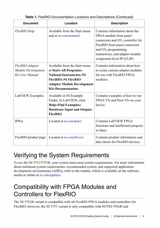
Table 1. FlexRIO Documentation Locations and Descriptions (Continued)
Document Location Description
FlexRIO Help Available from the Start menuand at ni.com/manuals.
Contains information about theFPGA module front panelconnectors and I/O, controller forFlexRIO front panel connectorsand I/O, programminginstructions, and adapter modulecomponent-level IP (CLIP).
FlexRIO AdapterModule DevelopmentKit User Manual
Available from the Start menuat Start»All Programs»National Instruments»NIFlexRIO»NI FlexRIOAdapter Module DevelopmentKit»Documentation.
Contains information about howto create custom adapter modulesfor use with FlexRIO FPGAmodules.
LabVIEW Examples Available in NI ExampleFinder. In LabVIEW, clickHelp»Find Examples»Hardware Input and Output»FlexRIO.
Contains examples of how to runFPGA VIs and Host VIs on yourdevice.
IPNet Located at ni.com/ipnet. Contains LabVIEW FPGAfunctions and intellectual propertyto share.
FlexRIO product page Located at ni.com/flexrio. Contains product information anddata sheets for FlexRIO devices.
Verifying the System RequirementsTo use the NI 5751/5751B, your system must meet certain requirements. For more informationabout minimum system requirements, recommended system, and supported applicationdevelopment environments (ADEs), refer to the readme, which is available on the softwaremedia or online at ni.com/updates.
Compatibility with FPGA Modules andControllers for FlexRIOThe NI 5751B variant is compatible with all FlexRIO FPGA modules and controllers forFlexRIO; however, the NI 5751 variant is only compatible with NI PXI-795xR and
NI 5751/5751B Getting Started Guide | © National Instruments | 3
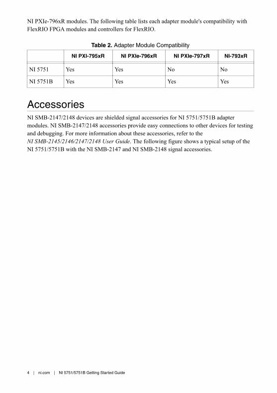
NI PXIe-796xR modules. The following table lists each adapter module's compatibility withFlexRIO FPGA modules and controllers for FlexRIO.
Table 2. Adapter Module Compatibility
NI PXI-795xR NI PXIe-796xR NI PXIe-797xR NI-793xR
NI 5751 Yes Yes No No
NI 5751B Yes Yes Yes Yes
AccessoriesNI SMB-2147/2148 devices are shielded signal accessories for NI 5751/5751B adaptermodules. NI SMB-2147/2148 accessories provide easy connections to other devices for testingand debugging. For more information about these accessories, refer to theNI SMB-2145/2146/2147/2148 User Guide. The following figure shows a typical setup of theNI 5751/5751B with the NI SMB-2147 and NI SMB-2148 signal accessories.
4 | ni.com | NI 5751/5751B Getting Started Guide
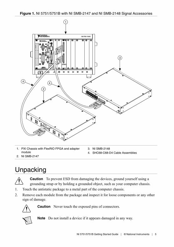
Figure 1. NI 5751/5751B with NI SMB-2147 and NI SMB-2148 Signal Accessories
NI PXI-1042
SMB-2147
Analog Input Accessory
AI 3
AI 7
AI 2
AI 6AI 5
AI 1
AI 0
AI 4
AI 11
AI 15
AI 14
AI 10
AI 13
AI 9
AI 12
AI 8
1
2
3
44
1. PXI Chassis with FlexRIO FPGA and adaptermodule
2. NI SMB-2147
3. NI SMB-21484. SHC68-C68-D4 Cable Assemblies
UnpackingCaution To prevent ESD from damaging the devices, ground yourself using agrounding strap or by holding a grounded object, such as your computer chassis.
1. Touch the antistatic package to a metal part of the computer chassis.2. Remove each module from the package and inspect it for loose components or any other
sign of damage.
Caution Never touch the exposed pins of connectors.
Note Do not install a device if it appears damaged in any way.
NI 5751/5751B Getting Started Guide | © National Instruments | 5
3. Unpack any other items and documentation from the kit.
Store the devices in the antistatic package when they are not in use.
Preparing the EnvironmentEnsure that the environment you are using the NI 5751/5751B in meets the followingspecifications.
Operating temperature (IEC 60068-2-1,IEC 60068-2-2)
0 °C to 55 °C
Operating humidity (IEC 60068-2-56) 10% to 90% RH, noncondensing
Pollution Degree 2
Maximum altitude 2,000 m at 25 °C ambient temperature
Indoor use only.
Note Refer to the NI 5751/5751B Specifications at ni.com/manuals for completespecifications.
Caution Clean the hardware with a soft, nonmetallic brush. Make sure that thehardware is completely dry and free from contaminants before returning it toservice.
Confirming that Measurement & AutomationExplorer (MAX) Recognizes the DeviceUse Measurement & Automation Explorer (MAX) to configure your NI hardware. MAXinforms other programs about which devices reside in the system and how they are configured.MAX is automatically installed with FlexRIO Support.1. Launch MAX by navigating to Start»All Programs»National Instruments»NI MAX or
by clicking the NI MAX desktop icon.2. In the Configuration pane, double-click Devices and Interfaces to see the list of installed
devices. Installed devices appear under the name of their associated chassis.3. (PXI and PXI Express devices only) Expand your Chassis tree item. MAX lists all
devices installed in the chassis. Your default device names may vary.
Note If you do not see your hardware listed, press <F5> to refresh the list ofinstalled devices. If the device is still not listed, power off the system, ensurethe device is correctly installed, and restart.
4. (Controllers for FlexRIO only) Your device appears under the Remote Devices section.
6 | ni.com | NI 5751/5751B Getting Started Guide
Installing the NI 5751/5751BRefer to the getting started guide for your FlexRIO FPGA module or Controller for FlexRIOfor instructions about how to install your FlexRIO system, including the NI 5751/5751B.
CablesNI recommends using the SHC68-C68-D4 cable (part number 196275A-01) with theNI 5751/5751B. This cable connects directly to the analog and digital connectors on theNI 5751/5751B.
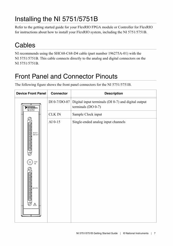
Front Panel and Connector PinoutsThe following figure shows the front panel connectors for the NI 5751/5751B.
Device Front Panel Connector Description
NI 5751
AI 0-15
CLK IN
DI 0-7 DO 0-7
DI 0-7/DO-07 Digital input terminals (DI 0-7) and digital outputterminals (DO 0-7)
CLK IN Sample Clock input
AI 0-15 Single-ended analog input channels
NI 5751/5751B Getting Started Guide | © National Instruments | 7
Caution To avoid permanent damage to the NI 5751/5751B, disconnect all signalsconnected to the NI 5751/5751B before powering down the module, and connectsignals only after the adapter module has been powered on by the FlexRIO FPGAmodule or controller for FlexRIO.
Caution Connections that exceed any of the maximum ratings of any connector onthe NI 5751/5751B can damage the device and the chassis. NI is not liable for anydamage resulting from such connections.
Pinout and Signal InformationThe following figure shows the pinout for the VHDCI connector.
8 | ni.com | NI 5751/5751B Getting Started Guide
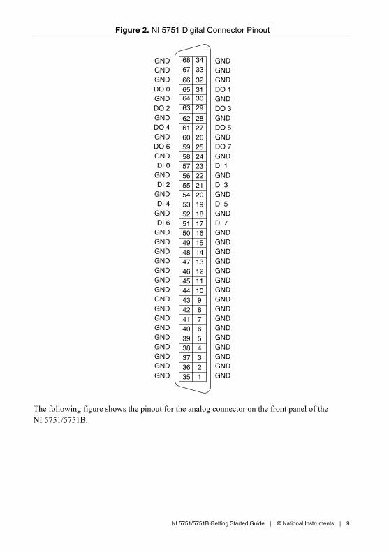
Figure 2. NI 5751 Digital Connector Pinout
GNDGNDGND
GND
GND
GNDGNDGND
GND
GND
GND
GND
GND
GND
GNDGND
GND
GND
GND
GND
GND
GND
GND
GNDDO 1
GND
GND
GNDGNDGND
GND
DO 3
DO 5
DO 7
DI 1
DI 3
DI 5
DI 7
DO 0
GNDGNDGND
GND
GNDGNDGND
GND
GNDGNDGND
GND
GNDGNDGNDGND
DO 2
DO 4
DO 6
DI 0
DI 2
DI 4
DI 6GND
GND
GND
GND
GND
GND
35 36 37 38 39 40 41 42 43 44 45 46 47 48 49 50 51 52 53 54 55 56 57 58 59 60 61 62
63 64 65 66
67 68
1 2 3 4 5 6 7 8 9 10 11 12 13 14 15 16 17 18 19 20 21 22 23 24 25 26 27 28
29 30 31 32
33 34
The following figure shows the pinout for the analog connector on the front panel of theNI 5751/5751B.
NI 5751/5751B Getting Started Guide | © National Instruments | 9
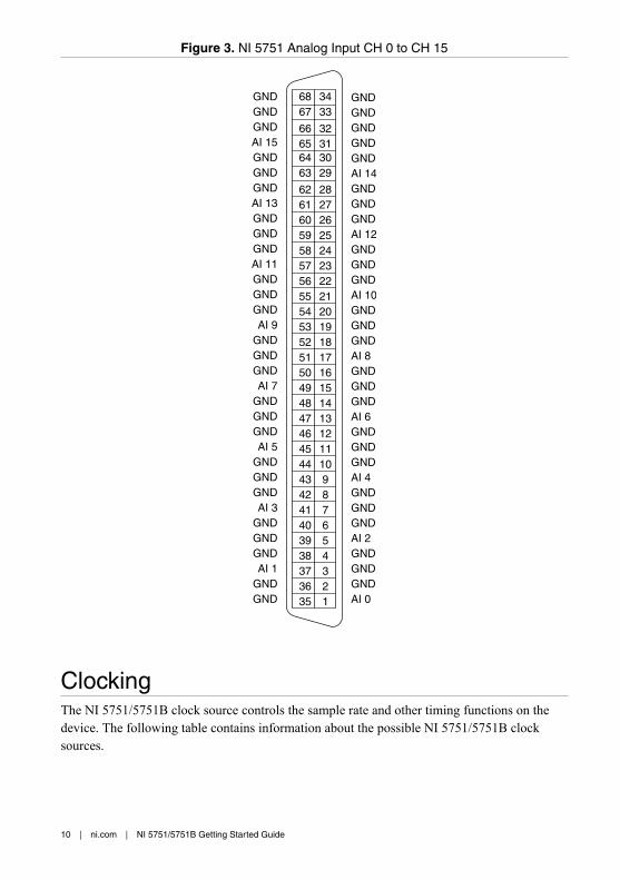
Figure 3. NI 5751 Analog Input CH 0 to CH 15
35 36 37 38 39 40 41 42 43 44 45 46 47 48 49 50 51 52 53 54 55 56 57 58 59 60 61 62
63 64 65 66
67 68
1 2 3 4 5 6 7 8 9 10 11 12 13 14 15 16 17 18 19 20 21 22 23 24 25 26 27 28
29 30 31 32
33 34
GNDAI 0
GNDGND
GND
GND
GNDGNDGND
GNDGND
GNDGND
GND
GND
AI 2GNDGND
AI 4GND
AI 6GND
AI 8
AI 10
GND
AI 12
AI 14
GND
GNDGNDGND
GNDGND
GND
GND
GND
GND
GNDGND
GNDGNDGND
GND
GNDGNDGND
GND
GND
AI 1
AI 3
AI 5
AI 7
AI 9
AI 11
AI 13
AI 15
GND
GNDGNDGND
GNDGND
GNDGNDGND
GNDGND
GND
ClockingThe NI 5751/5751B clock source controls the sample rate and other timing functions on thedevice. The following table contains information about the possible NI 5751/5751B clocksources.
10 | ni.com | NI 5751/5751B Getting Started Guide
Table 3. Sample Clock Sources
Clock Notes FrequencyRange
50 MHzonboard clock
— 30 MHz to50 MHz
Sync Clock(DStarA)
Sync Clock (DStarA) is only available on NI PXIExpress FlexRIO FPGA modules (such as theNI PXIe-796xR). DStarA is not available on NI-793xRcontrollers for FlexRIO or NI PXI FlexRIO FPGAmodules (such as the NI PXI-795xR). On PXI Expressmodules, Sync Clock is driven by the DStarA from thePXI/PXIe backplane.
If you change the frequency of Sync Clock (DStarA) orCLK IN (when used as the Sample Clock), you mustassert Force Initialization.
CLK IN (frontpanel SMB)
If you change the frequency of Sync Clock (DStarA) orCLK IN (when used as the Sample Clock), you mustassert Force Initialization. For more information, referto the FlexRIO Help.
Related InformationFor more information about clock sources, refer to the FlexRIO Help.
Block DiagramThe following figure shows the NI 5751/5751B block diagram and signal flow.
NI 5751/5751B Getting Started Guide | © National Instruments | 11
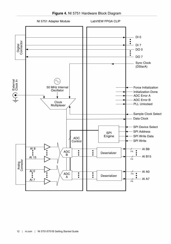
Figure 4. NI 5751 Hardware Block Diagram
I16
I16
I16
AI A0
AI A7
Anal
og
Con
nect
or
ADCB
ADCA
Deserializer
I16
AI B8
AI B15
Deserializer
AI 0
AI 7
AI 8
AI 15
DI 0
DI 7DO 0
Sync Clock (DStarA)
DO 7
Ext
erna
lC
lock
In
Clock Multiplexer
50 MHz InternalOscillator
Dig
ital
Con
nect
or
Sample Clock Select
SPI Write
SPI Device Select
SPI Address
SPI Write Data
Force InitializationInitialization Done
PLL Unlocked
ADC Error AADC Error B
SPIEngine
NI 5751 Adapter Module LabVIEW FPGA CLIP
Data Clock
ADCControl
12 | ni.com | NI 5751/5751B Getting Started Guide
Component-Level Intellectual Property (CLIP)The LabVIEW FPGA Module includes component-level intellectual property (CLIP) for HDLIP integration. FlexRIO devices support two types of CLIP: user-defined and socketed.• User-defined CLIP allows you to insert HDL IP into an FPGA target, enabling VHDL
code to communicate directly with an FPGA VI.• Socketed CLIP provides the same IP integration of the user-defined CLIP, but it also
allows the CLIP to communicate directly with circuitry external to the FPGA. Adaptermodule socketed CLIP allows your IP to communicate directly with both the FPGA VIand the external adapter module connector interface.
The FlexRIO adapter module ships with socketed CLIP items that add module I/O to theLabVIEW project.
NI 5751 CLIPThe NI 5751/5751B ships with the following CLIP items:1. NI 5751 CLIP—The NI 5751 CLIP provides access to 16 analog input channels, eight
digital input lines, and eight digital output lines. This CLIP also contains a SPI interfaceto program the ADC registers.In the NI 5751 CLIP, each Sample Clock cycle generates a sample from the analog inputchannels. Three clock sources are available and are selectable using the Sample ClockSelect control. The default clock source is the 50 MHz onboard oscillator. Other clocksources available are DStarA through IOModSyncClock and an external clock throughthe front panel SMB connector. This CLIP only supports external Sample Clock ratesfrom 30 MHz to 50 MHz. Each 14-bit sample is output to LabVIEW as an I16 data type.The 14-bit data is left-justified and padded with two zeros in the LSBs. The data isclocked out of the CLIP on the Data Clock signal.
2. NI 5751 Multidevice Synchronization CLIP—The NI 5751 MultideviceSynchronization CLIP provides access to 16 analog input channels, eight digital inputlines, and eight digital output lines. This CLIP also contains a SPI interface to programthe ADC registers. Use this CLIP for applications that require synchronization acrossmultiple NI 5751 modules.In the NI 5751 Multidevice Synchronization CLIP, each Sample Clock cycle generates asample from the analog input channels. DStarA is the only Sample Clock that is routed.This CLIP only supports external Sample Clock rates from 30 MHz to 50 MHz. Each 14-bit sample is output to LabVIEW as an I16 data type. The 14-bit data is left-justified andpadded with two zeros in the LSBs. DStarA is required to be routed to the CLIP fromLabVIEW FPGA. The data is clocked out of the CLIP on the Data Clock signal.
Related InformationRefer to the FlexRIO Help for more information about FlexRIO CLIP items, how to configurethe NI 5751/5751B with a socketed CLIP, and for a list of available socketed CLIP signals
NI 5751/5751B Getting Started Guide | © National Instruments | 13
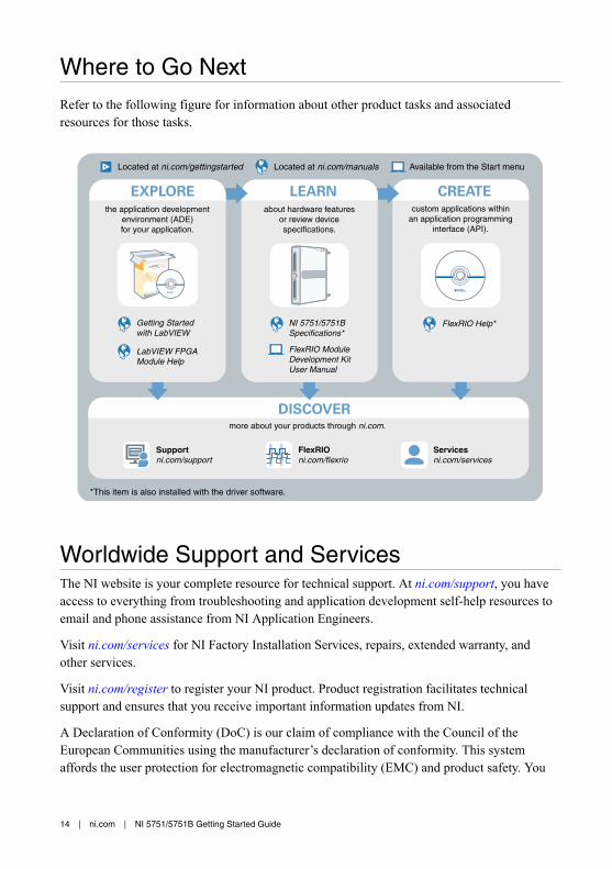
Where to Go Next
Refer to the following figure for information about other product tasks and associatedresources for those tasks.
custom applications withinan application programming
interface (API).
about hardware featuresor review devicespecifications.
more about your products through ni.com.
the application developmentenvironment (ADE)for your application.
*This item is also installed with the driver software.
Supportni.com/support
FlexRIOni.com/flexrio
Servicesni.com/services
Located at ni.com/manualsLocated at ni.com/gettingstarted Available from the Start menu
FlexRIO Help* Getting Startedwith LabVIEW
LabVIEW FPGAModule Help
NI 5751/5751BSpecifications*
FlexRIO ModuleDevelopment KitUser Manual
DISCOVER
CREATELEARNEXPLORE
Worldwide Support and ServicesThe NI website is your complete resource for technical support. At ni.com/support, you haveaccess to everything from troubleshooting and application development self-help resources toemail and phone assistance from NI Application Engineers.
Visit ni.com/services for NI Factory Installation Services, repairs, extended warranty, andother services.
Visit ni.com/register to register your NI product. Product registration facilitates technicalsupport and ensures that you receive important information updates from NI.
A Declaration of Conformity (DoC) is our claim of compliance with the Council of theEuropean Communities using the manufacturer’s declaration of conformity. This systemaffords the user protection for electromagnetic compatibility (EMC) and product safety. You
14 | ni.com | NI 5751/5751B Getting Started Guide
can obtain the DoC for your product by visiting ni.com/certification. If your product supportscalibration, you can obtain the calibration certificate for your product at ni.com/calibration.
NI corporate headquarters is located at 11500 North Mopac Expressway, Austin, Texas,78759-3504. NI also has offices located around the world. For telephone support in the UnitedStates, create your service request at ni.com/support or dial 1 866 ASK MYNI (275 6964). Fortelephone support outside the United States, visit the Worldwide Offices section of ni.com/niglobal to access the branch office websites, which provide up-to-date contact information,support phone numbers, email addresses, and current events.
NI 5751/5751B Getting Started Guide | © National Instruments | 15

Refer to the NI Trademarks and Logo Guidelines at ni.com/trademarks for information on NI trademarks. Other product andcompany names mentioned herein are trademarks or trade names of their respective companies. For patents covering NIproducts/technology, refer to the appropriate location: Help»Patents in your software, the patents.txt file on your media, or theNational Instruments Patent Notice at ni.com/patents. You can find information about end-user license agreements (EULAs)and third-party legal notices in the readme file for your NI product. Refer to the Export Compliance Information at ni.com/legal/export-compliance for the NI global trade compliance policy and how to obtain relevant HTS codes, ECCNs, and otherimport/export data. NI MAKES NO EXPRESS OR IMPLIED WARRANTIES AS TO THE ACCURACY OF THE INFORMATIONCONTAINED HEREIN AND SHALL NOT BE LIABLE FOR ANY ERRORS. U.S. Government Customers: The data contained inthis manual was developed at private expense and is subject to the applicable limited rights and restricted data rights as set forthin FAR 52.227-14, DFAR 252.227-7014, and DFAR 252.227-7015.
© 2015 National Instruments. All rights reserved.
374702A-01 Oct15