ngnp with hydrogen production preconceptual design studies ... documents/areva/12-9052076... ·...
TRANSCRIPT

AREVA NP Inc.
NGNP with Hydrogen ProductionPreconceptual Design Studies Report
Executive Summary
June 2007
BEA Contract No. 000 60209
Disclaimer
This report was prepared as an account of work sponsored by an agency of the United States Government. Neither the United States Government nor any agency thereof, nor any of their employees, nor their contractors and subcontractors, makes any warranty, express or implied, or assumes any legal liability or responsibility for the accuracy, completeness, or usefulness of any information, apparatus, product, or process disclosed, or represents that its use would not infringe privately owned rights. Reference herein to any specific commercial product, process, or service by trade name, trademark, manufacturer, or otherwise does not necessarily constitute or imply its endorsement, recommendation, or favoring by the United States Government or any agency thereof. The views and opinions of authors expressed herein do not necessarily state or reflect those of the United States Government or any agency thereof.
Document No. 12-9052076-001
NGNP PCDSR Executive Summary Document No. 12-9052076-001
AREVA NP Inc., an AREVA and Siemens company Page 2
Record of Revisions
Revision Date Pages/Sections Changed Brief Description 000 6/05/2007 None. Original Issue 001 6/21/2007 2.3, 2.4, 3.1, 4.2, 5.1, 5.2,
7.2.1Miscellaneous editorial corrections
001 6/21/2007 7.3 Discussion of overall project risk expanded 001 6/21/2007 9.4, 9.7 Conclusions regarding risk were expanded

NGNP PCDSR Executive Summary Document No. 12-9052076-001
AREVA NP Inc., an AREVA and Siemens company Page 3
Table of Contents Page
RECORD OF REVISIONS..................................................................................................................2
LIST OF TABLES ...............................................................................................................................5
LIST OF FIGURES .............................................................................................................................5
1.0 INTRODUCTION.....................................................................................................................6 1.1 NGNP Preconceptual Design Studies Objectives........................................................6 1.2 Scope of Work .............................................................................................................6 1.3 AREVA NGNP Team ...................................................................................................7
2.0 NGNP PRECONCEPTUAL DESIGN SPECIAL STUDIES .....................................................8 2.1 Reactor Type Comparison Study.................................................................................8 2.2 Prototype Power Level Study.......................................................................................8 2.3 Power Conversion System Study ................................................................................9 2.4 Primary and Secondary Cycle Concept Study...........................................................10
3.0 REFERENCE NGNP PRECONCEPTUAL DESIGN .............................................................12 3.1 Nuclear System Arrangement....................................................................................12 3.2 Nuclear Support Systems ..........................................................................................15 3.3 Power Conversion System Arrangement...................................................................16 3.4 Heat Transport Loop ..................................................................................................18 3.5 Hydrogen Production Plant ........................................................................................18 3.6 Plant Layout ...............................................................................................................18
4.0 FUEL SUPPLY STRATEGY..................................................................................................21 4.1 Fuel Strategy..............................................................................................................21 4.2 Fuel Design................................................................................................................22 4.3 Fuel Qualification Plan ...............................................................................................23 4.4 Fuel Fabrication Plan .................................................................................................23
5.0 SAFETY AND LICENSING ...................................................................................................27 5.1 Safety.........................................................................................................................27 5.2 Licensing....................................................................................................................28
5.2.1 Prototype Licensing ......................................................................................28 5.2.2 Commercial Plant Licensing .........................................................................28

NGNP PCDSR Executive Summary Document No. 12-9052076-001
Table of Contents (continued)
Page
AREVA NP Inc., an AREVA and Siemens company Page 4
5.2.3 Regulatory Requirements Development .......................................................28
6.0 PLANNING FOR COMPLETION OF NGNP PROJECT .......................................................29 6.1 Cost and Economics ..................................................................................................29 6.2 Project Schedule........................................................................................................29
7.0 RISK MANAGEMENT AND R&D ..........................................................................................32 7.1 Project Risk Management..........................................................................................32
7.1.1 Key Risks ......................................................................................................32 7.2 Research and Development Needs ...........................................................................33
7.2.1 Approach to Define R&D Needs ...................................................................33 7.2.2 R&D Needs ...................................................................................................34
7.3 Overall Risk/R&D Implications ...................................................................................34
8.0 NEXT STEPS........................................................................................................................36 8.1 Steam Cycle Concept Evaluation ..............................................................................36 8.2 Demonstration Plant Size Confirmation .....................................................................37
9.0 CONCLUSIONS/RECOMMENDATIONS..............................................................................40 9.1 Special Study Conclusions ........................................................................................40 9.2 Design Adaptation Conclusions .................................................................................40 9.3 Hydrogen Production Conclusions.............................................................................41 9.4 Risk and R&D Conclusions........................................................................................41 9.5 Cost and Economic Conclusions ...............................................................................41 9.6 Recommended Future Studies ..................................................................................42 9.7 Overall Conclusion.....................................................................................................42

NGNP PCDSR Executive Summary Document No. 12-9052076-001
AREVA NP Inc., an AREVA and Siemens company Page 5
List of Tables Page
Table 3-1: Normal Operating Parameters..............................................................................................14 Table 3-2: Main Parameters of the PCS system....................................................................................18 Table 4-1: General Fuel Quality Requirements .....................................................................................22 Table 8-1: Suggested NGNP Future Studies.........................................................................................39
List of Figures Page
Figure 1-1: AREVA NGNP Team Organization .......................................................................................7 Figure 3-1: AREVA HTR Indirect Cycle NGNP Schematic ....................................................................13 Figure 3-2: Internal Structure of TRISO Coated Fuel Particle ...............................................................14 Figure 3-3: Core Layout .........................................................................................................................15 Figure 3-4: Vessels Arrangement ..........................................................................................................16 Figure 3-5: PCS Configuration...............................................................................................................17 Figure 3-6: Plant Layout.........................................................................................................................20 Figure 4-1: NGNP Fuel Program Schedule ...........................................................................................26 Figure 6-1: NGNP High Level Schedule ................................................................................................30

NGNP PCDSR Executive Summary Document No. 12-9052076-001
AREVA NP Inc., an AREVA and Siemens company Page 6
1.0 INTRODUCTION This report summarizes the Next Generation Nuclear Plant (NGNP) preconceptual design studies performed by the AREVA NGNP team for the Battelle Energy Alliance (BEA), the Management & Operating Contractor of the Idaho National Laboratory (INL) as part of the Department of Energy’s (DOE) NGNP Project. These studies are documented more fully in the AREVA report NGNP with Hydrogen Production Preconceptual Design Studies Report (document 12-9051191).
1.1 NGNP Preconceptual Design Studies Objectives DOE’s NGNP Project, as authorized by the Energy Policy Act of 2005, will develop and demonstrate a first-of-a-kind very-high-temperature gas-cooled nuclear system with the capability to generate electrical power and demonstrate nuclear hydrogen production. The overall objectives of this project include:
� Development and implementation of technology required for the NGNP mission � Demonstration of a commercially scaleable prototype nuclear heat source, hydrogen production facility,
and power generating system � Development of a regulatory framework (requirements and process) for licensing the NGNP prototype
and for future HTR commercialization � Fostering rebuilding of U.S. nuclear industrial infrastructure
The purpose of INL in authorizing the preconceptual design studies summarized herein is two-fold:
1. Assist INL in focusing the technical scope and priorities of research & development activities for the NGNP.
2. Provide INL a basis for subsequent development of the technical and functional specifications for the prototype facilities for NGNP.
The preconceptual design studies as performed by AREVA within the authorized work scope and as reported herein are also consistent with the corresponding elements of the Phase I scope of work defined for the NGNP Project in the Energy Policy Act of 2005.
1.2 Scope of Work The Scope of Work assigned to the AREVA NGNP team consisted of the preparation of a preconceptual design studies report on the adaptation of AREVA’s ANTARES HTR concept to NGNP requirements and four supporting special studies. Because BEA/INL issued multiple awards, the final scope of work reported on herein is a reduced scope of work relative to the initial scope of work requested by BEA/INL in their Statement of Work No. 3963, “Preconceptual Engineering Services for the Next Generation Nuclear Plant with Hydrogen Production,” (Project No. 23843, July 26, 2006).
Key work elements developed within the framework of the scope of work are listed below: � NGNP System Requirements Manual � Develop NGNP preconceptual design � Four supporting special studies:
� Reactor Type Comparison Study � Prototype Power Level Study � Power Conversion System Study � Primary and Secondary Cycle Concept Study

NGNP PCDSR Executive Summary Document No. 12-9052076-001
AREVA NP Inc., an AREVA and Siemens company Page 7
� Identification of R&D needs and project risks � Cost and economic analysis � Project schedule � Preconceptual Design Studies Report
Of the above special studies, only the results of the reactor power level and primary-secondary systems study are factored into the NGNP preconceptual design. The direction to adapt the ANTARES indirect cycle CCGT concept to the NGNP made the results of the reactor type and power conversion system moot relative to the preconceptual design, nevertheless, they were performed due to the valuable insights they would provide BEA/INL for the NGNP conceptual design.
1.3 AREVA NGNP Team AREVA, as the lead contractor for this work scope, has the overall project responsibility. In support of the NGNP preconceptual design work, AREVA assembled a team of sub-contractor companies with the key technical competencies needed to cover the full breadth and scope of the NGNP project including final design, construction, and operations.
The AREVA NGNP Team includes Burns & Roe, Washington Group International, BWXT, Dominion Engineering, Air Products, Hamilton-Sundstrand-Rocketdyne, Mitsubishi Heavy Industries (MHI), NovaTech, and Entergy. The team organization is show graphically on Figure 1-1 below
PROJECTMANAGER
SYSTEMINTEGRATION
SITE & PLANTSTUDIES
NUCLEAR HEATSOURCE
QUALITYASSURANCE
PROJECTENGINEER
CONTRACTADMINISTRATIION
HYDROGEN PLANT& PROCESS HEAT
POWERCONVERSION
FUEL& HEAVYCOMPONENTS
PROCESS HEATTRANSFER
HYDROGENPRODUCTION
POWER CONVERSION SPECIAL STUDY
POWER CONVERSIONSYSTEM
AREVAAir Products
BWXTHamilton-Sundstrand Rocketdyne
WGI
Dominion Engineering
Burns & Roe
MHI
UTILITYPERSPECTIVE
ENTERGY
PROJECTMANAGER
SYSTEMINTEGRATION
SITE & PLANTSTUDIES
NUCLEAR HEATSOURCE
QUALITYASSURANCE
PROJECTENGINEER
CONTRACTADMINISTRATIION
HYDROGEN PLANT& PROCESS HEAT
POWERCONVERSION
FUEL& HEAVYCOMPONENTS
PROCESS HEATTRANSFER
HYDROGENPRODUCTION
POWER CONVERSION SPECIAL STUDY
POWER CONVERSIONSYSTEM
PROJECTMANAGER
SYSTEMINTEGRATION
SITE & PLANTSTUDIES
NUCLEAR HEATSOURCE
QUALITYASSURANCE
PROJECTENGINEER
CONTRACTADMINISTRATIION
HYDROGEN PLANT& PROCESS HEAT
POWERCONVERSION
FUEL& HEAVYCOMPONENTS
PROCESS HEATTRANSFER
HYDROGENPRODUCTION
POWER CONVERSION SPECIAL STUDY
POWER CONVERSIONSYSTEM
AREVAAir Products
BWXTHamilton-Sundstrand Rocketdyne
WGI
Dominion Engineering
Burns & Roe
MHI
UTILITYPERSPECTIVE
ENTERGY
Figure 1-1: AREVA NGNP Team Organization
NGNP PCDSR Executive Summary Document No. 12-9052076-001
AREVA NP Inc., an AREVA and Siemens company Page 8
2.0 NGNP PRECONCEPTUAL DESIGN SPECIAL STUDIES The DOE-AREVA work plan governing NGNP preconceptual work specified that the NGNP design be an adaptation of ANTARES, the AREVA HTR concept. ANTARES is an indirect cycle, 600 MWth prismatic graphite block reactor that, via an intermediate heat exchanger, is coupled to a combined cycle gas turbine (CCGT) power conversion system. In this context, the following special studies were performed as part of the preconceptual design scope of work:
1. Reactor Type Comparison Study 2. Prototype Power Level Study 3. Power Conversion System (PCS) Study 4. Primary and Secondary Cycle Concept Study
The results of the power level study and the primary-secondary cycle concept study were integrated into the NGNP preconceptual design. The results of the reactor type comparison study and the PCS study were not integrated into the NGNP design adaptation, because the key design features were set by AREVA’s assigned scope of work. Nevertheless, the results of these studies will provide important input to INL’s overall selection process to establish the NGNP path forward.
The key results from these studies are summarized in the following sections.
2.1 Reactor Type Comparison Study The Reactor Type Comparison Study compared the prismatic reactor concept to the pebble bed reactor concept. The report identified the most important discriminating criteria between the two concepts and provided an assessment of the important technical, operational and maintenance differences and the important developmental risks for each. The report concluded that the prismatic reactor concept best fulfills the needs of the NGNP Program because the prismatic reactor offers the following key advantages over the pebble reactor alternative:
� Higher power level and passive safety
� More useable power (i.e., less parasitic power loss)
� Greater economic potential
� Higher degree of license-ability (i.e., concept previously licensed in the USA (FSV)) � Higher degree of predictability
o Core performance o Less chance of forced outages o Scheduled outages o Greater design flexibility
The prismatic reactor represents the best technological foundation for a commercially attractive, multi-use high temperature reactor concept. Of all the benefits it offers, it is the prismatic reactor’s superior power level capability that makes it most attractive.
The results of the reactor type study were moot relative to the NGNP design adaptation because the reactor type selection was fixed by contract (i.e., it specified the adaptation of the ANTARES design).
2.2 Prototype Power Level Study This special study was conducted to answer the following questions:

NGNP PCDSR Executive Summary Document No. 12-9052076-001
AREVA NP Inc., an AREVA and Siemens company Page 9
� What should be the rated power level of the Nth of a Kind (NOAK) commercial VHTR module?
� Given the desired power level of the commercial VHTR module, what should be the rated power level of the NGNP prototype plant?
� In order to demonstrate commercial scalability of an associated hydrogen production plant, what is the power requirement for a demonstration plant to be associated with the NGNP reactor?
The study examined key discriminating criteria that were selected because of the insight they would provide relative to these many faceted questions. As a result, the study arrived at the following answers to the three study questions:
1. The commercial VHTR module should be designed to operate at 565MWth.
This provides the most economical module size achievable within the passive decay heat removal constraint for the NGNP operating conditions.
2. The NGNP prototype plant should be designed and operated at 100% of the planned commercial power level, that is, 565MWth.
This maximizes the benefit of the NGNP prototype to support technology development, licensing, and component design for direct commercialization, thus minimizing risk for the first commercial plant.
3. The hydrogen generation demonstration loop using the SI process will require 60MWth of process heat and 20MWe from the power conversion system while the hydrogen demonstration loop using the HTE process will require only 1.2 MWth of process heat and 5MWe from the power conversion system
This represents the best balance between the current state of hydrogen process technology, the expected state of the technology when the NGNP prototype is scheduled to enter service, and the design to step directly to full scale commercial deployment following demonstration in the NGNP.
As stated above, building the NGNP prototype at full size minimizes the deployment risk and difficulty for the first commercial plant. However, in doing so, it places greater risk and effort on the NGNP. Therefore, it might be beneficial to confirm the initial study results in a more detailed evaluation of the partitioning of required R&D, risk, and design effort between the prototype plant and the first commercial plant. Such a study is recommended as part of the future studies identified later in this report. The recommended study would evaluate these factors in greater detail than was possible in the initial study and would also consider the impact on prototype deployment schedule and program political sustainability.
2.3 Power Conversion System Study The Power Conversion System (PCS) Study examined two closely related questions; namely:
� What type of PCS should be used? o Brayton cycle o Rankine cycle o Combined cycle gas turbine o Supercritical CO2 (SCCO2) o Cascaded Supercritical CO2 (SCCO2)
� How should the PCS be coupled to the reactor? o Directly o Indirectly
Considerations driving the selection are system performance; flexibility and operability; adaptability of existing technology; technology maturity; deployment schedule, system costs including development, capital, and operation and maintenance; reliability; availability; and maintainability.
Further, the relationship between the NGNP and a commercial plant must be considered. The NGNP must serve both electricity (PCS) and the hydrogen plant. The NGNP conditions are driven largely by hydrogen process.
NGNP PCDSR Executive Summary Document No. 12-9052076-001
AREVA NP Inc., an AREVA and Siemens company Page 10
However, the commercial electricity plant would likely have different conditions. Also, the optimum PCS for the commercial plant may not be the same as the optimum PCS for the NGNP.
The best PCS cycle for the NGNP is dependent upon the worth of cycle efficiency and the importance of cycle maturity, especially as it relates to achieving NGNP startup in 2018:
1. Steam-Rankine cycles are the most mature, but the cost of steam turbines and supporting equipment reduces their attractiveness. The supercritical steam cycle with two reheats is the best steam cycle option.
2. The supercritical CO2 cycles are very promising for longer term applications. The need for development is a disadvantage for near term applications. The ability to arrange them in a cascaded configuration for large �T applications is a plus.
3. The Brayton cycles are marginal in cost and performance. Operation and maintenance difficulties from radioactive contamination of the PCS are a negative for the direct Brayton cycle. The loss of efficiency as a result of the temperature drop across the IHX reduces the attractiveness of the indirect Brayton cycle. Further, because of the relative unattractiveness of the Brayton cycles when compared to the supercritical CO2 cycles brings further pursuit of Brayton cycle development into question.
4. The CCGT performance is good but the costs, added complexity and lower maturity when compared with Steam-Rankine cycles reduces its attractiveness. The potential for long term economic advantage from small efficiency differences when compared to the supercritical steam-Rankine cycle or the indirect Brayton cycle may swing the advantage to the CCGT.
Based on the above results, the steam-Rankine cycle (possibly supercritical) is clearly the best fit for a near term applications such as the NGNP. It provides high efficiency electricity production and can readily service near term process heat markets. Moreover, it is a familiar technology that is directly coupled to reactor system.
The results of the PCS Study were not integrated into the design adaptation because the PCS concept was fixed by contract to the adaptation of the ANTARES design.
However, as noted in the discussion of future studies later in this summary report, a thorough evaluation of the potential to apply a steam cycle design to the NGNP mission is strongly recommended. This evaluation should include the development of a preconceptual steam cycle design based on the prismatic HTR and a comparative evaluation of the R&D requirements and technical risk of a steam cycle concept compared to the reference VHTR concept.
2.4 Primary and Secondary Cycle Concept Study The Primary and Secondary Cycle Concept Study establishes the basic NGNP operating parameters for the primary and secondary cycle and establishes the reference configuration for NGNP preconceptual design adaptation. Furthermore, it enhances the basis for NGNP Design Baseline.
The main objective of the study is to answer the following questions: � What is the recommended reactor Tout? � What is the recommended reactor Tin? � What should the system configuration be? And,
o Should the heat supply to the hydrogen process be in parallel or in series with power generating system?
o How many loops should the system have? � What is the secondary side Thot and Tcold? � What are the primary and secondary system pressures?
NGNP PCDSR Executive Summary Document No. 12-9052076-001
AREVA NP Inc., an AREVA and Siemens company Page 11
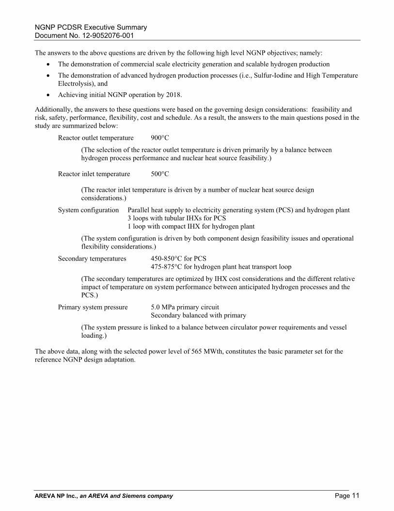
The answers to the above questions are driven by the following high level NGNP objectives; namely: � The demonstration of commercial scale electricity generation and scalable hydrogen production � The demonstration of advanced hydrogen production processes (i.e., Sulfur-Iodine and High Temperature
Electrolysis), and � Achieving initial NGNP operation by 2018.
Additionally, the answers to these questions were based on the governing design considerations: feasibility and risk, safety, performance, flexibility, cost and schedule. As a result, the answers to the main questions posed in the study are summarized below:
Reactor outlet temperature 900°C
(The selection of the reactor outlet temperature is driven primarily by a balance between hydrogen process performance and nuclear heat source feasibility.)
Reactor inlet temperature 500°C
(The reactor inlet temperature is driven by a number of nuclear heat source design considerations.)
System configuration Parallel heat supply to electricity generating system (PCS) and hydrogen plant 3 loops with tubular IHXs for PCS 1 loop with compact IHX for hydrogen plant
(The system configuration is driven by both component design feasibility issues and operational flexibility considerations.)
Secondary temperatures 450-850°C for PCS 475-875°C for hydrogen plant heat transport loop
(The secondary temperatures are optimized by IHX cost considerations and the different relative impact of temperature on system performance between anticipated hydrogen processes and the PCS.)
Primary system pressure 5.0 MPa primary circuit Secondary balanced with primary
(The system pressure is linked to a balance between circulator power requirements and vessel loading.)
The above data, along with the selected power level of 565 MWth, constitutes the basic parameter set for the reference NGNP design adaptation.
NGNP PCDSR Executive Summary Document No. 12-9052076-001
AREVA NP Inc., an AREVA and Siemens company Page 12
3.0 REFERENCE NGNP PRECONCEPTUAL DESIGN The NGNP is aimed at producing both electricity and hydrogen in a cogeneration mode. The plant can operate in an all-electric mode and it can also produce hydrogen and electricity simultaneously. The NGNP is envisioned as a flexible demonstration and R&D facility, and it is expected that multiple high temperature hydrogen production processes and components will be demonstrated.
The NGNP plant consists of the following:
� Nuclear Heat Source
� Power Conversion System
� High Temperature Heat Transport Loop
� Hydrogen Production Plant
� Site facilities
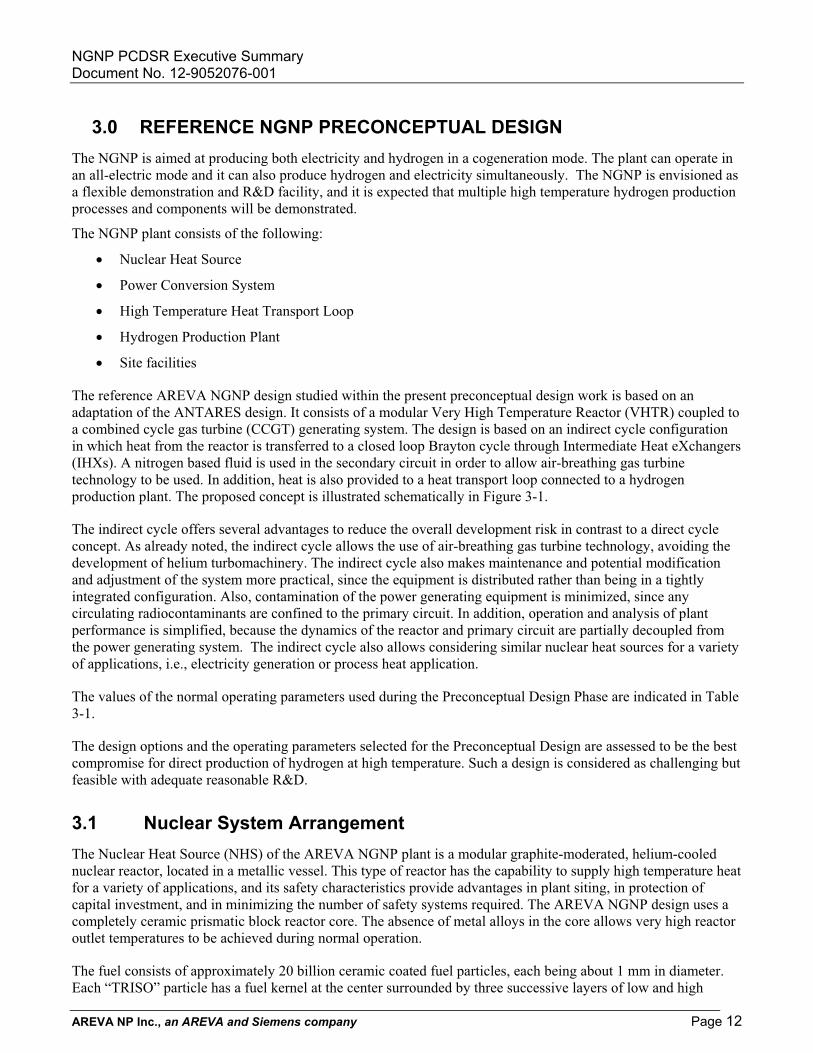
The reference AREVA NGNP design studied within the present preconceptual design work is based on an adaptation of the ANTARES design. It consists of a modular Very High Temperature Reactor (VHTR) coupled to a combined cycle gas turbine (CCGT) generating system. The design is based on an indirect cycle configuration in which heat from the reactor is transferred to a closed loop Brayton cycle through Intermediate Heat eXchangers (IHXs). A nitrogen based fluid is used in the secondary circuit in order to allow air-breathing gas turbine technology to be used. In addition, heat is also provided to a heat transport loop connected to a hydrogen production plant. The proposed concept is illustrated schematically in Figure 3-1.
The indirect cycle offers several advantages to reduce the overall development risk in contrast to a direct cycle concept. As already noted, the indirect cycle allows the use of air-breathing gas turbine technology, avoiding the development of helium turbomachinery. The indirect cycle also makes maintenance and potential modification and adjustment of the system more practical, since the equipment is distributed rather than being in a tightly integrated configuration. Also, contamination of the power generating equipment is minimized, since any circulating radiocontaminants are confined to the primary circuit. In addition, operation and analysis of plant performance is simplified, because the dynamics of the reactor and primary circuit are partially decoupled from the power generating system. The indirect cycle also allows considering similar nuclear heat sources for a variety of applications, i.e., electricity generation or process heat application.
The values of the normal operating parameters used during the Preconceptual Design Phase are indicated in Table 3-1.
The design options and the operating parameters selected for the Preconceptual Design are assessed to be the best compromise for direct production of hydrogen at high temperature. Such a design is considered as challenging but feasible with adequate reasonable R&D.
3.1 Nuclear System Arrangement The Nuclear Heat Source (NHS) of the AREVA NGNP plant is a modular graphite-moderated, helium-cooled nuclear reactor, located in a metallic vessel. This type of reactor has the capability to supply high temperature heat for a variety of applications, and its safety characteristics provide advantages in plant siting, in protection of capital investment, and in minimizing the number of safety systems required. The AREVA NGNP design uses a completely ceramic prismatic block reactor core. The absence of metal alloys in the core allows very high reactor outlet temperatures to be achieved during normal operation.
The fuel consists of approximately 20 billion ceramic coated fuel particles, each being about 1 mm in diameter. Each “TRISO” particle has a fuel kernel at the center surrounded by three successive layers of low and high
NGNP PCDSR Executive Summary Document No. 12-9052076-001
AREVA NP Inc., an AREVA and Siemens company Page 13
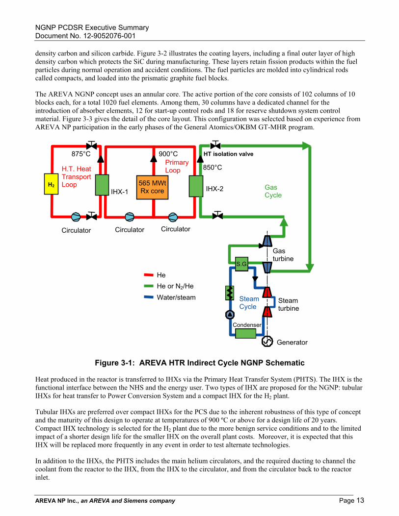
density carbon and silicon carbide. Figure 3-2 illustrates the coating layers, including a final outer layer of high density carbon which protects the SiC during manufacturing. These layers retain fission products within the fuel particles during normal operation and accident conditions. The fuel particles are molded into cylindrical rods called compacts, and loaded into the prismatic graphite fuel blocks.
The AREVA NGNP concept uses an annular core. The active portion of the core consists of 102 columns of 10 blocks each, for a total 1020 fuel elements. Among them, 30 columns have a dedicated channel for the introduction of absorber elements, 12 for start-up control rods and 18 for reserve shutdown system control material. Figure 3-3 gives the detail of the core layout. This configuration was selected based on experience from AREVA NP participation in the early phases of the General Atomics/OKBM GT-MHR program.
Figure 3-1: AREVA HTR Indirect Cycle NGNP Schematic
Heat produced in the reactor is transferred to IHXs via the Primary Heat Transfer System (PHTS). The IHX is the functional interface between the NHS and the energy user. Two types of IHX are proposed for the NGNP: tubular IHXs for heat transfer to Power Conversion System and a compact IHX for the H2 plant.
Tubular IHXs are preferred over compact IHXs for the PCS due to the inherent robustness of this type of concept and the maturity of this design to operate at temperatures of 900 ºC or above for a design life of 20 years. Compact IHX technology is selected for the H2 plant due to the more benign service conditions and to the limited impact of a shorter design life for the smaller IHX on the overall plant costs. Moreover, it is expected that this IHX will be replaced more frequently in any event in order to test alternate technologies.
In addition to the IHXs, the PHTS includes the main helium circulators, and the required ducting to channel the coolant from the reactor to the IHX, from the IHX to the circulator, and from the circulator back to the reactor inlet.
Condenser
SteamCycle
S.G.
565 MWt Rx core
900°C
He
IHX-2
Circulator
He or N2/He
Gasturbine
Generator
Water/steam
GasCycle
PrimaryLoop
HT isolation valve
850°C
Steamturbine
CirculatorCirculator
H2
875°C
H.T. Heat TransportLoop
IHX-1

NGNP PCDSR Executive Summary Document No. 12-9052076-001
AREVA NP Inc., an AREVA and Siemens company Page 14
Table 3-1: Normal Operating Parameters
Parameter SelectionPrimary Side
Primary Fluid HeliumReactor Power 565 MWt Reactor Outlet Temperature
900°C
Reactor Inlet Temperature
500°C
Primary Coolant Flow Rate
272 kg/s
Primary Coolant Pressure
5 MPa at the circulator outlet
Heat transport to Hydrogen Production Plant Secondary Fluid HeliumHeat Load 60 MWt
Heat transport to Power Conversion System Secondary Fluid Nitrogen/helium mixture
Reference: He 20% - N2 80% in mass Heat Load 578 MWt (all electric mode)
Power Generation Power Generation System
Combined cycle with Brayton topping cycle (secondary circuit) and Rankine bottoming cycle (tertiary steam/water circuit)
Figure 3-2: Internal Structure of TRISO Coated Fuel Particle
NGNP PCDSR Executive Summary Document No. 12-9052076-001
AREVA NP Inc., an AREVA and Siemens company Page 15
Figure 3-3: Core Layout
The NHS systems are contained in a steel vessel system. The reactor pressure vessel is fabricated from Modified 9 Cr – 1 Mo. This alloy provides increased high temperature capability which is compatible with the reactor operating temperatures and provides sufficient margin for off-normal events.
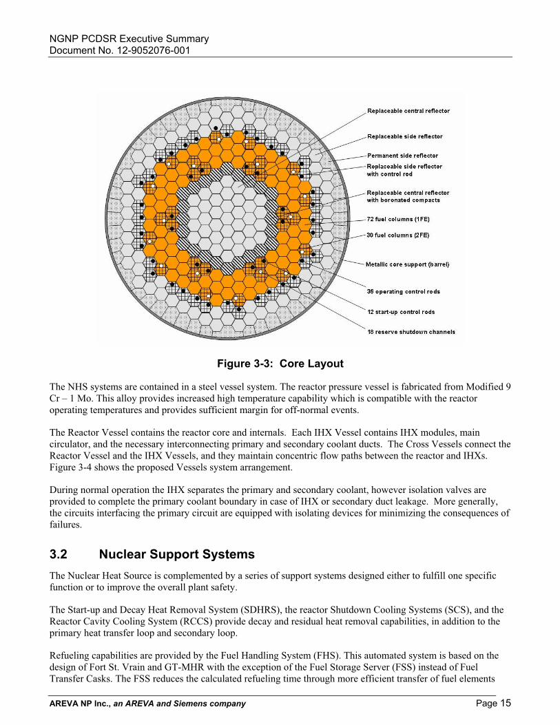
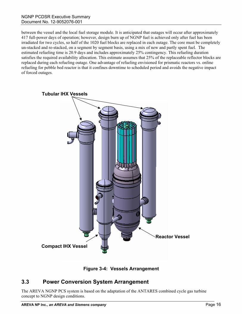
The Reactor Vessel contains the reactor core and internals. Each IHX Vessel contains IHX modules, main circulator, and the necessary interconnecting primary and secondary coolant ducts. The Cross Vessels connect the Reactor Vessel and the IHX Vessels, and they maintain concentric flow paths between the reactor and IHXs. Figure 3-4 shows the proposed Vessels system arrangement.
During normal operation the IHX separates the primary and secondary coolant, however isolation valves are provided to complete the primary coolant boundary in case of IHX or secondary duct leakage. More generally, the circuits interfacing the primary circuit are equipped with isolating devices for minimizing the consequences of failures.
3.2 Nuclear Support Systems The Nuclear Heat Source is complemented by a series of support systems designed either to fulfill one specific function or to improve the overall plant safety.
The Start-up and Decay Heat Removal System (SDHRS), the reactor Shutdown Cooling Systems (SCS), and the Reactor Cavity Cooling System (RCCS) provide decay and residual heat removal capabilities, in addition to the primary heat transfer loop and secondary loop.
Refueling capabilities are provided by the Fuel Handling System (FHS). This automated system is based on the design of Fort St. Vrain and GT-MHR with the exception of the Fuel Storage Server (FSS) instead of Fuel Transfer Casks. The FSS reduces the calculated refueling time through more efficient transfer of fuel elements
NGNP PCDSR Executive Summary Document No. 12-9052076-001
AREVA NP Inc., an AREVA and Siemens company Page 16
between the vessel and the local fuel storage module. It is anticipated that outages will occur after approximately 417 full-power days of operation; however, design burn up of NGNP fuel is achieved only after fuel has been irradiated for two cycles, so half of the 1020 fuel blocks are replaced in each outage. The core must be completely un-stacked and re-stacked, on a segment by segment basis, using a mix of new and partly spent fuel. The estimated refueling time is 20.9 days and includes approximately 25% contingency. This refueling duration satisfies the required availability allocation. This estimate assumes that 25% of the replaceable reflector blocks are replaced during each refueling outage. One advantage of refueling envisioned for prismatic reactors vs. online refueling for pebble bed reactor is that it confines downtime to scheduled period and avoids the negative impact of forced outages.
Figure 3-4: Vessels Arrangement
3.3 Power Conversion System Arrangement The AREVA NGNP PCS system is based on the adaptation of the ANTARES combined cycle gas turbine concept to NGNP design conditions.
Compact IHX Vessel
Reactor Vessel
Tubular IHX Vessels

NGNP PCDSR Executive Summary Document No. 12-9052076-001
AREVA NP Inc., an AREVA and Siemens company Page 17
The Brayton cycle consists of the gas turbine unit (gas turbine, compressor and auxiliaries) and the interconnecting ductwork. The main function of the gas turbine unit is to convert the thermal energy contained in secondary circuit gas exiting the IHX into electrical power. The shaft power generated by the gas turbine drives both the gas compressor and electrical generator. The heat content of the turbine exhaust gas is significant and much of it is transferred to the tertiary steam cycle.
The major components of the tertiary circuit are the Heat Recovery Steam Generator (HRSG), the HP/IP/LP turbine units and the generator, and the condensate system. Superheated high pressure steam from the HRSG goes into high pressure (HP) turbine and then, upon exhaust, is conducted to the HRSG reheating zone. The reheat steam from the HRSG goes to the intermediate pressure (IP) turbine. The exhaust steam from IP turbine is conducted to the low pressure (LP) turbine. The exhaust steam from the LP turbine flows directly to the steam condenser. The condensate system condenses the steam from the LP turbine exhaust and supplies condensate to the feed water heaters.
Pipes are used to transport the hot gas (850ºC) from IHX outlet to gas turbine inlet and from gas turbine outlet to HRSG inlet. Pipes conveying high temperature gas are insulated on the inner surface to keep their operating temperature low.
The PCS configuration considered for NGNP is shown schematically in Figure 3-5.
Figure 3-5: PCS Configuration
This NGNP PCS configuration allows the demonstration of separate turbine generator sets and permits each power unit to be uniquely optimized for its given conditions. Furthermore, in a multiple-module setting, it is feasible to feed a common steam-turbine unit from two or more reactor modules. The NGNP PCS configuration allows the demonstration of the key control features that would be required by such an arrangement.
Table 3-2 provides a summary of the parameters of the PCS system.
With the NHS and PCS system described in sections 3.1 and 3.2, the performance expected for the NGNP for electricity production is the following:

NGNP PCDSR Executive Summary Document No. 12-9052076-001
AREVA NP Inc., an AREVA and Siemens company Page 18
• Gas turbine/generator unit: 53 MWe
• Steam turbine/generator unit: 226 MWe
• Total Power Generation: 279 MWe
This would correspond to a net efficiency of the NGNP plant of 45.8 %.
Table 3-2: Main Parameters of the PCS system
PCS configurationPCS type - Combined cycle with Brayton topping
cycle and Rankine bottoming cycle
Shaft configuration - Multi-shaft gas turbine / steam turbine
Total output MWe 279
Gas turbine unitFluid - He (20%) + N2 (80%)
Gas turbine inlet/outlet temperature �C 850 / 600
Rated output MWe 53
Speed rpm 3600
HRSG ModuleNo. of Vessels - 3
Heat duty/vessel MWth 175.1
Steam turbineType - Single reheat
Rated output MWe 226
HP steam temperature �C 535
HP steam pressure MPa 11.8
Speed rpm 3600
3.4 Heat Transport Loop Not included in the AREVA NGNP team’s scope of work.
3.5 Hydrogen Production Plant Not included in the AREVA NGNP team’s scope of work.
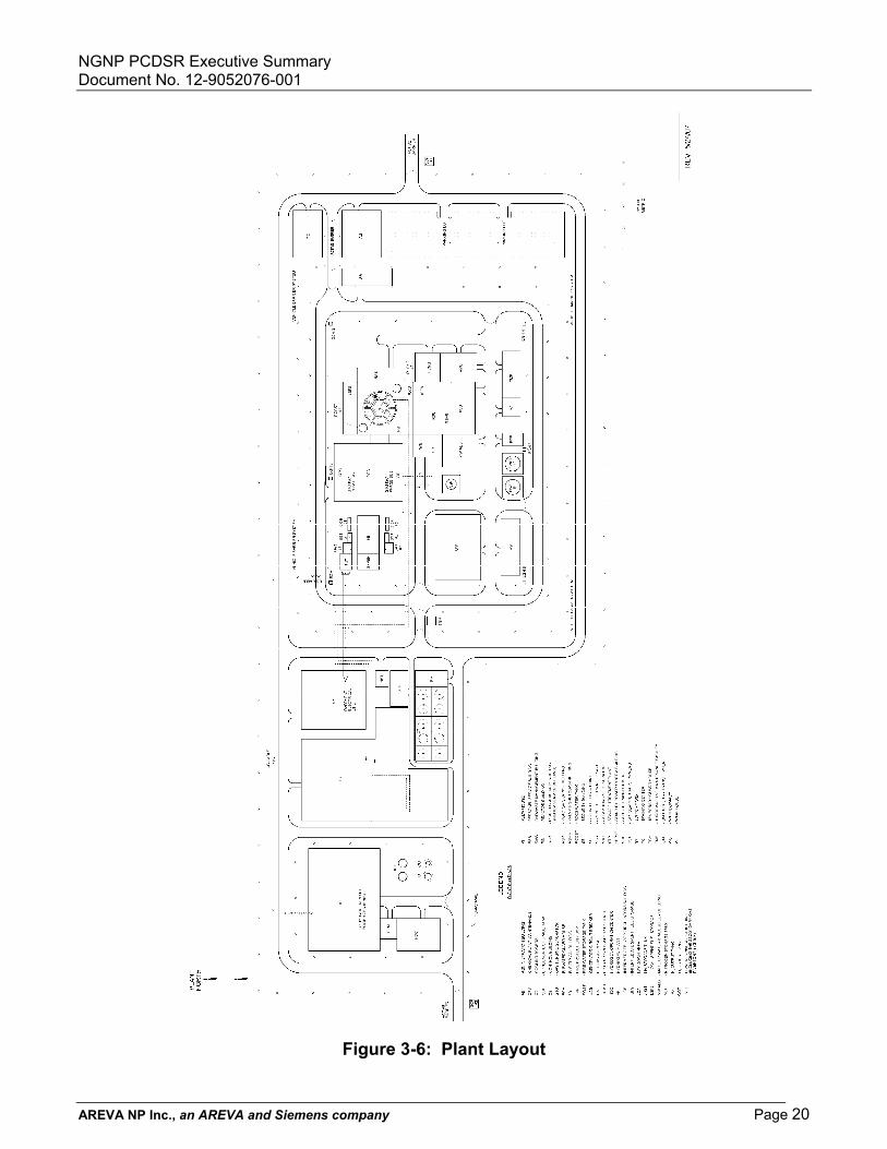
3.6 Plant Layout The Reactor and IHX vessels are located in a dedicated Reactor Building. The entire Reactor Building is located below grade, except for the associated portion which houses the Reactor Cavity Cooling System water storage

NGNP PCDSR Executive Summary Document No. 12-9052076-001
AREVA NP Inc., an AREVA and Siemens company Page 19
tanks. The Reactor Building structure provides protection against external hazards including seismic events and aircraft threats.
The Reactor Service Building is located at one end of the reactor complex. It houses the new fuel preparation and storage area and irradiated fuel storage. The Reactor Auxiliary Building houses waste processing and other necessary functions. Non-nuclear activities are housed in other adjacent buildings where the main control room is also located. Additional long-term irradiated fuel storage would be provided in a separate storage facility.
Figure 3-6 shows the overall plant layout.
NGNP PCDSR Executive Summary Document No. 12-9052076-001
AREVA NP Inc., an AREVA and Siemens company Page 20
Figure 3-6: Plant Layout

NGNP PCDSR Executive Summary Document No. 12-9052076-001
AREVA NP Inc., an AREVA and Siemens company Page 21
4.0 FUEL SUPPLY STRATEGY The NGNP fuel program will establish a domestic production facility with a robust fuel fabrication process which will be capable of reliably delivering finished fuel to the NGNP on the desired reload schedule. The processes selected, including the internal gelation process for the kernels, continuous coatings, thermosetting resins for the compacts, etc. have been demonstrated to produce high quality fuel. The fuel fabrication system will be able to be expanded as necessary, by adding modules to the production facility, as the demand for high temperature gas cooled reactors, and subsequently the need for fuel increases in the coming years.
Building on the current development and scale-up activities, the AREVA/BWXT team will be able to implement a strategy utilizing the existing BWXT pilot fuel facility while constructing and commissioning a production facility capable of meeting the reload needs of the NGNP reactor. The approach identified herein will deliver first core on time with the potential to deliver the core several years early, as well as be in a position to deliver the reload fuel on schedule.
In addition to meeting the schedule needs of the program, the strategy meets all of the objectives identified in the NGNP Preliminary Project Management Plan, namely development of a fuel system that will allow the NGNP to demonstrate all performance aspects of the plant, including economic feasibility of a fuel system capable of higher burn ups.
4.1 Fuel Strategy The TRISO fuel development, qualification, and production program must ensure the following high-level objectives of the NGNP are met:
1. Develop and implement the technologies important to achieving the functional performance and design requirements determined through close collaboration with commercial industry end-users.
2. Demonstrate the basis for commercialization of the nuclear system, the hydrogen production facility, and the power conversion concept. An essential part of the prototype operations will be demonstrating that the requisite reliability and capacity factor can be achieved over an extended period of operation.
3. Establishing the basis for licensing the commercial version of NGNP by the Nuclear Regulatory Commission. This will be achieved in major part through licensing the prototype by NRC and initiating the process for certification of the nuclear system design.
4. Fostering rebuilding of the US nuclear industrial infrastructure and contributing to making the US industry self-sufficient for our nuclear energy production needs.
For NGNP to be fully successful in achieving the identified high-level objectives, a fuel development strategy has been formulated that utilizes and expands existing commercial fuel facilities, and enables the NGNP program to meet the anticipated reactor performance requirements, which will demonstrate the basis for commercialization of the nuclear island, as well as establish the basis for licensing the reactor and fuel system by the NRC, and developing a domestic fuel supply.
Equally important to meeting these high-level objectives, the strategy developed meets the anticipated delivery requirements to support reactor startup in the 2018 timeframe, assuming the start dates are met and funding profiles identified are provided.
Fuel related requirements and key parameter values have been specified in two top-level NGNP project requirements documents, the System Requirements Manual and the NGNP Prototype Design Baseline. These documents specify that the base fuel for the NGNP will be a TRISO coated particle containing a less than 20% enriched fuel kernel. These particles will be fixed into cylindrical, graphite matrix compacts, which are, in turn, placed into hexagonal graphite blocks.
NGNP PCDSR Executive Summary Document No. 12-9052076-001
AREVA NP Inc., an AREVA and Siemens company Page 22
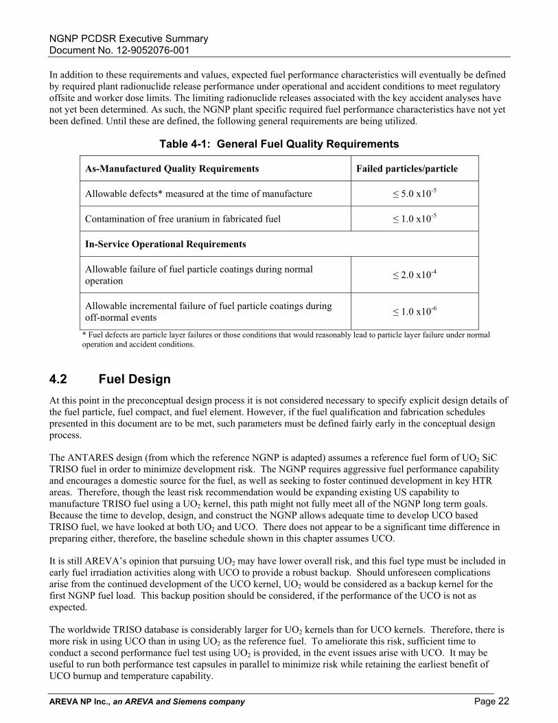
In addition to these requirements and values, expected fuel performance characteristics will eventually be defined by required plant radionuclide release performance under operational and accident conditions to meet regulatory offsite and worker dose limits. The limiting radionuclide releases associated with the key accident analyses have not yet been determined. As such, the NGNP plant specific required fuel performance characteristics have not yet been defined. Until these are defined, the following general requirements are being utilized.
Table 4-1: General Fuel Quality Requirements
As-Manufactured Quality Requirements Failed particles/particle
Allowable defects* measured at the time of manufacture � 5.0 x10⁻⁵
Contamination of free uranium in fabricated fuel � 1.0 x10⁻⁵
In-Service Operational Requirements
Allowable failure of fuel particle coatings during normal operation � 2.0 x10⁻⁴
Allowable incremental failure of fuel particle coatings during off-normal events � 1.0 x10⁻⁶
* Fuel defects are particle layer failures or those conditions that would reasonably lead to particle layer failure under normal operation and accident conditions.
4.2 Fuel Design At this point in the preconceptual design process it is not considered necessary to specify explicit design details of the fuel particle, fuel compact, and fuel element. However, if the fuel qualification and fabrication schedules presented in this document are to be met, such parameters must be defined fairly early in the conceptual design process.
The ANTARES design (from which the reference NGNP is adapted) assumes a reference fuel form of UO2 SiC TRISO fuel in order to minimize development risk. The NGNP requires aggressive fuel performance capability and encourages a domestic source for the fuel, as well as seeking to foster continued development in key HTR areas. Therefore, though the least risk recommendation would be expanding existing US capability to manufacture TRISO fuel using a UO2 kernel, this path might not fully meet all of the NGNP long term goals. Because the time to develop, design, and construct the NGNP allows adequate time to develop UCO based TRISO fuel, we have looked at both UO2 and UCO. There does not appear to be a significant time difference in preparing either, therefore, the baseline schedule shown in this chapter assumes UCO.
It is still AREVA’s opinion that pursuing UO2 may have lower overall risk, and this fuel type must be included in early fuel irradiation activities along with UCO to provide a robust backup. Should unforeseen complications arise from the continued development of the UCO kernel, UO2 would be considered as a backup kernel for the first NGNP fuel load. This backup position should be considered, if the performance of the UCO is not as expected.
The worldwide TRISO database is considerably larger for UO2 kernels than for UCO kernels. Therefore, there is more risk in using UCO than in using UO2 as the reference fuel. To ameliorate this risk, sufficient time to conduct a second performance fuel test using UO2 is provided, in the event issues arise with UCO. It may be useful to run both performance test capsules in parallel to minimize risk while retaining the earliest benefit of UCO burnup and temperature capability.

NGNP PCDSR Executive Summary Document No. 12-9052076-001
AREVA NP Inc., an AREVA and Siemens company Page 23
4.3 Fuel Qualification Plan In order to meet the fuel performance requirements that would allow reliable operation under specified NGNP operating conditions, fuel with fabricated quality and operational characteristics at least as good as past German particle fuel will be required. There are two approaches that can be considered to meet this goal. Past German fabrication processes, practices, and equipment can be replicated, to the extent possible, in the hopes of producing product with similar characteristics. Alternatively, past German experience can be examined and key fabrication concepts coupled with modern fabrication techniques. AREVA/BWXT has chosen the latter approach for its fuel qualification program. Though this approach may require a more rigorous testing and qualification program, it will allow easier extrapolation to operational conditions beyond the German experience.
The NGNP operational date of 2018 presents significant challenges to the development of a fuel qualification program. In order to meet this date and conduct the irradiation and testing necessary to support the plant safety case, the fuel qualification must be success-based. That is, the steps are defined with the assumption that each irradiation will be successful and that acceptable fuel performance will be demonstrated at each step. . In the schedule for fuel development and production provided below, there is adequate time built in for one repeated test capsule, if unexpected fuel failures are seen.
There are three fabrication-irradiation-test sequences envisioned for the fuel qualification program. In each case, coating will be done in a 6" coater to baseline conditions, and a range of certain variables to provide a range of fabrication conditions, using BWXT fabrication processes. Coated particles will be certified to a NGNP fuel specification. Compacts will be fabricated to baseline conditions in the pilot facility in Lynchburg using the AREVA compacting process. Each of the irradiation capsules used during these sequences will be monitored to detect particle failure such that appropriate actions can be taken on a timely basis.
The first test sequence is designed to provide an early indication that the fuel and testing equipment will perform as expected. A smaller quantity of fuel would be irradiated in this sequence, since no statistical inferences will be drawn from the results. It is in this sequence that consideration should be given to irradiation of some UO2 particles as backup to the UCO fuel. Should the UCO fuel fail to perform as expected, the NGNP startup date of 2018 would still be in jeopardy, but the head start provided by the presence of the UO2 would mitigate the schedule impact. All of the fuel in this sequence would be fabricated in the pilot facility.
The second sequence is designed to provide the data used to qualify the fuel for use in the NGNP plant. A quantity of fuel would be fabricated, irradiated, and inspected that would yield the statistics required to demonstrate that the fuel supports the plant safety case. This fuel would also be fabricated in the pilot line. It is envisioned that several batches would be made and blended to form a homogeneous lot upon which the results would be based. This process will be used to as closely as possible reflect anticipated commercial scale fabrication techniques. The statistical basis and acceptance criteria for the test will reflect this processing technique.
The last sequence will provide the data necessary to verify that the commercial production line is capable of reliably and repeatably producing fuel with the same performance characteristics as that produced on the pilot line. The majority of fuel for this sequence will be fabricated on the commercial production line, though some limited quantity of fuel from the pilot line may be included to provide the opportunity for direct comparisons of particle performance. The quantity of fuel contained in this sequence will be determined by the extent of difference between the pilot and production lines.
4.4 Fuel Fabrication Plan The steps required for development and qualification of UO2 fuel and UCO fuel are essentially identical. The plan discussed in this chapter mentions UCO fuel form, since questions have been raised regarding the development path for UCO. However, the steps would be the same if the selected fuel form is UO2. Similar

NGNP PCDSR Executive Summary Document No. 12-9052076-001
AREVA NP Inc., an AREVA and Siemens company Page 24
steps would be followed whether for an initial UO2 program to be subsequently complemented with UCO, for an all UCO program, or for a parallel UO2/UCO program.
Until a detailed design for the NGNP is complete, the quantity of fuel needed for the first core and reloads is not clearly defined. For this preconceptual design report, it is assumed that the initial core will contain 5000 kg of uranium in the form of TRISO coated UCO particles. In addition, it is assumed that half of the core will be reloaded every 18 months.
To support the NGNP reactor long-term and minimize capital expenditures, a fuel facility needs to be constructed that can meet the desired reload schedule. For this report, the facility output is assumed to be 2,000 kg uranium per year. This quantity meets the 2,500 kg uranium per 18 months with a 20% excess capacity to accommodate production upsets which may occur during initial commissioning of the facility.
Although several particle fuel fabrication facilities throughout the world have existing capacity to support their needs, there does not appear to be significant excess capacity to take on the additional needs of the NGNP. Therefore, the facility construction, commissioning, licensing, and qualification steps that must be undertaken for a US supplier, must also be undertaken for existing international suppliers as well.
For the NGNP to fully meet the high level objectives, the fuel fabrication facility must:
1. Demonstrate the performance of fuel fabricated in existing facilities to meet the enhanced requirements of the NGNP;
2. Qualify fuel fabrication capabilities in existing facilities;
3. Upgrade or construct a production facility capable of meeting the reload schedule of NGNP;
4. Verify fuel performance from the production line;
5. Support NRC licensing of production facility; and
6. Produce NGNP fuel by the project delivery date.
For these reasons, we believe that the preferred overall fuel supply option is to support development of a domestic fuel fabrication facility.
The existing pilot facility on the BWXT site would be used to produce the Performance Test fuel. The existing facility is licensed under the regulatory authority of the NRC and has recently successfully completed the tri-annual audit of the NQA-1 quality program.
This fuel will be tested under operating and accident conditions to demonstrate the performance characteristics of the fuel fabricated using current-technology, in near-production sized equipment, including a 6” coating furnace.
While the Performance Test fuel is being irradiated and after some burnup has accumulated, Qualification Fuel will be fabricated and pressed into compacts for qualification testing. For this qualification, several more compacts will be fabricated to ensure a statistically significant number of particles are tested to demonstrate performance and qualify the manufacturing and inspection techniques.
During the Performance Test fuel fabrication and irradiation program, the design and construction of the manufacturing facility will begin. The production facility will utilize the technology employed in the pilot facility, but scaled-up and enhanced for continuous high-volume throughput.
To meet the schedule objectives, the production facility needs to be complete, commissioned, and in production by mid-2012.
In order to be fully successful using this option, some programmatic risk must be assumed. For example, Qualification Fuel must be fabricated before the Performance Test fuel has completed its irradiation and post-

NGNP PCDSR Executive Summary Document No. 12-9052076-001
AREVA NP Inc., an AREVA and Siemens company Page 25
irradiation examination. The technical risk to the program, should this strategy be implemented, can be somewhat mitigated by the design of the irradiation test, i.e. the capsule design will permit real time in-core fuel failure monitoring which will give an indication of performance during normal operating conditions.
Another opportunity to accelerate the schedule is to design and construct the fabrication facility based on the fabrication experience gained and the preliminary in-core results of the performance test fuel. The risk to the program is judged to be very small. A significant portion of the schedule acceleration is in the design and construction of the production building itself. The overall size will be unaffected by the performance of the irradiation tests. Several of the long-lead equipment items, likewise, will be unaffected by the preliminary results of the performance test fuel. Minute processing details which could be affected by the irradiation test results have short delivery times and minimal cost. Therefore, these parts of the equipment can be made last-minute if necessary, or remade with minimal cost should the need arise.
The final opportunity to accelerate the schedule is to “qualify” the fuel fabrication process using the pilot-scaled facility, including the 6” coating furnace. Then, once the production facility is completed and commissioned, a “verification” run will be made to prove the performance of the fuel fabricated in the production facility matches the performance of the qualification fuel fabricated in the pilot facility.
Figure 4-1 shows a high-level schedule of what the fuel development/qualification/ production strategy would be. Note that the dashed lines are used to schematically represent data flows between activities and do not represent the expected timing of the data transfer.
Although this schedule meets the first core delivery milestone of 2018, a significant feature is the use of the pilot fuel facility to manufacture fuel for four years. During this time, the qualification irradiations are being performed and the production facility is being constructed.
Use of the pilot facility reduces overall risk to the program because:
� Experienced operators will maintain their skills
� Opportunities to improve the process and develop alternative procedures will be available
� Pilot facilities will be maintained, allowing the possibility to reproduce materials in pilot -scaled equipment.

NGNP PCDSR Executive Summary Document No. 12-9052076-001
AREVA NP Inc., an AREVA and Siemens company Page 26
Pilot Facility
Fabricate Verification
Fuel
Pilot Facility
Begin Production 10/2014
Equipment Install & Checkout
Irradiation & Safety Test
Fabricate Qualification
Fuel
Fabricate Performance
Fuel
Irradiation & Safety Test
Build Production Facility
Irradiation & Safety Test
Fabricate Production Fuel in Pilot Facility
2009
2010
2011
2012
2013
2014
2015
2008
Figure 4-1: NGNP Fuel Program Schedule
NGNP PCDSR Executive Summary Document No. 12-9052076-001
AREVA NP Inc., an AREVA and Siemens company Page 27
5.0 SAFETY AND LICENSING
5.1 Safety The safety of the AREVA NGNP concept relies on passive systems and inherent design characteristics that provide a high confidence that the plant safety mission is met without dependence on redundant active systems. Implementation of this safety philosophy with added adherence to the traditional concept of design defense-in-depth where execution of plant safety functions do not depend on a single system or component leads to a simplified safety case. This reliance on natural laws provides high confidence that the safety requirements are met in the event of failure of engineered systems that rely on motive power.
The high level of safety of the AREVA NGNP concept stems from the following design choices:
Ceramic Fuel Particles - The particle fuel coatings form billions of independent primary fission product barriers made from multiple ceramic materials covering the fuel kernel. These coatings individually and independently stop, contain and retain a large fraction of the fission products produced in the fuel kernel.
Graphite Core - The high heat capacity and the low power density of the graphite annular core results in very slow and predictable temperature transients. In addition, the strength of graphite increases with temperature up to levels well above those associated with licensing basis events. Adequate passive core heat removal is achieved under both pressurized and depressurized primary system conditions.
Helium Coolant - The use of an inert, single phase gaseous coolant eliminates the possibility of a complete loss of coolant event. Pump/circulator cavitations can not occur, and no chemical reaction between the coolant and graphite, or fuel is possible. Furthermore, adequate active core heat removal can be achieved under either pressurized or depressurized primary system conditions.
Negative Reactivity Feedback – Reactor core design retains an inherent negative reactivity feedback characteristic. If core temperatures increase, power level decreases. This property ensures that fuel temperature rise is self-limited for loss of heat removal events.
Core Region Structural Configuration – The annular geometry of the core, the low power density, and the high thermal capacity ensure the cooldown of the shutdown reactor under emergency conditions by passive removal of heat from the reactor vessel using heat emission, conduction, and convection. As a result, fuel and core temperatures remain within allowable limits in all relevant accident scenarios.
In addition to the above inherent design features, the AREVA NGNP concept has multiple reactor trip mechanisms and decay and residual heat removal systems, including the normal shutdown system, the reserve shutdown system, the secondary nitrogen/helium loop in conjunction with the primary heat transport loop, the SDHRS, the reactor SCS, and the RCCS. The combination of inherent safety characteristics and the engineered plant protective features result in peak post-accident fuel temperatures that fall well below the range of fuel temperatures that would cause significant fuel damage leading to release of fission products.
Furthermore, a key inherent characteristic of the AREVA NGNP concept plant is its slow response which, combined with passive residual heat removal, simplifies the operator's role and provides long time intervals for deliberate actions, thus minimizing the opportunity for operator error.
As a result of these safety features, the AREVA NGNP plant is highly resistant to significant plant damage, even after design basis events, such that the owner’s investment is continuously protected and a high degree of public safety is achieved without the reliance on off-site emergency management measures.
NGNP PCDSR Executive Summary Document No. 12-9052076-001
AREVA NP Inc., an AREVA and Siemens company Page 28
5.2 Licensing The NGNP must be licensed by the NRC in accordance with the requirements of 10 CFR Part 50 or 10 CFR Part 52. NRC licensure is a key requirement specified for the NGNP to support successful future plant commercialization. Furthermore, as a first-of-a-kind (FOAK) non-light-water reactor licensed as a demonstration plant for both electricity production and hydrogen generation, the NGNP provides the required regulatory technical basis that will serve the future commercialization of similarly designed plants.
5.2.1 Prototype Licensing Experience from the operation and prototype testing of the demonstration NGNP will be needed to support the design certification of future commercial versions. Therefore, the NGNP as the FOAK prototype will be licensed under the conventional two step 10CFR50 licensing process:
1. Secure a construction permit based on the review of a preliminary safety analysis report (PSAR); and,
2. Secure an operating license based on the review of a final safety analysis report (FSAR). The license will initially be for a non-LWR "prototype" plant that will be converted to a commercial Class 103 license following a successful demonstration period.
Additionally, AREVA recommends that elements of 10 CFR 52 be carried out in parallel with the Part 50 licensing process, in particular, maintaining close liaison with the NRC through pre-application technical exchanges and interactions that will be necessary to develop technology neutral licensing framework and HTR technology specific licensing bases for the NGNP demonstration facility license leading to development of regulatory bases for commercial plants of similar design.
The proposed hybrid approach satisfies the need to initiate construction activities as early as possible but also minimizes the risk of construction prior to obtaining an operating license. However, the opportunity that the Part 50 approach offers in terms of an early construction start can only be seized if the key licensing issues such as containment versus confinement can be resolved early in the licensing process and later demonstrated by plant performance tests.
5.2.2 Commercial Plant Licensing It is essential that NGNP licensing process and the risk-informed performance-based licensing initiative be closely coupled to ensure the successful transition from NGNP licensing to the commercial licensing framework. This initiative is expected to result in the codification of the proposed risk-informed and performance-based alternative to Part 50 regulations.
Once the commercial licensing framework is in place, reactor vendors can seek design certification (DC) from the NRC for their designs and plant owners can seek a combined construction-operation license under a one-step process (i.e., 10 CFR 50.52 or equivalent).
5.2.3 Regulatory Requirements Development The development of the regulatory framework (i.e., requirements and process) for the licensing of future commercial non-LWR nuclear power plants has been outlined by the NRC staff in draft NUREG-1860. The purpose of this framework is to provide the technical basis to support the development of a technology-neutral, risk-informed and performance-based process for the licensing of new nuclear power plants (NPP).
This framework approach, scope and criteria may eventually be used by the NRC staff to develop a set of regulations that would serve as an alternative to 10 CFR 50 for licensing future nuclear power plants. The regulations developed from the framework approach could still be used in conjunction with 10 CFR 52 for carrying out the licensing process, i.e., obtaining a combined operating license and/or design certification. The NGNP licensing process proposed by AREVA team can be used to exercise the framework and develop the technical bases that will be needed for the new regulation.

NGNP PCDSR Executive Summary Document No. 12-9052076-001
AREVA NP Inc., an AREVA and Siemens company Page 29
6.0 PLANNING FOR COMPLETION OF NGNP PROJECT As discussed previously the preconceptual design scope of work performed by the AREVA team was limited to the nuclear heat source, and the power conversion system for the electric generating plant. Therefore, the depth and level of detail of the associated with the plant cost estimate and project schedule is commensurate with the AREVA scope of work and the project design status, i.e. pre-conceptual design stage.
6.1 Cost and Economics The NGNP cost estimate was prepared in accordance with the BEA latest work Breakdown Structure (WBS) provided to AREVA. The WBS covers the entire lifecycle of the NGNP prototype facility beginning with the Design and terminating after several years of DD&D phase.
At INL’s request, the cost estimate and economic analysis is not included in this summary report. This information is being submitted to INL/BEA separately.
6.2 Project Schedule The NGNP project schedule encompasses the total time span beginning with the project conceptual design phase, concurrent supporting research and development activities identified in this report, licensing and permitting activities necessary to obtain an operating license, plant construction activities, long-lead component procurement including steps to be taken for key hardware acquisition, plant commissioning, testing and initial operation, leading to commercial plant demonstration and operations. Although not shown or detailed, the project schedule includes the 38 years of the NHS and PCS commercial operation and a final six year period of decommissioning, decontamination, and dismantling/disposition (DD&D). The NGNP high level project schedule is shown in Figure 6-1. A more detailed project schedule is provided separately
Key elements of the AREVA NGNP project schedule consist of:
� Plant Design
� Research and Development
� Licensing and Permitting
� Procurement
� Construction
� Initial Startup and Commissioning
� Commercial Operations
� Decommissioning
The NGNP plant design will be completed in three successive phases of conceptual, preliminary and final design. The six year phased approach to plant design although aggressive is considered achievable. The plant design is followed up by six years of plant construction that begins after an LWA is received from the NRC for the silo excavation.

NGNP PCDSR Executive Summary Document No. 12-9052076-001
AREVA NP Inc., an AREVA and Siemens company Page 30
8 9 10 11 12 13 14 15 16 17 18 19 20 21 59 60 61 62 63 64
Design -- CD-- PD
-- FD
R&D
Licensing - LWA and CPLicensing - OL
OLConstruction
LWACP Test and Initial Ops
Commercial OpsProcurement
Fuel DD&DVessel
IHXGraphite
Figure 6-1: NGNP High Level Schedule
The traditional start of the nuclear plant construction (first pour of concrete) is after the NRC grants a construction permit in accordance with regulations of 10 CFR Part 50. The total construction phase lasts six years and includes on site final assembly of the reactor vessel. This deemed necessary due to location of the Idaho site and access and size limitations for large component transportation.
Concurrent with the design and construction of the NGNP two important elements of the schedule must also come to successful conclusions. The first element is licensing and permitting. The Nuclear regulatory commission must review the design of the NGNP and grant an operating license. This is accomplished through many reviews and independent safety analyses by the regulator. The licensing path being recommended by AREVA is a combination of demonstration plant test (104c) and commercial plant (103) class license application. This path will be discussed with the NRC staff and agreed on at the start of pre-application interactions. The necessary regulations for licensing the nuclear plant technology used by the NGNP (modular high temperature gas cooled and graphite moderated reactor) does not exist, therefore, ample time is allocated for extensive review and safety assessment of this technology.
The second of the key elements of the NGNP prototype facility schedule is the development and procurement of long-lead components. The NGNP prototype facility is scheduled for initial plant startup and criticality in 2018. This requirement will drive the design choices and long lead acquisition of major components especially the following long term items:
Fuel – The R&D necessary for fuel acquisition and the design of the commercial fuel plant must begin concurrent with the conceptual design phase of the reactor plant in order to produce qualified fuel and perform qualification irradiation and safety design bases of the coated particle fuel and manufacture the initial core by 2018 plant startup and maintain an infrastructure for subsequent fuel supply for the NGNP prototype facility.
Reactor Vessel – the material used for the NGNP reactor vessel is Modified 9Cr-1Mo which requires ASME codification and manufacturing process development. The large size of the NGNP vessel demands large forging. World metal forging capacity and suppliers are quite limited and the upsurge in the nuclear renaissance demand early action for acquisition of forging material to meet the 2018 reactor
NGNP PCDSR Executive Summary Document No. 12-9052076-001
AREVA NP Inc., an AREVA and Siemens company Page 31
startup date. AREVA estimates that an order for the vessel forgings must be placed in 2008 in order to meet the 2018 startup date. It is proposed to base the design of the reactor vessel on a combination of plates and forgings in order to minimize costs and risks by reducing the number of large forgings required.
IHX – Another important element of the NGNP facility is the intermediate heat exchanger that must be designed, procured, and built in time for the 2018 plant startup. This drives the choices of the IHX and the plant heat transport system configuration. A compact heat exchanger He-to-He IHX was selected for the heat transport loop to the hydrogen production plant. The multi-loop design of the AREVA NGNP offers a test bed for experimentation and demonstration of a variety of advanced IHX designs throughout the life of the NGNP plant including the yet to be developed ceramic IHX. A fundamental objective of the NGNP is the commercial demonstration of the electric plant and for this part of the NGNP heat transport three robust shell and tube heat exchangers have been recommended. The design and manufacturing of the tubular IHX is considered near critical path.
Graphite – Extensive use of graphite throughout the NGNP design and lack of current experience with the supply of nuclear grade graphite will require an aggressive R&D and acquisition strategy to ensure qualification data is available and that a supply of nuclear grade graphite is available for fuel, reflector, and core support manufacturing and delivery in time for the 2018 plant startup. The on-going international qualification effort must be supported and accelerated to meet the NGNP design and delivery requirements.
Other Components - the gas circulators, hot gas duct, and isolation valves are NGNP components that require special attention to be paid to their design, testing, and procurement. Although these components are not considered on critical path, they are close to critical path. Therefore, special attention must be paid to the schedule of these procurements to ensure they remain off the critical path.

NGNP PCDSR Executive Summary Document No. 12-9052076-001
AREVA NP Inc., an AREVA and Siemens company Page 32
7.0 RISK MANAGEMENT AND R&D Risk management is a continuous process that identifies, analyzes, prioritizes, mitigates and tracks risks associated with a project. The scope of risk management applies to all phases of the NGNP project: design, construction, start-up, and operation.
Research and development is closely related to the risk management process. Successful development of the NGNP will depend to a large extent on the research done to address the technical risks identified in the risk management process. Additionally, the relationship between risk management and R&D is an iterative one. An identified risk may be mitigated by focused R&D aimed at resolving the risk whereas R&D, by its very nature, will explore the limits of current knowledge and experience and in turn identify additional risk. Also, it must be recognized that R&D may only resolve technical issues and that risk management also includes non-technical risks (e.g., social, political, financial etc.).
The AREVA NGNP team identified NGNP project risks and prioritized them by use of a standard probability/consequence of occurrence ranking technique. Similarly, the AREVA NGNP team has borrowed from the aerospace industry the technology readiness level (TRL) ranking technique and coupled it with the phenomenon importance ranking technique (PIRT) technique to identify R&D needs. The results are summarized in the following sections.
7.1 Project Risk Management
7.1.1 Key Risks In applying the Risk Management approach described above, five areas emerge as presenting the greatest risk to the NGNP project. These “key” risk areas are discussed below. These areas have the highest unmitigated probability/consequence (P/C) scores, and as such, need to be targeted for immediate action and monitoring by management.
� Fuel Development and Performance
With respect to fuel, risks items include insufficient funding to allow a full fuel qualification program (D-005), unavailability of required test reactors (D-006), overall fuel performance during irradiation and safety testing (D-007), and fuel coating challenges (D-009). In the case of fuel performance, the probability of the risk can be reduced, but the potential consequence cannot be significantly minimized. Collective mitigation strategies include: o Initiate and fully fund the fuel development and qualification effort in the near future. o Identify fuel irradiation and inspection needs immediately and reserve required resources. o Fuels team is set up to consider a wide range of fuel variables that should result in an acceptable
qualification effort. o Develop fuel fabrication process based on the use of multiple, proven coaters.
� Nitriding of Materials
Nitriding of materials (Risk D-001) is a risk because of the high nitrogen content of the secondary gas. This could affect the IHXs serving the PCS and some PCS components. Steps that will be taken to mitigate this risk include the following:
o Tests will be performed to determine severity of the nitriding effect.
o Based on the test results, nitriding protection methods or use of alternate secondary gas may be employed.
NGNP PCDSR Executive Summary Document No. 12-9052076-001
AREVA NP Inc., an AREVA and Siemens company Page 33
� Heavy Component Procurement and Fabrication
With respect to procurement and fabrication of large forgings of Mod 9 Cr 1 Mo for the reactor vessel, industrial capacity is limited in forging size and experience such that the delivery timeframe of the forgings may not be compatible with the NGNP schedule (Risk P-002). For other, more standard large components (e.g., gas and steam turbines), feasibility is not an issue but timely procurement is because of the lengthy procurement lead times (4-5 years) arising from the world-wide demand for these components (Risk P-001). To mitigate these risks, the following actions can be taken:
o Book large forgings and casting material at the basic design stage. Engage the potential primary supplier for Mod 9 Cr 1 Mo forgings early in the conceptual design process assess feasibility and schedule issues.
o Ensure commitments for the procurement of standard large components are placed on a schedule compatible with 2018 NGNP startup.
� Licensing
In the area of licensing, one key risk is the NRC may find the radionuclide containment approach unacceptable (L-001). This risk is also tied to fuel performance goals. Mitigation strategies here include:
o Close interaction with the NRC on this issue. o Ensure fuel performance goals are met so that a hard containment is unnecessary.
� Project Funding Project funding also affects many other risk and programmatic areas. Consistent funding is required for R&D, design, procurement, and construction in order to achieve the NGNP mission. To mitigate this risk:
Closely monitor funding through the DOE – may need to rework schedule and/or scope to accommodate revised funding scenarios
7.2 Research and Development Needs Although the VHTR is an unprecedented first of a kind (FOAK) system, the basic technology for the next generation nuclear plant (NGNP) has been established in former high temperature gas-cooled reactor plants and in current day research scale projects such as the Japanese HTTR and Chinese HTR-10 which are scaled reactors demonstrating the feasibility of some of the planned NGNP technology and materials. Nevertheless, additional research and development (R&D) is needed to increase coolant temperature beyond 850 ºC core outlet temperature and to develop the interface between the Nuclear Heat Source (NHS) and the heat utilization systems.
7.2.1 Approach to Define R&D Needs The general approach AREVA took to define applicable R&D needs for the NGNP is as follows:
First, the objectives and scope of VHTR hardware and analytical computer codes were determined from the work breakdown structure (WBS). Next, subject matter experts were surveyed to determine current technology maturity, R&D needs to mitigate technical risk and/or resolve critical issues, prioritize R&D needs, estimate cost and schedule, and identify facilities to perform the R&D. An adaptation of the aerospace Technology Readiness Level (TRL) approach was used to define technological maturity. The “Importance” and “Knowledge” parameters of the Phenomena Identification and Ranking Technique (PIRT) were used to prioritize R&D needs. The surveys were then compiled, compared to previous applicable VHTR work, and iterated for completeness and consistency. The risks and risk mitigation approaches identified in the risk management process were then used to confirm that all R&D needs have been identified.

NGNP PCDSR Executive Summary Document No. 12-9052076-001
AREVA NP Inc., an AREVA and Siemens company Page 34
7.2.2 R&D Needs Application of the approach described above resulted in the identification of the following R&D needs that are crucial to the success of the project:
� Fuel development and qualification, particularly irradiation and testing of compacts and mass production processes. R&D costs in this area are about $207 million.
� Materials development and qualification. This covers certain high-temperature steels, composites, and graphite selection/qualification. The associated R&D costs are estimated at $33 million.
� Components testing. A large (10 MW) helium test loop is required for prototype tests of components. This loop could cost as much as $110 million. An additional $50 million would be needed for actual hardware tests (includes a smaller 1 MW test facility).
� Computer codes & methods development/qualification. Included here are neutronics, fuel performance, heat transfer, and mechanical analysis codes. The total R&D expense is estimated at over $26 million with $8 million associated with neutronics code benchmarking to critical experiment data.
� Power Conversion System. This covers nitriding tests and future improvement of compressor blade performance. The associated R&D costs are estimated at $10 million.
In total, the R&D program is expected to cost about $440 million and span 60 months
7.3 Overall Risk/R&D Implications Without a doubt, the risk represented by fuel development impacts the potential success of the NGNP project in many areas.
First and foremost at risk is the validation of the safety case for the NGNP. Without superior fuel performance, the safety case is severely jeopardized and the licensing strategy becomes void. The implication is a costlier plant due to the requirement for a hard containment plus an emergency planning zone that expands well beyond the site boundary, necessitating complicated and costly emergency planning measures. This seriously affects locating the commercial plant near population centers.
Second, there is the attendant schedule risk. The fuel development, qualification, and fabrication activities comprise the project’s critical path and there is not sufficient contingency to accommodate any setbacks in the process. Should any of the fuel irradiations produce bad results, it will be difficult to maintain a schedule that meets the 2018 startup target.
Other risk areas are manageable to a much higher degree. In the heavy components area, the nuclear resurgence is spurring growth in the industry such that manufactures are expanding existing facilities or are considering opening new facilities or revitalizing old ones.
There is no clear fall back position with regards fuel performance that is palatable with respect to schedule or redeeming with respect to plant economics. It is possible that the NGNP design or operating strategy could be adjusted such that much less demand is placed on the fuel resulting in a more favorable or acceptable operating regime relative to fuel performance. However, this implicitly assumes that a minimum level of acceptable fuel performance commensurate with past German fuel experience can be obtained.
Ultimately, the overall project risk considers the ability to achieve the top-level project objectives. In the simplest terms, the overall NGNP project risk can be summarized in three key elements:

NGNP PCDSR Executive Summary Document No. 12-9052076-001
AREVA NP Inc., an AREVA and Siemens company Page 35
� Project fails to be completed
� Prototype never meets performance objectives
� Project fails to support commercialization objectives
The overall technical and cost risks are judged to be moderate. However, the overall schedule risk is judged to be significant due to external programmatic factors. These risks are judged to be manageable, if prompt aggressive action is taken in key areas.
The overall project risk is still significant due to external programmatic factors. In terms of the three elements of overall risk to project objectives defined above, the risk is summarized as
� Risk to project completion is high. This is due primarily to uncertainty regarding project funding sustainability. It is also affected by lack of clear end-user support. Licensing risk is also beyond the direct control of the project organization. Efforts are underway to mitigate this risk via the Public/Private Partnership and other channels. Success in these areas will significantly reduce this risk.
� Risk to meeting project performance objectives is moderate. This risk is controlled by the overall project technical risk. Adequate execution of the required R&D plan is required to mitigate this risk.
� Risk to subsequent commercialization is moderate. There must be a clear alignment between the project and near-term markets. Steps must also be taken to bridge the perceived gap between potential end user time horizons and the anticipated FOAK commercial plant schedule.
Control of overall NGNP project risk requires prompt project execution, the development of a technology roadmap with off-ramps for key technology risks, a strategy to avoid funding and resource constraints, and alignment with commercial market needs. Adequate steps exist to reduce or mitigate the project risk. Nonetheless, the remaining risk is significant, and alternate paths such as the steam cycle might better reduce overall risk to an acceptable level.

NGNP PCDSR Executive Summary Document No. 12-9052076-001
AREVA NP Inc., an AREVA and Siemens company Page 36
8.0 NEXT STEPS Once the results of the NGNP Preconceptual Design Engineering Studies have been evaluated, a reference concept can be established as the starting point for Conceptual Design. During Conceptual Design this concept will be more fully developed and evaluated. The resulting mature design will then be detailed during the remaining design phases in preparation for fabrication and construction.
The AREVA NGNP team has identified several additional studies that would be very beneficial prior to the formal initiation of Conceptual Design. These studies include both new work completely outside the current NGNP preconceptual design effort as well as the extension of important existing work. These future studies should be given high priority early in the next phase of the NGNP program, whether that is at the initiation of Conceptual Design or an extension of the current Preconceptual Design Studies phase.
The recommended studies vary significantly in both magnitude and importance. Some are fundamental to the basic concept definition of the NGNP. It is important that those studies be resolved at the very beginning of conceptual design phase. Others are precursors or complementary to the normal engineering design activities of Conceptual Design and subsequent phases. Those studies should be addressed during the Conceptual Design phase. The remaining future studies would likely not directly impact NGNP, but they could have significant potential benefit for future plants beyond the NGNP. The suggested future studies are listed in Table 8-1.
The critical studies which have the potential to modify the basic configuration of the NGNP and which should therefore be resolved prior to the start of major conceptual design work include the following:
� Steam Cycle Concept Evaluation
� Water Ingress White Paper
� Demonstration Plant Size Confirmation
� H2 Process Selection
� In-Depth Analysis of MTE H2 Process
Special attention is directed to the recommended elements of the proposed Steam Cycle Concept Evaluation. This evaluation is fundamental, since it has the potential to completely redefine the NGNP concept. AREVA believes very strongly that the steam cycle concept should be considered as a probable replacement for the current very high temperature NGNP approach. The steam cycle concept is judged to be the most likely concept capable of leading to large scale commercial deployment in the foreseeable future. It requires less R&D and it has less technical and schedule risk compared to other concepts. Finally, it has much greater market flexibility.
AREVA strongly recommends that a thorough evaluation of the steam cycle concept’s capability to fulfill the NGNP mission objectives be performed prior to the start of full Conceptual Design.
The Steam Cycle Concept Evaluation Study and the Demonstration Plant Size Confirmation Study are noteworthy, since, of all the studies, they arguably have the largest potential impact on the NGNP concept to be selected for the initiation of Conceptual Design. These two studies are discussed in the following two sections.
8.1 Steam Cycle Concept Evaluation A steam cycle HTR concept provides an attractive alternative to other concepts such as the direct or indirect Brayton cycle or the combined cycle gas turbine (CCGT). In the steam cycle concept, the reactor outlet helium supplies heat directly to a steam generator which produces high temperature, high pressure steam. Modern steam systems can achieve electricity generating efficiencies comparable to those of Brayton cycles (40-48%) but with less demanding reactor operating conditions.

NGNP PCDSR Executive Summary Document No. 12-9052076-001
AREVA NP Inc., an AREVA and Siemens company Page 37
Perhaps more importantly, high temperature steam is directly applicable to many process heat markets, and it is relatively easy to deliver. High temperature steam (~550°C) can be transported over longer distances compared to very high temperature gas. This temperature range encompasses the majority of potential process heat markets. For very high temperature applications, a variety of means exist to augment the steam heat with supplemental electrical heating. While this imposes the inefficiency of the electricity generating process on part of the delivered energy, it minimizes the pumping and heat losses associated with very high temperature heat delivery. It also provides greater flexibility in the design of the chemical plant or other process heat facility. For example, scoping analyses of high temperature hydrogen production processes supplied with steam and electricity suggest that the actual impact on overall performance is small compared to a facility supplied directly with very high temperature heat.
A major advantage of steam cycle systems is that they can be ready to meet these energy needs in a shorter time frame with less R&D and less technical risk than higher temperature systems. Steam cycle systems require reactor outlet temperature on the order of 750°C compared to a reactor outlet temperature in the range of 850-950°C for high performance Brayton systems or very high temperature heat delivery systems. They also avoid the need for very high temperature heat exchangers or for advanced helium turbomachinery. The resulting reduction in development reduces the project schedule risk to a reasonable level.
In summary, the major potential advantages of the steam cycle concept include:
� Greater reliance on existing technology
� Reduced risk (technical, schedule, and cost)
� Shorter development and deployment schedule
� Less demanding performance for reactor and associated systems
� Comparable electricity generating efficiency to more advanced concepts
� Broad applicability to a variety of process heat markets
� Greater commercialization potential (market flexibility and earlier deployment)
AREVA strongly recommends that the steam cycle concept be strongly considered as an alternative to the higher risk reference NGNP approach. The following four activities are proposed in order to better define the characteristics of a steam cycle NGNP configuration and to characterize its relative advantage compared to the reference concept.
� Develop alternate NGNP Preconceptual Design employing steam cycle instead of high temperature IHX or direct Brayton.
� Evaluate adaptability of a separate high temperature test loop to the basic steam cycle configuration (in parallel with the steam generator in order to allow testing of high temperature components).
� Define required R&D for the steam cycle concept relative to the R&D required for the reference (~900°C) NGNP concept.
� Define project schedule for steam cycle concept relative to the reference NGNP concept.
8.2 Demonstration Plant Size Confirmation The NGNP Power Level Special Study concluded that the NGNP should be built at the full commercial size in order to maximize the benefit of the project in support of subsequent HTR commercialization. Building the NGNP at full size minimizes the technical risk, design cost, and licensing risk and effort for the future commercial plant.
NGNP PCDSR Executive Summary Document No. 12-9052076-001
AREVA NP Inc., an AREVA and Siemens company Page 38
However, while building the NGNP at full size minimizes these risk elements, it does not completely eliminate them. The actual level of minimization of risk and residual FOAK design cost for the first commercial plant that the NGNP project will provide is dependent on the similarity between the commercial plant and the NGNP prototype.
Moreover, placing the entire risk burden on the NGNP FOAK plant with the resulting impact on design and construction costs may actually maximize the risk of funding discontinuity for the NGNP, if the total project cost is a significant determinant of this risk. This consideration was not part of the existing plant power level study.
Since the completion of the Prototype Power Level Study, it has been recognized that previous assumptions regarding the relationships between prototype capital cost, design cost, plant size, and NGNP and commercial plant design differences should be refined. This is particularly true in light of the recommendation to refocus future efforts on the steam cycle concept.
Therefore, AREVA suggests a further effort with the two objectives
(1) Confirm the conclusion of the initial power level study and
(2) Explore approaches to minimize the residual FOAK design costs and risks that might affect the first subsequent commercial plant.
This follow-on study should take into account FOAK vs. NOAK development costs, fabrication costs, and risks, and the partitioning of these between the initial demonstration plant and subsequent first commercial plant. Reevaluate major breakpoints based on component transportability, capital cost (overall, number of loops, etc.), technology demonstration, etc.
It is anticipated that the conclusions of the power level study will not change substantially. Nonetheless, it would be prudent to reconfirm the study results, and it is important to identify clear strategies to minimize the residual risk and FOAK development cost in the first commercial plant.
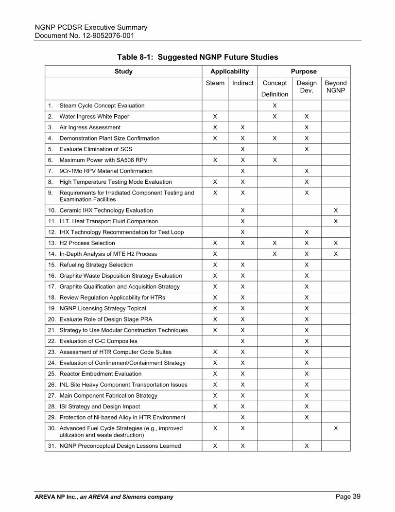
NGNP PCDSR Executive Summary Document No. 12-9052076-001
AREVA NP Inc., an AREVA and Siemens company Page 39
Table 8-1: Suggested NGNP Future Studies
Study Applicability Purpose
Steam Indirect Concept
Definition
Design Dev.
BeyondNGNP
1. Steam Cycle Concept Evaluation X
2. Water Ingress White Paper X X X
3. Air Ingress Assessment X X X
4. Demonstration Plant Size Confirmation X X X X
5. Evaluate Elimination of SCS X X
6. Maximum Power with SA508 RPV X X X
7. 9Cr-1Mo RPV Material Confirmation X X
8. High Temperature Testing Mode Evaluation X X X
9. Requirements for Irradiated Component Testing and Examination Facilities
X X X
10. Ceramic IHX Technology Evaluation X X
11. H.T. Heat Transport Fluid Comparison X X
12. IHX Technology Recommendation for Test Loop X X
13. H2 Process Selection X X X X X
14. In-Depth Analysis of MTE H2 Process X X X X
15. Refueling Strategy Selection X X X
16. Graphite Waste Disposition Strategy Evaluation X X X
17. Graphite Qualification and Acquisition Strategy X X X
18. Review Regulation Applicability for HTRs X X X
19. NGNP Licensing Strategy Topical X X X
20. Evaluate Role of Design Stage PRA X X X
21. Strategy to Use Modular Construction Techniques X X X
22. Evaluation of C-C Composites X X
23. Assessment of HTR Computer Code Suites X X X
24. Evaluation of Confinement/Containment Strategy X X X
25. Reactor Embedment Evaluation X X X
26. INL Site Heavy Component Transportation Issues X X X
27. Main Component Fabrication Strategy X X X
28. ISI Strategy and Design Impact X X X
29. Protection of Ni-based Alloy in HTR Environment X X
30. Advanced Fuel Cycle Strategies (e.g., improved utilization and waste destruction)
X X X
31. NGNP Preconceptual Design Lessons Learned X X X

NGNP PCDSR Executive Summary Document No. 12-9052076-001
AREVA NP Inc., an AREVA and Siemens company Page 40
9.0 CONCLUSIONS/RECOMMENDATIONSThis section captures the main conclusions of AREVA’s NGNP preconceptual design studies.
9.1 Special Study Conclusions The AREVA NGNP team was asked to perform four of the special studies identified in the original INL/BEA Scope of Work.
Reactor Type Comparison Study – The AREVA study concluded that the prismatic block HTR was the preferred option in order to maximize the unit power level for best economic performance.
Prototype Power Level Study – The AREVA study tentatively concluded that the NGNP prototype should be full size (565 MWth) in order to maximize the benefit to future commercial plants. This study also concluded that 60 MWth should be provided to the test loop supporting the hydrogen process demonstration facility.
Power Conversion System Study – The AREVA study concluded that a steam cycle system was preferred for near-term deployment. The study also concluded that supercritical CO2 systems may have significant potential advantages and should continue to be pursued for long-term deployment.
Primary and Secondary Cycle Concept Study – The AREVA study concluded that the reference NGNP should have reactor inlet/outlet temperatures of 500°C /900°C as the best compromise between hydrogen production performance and NHS feasibility. The study also concluded that a multiple loop primary circuit configuration using robust tubular IHXs for the main energy transfer to the PCS should be used to maximize feasibility and minimize risk.
9.2 Design Adaptation Conclusions The AREVA NGNP preconceptual design work scope required that AREVA develop an NGNP design concept adapted directly from AREVA’s existing ANTARES HTR concept employing an indirect cycle combined cycle gas turbine (CCGT) energy utilization system. AREVA’s scope did not include either the hydrogen production facility or the high temperature heat transport loop.
Therefore, the adapted NGNP design retains this configuration.
The resulting reference NGNP design is a 565 MWth prismatic HTR with a modified 9Cr-1Mo reactor vessel. Heat is supplied to three parallel loops each with a helical coil tubular IHX and a dedicated primary circulator. Tubular IHXs are used to maximize design feasibility and component lifetime for very high temperature service.
The secondary coolant from the three IHXs is combined to drive a single closed loop gas turbine. The secondary coolant is a mixture of nitrogen and helium selected to allow the use of air-breathing gas turbine technology. Residual heat from the turbine outlet drives the Rankine bottoming cycle through a heat recovery steam generator.
A fourth primary loop is included to provide heat for demonstration of high temperature hydrogen processes. Given the smaller size of this loop and the use of helium as the secondary fluid in the heat transfer loop, a compact heat exchanger is specified for this loop in order to demonstrate that new technology.
The resulting configuration is the best configuration that can be achieved in the near-term for direct high temperature heat supply. It minimizes technical risk to the maximum extent possible.
However, AREVA does not actually recommend this configuration at this temperature unless direct high temperature heat supply is the sole objective regardless of the technical challenges. As concluded in AREVA’s

NGNP PCDSR Executive Summary Document No. 12-9052076-001
AREVA NP Inc., an AREVA and Siemens company Page 41
PCS study and further recommended in the future studies section of this report, a simple steam cycle concept is the preferred configuration based on increased market flexibility, minimized technical risk, and most rapid deployment schedule.
9.3 Hydrogen Production Conclusions While the design of the hydrogen production plant was not part of the AREVA team’s assigned scope, the AREVA team did agree to perform an evaluation of high temperature steam electrolysis. This evaluation focused on overall system performance assuming heat was supplied using extraction steam from an adjacent steam cycle HTR and electric energy. Over a range of electrolyzer operating temperature of 600°C to 800°C, the best system performance was predicted at 600°C. This result is based on the overall system performance, not just the electrolyzer. Alternate electrolyzer materials would probably be needed at this lower operating temperature.
9.4 Risk and R&D Conclusions The key risks identified for the NGNP project are
� Fuel performance (the probability of this risk can be reduced, but the potential consequence can not be minimized)
� Heavy component procurement and fabrication (industrial capacity is limited both in forging size and supply schedule in the current market)
� Nitriding of secondary circuit components (assuming a nitrogen-helium mixture is used for the PCS secondary coolant)
� Licensing
� Funding continuity (consistent effort is required for R&D, design, and procurement/construction in order to achieve the NGNP mission)
The key R&D needs identified for the NGNP project are
� Fuel manufacturing and qualification
� Graphite qualification
� Modified 9Cr-1Mo qualification and codification
� High temperature materials
� Methods qualification
The overall technical, schedule, and cost risks are judged to be manageable. The challenges are significant, but they can be adequately mitigated, if prompt aggressive action is taken in key areas. Control of overall NGNP project risk requires prompt project execution, the development of a technology roadmap with off-ramps for key technology risks, a strategy to avoid funding and resource constraints, and alignment with commercial market needs.
9.5 Cost and Economic Conclusions Costs were estimated for the First-of-a-Kind reference NGNP prototype, including R&D, design, capital, operation, and decommissioning.
An economic analysis was also performed to estimate the output product cost for the commercial Nth-of-a-Kind VHTR plant. The resulting product cost and plant profitability is very sensitive to assumed escalation rates.

NGNP PCDSR Executive Summary Document No. 12-9052076-001
AREVA NP Inc., an AREVA and Siemens company Page 42
While the AREVA team did not assess the cost or economic performance of a comparable steam cycle NGNP alternative, it is clear that both the development cost and the capital cost of the steam cycle would be significantly lower than for the reference concept (probably 20-30%), while the reduction in electricity or hydrogen production efficiency would be relatively minor.
9.6 Recommended Future Studies A number of future studies have been identified as being important in determining the future direction of the NGNP project, as being necessary to support anticipated conceptual design activities, or as being beneficial to the long-term deployment of future HTRs.
Two key studies are important in determining the future direction of the program. The first is a thorough evaluation of the steam cycle as an alternative path to fulfill the NGNP mission on the desired near-term schedule with greater probability of success and greater potential for near-term commercialization. The second key study is related to confirmation of the recommended size of the NGNP prototype plant considering the partitioning of design cost, R&D, and risk between the prototype and the first commercial plant.
9.7 Overall Conclusion AREVA believes that the HTR has the potential to make a major impact on the broader energy market, if the necessary technology hurdles can be surmounted.
The AREVA reference NGNP concept using multiple tubular IHXs is the best approach, if the direct delivery of nuclear high temperature heat is a fundamental requirement. However, the remaining technical challenges are significant. The overall project risk is manageable, but aggressive action will be required in several key areas in order to achieve project objectives. Alternate paths might better reduce overall risk to an acceptable level in light of a broader interpretation of NGNP project objectives and priorities.
In fact, AREVA believes that the steam cycle concept is the best path forward for near-term HTR deployment. High temperature steam best meets the near-term process heat market for liquid fuels production and is suitable for steam electrolysis hydrogen production. It also provides a more solid foundation for the long-range deployment of advanced concepts as more advanced technology becomes available.