nfxi-rm6 six relay control module west sussex rh15 … rating maximum voltage load description...
TRANSCRIPT

NO-460-024 1 I56-3977-001
BEFORE INSTALLINGThis information is included as a quick reference installation guide. If the modules will be installed in an existing operational system, inform the op-erator and local authority that the system will be temporarily out of service. Disconnect the power to the control panel before installing the modules. This system contains static sensitive components. Always ground yourself with a proper wrist strap before handling any circuits so that static charges are re-moved from the body. The housing cabinet should be metallic and suitably grounded.
NOTICE: This manual should be left with the owner/user of this equipment. This manual refers only to installations conforming to EN54 requirements.
GENERAL DESCRIPTIONThe NFXI-RM6 Six Relay Control Module is intended for use in an intelligent alarm system. Each module is intended for Form-C switching applications, which do not require wiring supervision for the load circuit. A single isolated set of dry relay contacts is provided for each module, which is capable of being wired for either normally open or normally closed for each operation. Each NFXI-RM6 module also has panel controlled tri-color (green, red and amber) LED indicators. The panel can cause the LEDs to blink, latch on, or latch off. The module also provides short circuit isolators to prevent shorts on the fire detection and alarm system loop from disabling more than one device on the intelligent loop.
ADDRESSESIn systems using CLIP (Communication Loop Intelligent Protocol) a pair of rotary code switches is used to set the address of the first module from 01 to 94. The remaining modules are automatically assigned to the next five higher addresses. Provisions are included for disabling a maximum of four unused modules to release the addresses for use elsewhere.
In systems using Advanced Protocol a pair of rotary code switches is used to set the address of the module from 01 to 159. Only one address is used for the entire multi-module with sub-addresses completing the remaining addresses.
NFXI-RM6 Six Relay Control ModuleSPECIFICATIONSNormal Operating Voltage: 15-29 VDCStand-By Current: 1.45 mAAlarm Current: 32 mA (assumes all six relays have been switched once and all six LEDs solid on)Temperature Range: -10°C to 55°CHumidity: 10 to 93% Non condensingDimensions: 17.3cm H x 14.7cm W x 3.2cm DMaximum IDC Wiring Resistance: 40 ohmsAccessories: Suitably grounded metallic cabinetWire Gauge: 0.8mm2 - 3.25mm2 Relay Current: 30 mA/Relay Pulse (15.6 mS pulse duration) pulse under panel control
INSTALLATION AND MAINTENANCE INSTRUCTIONS
CONTENTS INCLUDE:
COMPATIBILITY REQUIREMENTSTo ensure proper operation, this module shall be connected to a compatible control panel only.
In order to comply with EN54-17 and EN54-18 requirements the modules must be installed within a grounded, metal enclosure that is suitable for the application. The CE marking label confirms compliance with CPD, and must be applied to the module enclosure only once installation of the module in the enclosure is completed. The label shall be mounted in a position that is visible during installation and accessible during maintenance. The label shall not be placed on screws or other easily removable parts.
(2) 3.2 cm Stand offs
(4) Screws
(6) 1 x 3 Terminal Blocks
(1) 1 x 4 Terminal Blocks
(2) Nuts
I56-3977-001
RELAY CONTACT RATINGS:
CURRENT RATING MAXIMUM VOLTAGE LOAD DESCRIPTION APPLICATION
2 A 25 VAC PF = 0.35 Non-coded
3 A 30 VDC Resistive Non-coded
2 A 30 VDC Resistive Coded
0.46 A 30 VDC (L/R = 20ms) Non-coded
0.7 A 70.7 VAC PF = 0.35 Non-coded
0.9 A 125 VDC Resistive Non-coded
0.5 A 125 VAC PF = 0.75 Non-coded
0.3 A 125 VAC PF = 0.35 Non-coded
Notifier by Honeywell.Charles Avenue Burgess Hill
West Sussex RH15 9UF UK

NO-460-024 2 I56-3977-001 ©2013 Notifier
WIRINGNOTE: All wiring must conform to applicable local codes, ordinances, and regulations.1. Install module wiring in accordance with the job drawings and appropri-
ate wiring diagrams.
2. Make electrical connections by stripping approximately 5 mm of insula-tion from the end of the wire sliding the bare end of the wire under the clamping plate, and tightening the clamping plate screw.
3. Set the address on the modules per the job drawing. Use the rotary code switches to set the address of the module. (refer to Addresses section)
NOTE: In CLIP the remaining modules are automatically assigned to the next five higher addresses. For example, if the base address switch is set to 28, the next five modules will be addressed to 29, 30, 31, 32, and 33. DO NOT set the lowest address above 94, as the other modules will be assigned to nonexistent addresses.
4. A dip switch is provided to disable a maximum of four unused modules in CLIP. Modules are disabled from the highest address and work down-ward. If two modules are disabled, the lowest four addresses will be functional, while the highest two will be disabled. For example, if the dip switch is set to disable two addresses and the base address code wheel is set to 28, the modules will be assigned to 28, 29, 30 and 31.
6.8"
5.8"
FROM PANELOR PREVIOUS DEVICE
COMMUNICATION LINE29 VDC MAX.
TWISTED PAIRIS RECOMMENDED
TO NEXTDEVICE–
+
–+
NC
NO
COMMON
RELAY CONNECTIONS
6.8"
5.8"
FROM PANELOR PREVIOUS DEVICE
COMMUNICATION LINE32 VDC MAX.
TWISTED PAIRIS RECOMMENDED
TO NEXTDEVICE
–+
–+
–+
NC
NO
COMMON
RELAY CONNECTIONS
FIGURE 1: WIRING AND PROGRAMMING ThE NFXI-RM6 MODULE
C0205-03
EN54-18:2005INPUT/OUTPUT DEVICE
EN54-17: 2005ShORT CIRCUIT ISOLATOR
NFXI-RM6
SYSTEM SENSOR3825 OhIO AVE.
ST. ChARLES, IL 60174 USA13
0843-CPD-0123

NO-460-024 3 I56-3977-001
PRIMA DELL'INSTALLAZIONELe seguenti informazioni intendono fornire una breve guida all'installazione. Se i moduli saranno installati in un sistema operativo già esistente, comunicare all'operatore e all'autorità locale che il sistema sarà temporaneamente fuori servizio. Prima di installare i moduli, scollegare l'alimentazione del pannello di controllo. Il sistema contiene componenti sensibili all'elettricità statica. Prima di maneggiare i circuiti, indossare sempre una fascetta da polso antistatica che respinga le cariche statiche dal corpo. L'armadietto dell'alloggiamento deve essere di metallo e disporre di un'adeguata messa a terra.
AVVISO: il presente manuale deve essere lasciato a disposizione del propri-etario/utilizzatore dell'apparecchiatura. Questo manuale si riferisce solo a installazioni conformi ai requisiti EN54.
DESCRIZIONE GENERALEIl modulo di controllo a sei relè NFXI-RM6 è stato progettato per l'utilizzo in sistemi di allarme intelligenti. Ogni modulo è stato progettato per applicazioni di switching con modulo C che non richiedono la supervisione del cablaggio del circuito di carico. Ogni modulo è dotato di un unico set isolato di contatti per relè a secco, in grado di essere cablato in modalità normalmente chiusa o normalmente aperta a seconda del tipo di operazione. Ogni modulo NFXI-RM6 è inoltre dotato di indicatori LED di tre colori (verde, rosso e giallo) controllati dal pannello. A seconda delle istruzioni del pannello, i LED pos-sono lampeggiare, essere attivati oppure disattivati. Il modulo è inoltre dotato di disgiuntori di corto circuito per prevenire che eventuali corto circuiti nel loop del sistema di allarme e di rilevamento di incendi disabilitino più di un dispositivo nel loop intelligente.
INDIRIZZINei sistemi che utilizzano CLIP (Protocollo intelligente loop di comunicazi-one), per impostare l'indirizzo del primo modulo su un valore compreso tra 01 e 94 viene utilizzata una coppia di switch con codice a rotazione. Ai mod-uli restanti vengono assegnati automaticamente i cinque indirizzi successivi superiori. La disabilitazione di un massimo di quattro moduli non utilizzati è regolata da particolari disposizioni che consentono di riutilizzare altrove questi indirizzi.
Nei sistemi che utilizzano il protocollo avanzato, per impostare l'indirizzo del modulo su un valore compreso tra 01 e 159 viene utilizzata una coppia di switch con codice a rotazione. Per l'intero modulo multiplo viene utilizzato un solo indirizzo con indirizzi secondari che completano gli indirizzi restanti.
NFXI-RM6 Modulo di controllo a sei relèSPECIFIChETensione normale di esercizio: 15-29 VDCCorrente di riserva: 1,45 mACorrente di allarme: 32 mA (a condizione che tutti e sei i relè siano stati attivati una volta e che tutti e sei i LED siano accesi)Intervallo di temperatura: da -10° a 55°Umidità: dal 10% al 93% (senza condensa)Dimensioni: 17,3 cm (altezza) x 14,7 cm (larghezza) x 3,2 cm (profondità)Resistenza massima cablaggio IDC: 40 ohmAccessori: Armadietto metallico dotato di un'adeguata messa a terraDiametro dei fili: 0,8 mm2 - 3,25 mm2 Corrente del relè: 30 mA/Impulso relè (durata dell'impulso 15,6 mS) impulso controllato dal pannello
ISTRUZIONI DI INSTALLAZIONE E MANUTENZIONE
LA CONFEZIONE CONTIENE:
REQUISITI DI COMPATIBILITÀPer assicurare il corretto funzionamento, questo modulo deve essere collegato unicamente a un pannello di controllo compatibile.
Il modulo deve essere montato all’ interno di un contenitore metallico col-legato a massa idoneo all ’applicazione, per rispettare i requisiti di compati-bilità elettromagnetica. L’etichetta della marcatura CE conferma la conformità con la direttiva sui prodotti da costruzione e deve essere applicata alla scatola del modulo solo al termine dell’installazione del modulo all’interno di essa. L’etichetta deve essere applicata in una posizione visibile durante l’installazione e accessibile durante la manutenzione. L’etichetta non deve es-sere apposta su viti o altre parti facilmente rimovibili.
(2) Distanziali da 3,2 cm
(4) Viti
(6) 1 x 3 morsettiere
(1) 1 x 4 morsettiere
(2) Dadi
I56-3977-001
DATI DEI CONTATTI RELè:
POTENZA NOMINALE CORRENTE TENSIONE MASSIMA DESCRIZIONE DEL CARICO APPLICAZIONE
2 A 25 VAC PF = 0,35 Non codificato
3 A 30 VDC Resistivo Non codificato
2 A 30 VDC Resistivo Codificato
0,46 A 30 VDC (L/R = 20 ms) Non codificato
0,7 A 70,7 VAC PF = 0,35 Non codificato
0,9 A 125 VDC Resistivo Non codificato
0,5 A 125 VAC PF = 0,75 Non codificato
0,3 A 125 VAC PF = 0,35 Non codificato
Notifier by Honeywell.Charles Avenue Burgess Hill
West Sussex RH15 9UF UK

NO-460-024 4 I56-3977-001 ©2013 Notifier
CABLAGGIONOTA: tutti i cablaggi devono essere conformi alle norme, ordinanze e dispo-sizioni locali applicabili.1. Installare il cablaggio del modulo conformemente ai disegni e ai relativi
schemi di cablaggio.
2. Eseguire i collegamenti elettrici rimuovendo circa 5 mm di materiale iso-lante dall'estremità del filo e far passare l'estremità scoperta del filo sotto la piastra di fissaggio e serrarne la vite.
3. Impostare l'indirizzo sui moduli secondo il disegno. Per impostare l'indirizzo del modulo, utilizzare gli switch con codice a rotazione. (Fare riferimento alla sezione Indirizzi)
NOTA: in CLIP ai moduli restanti vengono assegnati automaticamente i cinque indirizzi successivi superiori. Ad esempio, se il selettore di indirizzo viene im-postato su 28, ai cinque moduli successivi verranno assegnati gli indirizzi 29, 30, 31, 32 e 33. NON impostare l'indirizzo più basso su un valore superiore a 94, perché agli altri moduli verrebbero assegnati indirizzi inesistenti.
4. Per disabilitare un massimo di quattro moduli non utilizzati in CLIP, è disponibile una derivazione. I moduli vengono disabilitati a partire da quello con l'indirizzo più alto e funzionano verso il basso. Se vengono disabilitati due moduli, i quattro moduli con l'indirizzo più basso rimar-ranno funzionanti mentre i due con l'indirizzo più alto verranno disabili-tati. Ad esempio, se la derivazione è impostata per la disabilitazione di due indirizzi e la ruota del codice di base è impostata su 28, ai moduli vengono assegnati gli indirizzi 28, 29, 30 e 31.
6.8"
5.8"
DAL PANNELLO O DAL DISPOSITIVO
PRECEDENTE
LINEA DI COMUNICAZIONE
MAX. 29 VDCSI CONSIGLIA UN DOPPINO
AL DISPOSITIVO SUCCESSIVO
–+
–+
NC
NO
COMUNE
COLLEGAMENTI DEL RELÈ
6.8"
5.8"
FROM PANELOR PREVIOUS DEVICE
COMMUNICATION LINE32 VDC MAX.
TWISTED PAIRIS RECOMMENDED
TO NEXTDEVICE
–+
–+
–+
NC
NO
COMMON
RELAY CONNECTIONS
FIGURA 1: CABLAGGIO E PROGRAMMAZIONE DEL MODULO NFXI-RM6
C0205-03
EN54-18:2005INPUT/OUTPUT DEVICE
EN54-17: 2005ShORT CIRCUIT ISOLATOR
NFXI-RM6
SYSTEM SENSOR3825 OhIO AVE.
ST. ChARLES, IL 60174 USA13
0843-CPD-0123

NO-460-024 5 I56-3977-001
ANTES DE LA INSTALACIÓNEsta información se incluye como una guía de instalación de referencia rápida. Si los módulos van a instalarse en un sistema operativo existente, comunique al operador y a las autoridades locales que el sistema estará temporalmente inactivo. Desconecte la alimentación del panel de control antes de instalar los módulos. Este sistema contiene componentes sensibles a la electricidad es-tática. Lleve siempre una muñequera antiestática adecuada antes de manipu-lar los circuitos para descargar del cuerpo la electricidad estática. El armario donde se aloje debe ser metálico y debidamente puesto a masa.
AVISO: El usuario o propietario del equipo debe contar con este manual. Este manual hace referencia únicamente a instalaciones que cumplan los req-uisitos EN54.
DESCRIPCIÓN GENERALEl Módulo de control de relés NFXI-RM6 está diseñado para usarse en siste-mas de alarma inteligentes. Cada módulo está diseñado para aplicaciones de conmutación en forma de C, que no requieren la supervisión del cableado del circuito de carga. Se proporciona un único conjunto aislado de contactos de relé secos para cada módulo, que puede cablearse abierto o cerrado para cada operación. Cada módulo NFXI-RM6 también dispone de indicadores LED tri-color (verde, rojo y ámbar) controlados por panel. El panel ordena a los LED que parpadeen, se iluminen o se apaguen. El módulo también proporciona aisladores de cortocircuitos para evitar cortocircuitos en la detección de incen-dios y bucles del sistema de alarma al desactivar más de un dispositivo en el bucle inteligente.
DIRECCIONESEn sistemas que emplean CLIP (Protocolo inteligente del lazo de comuni-cación) se utilizan dos selectores de código giratorios para ajustar la dirección del primer módulo de 01 a 94. Los cinco módulos restantes se asignan au-tomáticamente a la siguiente dirección ascendente. Se incluyen prestaciones para desactivar un máximo de cuatro módulos sin uso con el fin de liberar las direcciones para otras aplicaciones.
NFXI-RM6 Módulo de control de seis relésESPECIFICACIONESTensión operativa normal: de 15 a 29 VCCCorriente en espera: 1,45 mACorriente de alarma: 32 mA (asumiendo que los seis relés se han conmutado una vez y que el total de los seis LED están encendidos)Intervalo de temperatura: de -10 °C a 55 °CHumedad: De 10 a 93 % sin condensaciónDimensiones: 17,3 cm de altura x 14,7 cm de anchura x 3,2 cm de profundidadResistencia máxima de cableado de CC de entrada: 40 ΩAccesorios: Armario metálico debidamente puesto a masaCalibre del hilo: 0,8 mm2 - 3,25 mm2 Corriente de relé: 30 mA/impulso de relé (15,6 mS de duración de impulso) en panel de control
INSTRUCCIONES DE INSTALACIÓN Y MANTENIMIENTO
En sistemas que emplean protocolo avanzado se utilizan dos selectores de có-digo giratorios para ajustar la dirección del módulo de 01 a 159. Solo se utiliza una dirección para todo el módulo múltiple y subdirecciones para completar las direcciones restantes.
SE INCLUYE:
REQUISITOS DE COMPATIBILIDADA fin de garantizar un correcto funcionamiento, este módulo solo debe conec-tarse a un panel de control compatible.
Con el fin de cumplir con las normativas EN54-17 y EN54-18 el módulo debe ser instalado dentro de una caja metálica con conexión a tierra preparada para esta aplicación. La etiqueta del marcado CE confirma el cumplimiento con CPD, y debe aplicarse a la carcasa del módulo únicamente cuando se haya completado la instalación del módulo en la carcasa. La etiqueta se debe colo-car en una posición que sea visible durante la instalación y accesible durante el mantenimiento. La etiqueta no debe colocarse en los tornillos o en otras partes fácilmente extraíbles.
(2) Separadores de 3,2 cm
(4) Tornillos
(6) 1 x 3 Bloques de terminales
(1) 1 x 4 Bloques de terminales
(2) Tuercas
I56-3977-001
ESPECIFICACIONES DE LOS CONTACTOS DE LOS RELéS:
GAMA DE CORRIENTE TENSIÓN MÁXIMA DESCRIPCIÓN DE CARGA APLICACIÓN
2 A 25 VCA FP = 0,35 No codificado
3 A 30 VCC Resistivo No codificado
2 A 30 VCC Resistivo Codificado
0,46 A 30 VCC (L/R = 20 ms) No codificado
0,7 A 70,7 VCA FP = 0,35 No codificado
0,9 A 125 VCC Resistivo No codificado
0,5 A 125 VCA FP = 0.75 No codificado
0,3 A 125 VCA FP = 0,35 No codificado
Notifier by Honeywell.Charles Avenue Burgess Hill
West Sussex RH15 9UF UK
NO-460-024 6 I56-3977-001 ©2013 Notifier
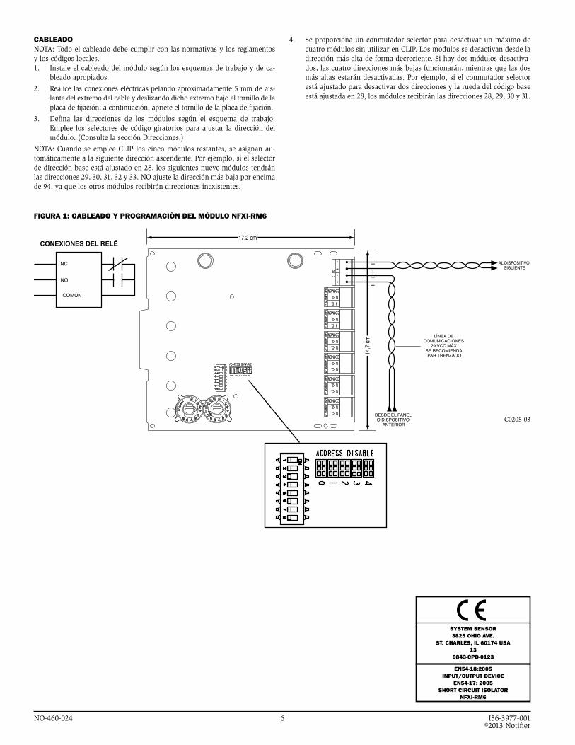
CABLEADONOTA: Todo el cableado debe cumplir con las normativas y los reglamentos y los códigos locales.1. Instale el cableado del módulo según los esquemas de trabajo y de ca-
bleado apropiados.
2. Realice las conexiones eléctricas pelando aproximadamente 5 mm de ais-lante del extremo del cable y deslizando dicho extremo bajo el tornillo de la placa de fijación; a continuación, apriete el tornillo de la placa de fijación.
3. Defina las direcciones de los módulos según el esquema de trabajo. Emplee los selectores de código giratorios para ajustar la dirección del módulo. (Consulte la sección Direcciones.)
NOTA: Cuando se emplee CLIP los cinco módulos restantes, se asignan au-tomáticamente a la siguiente dirección ascendente. Por ejemplo, si el selector de dirección base está ajustado en 28, los siguientes nueve módulos tendrán las direcciones 29, 30, 31, 32 y 33. NO ajuste la dirección más baja por encima de 94, ya que los otros módulos recibirán direcciones inexistentes.
4. Se proporciona un conmutador selector para desactivar un máximo de cuatro módulos sin utilizar en CLIP. Los módulos se desactivan desde la dirección más alta de forma decreciente. Si hay dos módulos desactiva-dos, las cuatro direcciones más bajas funcionarán, mientras que las dos más altas estarán desactivadas. Por ejemplo, si el conmutador selector está ajustado para desactivar dos direcciones y la rueda del código base está ajustada en 28, los módulos recibirán las direcciones 28, 29, 30 y 31.
17,2 cm
14,7
cm
DESDE EL PANEL O DISPOSITIVO
ANTERIOR
LÍNEA DE COMUNICACIONES
29 VCC MÁX.SE RECOMIENDA PAR TRENZADO
AL DISPOSITIVO SIGUIENTE
–+
–+
NC
NO
COMÚN
CONEXIONES DEL RELÉ
6.8"
5.8"
FROM PANELOR PREVIOUS DEVICE
COMMUNICATION LINE32 VDC MAX.
TWISTED PAIRIS RECOMMENDED
TO NEXTDEVICE
–+
–+
–+
NC
NO
COMMON
RELAY CONNECTIONS
FIGURA 1: CABLEADO Y PROGRAMACIÓN DEL MÓDULO NFXI-RM6
C0205-03
EN54-18:2005INPUT/OUTPUT DEVICE
EN54-17: 2005ShORT CIRCUIT ISOLATOR
NFXI-RM6
SYSTEM SENSOR3825 OhIO AVE.
ST. ChARLES, IL 60174 USA13
0843-CPD-0123

NO-460-024 7 I56-3977-001
VOR DER INSTALLATIONDiese Information dient als Kurzanleitung für die Installation. Wenn Module in bereits betriebsbereite Anlagen eingebaut werden, informieren Sie die zustän-digen Personen und die regionalen Behörden, dass die Anlage ggf. zeitweise außer Betrieb genommen wird. Schalten Sie die Zentrale vor dem Beginn der Installationsarbeiten spannungsfrei. Die Anlage beinhaltet Bauteile mit elektro-statischer Empfindlichkeit. Erden Sie sich vor dem Umgang mit diesen Bau-gruppen mit einem geeigneten Erdungsband zur Ableitung der elektrostatischen Energie. Es sollten nur Metallgehäuse mit geeigneter Erdung verwendet werden.
HINWEIS: Diese Anleitung muss vom Eigentümer/Bediener des Geräts ver-wahrt werden. Diese Anleitung bezieht sich nur auf Installationen, die den Anforderungen der EN 54 entsprechen.
ALLGEMEINE BESChREIBUNGDas NFXI-RM6-Steuermodul mit sechs Relais wird in intelligenten Gefahren-meldeanlagen eingesetzt. Jedes Modul ist für Schaltanwendungen der Form C ohne erforderliche Lastkreis-Überwachung ausgelegt. Jedes Modul verfügt über einen getrennten Set von Relaiskontakten, der für jeden Betriebszyklus wahl-weise als Schließer oder Öffner verdrahtet werden kann. Jedes Modul verfügt über von der Zentrale angesteuerte, dreifarbige (grün, rot und gelb) LED-An-zeigen. Über die Zentrale können die LEDs die Zustände blinkend, folgend ein oder folgend aus annehmen. Das Modul verfügt außerdem über Kurzschluss-Isolatoren, damit Kurzschlüsse in der Schleife der Brandmeldeanlage vermieden werden und nicht mehr als einen Teilnehmer in der intelligenten Schleife deak-tivieren.
ADRESSENIn Anlagen mit CLIP-Funktion (Intelligentes Kommunikationsprotokoll) wird die Adresse des ersten Moduls von 01 bis 94 über zwei Drehcodierschalter eingestellt. Den verbleibenden Modulen werden automatisch die fünf näch-sthöheren Adressen zugeordnet. Es besteht die Möglichkeit, maximal vier nicht verwendete Module zu deaktivieren und ihre Adressen anderweitig zu verwenden.
NFXI-RM6 Steuermodul mit sechs RelaisSPEZIFIKATIONBetriebsspannungsbereich: 15 – 29 V DCRuhestrom: 1,45 mAAlarmstrom: 32 mA (bei sechs angesteuerten Relais und sechs dauerleuchtenden LEDs)Temperaturbereich: -10 °C bis 55 °CLuftfeuchtigkeit: 10 % bis 93 % nicht kondensierendAbmessungen: 17,3 x 14,7 x 3,2 (H x B x T in cm)Maximaler Verdrahtungswiderstand IDC: 40 OhmZubehör: Geerdetes MetallgehäuseKabelquerschnitt: 0,8 mm2 - 3,25 mm2 Relaisstrom: 30 mA / pulsierend (Pulsdauer 15,6 ms) von der Zentrale gesteuert
INSTALLATIONS- UND WARTUNGSANLEITUNG
In Anlagen mit erweitertem Protokoll wird die Adresse des Moduls von 01 bis 159 über zwei Drehcodierschalter eingestellt. Für das gesamte Multimodul wird nur eine Adresse verwendet. Dabei werden die verbleibenden Adressen von den Unteradressen vervollständigt.
IM LIEFERUMFANG ENThALTEN:
KOMPATIBILITÄTFür den ordnungsgemäßen Betrieb darf dieses Modul nur an eine kompatible Brandmeldezentrale angeschlossen werden.
Zur Erfüllung der Normen EN 54-17 und EN 54-18 müssen die Module in ei-nem geerdeten Metallgehäuse installiert werden, geeignet für die Anwendung. Das CE-Zeichen bestätigt die Einhaltung der CPD-Richtlinie und darf erst nach Abschluss der Installation auf das Modulgehäuse aufgebracht werden. Das Zeichen muss während der Installation gut sichtbar sein und darf bei War-tungsarbeiten nicht stören. Überkleben sie mit dem Zeichen keine Schrauben oder andere Teile, die einfach zu entfernen sind.
(2) Abstandhalter 3,2 cm
(4) Schrauben
(6) 1 x 3 Anschlussklemmen
(1) 1 x 4 Anschlussklemmen
(2) Muttern
I56-3977-001
RELAISKONTAKTWERTE:
NENNSTROM MAXIMALE SPANNUNG VERBRAUChER ANWENDUNG
2 A 25 V AC PF = 0,35 nicht getaktet
3 A 30 V DC ohmsche Last nicht getaktet
2 A 30 V DC ohmsche Last getaktet
0,46 A 30 V DC (L/R = 20 ms) nicht getaktet
0,7 A 70,7 V AC PF = 0,35 nicht getaktet
0,9 A 125 V DC ohmsche Last nicht getaktet
0,5 A 125 V AC PF = 0,75 nicht getaktet
0,3 A 125 V AC PF = 0,35 nicht getaktet
Notifier by Honeywell.Charles Avenue Burgess Hill
West Sussex RH15 9UF UK

NO-460-024 8 I56-3977-001 ©2013 Notifier
VERDRAhTUNGHINWEIS: Die Verdrahtung muss gemäß den regionalen Auflagen, Richtlinien und Anforderungen ausgeführt werden.1. Installieren Sie das Modul gemäß den Projektierungszeichnungen und
den entsprechenden Anschlussdiagrammen.
2. Für eine elektrische Verbindung müssen Sie ca. 5 cm der Isolierung am Ende des Leiters abisolieren. Schieben Sie das blanke Leiterende unter die Klemmplatte und ziehen die Klemmschraube fest an.
3. Stellen Sie die Adresse auf den Modulen gemäß den Projektierungszeich-nungen ein. Verwenden Sie dazu die Drehcodierschalter (siehe Abschnitt „Adressen“).
HINWEIS: Bei der CLIP-Funktion werden die verbleibenden Module automa-tisch den fünf nächsthöheren Adressen zugeordnet. Wenn der Schalter für die Basisadresse beispielsweise auf 28 eingestellt ist, werden den nächsten fünf Modulen die Adressen 29, 30, 31, 32 und 33 zugeordnet. Stellen Sie die nied-rigste Adresse NIEMALS über 94 ein, weil den anderen Modulen dann nicht vorhandene Adressen zugeordnet werden.
4. Bei der CLIP-Funktion können über einen DIP-Schalter maximal vier nicht verwendete Module deaktiviert werden. Die Deaktivierung der Module erfolgt abwärts, beginnend von der höchsten Adresse. Beim Deaktivieren zweier Module sind die vier niedrigsten Adressen aktiviert und die beiden höchsten deaktiviert. Beispiel: Wenn der DIP-Schalter so eingestellt ist, dass zwei Adressen deaktiviert sind und der Drehcodier-schalter der Basisadresse auf 28 eingestellt ist, werden den Modulen die Adressen 28, 29, 30 und 31 zugeordnet.
6,8"
5,8"
VON DER ZENTRALE ODER DER
VORANGEGANGENEN VORRICHTUNG
KOMMUNIKATIONSLEITUNG, MAX. 29 V�DCVERDRILLTES
LEITERPAAR EMPFOHLEN
ZUR NÄCHSTEN VORRICHTUNG
–+
–+
ÖFFNER
SCHLIESSER
GEMEINSAM
RELAIS-ANSCHLUSS
6.8"
5.8"
FROM PANELOR PREVIOUS DEVICE
COMMUNICATION LINE32 VDC MAX.
TWISTED PAIRIS RECOMMENDED
TO NEXTDEVICE
–+
–+
–+
NC
NO
COMMON
RELAY CONNECTIONS
ABBILDUNG 1: VERDRAhTUNG UND PROGRAMMIERUNG DES NFXI-RM6-MODULS
C0205-03
EN54-18:2005INPUT/OUTPUT DEVICE
EN54-17: 2005ShORT CIRCUIT ISOLATOR
NFXI-RM6
SYSTEM SENSOR3825 OhIO AVE.
ST. ChARLES, IL 60174 USA13
0843-CPD-0123