nfpa 99 leakage current tester - compliance west · pdf file1 section 1 introduction the...
TRANSCRIPT
LCT-601 NFPA 99 Leakage Current Tester
Instruction Manual
COMPLIANCE WESTUSA

i
Dear Customer: Congratulations! Compliance West USA is proud to present you with your LCT-601. This tester is designed to quickly allow testing for Leakage Current in accordance with the requirements of NFPA 99, Sections 8.4.1.3 for Installed Equipment, and NFPA 99, Section 10.2.13.1 for Manufacturer’s Tests. The operating instructions are included in the Manual, so please retain this information for future use. Thank you for your trust and confidence.

ii
Rev. 1.1 May 20, 2005

iii
Table of Contents Introduction .................................................................................................................................................................1 Checkout Procedure....................................................................................................................................................1 LCT-601 for Manufacturers: NFPA 99, Section 10.2.13: Manufacturer’s Tests for Safety of Patient-Care-Related Electrical Appliances...........................................................................................................................3
Paragraph 10.2.13.2: Grounding Circuit Continuity Test......................................................................3 Paragraph 10.2.13.4: Leakage Current from Appliance to Ground .......................................................4 ........................................................................................................................................................................4 Paragraph 10.2.13.5.1: Leakage Current from Patient Connected Leads to Ground (Nonisolated)...............................................................................................................................................5 Paragraph 10.2.13.5.2: Leakage Current from Patient Connected Leads to Ground (Isolated)........6 Paragraph 10.2.13.5.3: Isolation Test (Isolated Input)...........................................................................7 Paragraph 10.2.13.5.4: Between Leads (Nonisolated Input)..................................................................7 Paragraph 10.2.13.5.5: Between Leads (Isolated Input).........................................................................8
LCT-601 for End Users: NFPA 99, Section 8.4.1.3:................................................................................................11 Paragraph 8.4.1.3.2: Grounding Circuit Continuity Test.......................................................................11 Paragraph 8.4.1.3.4: Leakage Current - Fixed Equipment......................................................................12 ........................................................................................................................................................................12 Paragraph 8.4.1.3.5: Leakage Current - Portable Equipment.................................................................13 ........................................................................................................................................................................13 Paragraph 8.4.1.3.6.1: Portable Equipment Lead to Ground – Nonisolated Input Test.....................14 Paragraph 8.4.1.3.6.2: Portable Equipment Lead to Ground – Isolated Input Test............................15 Paragraph 10.2.13.5.3: Isolation Test (Isolated Input) ...........................................................................16 Paragraph 8.4.1.3.6.4: Between Leads (Nonisolated Input)...................................................................16 Paragraph 8.4.1.3.6.5: Between Leads (Isolated Input)..........................................................................17 Paragraph 8.4.2.2.1.1: Leakage Current for Facility Owned Appliances - Portable Equipment.....................................................................................................................................................18 ........................................................................................................................................................................18
Technical Assistance .................................................................................................................................................19 Annual Calibration Information ................................................................................................................................Error! Bookmark not defined.Calibration Instructions..............................................................................................................................................21
Annual Maintenance Check of internal component values .................................................................21

iv
Table of Figures
Figure 1 Grounding Circuit Continuity Test................................................................................................................3 Figure 2 Leakage Current from Appliance to Ground................................................................................................4 Figure 3 Non-isolated Patient Leads ............................................................................................................................5 Figure 4 Isolated Patient Leads.....................................................................................................................................6 Figure 5 Between Leads (Nonisolated)........................................................................................................................7 Figure 6 Between Leads (Nonisolated)........................................................................................................................8 Figure 7 Resistance.......................................................................................................................................................11 Figure 8 Chassis Leakage Current - Fixed Equipment..............................................................................................12 Figure 9 Chassis Leakage Current - Fixed Equipment..............................................................................................13 Figure 10 Nonisolated Lead Leakage Test................................................................................................................14 Figure 11 Leakage Test - Isolated...............................................................................................................................15 Figure 12 Between Leads (Nonisolated)....................................................................................................................16 Figure 13 Between Leads (Isolated Input).................................................................................................................17 Figure 14 Leakage Test for Facility Owned Portable Equipment ...........................................................................18
Table of Tables
Table 1 Grounding Circuit Continuity Test................................................................................................................ 3 Table 2 Leakage Current from Appliance to Ground ................................................................................................ 4 Table 3 Non-isolated Patient Leads............................................................................................................................. 5 Table 4 Isolated Patient Leads ..................................................................................................................................... 6 Table 5 Between Leads (Nonisolated)........................................................................................................................ 7 Table 6 Between Leads (Nonisolated)........................................................................................................................ 9 Table 7 Resistance ....................................................................................................................................................... 11 Table 8 Chassis Leakage Current - Fixed Equipment.............................................................................................. 12 Table 9 Chassis Leakage Current - Fixed Equipment.............................................................................................. 13 Table 10 Nonisolated Lead Leakage Test................................................................................................................. 14 Table 11 Leakage Test - Isolated ............................................................................................................................... 15 Table 12 Between Leads (Nonisolated).................................................................................................................... 16 Table 13 Between Leads (Isolated Input)................................................................................................................. 17 Table 14 Leakage Test for Facility Owned Portable Equipment............................................................................ 18

1
Section 1
Introduction The LCT-601 is designed to facilitate connections as noted in NFPA 99 so tests by manufacturers and users can be made in a fast and repeatable, safe way. Operation Instructions are broken up so manufacturers and end users can go directly to their battery of tests. This Section contains a Checkout Procedure which can be used to check proper switch operation. Section 2 describes use of the LCT-601 by Manufacturers, to verify compliance with the requirements of NFPA 99, Section 10-2.13. Section 3 describes use of the LCT-601 for those requirements for Installed Equipment, both cord connected and permanently connected, in accordance with NFPA 99, Section 8.4.1.3. Section 5 contains annual calibration instructions which can also be used for impromptu checks of proper operation of the LCT-601.
Checkout Procedure In order to verify proper operation of the switches on the LCT-601, this procedure may be used on a periodic basis. In order to facilitate recordkeeping, the procedure is presented on the next page for easier copying if desired.

2
Checkout/Calibration Procedure Rev. 1.3 Compliance West USA LCT-601
Date: _______ Serial Number: __________
Checkout Procedure: can be done periodically to verify correct switch operation Note: The wide parallel slot is the neutral. Switches are numbered 1-4 from the top down. 1. Switches 1-4 in the left position. Measuring from plug to receptacle on the cords:
a. Neutral to Neutral: 0-0.5 ohms: ________ b. Hot to Hot: 0-0.5 ohms: _______ c. Hot to Neutral: open: ? d. Neutral to Hot: open: ? e. Ground to Ground: 0-0.5 ohms: _______ f. Leakage Banana Jack to Leakage Banana Jack: 10 kohm ? 5%: _______
2. Switches 1, 2 and 3 in the left position. Switch 4 in right (Reverse Polarity) position. Measuring from plug to receptacle on the cords: a. Neutral to Neutral: open: ? b. Hot to Hot: open: ? c. Hot to Neutral: 0-0.5 ohms: _______ d. Neutral to Hot: 0-0.5 ohms: _______ e. Ground to Ground: 0-0.5 ohms: _______
3. Switches 1, 2 and 4 in left position. Switch 3 in right (Neutral Open) position. a. Neutral to Neutral: open: ? b. Hot to Hot: 0-0.5 ohms: _____ c. Hot to Neutral: open: ? d. Neutral to Hot: open: ? e. Ground to Ground: 0-0.5 ohms: _______
4. Switches 1, 3 and 4 in left position: Switch 2 in right (Earth - Chassis open) position. a) Neutral to Neutral: 0-0.5 ohms: _______ b) Hot to Hot: 0-0.5 ohms: _______ c) Neutral to Hot: open: ? d) Hot to Neutral: open: ? e) Ground to Ground: 1kohm ? 10% (shunted with 15nF): _______ f) Leakage Banana Jack to Leakage Banana Jack: 11 kohm ? 5%: _______

3
Section 2
LCT-601 for Manufacturers: NFPA 99, Section 10.2.13: Manufacturer’s Tests for Safety of Patient-Care-Related Electrical Appliances
This section describes how to set up and use the LCT-601 to aid in the testing to NFPA 99, Section 10.2.13. Exact setup instructions are included for each test. These instructions are generic in nature and must be checked for accuracy in actual use, and may not reflect NFPA interpretations.
Paragraph 10.2.13.2: Grounding Circuit Continuity Test This test verifies that the grounding lead in grounded equipment is properly connected to the appliance.
1. Connect the LCT-601 to the EUT using the female attachment plug cap pigtail. It is not necessary to connect the LCT-601 to line power to conduct this test.
2. Set the MEAS. POINT switch (top switch) to the CHASSIS MEAS. POINT (left) position.
3. Set the EARTH switch (second switch from the top) to the EARTH-CHASSIS CONNECTED (left) position.
4. Using a calibrated resistance meter, connect one lead to the GREEN banana jack on the LCT-601. Connect the other lead to exposed dead metal or the chassis of the EUT.
5. Flex the cord at its connection to its attachment plug cap and note the reading on the resistance meter.
6. Flex the cord at its connection to the EUT and note the reading on the meter.
7. If the resistance of both tests is less than 0.15 ohm, the result is a PASS. If the resistance of either test is 0.15 ohm or greater, the result is a FAIL.
8. See Test Setup in Fig. 1 and Table 1.
Figure 1 Grounding Circuit Continuity Test
Table 1 Grounding Circuit Continuity Test
Jack/Switch Position FEMALE Cordset To EUT MALE Cordset N/C RED LEAKAGE Jack N/C GREEN LEAKAGE Jack To resistance meter RED RESISTANCE jack N/C MEAS. POINT Switch CHASSIS EARTH Switch CONNECTED NEUTRAL Switch EITHER POSITION POLARITY Switch EITHER POSITION EUT Power Switch EITHER POSITION EUT Chassis or Metal To resistance meter PASS Result: <0.15 ohm

4
Paragraph 10.2.13.4: Leakage Current from Appliance to Ground
1. Connect the LCT-601 to the EUT using the female attachment plug cap pigtail.
2. Connect the LCT-601 to mains power using the male attachment plug cap pigtail.
3. Set the MEAS POINT Switch to the CHASSIS MEAS POINT (left) position.
4. Set the EARTH switch (second switch from the top) to the EARTH-CHASSIS CONNECTED (left) position.
5. Set the NEUTRAL switch (third switch from the top) to the NEUTRAL CONNECTED position.
6. Regarding the POLARITY switch; the test is to be conducted with the POLARITY switch in both positions.
7. Connect a calibrated voltage meter across the RED and GREEN LEAKAGE banana plugs on the LCT-601. Set it to read ~300uV for cord-connected products, or ~5mV for permanently connected products.
8. Connect a lead between the RED LEAKAGE banana plug on the LCT-601 and exposed grounded metal on the EUT.
9. If the EUT does not have exposed metal, connect the probe to a 10x20cm metal foil piece placed in contact with the exposed surface of the EUT.
10. Regarding the power switch of the EUT, the test is to be conducted with the EUT power switch in both the ON and OFF positions.
11. Read the current meter for all four conditions above. A passing result is <300uA (<300uV on the meter connected to the LCT-601) for cord-connected products in the patient care vicinity and < 5mA (<5mV on the meter connected to the LCT-601) for permanently connected products in the patient care facility.
12. See Figure 2 and Table 2 for a Test Setup synopsis. This section is based on NFPA 99 Fig. 10.2.13.4.1, see below. Please note the EUT in Figure 2 displayed a failing result.
Figure 2 Leakage Current from Appliance to Ground
Table 2 Leakage Current from Appliance to Ground
Jack/Switch Position FEMALE Cordset To EUT MALE Cordset To Mains Power RED LEAKAGE Jack To voltage meter
and EUT chassis GREEN LEAKAGE Jack To voltage meter RED RESISTANCE jack N/C MEAS. POINT Switch CHASSIS EARTH Switch OPEN NEUTRAL Switch CONNECTED POLARITY Switch TEST IN BOTH
POSITIONS EUT Power Switch TEST IN BOTH
POSITIONS PASS Result: <300uA cord;
<5mA permanent
FIGURE 10.2.13.4.1 Test Circuit for Measuring Leakage Current from Exposed Conductive Surfaces.
5
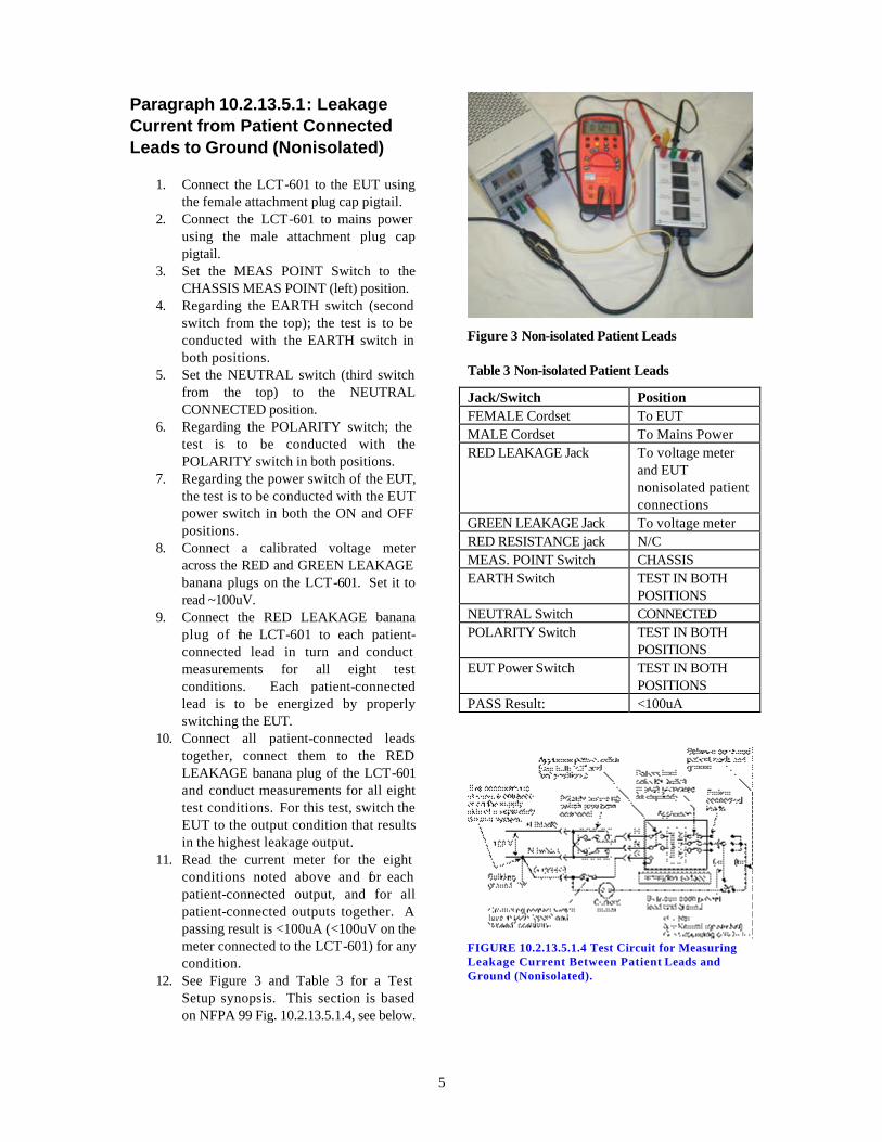
Paragraph 10.2.13.5.1: Leakage Current from Patient Connected Leads to Ground (Nonisolated)
1. Connect the LCT-601 to the EUT using the female attachment plug cap pigtail.
2. Connect the LCT-601 to mains power using the male attachment plug cap pigtail.
3. Set the MEAS POINT Switch to the CHASSIS MEAS POINT (left) position.
4. Regarding the EARTH switch (second switch from the top); the test is to be conducted with the EARTH switch in both positions.
5. Set the NEUTRAL switch (third switch from the top) to the NEUTRAL CONNECTED position.
6. Regarding the POLARITY switch; the test is to be conducted with the POLARITY switch in both positions.
7. Regarding the power switch of the EUT, the test is to be conducted with the EUT power switch in both the ON and OFF positions.
8. Connect a calibrated voltage meter across the RED and GREEN LEAKAGE banana plugs on the LCT-601. Set it to read ~100uV.
9. Connect the RED LEAKAGE banana plug of the LCT-601 to each patient-connected lead in turn and conduct measurements for all eight test conditions. Each patient-connected lead is to be energized by properly switching the EUT.
10. Connect all patient-connected leads together, connect them to the RED LEAKAGE banana plug of the LCT-601 and conduct measurements for all eight test conditions. For this test, switch the EUT to the output condition that results in the highest leakage output.
11. Read the current meter for the eight conditions noted above and for each patient-connected output, and for all patient-connected outputs together. A passing result is <100uA (<100uV on the meter connected to the LCT-601) for any condition.
12. See Figure 3 and Table 3 for a Test Setup synopsis. This section is based on NFPA 99 Fig. 10.2.13.5.1.4, see below.
Figure 3 Non-isolated Patient Leads
Table 3 Non-isolated Patient Leads
Jack/Switch Position FEMALE Cordset To EUT MALE Cordset To Mains Power RED LEAKAGE Jack To voltage meter
and EUT nonisolated patient connections
GREEN LEAKAGE Jack To voltage meter RED RESISTANCE jack N/C MEAS. POINT Switch CHASSIS EARTH Switch TEST IN BOTH
POSITIONS NEUTRAL Switch CONNECTED POLARITY Switch TEST IN BOTH
POSITIONS EUT Power Switch TEST IN BOTH
POSITIONS PASS Result: <100uA
FIGURE 10.2.13.5.1.4 Test Circuit for Measuring Leakage Current Between Patient Leads and Ground (Nonisolated).

6
Paragraph 10.2.13.5.2: Leakage Current from Patient Connected Leads to Ground (Isolated)
1. Connect the LCT-601 to the EUT using the female attachment plug cap pigtail.
2. Connect the LCT-601 to mains power using the male attachment plug cap pigtail.
3. Set the MEAS POINT Switch to the CHASSIS MEAS POINT (left) position.
4. Regarding the EARTH switch (second switch from the top); the test is to be conducted with the EARTH switch in both positions.
5. Set the NEUTRAL switch (third switch from the top) to the NEUTRAL CONNECTED position.
6. Regarding the POLARITY switch; the test is to be conducted with the POLARITY switch in both positions.
7. Regarding the power switch of the EUT, the test is to be conducted with the EUT power switch in both the ON and OFF positions.
8. Connect a calibrated voltage meter across the RED and GREEN LEAKAGE banana plugs on the LCT-601. Set it to read ~100uV.
9. Connect the RED LEAKAGE banana plug of the LCT-601 to each patient-connected lead in turn and conduct measurements for all eight test conditions. Each patient-connected lead is to be energized by properly switching the EUT.
10. Connect all patient-connected leads together, connect them to the RED LEAKAGE banana plug of the LCT-601 and conduct measurements for all eight test conditions. For this test, switch the EUT to the output condition that results in the highest leakage output.
11. Read the current meter for the eight conditions noted above and for each patient-connected output, and for all patient-connected outputs together. A passing result is <10uA (<10uV on the meter connected to the LCT-601) with the GROUND switch in the CONNECTED position, and <50uA (<50uV on the meter connected to the LCT-601) with the GROUND switch in the OPEN position, for any condition.
12. See Figure 4 and Table 4 for a Test Setup synopsis. This section is based on NFPA 99 Fig. 10.2.13.5.2.3, see below.
Figure 4 Isolated Patient Leads
Table 4 Isolated Patient Leads
Jack/Switch Position FEMALE Cordset To EUT MALE Cordset To Mains Power RED LEAKAGE Jack To voltage meter
and EUT isolated patient connections
GREEN LEAKAGE Jack To voltage meter RED RESISTANCE jack N/C MEAS. POINT Switch CHASSIS EARTH Switch TEST IN BOTH
POSITIONS NEUTRAL Switch CONNECTED POLARITY Switch TEST IN BOTH
POSITIONS EUT Power Switch TEST IN BOTH
POSITIONS PASS Result: <10uA ground
connected <50uA ground open

7
FIGURE 10.2.13.5.2.3 Test Circuit for Measuring Leakage Current Between Patient Leads and Ground (Isolated).
Paragraph 10.2.13.5.3: Isolation Test (Isolated Input) Reserved for future use.
Paragraph 10.2.13.5.4: Between Leads (Nonisolated Input)
1. Connect the LCT-601 to the EUT using the female attachment plug cap pigtail.
2. Connect the LCT-601 to mains power using the male attachment plug cap pigtail.
3. Set the MEAS POINT Switch to the FLOATING MEAS POINT (right) position.
4. Regarding the EARTH switch (second switch from the top); the test is to be conducted with the EARTH switch in both positions.
5. Set the NEUTRAL switch (third switch from the top) to the NEUTRAL CONNECTED position.
6. Regarding the POLARITY switch; the test is to be conducted with the POLARITY switch in both positions.
7. The power switch of the EUT is to be ON.
8. Connect a calibrated voltage meter across the RED and GREEN LEAKAGE banana plugs on the LCT-601. Set it to read ~50uV.
9. Connect the BLACK FLOATING MEAS. POINT banana jack on the LCT-601 to a patient-connected lead.
10. Connect the RED LEAKAGE banana plug of the LCT-601 to each patient-
connected lead in turn and conduct measurements for all four test conditions. Each patient-connected lead is to be energized by properly switching the EUT.
11. Testing is done for each patient lead to all other patient leads; that is, each pair combination must be tested.
12. Read the current meter for the four conditions noted above and for each patient-connected output pair. A passing result is <50uA (<50uV on the meter connected to the LCT-601) for any condition.
13. See Figure 6 and Table 6 for a Test Setup synopsis. This section is based on NFPA 99 Fig. 10.2.13.5.4.1, see below.
Figure 5 Between Leads (Nonisolated)
Table 5 Between Leads (Nonisolated)
Jack/Switch Position FEMALE Cordset To EUT MALE Cordset To Mains Power RED LEAKAGE Jack To voltage meter
and EUT nonisolated patient connections
GREEN LEAKAGE Jack To voltage meter RED RESISTANCE jack N/C FLOATING MEAS. PT. EUT nonisolated
patient connections MEAS. POINT Switch FLOATING EARTH Switch TEST IN BOTH
POSITIONS NEUTRAL Switch CONNECTED POLARITY Switch TEST IN BOTH
POSITIONS EUT Power Switch ON PASS Result: <100uA
8
FIGURE 10.2.13.5.4.1 Test Circuit for Measuring Leakage Current Between Patient Leads (Nonisolated and Isolated).
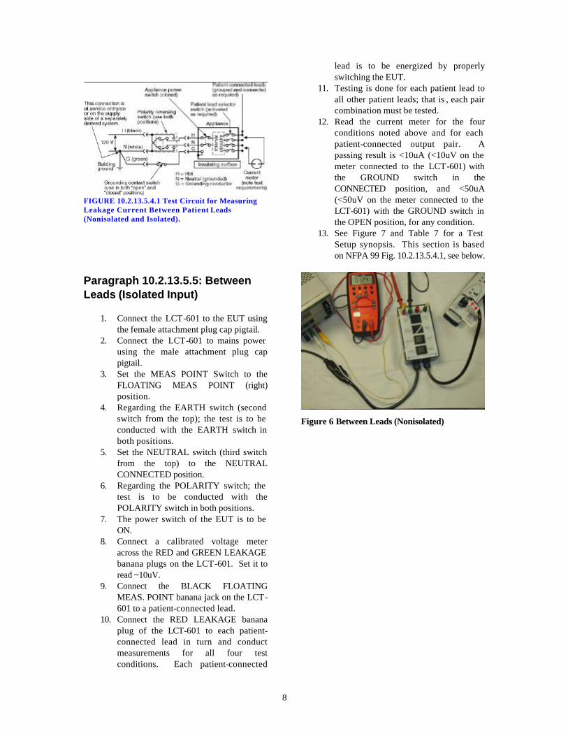
Paragraph 10.2.13.5.5: Between Leads (Isolated Input)
1. Connect the LCT-601 to the EUT using the female attachment plug cap pigtail.
2. Connect the LCT-601 to mains power using the male attachment plug cap pigtail.
3. Set the MEAS POINT Switch to the FLOATING MEAS POINT (right) position.
4. Regarding the EARTH switch (second switch from the top); the test is to be conducted with the EARTH switch in both positions.
5. Set the NEUTRAL switch (third switch from the top) to the NEUTRAL CONNECTED position.
6. Regarding the POLARITY switch; the test is to be conducted with the POLARITY switch in both positions.
7. The power switch of the EUT is to be ON.
8. Connect a calibrated voltage meter across the RED and GREEN LEAKAGE banana plugs on the LCT-601. Set it to read ~10uV.
9. Connect the BLACK FLOATING MEAS. POINT banana jack on the LCT-601 to a patient-connected lead.
10. Connect the RED LEAKAGE banana plug of the LCT-601 to each patient-connected lead in turn and conduct measurements for all four test conditions. Each patient-connected
lead is to be energized by properly switching the EUT.
11. Testing is done for each patient lead to all other patient leads; that is , each pair combination must be tested.
12. Read the current meter for the four conditions noted above and for each patient-connected output pair. A passing result is <10uA (<10uV on the meter connected to the LCT-601) with the GROUND switch in the CONNECTED position, and <50uA (<50uV on the meter connected to the LCT-601) with the GROUND switch in the OPEN position, for any condition.
13. See Figure 7 and Table 7 for a Test Setup synopsis. This section is based on NFPA 99 Fig. 10.2.13.5.4.1, see below.
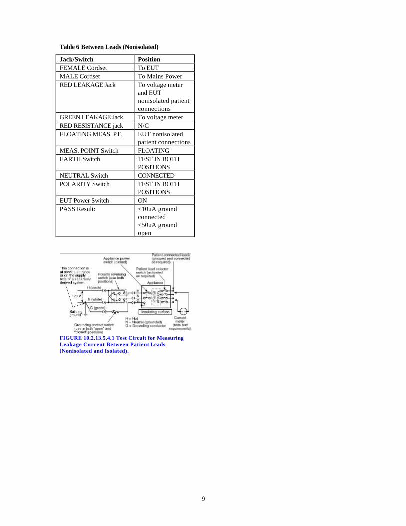
Figure 6 Between Leads (Nonisolated)
9
Table 6 Between Leads (Nonisolated)
Jack/Switch Position FEMALE Cordset To EUT MALE Cordset To Mains Power RED LEAKAGE Jack To voltage meter
and EUT nonisolated patient connections
GREEN LEAKAGE Jack To voltage meter RED RESISTANCE jack N/C FLOATING MEAS. PT. EUT nonisolated
patient connections MEAS. POINT Switch FLOATING EARTH Switch TEST IN BOTH
POSITIONS NEUTRAL Switch CONNECTED POLARITY Switch TEST IN BOTH
POSITIONS EUT Power Switch ON PASS Result: <10uA ground
connected <50uA ground open
FIGURE 10.2.13.5.4.1 Test Circuit for Measuring Leakage Current Between Patient Leads (Nonisolated and Isolated).


11
Section 3
LCT-601 for End Users: NFPA 99, Section 8.4.1.3:
This section describes how to set up and use the LCT-601 to aid in the testing to NFPA 99, Section 8.4.1.3: Testing Requirements-Fixed and Portable. Exact setup instructions are included for each test. These instructions are generic in nature and must be checked for accuracy in actual use, and may not reflect NFPA interpretations.
Paragraph 8.4.1.3.2: Grounding Circuit Continuity Test This test verifies that the grounding lead in grounded equipment is properly connected to the appliance.
9. Connect the LCT-601 to the EUT using the female attachment plug cap pigtail. It is not necessary to connect the LCT-601 to line power to conduct this test.
10. Set the MEAS. POINT switch (top switch) to the CHASSIS MEAS. POINT (left) position.
11. Set the EARTH switch (second switch from the top) to the EARTH-CHASSIS CONNECTED (left) position.
12. Using a calibrated resistance meter, connect one lead to the GREEN banana jack on the LCT-601. Connect the other lead to exposed dead metal or the chassis of the EUT.
13. Flex the cord at its connection to its attachment plug cap and note the reading on the resistance meter.
14. Flex the cord at its connection to the EUT and note the reading on the meter.
15. If the resistance of both tests is less than 0.5 ohm, the result is a PASS. If the resistance of either test is 0.5 ohm or greater, the result is a FAIL.
16. See Test Setup in Fig. 1 and Table 1.
Figure 7 Resistance
Table 7 Resistance
Jack/Switch Position FEMALE Cordset To EUT MALE Cordset N/C RED LEAKAGE Jack N/C GREEN LEAKAGE Jack To resistance meter RED RESISTANCE jack N/C MEAS. POINT Switch CHASSIS EARTH Switch CONNECTED NEUTRAL Switch EITHER POSITION POLARITY Switch EITHER POSITION EUT Power Switch EITHER POSITION EUT Chassis or Metal To resistance meter PASS Result: <0.5 ohm

12
Paragraph 8.4.1.3.4: Leakage Current - Fixed Equipment
1. Connect the LCT-601 to the EUT using the female attachment plug cap pigtail.
2. Connect the LCT-601 to mains power using the male attachment plug cap pigtail.
3. Set the MEAS POINT Switch to the CHASSIS MEAS POINT (left) position.
4. Set the EARTH switch (second switch from the top) to the EARTH-CHASSIS OPEN (right) position.
5. Set the NEUTRAL switch (third switch from the top) to the NEUTRAL CONNECTED position.
6. Set the polarity switch (bottom switch) to the NORMAL position.
7. Connect a calibrated voltage meter across the RED and GREEN LEAKAGE banana plugs on the LCT-601. Set it to read ~5mV for permanently connected products.
8. Connect a lead between the RED LEAKAGE banana plug on the LCT-601 and exposed grounded metal on the EUT.
9. Regarding the power switch of the EUT, the test is to be conducted with the EUT power switch in both the ON and OFF positions.
10. Read the current meter for both conditions above. A passing result is < 5mA (<5mV on the meter connected to the LCT-601) for permanently connected products in the patient care facility.
11. See Figure 9 and Table 9 for a Test Setup synopsis. This section is based on NFPA 99 Fig. 8.4.1.3.5.5, see below.
Figure 8 Chassis Leakage Current - Fixed Equipment
Table 8 Chassis Leakage Current - Fixed Equipment
Jack/Switch Position FEMALE Cordset To EUT MALE Cordset To Mains Power RED LEAKAGE Jack To voltage meter
and EUT chassis GREEN LEAKAGE Jack To voltage meter RED RESISTANCE jack N/C MEAS. POINT Switch CHASSIS EARTH Switch OPEN NEUTRAL Switch CONNECTED POLARITY Switch NORMAL EUT Power Switch TEST IN BOTH
POSITIONS PASS Result: <5mA
FIGURE 8.4.1.3.5.5 Test Circuit for Measuring Chassis Leakage Current.
13
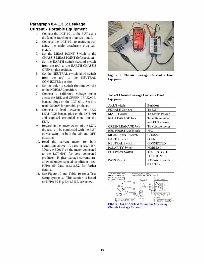
Paragraph 8.4.1.3.5: Leakage Current - Portable Equipment
1. Connect the LCT-601 to the EUT using the female attachment plug cap pigtail.
2. Connect the LCT-601 to mains power using the male attachment plug cap pigtail.
3. Set the MEAS POINT Switch to the CHASSIS MEAS POINT (left) position.
4. Set the EARTH switch (second switch from the top) to the EARTH-CHASSIS OPEN (right) position.
5. Set the NEUTRAL switch (third switch from the top) to the NEUTRAL CONNECTED position.
6. Set the polarity switch (bottom switch) to the NORMAL position.
7. Connect a calibrated voltage meter across the RED and GREEN LEAKAGE banana plugs on the LCT-601. Set it to read ~300mV for portable products.
8. Connect a lead between the RED LEAKAGE banana plug on the LCT-601 and exposed grounded metal on the EUT.
9. Regarding the power switch of the EUT, the test is to be conducted with the EUT power switch in both the ON and OFF positions.
10. Read the current meter for both conditions above. A passing result is < 300uA (<300uV on the meter connected to the LCT-601) for cord connected products. Higher leakage currents are allowed under special conditions; see NFPA 99 Para. 8.4.1.3.5.2 for further details.
11. See Figure 10 and Table 10 for a Test Setup synopsis. This section is based on NFPA 99 Fig. 8.4.1.3.5.5, see below.
Figure 9 Chassis Leakage Current - Fixed Equipment
Table 9 Chassis Leakage Current - Fixed Equipment
Jack/Switch Position FEMALE Cordset To EUT MALE Cordset To Mains Power RED LEAKAGE Jack To voltage meter
and EUT chassis GREEN LEAKAGE Jack To voltage meter RED RESISTANCE jack N/C MEAS. POINT Switch CHASSIS EARTH Switch OPEN NEUTRAL Switch CONNECTED POLARITY Switch NORMAL EUT Power Switch TEST IN BOTH
POSITIONS PASS Result: <300uA or see Para.
8.4.1.3.5.2
FIGURE 8.4.1.3.5.5 Test Circuit for Measuring Chassis Leakage Current.
14
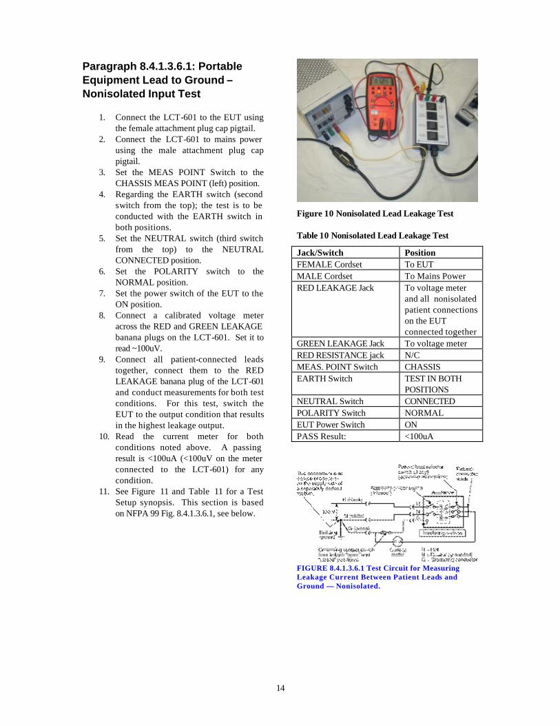
Paragraph 8.4.1.3.6.1: Portable Equipment Lead to Ground – Nonisolated Input Test
1. Connect the LCT-601 to the EUT using the female attachment plug cap pigtail.
2. Connect the LCT-601 to mains power using the male attachment plug cap pigtail.
3. Set the MEAS POINT Switch to the CHASSIS MEAS POINT (left) position.
4. Regarding the EARTH switch (second switch from the top); the test is to be conducted with the EARTH switch in both positions.
5. Set the NEUTRAL switch (third switch from the top) to the NEUTRAL CONNECTED position.
6. Set the POLARITY switch to the NORMAL position.
7. Set the power switch of the EUT to the ON position.
8. Connect a calibrated voltage meter across the RED and GREEN LEAKAGE banana plugs on the LCT-601. Set it to read ~100uV.
9. Connect all patient-connected leads together, connect them to the RED LEAKAGE banana plug of the LCT-601 and conduct measurements for both test conditions. For this test, switch the EUT to the output condition that results in the highest leakage output.
10. Read the current meter for both conditions noted above. A passing result is <100uA (<100uV on the meter connected to the LCT-601) for any condition.
11. See Figure 11 and Table 11 for a Test Setup synopsis. This section is based on NFPA 99 Fig. 8.4.1.3.6.1, see below.
Figure 10 Nonisolated Lead Leakage Test
Table 10 Nonisolated Lead Leakage Test
Jack/Switch Position FEMALE Cordset To EUT MALE Cordset To Mains Power RED LEAKAGE Jack To voltage meter
and all nonisolated patient connections on the EUT connected together
GREEN LEAKAGE Jack To voltage meter RED RESISTANCE jack N/C MEAS. POINT Switch CHASSIS EARTH Switch TEST IN BOTH
POSITIONS NEUTRAL Switch CONNECTED POLARITY Switch NORMAL EUT Power Switch ON PASS Result: <100uA
FIGURE 8.4.1.3.6.1 Test Circuit for Measuring Leakage Current Between Patient Leads and Ground — Nonisolated.

15
Paragraph 8.4.1.3.6.2: Portable Equipment Lead to Ground – Isolated Input Test
1. Connect the LCT-601 to the EUT using
the female attachment plug cap pigtail. 2. Connect the LCT-601 to mains power
using the male attachment plug cap pigtail.
3. Set the MEAS POINT Switch to the CHASSIS MEAS POINT (left) position.
4. Regarding the EARTH switch (second switch from the top); the test is to be conducted with the EARTH switch in both positions.
5. Set the NEUTRAL switch (third switch from the top) to the NEUTRAL CONNECTED position.
6. Set the POLARITY switch to the NORMAL position.
7. Set the power switch of the EUT to the ON position.
8. Connect a calibrated voltage meter across the RED and GREEN LEAKAGE banana plugs on the LCT-601. Set it to read ~10uV.
9. Connect the RED LEAKAGE banana plug of the LCT-601 to each patient-connected lead in turn and conduct measurements for both test conditions. Each patient-connected lead is to be energized by properly switching the EUT.
10. Read the current meter for the eight conditions noted above and for each patient-connected output. A passing result is <10uA (<10uV on the meter connected to the LCT-601) with the GROUND switch in the CONNECTED position, and <50uA (<50uV on the meter connected to the LCT-601) with the GROUND switch in the OPEN position, for any condition.
11. See Figure 4 and Table 4 for a Test Setup synopsis. This section is based on NFPA 99 Fig. 10.2.13.5.2.3, see below.
Figure 11 Leakage Test - Isolated
Table 11 Leakage Test - Isolated
Jack/Switch Position FEMALE Cordset To EUT MALE Cordset To Mains Power RED LEAKAGE Jack To voltage meter
and EUT isolated patient connections each in turn
GREEN LEAKAGE Jack To voltage meter RED RESISTANCE jack N/C MEAS. POINT Switch CHASSIS EARTH Switch TEST IN BOTH
POSITIONS NEUTRAL Switch CONNECTED POLARITY Switch NORMAL EUT Power Switch ON PASS Result: <10uA ground
connected <50uA ground open
FIGURE 8.4.1.3.6.2 Test Circuit for Measuring Leakage Current Between Patient Leads and Ground — Isolated.

16
Paragraph 10.2.13.5.3: Isolation Test (Isolated Input) Reserved for future use.
Paragraph 8.4.1.3.6.4: Between Leads (Nonisolated Input)
1. Connect the LCT-601 to the EUT using the female attachment plug cap pigtail.
2. Connect the LCT-601 to mains power using the male attachment plug cap pigtail.
3. Set the MEAS POINT Switch to the FLOATING MEAS POINT (right) position.
4. Regarding the EARTH switch (second switch from the top); the test is to be conducted with the EARTH switch in both positions.
5. Set the NEUTRAL switch (third switch from the top) to the NEUTRAL CONNECTED position.
6. Set the POLARITY switch to the NORMAL position.
7. The power switch of the EUT is to be ON.
8. Connect a calibrated voltage meter across the RED and GREEN LEAKAGE banana plugs on the LCT-601. Set it to read ~50uV.
9. Connect the BLACK FLOATING MEAS. POINT banana jack on the LCT-601 to a patient-connected lead.
10. Connect the RED LEAKAGE banana plug of the LCT-601 to each patient-connected lead in turn and conduct measurements for all four test conditions. Each patient-connected lead is to be energized by properly switching the EUT.
11. Testing is done for each patient lead to all other patient leads; that is, each pair combination must be tested.
12. Read the current meter for both conditions noted above and for each patient-connected output pair. A passing result is <50uA (<50uV on the meter connected to the LCT-601) for any condition.
13. See Figure 14 and Table 14 for a Test Setup synopsis. This section is based on NFPA 99 Fig. 10.2.13.5.4.1, see below.
Figure 12 Between Leads (Nonisolated)
Table 12 Between Leads (Nonisolated)
Jack/Switch Position FEMALE Cordset To EUT MALE Cordset To Mains Power RED LEAKAGE Jack To voltage meter
and EUT nonisolated patient connections
GREEN LEAKAGE Jack To voltage meter RED RESISTANCE jack N/C FLOATING MEAS. PT. EUT nonisolated
patient connections MEAS. POINT Switch FLOATING EARTH Switch TEST IN BOTH
POSITIONS NEUTRAL Switch CONNECTED POLARITY Switch NORMAL EUT Power Switch ON PASS Result: <50uA
FIGURE 8.4.1.3.6.4 Test Circuit for Measuring Leakage Current Between Patient Leads — Nonisolated and Isolated.
17
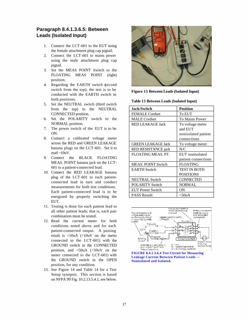
Paragraph 8.4.1.3.6.5: Between Leads (Isolated Input)
1. Connect the LCT-601 to the EUT using the female attachment plug cap pigtail.
2. Connect the LCT-601 to mains power using the male attachment plug cap pigtail.
3. Set the MEAS POINT Switch to the FLOATING MEAS POINT (right) position.
4. Regarding the EARTH switch (second switch from the top); the test is to be conducted with the EARTH switch in both positions.
5. Set the NEUTRAL switch (third switch from the top) to the NEUTRAL CONNECTED position.
6. Set the POLARITY switch to the NORMAL position.
7. The power switch of the EUT is to be ON.
8. Connect a calibrated voltage meter across the RED and GREEN LEAKAGE banana plugs on the LCT-601. Set it to read ~10uV.
9. Connect the BLACK FLOATING MEAS. POINT banana jack on the LCT-601 to a patient-connected lead.
10. Connect the RED LEAKAGE banana plug of the LCT-601 to each patient-connected lead in turn and conduct measurements for both test conditions. Each patient-connected lead is to be energized by properly switching the EUT.
11. Testing is done for each patient lead to all other patient leads; that is, each pair combination must be tested.
12. Read the current meter for both conditions noted above and for each patient-connected output. A passing result is <10uA (<10uV on the meter connected to the LCT-601) with the GROUND switch in the CONNECTED position, and <50uA (<50uV on the meter connected to the LCT-601) with the GROUND switch in the OPEN position, for any condition.
13. See Figure 14 and Table 14 for a Test Setup synopsis. This section is based on NFPA 99 Fig. 10.2.13.5.4.1, see below.
Figure 13 Between Leads (Isolated Input)
Table 13 Between Leads (Isolated Input)
Jack/Switch Position FEMALE Cordset To EUT MALE Cordset To Mains Power RED LEAKAGE Jack To voltage meter
and EUT nonisolated patient connections
GREEN LEAKAGE Jack To voltage meter RED RESISTANCE jack N/C FLOATING MEAS. PT. EUT nonisolated
patient connections MEAS. POINT Switch FLOATING EARTH Switch TEST IN BOTH
POSITIONS NEUTRAL Switch CONNECTED POLARITY Switch NORMAL EUT Power Switch ON PASS Result: <50uA
FIGURE 8.4.1.3.6.4 Test Circuit for Measuring Leakage Current Between Patient Leads — Nonisolated and Isolated.

18
Paragraph 8.4.2.2.1.1: Leakage Current for Facility Owned Appliances - Portable Equipment
1. Connect the LCT-601 to the EUT using the female attachment plug cap pigtail.
2. Connect the LCT-601 to mains power using the male attachment plug cap pigtail.
3. Set the MEAS POINT Switch to the CHASSIS MEAS POINT (left) position.
4. Set the EARTH switch (second switch from the top) to the EARTH-CHASSIS OPEN (right) position.
5. Set the NEUTRAL switch (third switch from the top) to the NEUTRAL CONNECTED position for three-wire (grounded) appliances and double-insulated appliances; and the NEUTRAL OPEN position for two wire appliances that are not double-insulated.
6. Set the polarity switch (bottom switch) to the NORMAL position.
7. Connect a calibrated voltage meter across the RED and GREEN LEAKAGE banana plugs on the LCT-601. Set it to read ~500mV for portable products.
8. Connect a lead between the RED LEAKAGE banana plug on the LCT-601 and exposed grounded metal on the EUT.
9. Regarding the power switch of the EUT, the test is to be conducted with the EUT power switch in both the ON and OFF positions.
10. Read the current meter for both conditions above. A passing result is < 500uA (<500uV on the meter connected to the LCT-601).
11. See Figure 16 and Table 16 for a Test Setup synopsis. This section is based on NFPA 99 Fig. 8.4.1.3.5.5, see below.
Figure 14 Leakage Test for Facility Owned Portable Equipment
Table 14 Leakage Test for Facility Owned Portable Equipment
Jack/Switch Position FEMALE Cordset To EUT MALE Cordset To Mains Power RED LEAKAGE Jack To voltage meter
and EUT chassis GREEN LEAKAGE Jack To voltage meter RED RESISTANCE jack N/C MEAS. POINT Switch CHASSIS EARTH Switch OPEN NEUTRAL Switch CONNECTED;
OPEN for two-wire non-double-insulated only.
POLARITY Switch NORMAL EUT Power Switch TEST IN BOTH
POSITIONS PASS Result: <300uA or see Para.
8.4.1.3.5.2
FIGURE 8.4.1.3.5.5 Test Circuit for Measuring Chassis Leakage Current.

19
Section 4
Technical Assistance
For Technical Assistance Phone: (800) 748-6224 Technical Assistance is available from Compliance West USA between the hours of 8:30 AM and 5:00 PM Pacific Time. Compliance West USA 2120 Jimmy Durante Blvd., Suite 124 Del Mar, CA 92014 Phone: (858) 481-6454 FAX: (858) 481-8527 [email protected]


21
Section 5
Calibration Instructions
Annual Maintenance Check of internal component values
1. Remove the LCT-601 from the case with four screws. 2. Locate the group of jumpers and remove all jumpers. 3. Using a capacitance meter, measure the capacitance from 1 - 1 and verify 15 nF ± 5%.
Replace if outside this tolerance.:_______ 4. Using an ohmmeter, measure the resistance from 2 - 2 and adjust the potentiometer to
achieve a value of 10kohm ± 1%: _______ 5. Using an ohmmeter, measure the resistance from 3 - 3 and adjust the potentiometer to
achieve a value of 1kohm ± 1%: _______ 6. Replace jumpers and put the LCT-601 back in its case: ?