nfc/rfid reader ultra-low-power card presence detect · pdf fileapplication report...
TRANSCRIPT
Application ReportSLOA184–March 2013
NFC and RFID Reader Ultra-Low-Power Card PresenceDetection Using MSP430 and TRF79xxA
Alexander Kozitsky, Josh Wyatt........................................................ MCU Safety and Security ApplicationsJohannes Sturz, Juergen Mayer-Zintel ................................. MSP430 and MCU Safety and Security Systems
ABSTRACT
NFC and RFID reader battery-powered applications must have a defined and limited energy consumptionbudget as well as low cost for a product to be realized. Techniques and strategies have emerged over theyears for the card presence detection that attempt to address both concerns.
The intent of this application report is to contribute to these techniques and strategies by offering anadvancement expressed by adding a simple circuit and small firmware control logic loop to an existingdesign, which offers dramatic improvement over previously identified card detection solutions.
Additionally, a brief overview of the pros and cons of the known and common implementations of battery-powered RFID and NFC readers is given, and in-depth details are provided on the innovative techniqueand approach, developed by Texas Instruments for our customers leveraging both the MSP430 (ultra-lowpower 16-bit MCU) and the TRF79xxA (family of highly integrated NFC/RFID reader/writer ICs) in theirbattery-powered NFC/RFID reader applications and designs.
The firmware that is described in this application report can be downloaded fromhttp://www.ti.com/lit/zip/sloa184.
Contents1 System Design Decisions Criteria ........................................................................................ 22 13.56MHz NFC/RFID Development System ............................................................................ 23 Commonly Implemented NFC/RFID Card Presence Detection ....................................................... 34 Ultra-Low Power (ULP) NFC/RFID Card Presence Detection ........................................................ 65 Firmware Description ..................................................................................................... 146 Measured Current Consumption ........................................................................................ 207 Card Detection and Activation Results ................................................................................. 228 Summary ................................................................................................................... 249 References ................................................................................................................. 24Appendix A TRF7970AEVM Schematic Modifications ..................................................................... 25
List of Figures
1 TRF7970A EVM............................................................................................................. 3
2 Mechanical or Optical Card Slot .......................................................................................... 3
3 Resonator Approach........................................................................................................ 4
4 Capacitive Proximity Sensor Approach .................................................................................. 5
5 TRF79xxA Based RSSI Approach........................................................................................ 5
6 ULP Card Presence Detection and NFC/RFID Reader Circuit ....................................................... 7
7 HF Envelope Detector...................................................................................................... 7
8 Comparator A+ Block Diagram............................................................................................ 8
9 Operational Signals (RF, MOD CONTROL, DEMOD and CAOUT).................................................. 9
10 Circuit for Simulation of Concept ........................................................................................ 10
11 Simulation Results......................................................................................................... 10
12 Entire Card Presence Detection Process .............................................................................. 11
1SLOA184–March 2013 NFC and RFID Reader Ultra-Low-Power Card-Presence Detection UsingMSP430 and TRF79xxASubmit Documentation Feedback
Copyright © 2013, Texas Instruments Incorporated

System Design Decisions Criteria www.ti.com
13 No Card in Field ........................................................................................................... 12
14 NFC Type 2 / ISO14443A Card Detected.............................................................................. 13
15 General Overview Flow Diagram........................................................................................ 14
16 Detailed Firmware Flow (Part A) ........................................................................................ 16
17 Detailed Firmware Flow (Part B) ........................................................................................ 17
18 Current Use During Active Period ....................................................................................... 21
19 ISO15693 Detection and Read Ranges ................................................................................ 22
20 ISO14443A Detection and Read Ranges .............................................................................. 23
21 ISO14443B Detection and Read Ranges .............................................................................. 23
22 Schematic .................................................................................................................. 25
List of Tables
1 Comparator A+ Register Settings ....................................................................................... 20
2 Current Consumption ..................................................................................................... 21
3 Average Current per Polling Frequency ................................................................................ 22
1 System Design Decisions Criteria
Designers and developers of low-power NFC or RFID systems usually have a list of key requirements thatare driven directly by their target markets or focused end equipment. These requirement might include:access control (corporate or industrial building access), digital door locks, "smart" utility meters (forprepayment, technician access, or firmware upgrades), portable speakers, handheld inventory control,handheld data logging collection or medical diagnostic equipment, and mobile or hand-held ticketing orpayment terminals.
All of these end equipment examples have similar key "care-abouts" such as:
• Total system cost must be optimized.
• Electrical design – Platform or modular designs are becoming more prevalent, with emphasis onbeing deployable worldwide – that is, one design that can be used in all countries (like a 13.56MHzsystem based on the TRF79xxA family of devices).
• Mechanical design must be robust, safe, and provide various levels of protection against vandalism.
• User Friendly and Intuitive – NFC/RFID systems are not line of sight, but users should never needmuch training to interact with them, so the design must always lend itself to an easy user experience.
• Low Power Consumption is more important than ever, and when implemented as described later inthis document, can be a real differentiator and competitive advantage.
2 13.56MHz NFC/RFID Development System
The TRF79xxA EVMs (see Figure 1) are self-contained development platforms that can be used toevaluate and test the performance of either the TRF7960A or TRF7970A RFID/NFC transceiver ICs,custom firmware, customer designed antennas, and potential transponders for a customer definedRFID/NFC application. We used these EVMs to demonstrate the concept and so that others could alsoindependently use them to recreate and correlate the findings or make improvements upon them. Thisapplication report is for the system developer.
2 NFC and RFID Reader Ultra-Low-Power Card-Presence Detection Using SLOA184–March 2013MSP430 and TRF79xxA Submit Documentation Feedback
Copyright © 2013, Texas Instruments Incorporated

www.ti.com Commonly Implemented NFC/RFID Card Presence Detection
Figure 1. TRF7970A EVM
For this example, we operated the reader in a completely embedded mode, at +3VDC, instead of at+5VDC. This was intentionally done to show that when using a commonly utilized battery supply voltage,excellent performance can be achieved from both a detection distance and current consumptionperspective, mainly because of the MSP430 (MCU) and the TRF79xxA combination.
3 Commonly Implemented NFC/RFID Card Presence Detection
Mechanical or Optical – A card slot is equipped with a mechanical switch or break beam detector that,when activated, triggers a read cycle of the NFC/RFID card.
Pro: Very low power, consumers and other users are familiar with this interaction.
Con: Card form factor limitations, not robust (easily broken or rendered unusable).
Figure 2. Mechanical or Optical Card Slot
3SLOA184–March 2013 NFC and RFID Reader Ultra-Low-Power Card-Presence Detection UsingMSP430 and TRF79xxASubmit Documentation Feedback
Copyright © 2013, Texas Instruments Incorporated

EN
13.56MHz
1MO
00
0
to antenna switch or
separate HF antenna
From MCU
GPIO
Polling interval
20-50uSec
fo = 13.56MHz
1MO 100pF
BAS21ADC
Oscillator Amplifier Filter
Peak
D
ete
ctio
n
Commonly Implemented NFC/RFID Card Presence Detection www.ti.com
Resonator – The NFC/RFID reader is equipped with an additional resonator, oscillator, or crystal andresonant coil. The MCU enables the signal to be generated as a short burst (20 to 50 µs) and detects theantenna dampening.
Pro: Low power, no additional mechanical components required
Con: Additional electrical components required:
• Two antennas (RFID and Card Sniffer) or switch (capable of handling 13.56MHz signal at power levelsup to +23dBm)
• Second oscillator or crystal with a fast run-in time
• EMC Regulation Compliance (frequency and accuracy)
• Detection Distance
Figure 3. Resonator Approach
4 NFC and RFID Reader Ultra-Low-Power Card-Presence Detection Using SLOA184–March 2013MSP430 and TRF79xxA Submit Documentation Feedback
Copyright © 2013, Texas Instruments Incorporated
fc = 13.56MHz
TRF79xxA
13.56MHz
MCU
Z Matching /
Filtering
SPI or Parallel
TXOUT
RX_IN1
RX_IN2
VDD
VIN
VDD_X VDD_I/O
DC
SUPPLY
(2.7VDC to 5.5VDC)
xxxx
DC
SUPPLY
OSCILLATOR
CT
DC OUTPUT
xxxx
AIR
current
sensor
capacitive
plate
capacitive
plate
(effective)
in target
www.ti.com Commonly Implemented NFC/RFID Card Presence Detection
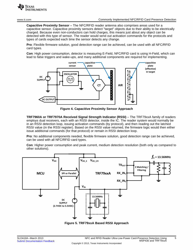
Capacitive Proximity Sensor – The NFC/RFID reader antenna also comprises areas used for acapacitive sensor. Capacitive proximity sensors detect "target" objects due to their ability to be electricallycharged. Because even non-conductors can hold charges, this means just about any object can bedetected with this type of sensor. The reader would send out activation commands for the protocols andtypes of cards expected each time the sensor detects any change.
Pro: Flexible firmware solution, good detection range can be achieved, can be used with all NFC/RFIDcard types.
Con: High power consumption, detector is measuring E-Field, NFC/RFID card is using H-Field, which canlead to false triggers and wake-ups, and many additional components are required for implementing.
Figure 4. Capacitive Proximity Sensor Approach
TRF7960A or TRF7970A Received Signal Strength Indicator (RSSI) – The TRF79xxA family of readersemploys dual receivers, each with an RSSI detector, inside the IC. The reader system would normally bein an RSSI detection loop, issuing activation commands (by protocol), and then reading out the latchedRSSI value (in the RSSI register). Based on the RSSI value returned, the firmware logic would then eitherissue additional commands (for that protocol) or remain in RSSI detection loop.
Pro: No additional components needed, flexible firmware solution, good detection range can be achieved,can be used with all NFC/RFID card types.
Con: Higher power consumption and peak current, medium detection resolution (both only as compared toother solutions).
Figure 5. TRF79xxA Based RSSI Approach
5SLOA184–March 2013 NFC and RFID Reader Ultra-Low-Power Card-Presence Detection UsingMSP430 and TRF79xxASubmit Documentation Feedback
Copyright © 2013, Texas Instruments Incorporated

Ultra-Low Power (ULP) NFC/RFID Card Presence Detection www.ti.com
4 Ultra-Low Power (ULP) NFC/RFID Card Presence Detection
4.1 Introduction
The proposed solution combines some of the older ideas with new approaches. Carefully chosen valuesof the analog circuit components and some MSP430 firmware, which leverages the low power modes andport settings available in the MSP430 itself, with logical loop control of the TRF79xxA power modes arethe main differences. Compared to the implementations listed in earlier sections, the technique outlined inthis section dramatically lowers the power consumption.
The basic idea of this improvement is to combine part of the resonator concept with the existingNFC/RFID reader system based on the TRF79xxA + MSP430. The existing NFC/RFID Reader systemused in this example is the TRF7970AEVM, which has the TRF7970A and the MSP430F2370 or theMSP430G2xx parts that have the MSP430 Comparator A+ module integrated and the ability to accept HFclock in (for synchronization purposes).
4.2 Technical Summary
This card presence detection system senses the card by measuring the decay time of a transmitter signalafter it has been turned off. When a card is in the field of the transmitter, power transfer occurs, and withmore current the voltage on the transmitter output increases. The closer the card is to the reader thehigher the voltage will be from the not present state. Measuring the decay of this signal by a comparatorcreates a simple A/D, since effectively the voltage is what is being measured. Longer times, until theoutput signal crosses a lower threshold, indicate higher voltages and shorter times indicate lower voltages.
This system is created by adding and changing a few components from the original TRF7970A EVM andusing an internal comparator on the MSP430F2370 that was not used before.
The power savings are quite substantial from always running the transmitter. In a system where there arethree polls per second, the system is only active approximately 1% of the time. In the sleep state theTRF79xxA consumes almost no power, while the MSP430 is consuming a negligible amount of current(approximately 0.8 µA). In the active state, which lasts several milliseconds, the TRF7970A is quicklyturned on, initialized, and a transmitter burst is performed. This turns on the transmitter for approximately20 µs. Before it is turned off, the comparator is initialized and a timer is started to measure the time. Thetimer runs until the comparator issues an interrupt indicating that the threshold voltage has been crossed.The timer time at this point is the decay time of the signal. As mentioned earlier, longer times indicatepower coupling, which means that a card may have been in the field.
To determine if a certain time measurement indicates that a card is in the field, it is run through what isreferred as "automatic calibration algorithm". To explain this need, let's examine what would happenwithout it. Without it, a specific time value, that once exceeded, would indicate that a card is in the field.However, due to power supply or temperature drifts, this threshold time would be naturally crossedperiodically, causing false positives. False positives are very undesirable in this system as they cause areading process to happen, which uses a lot of power.
The "automatic calibration algorithm" takes the highest sample that it finds in its history memory buffer andadds THRESHOLD_OFFSET to it. This new value becomes the threshold in determining if the currentsample needs a read to be performed.
6 NFC and RFID Reader Ultra-Low-Power Card-Presence Detection Using SLOA184–March 2013MSP430 and TRF79xxA Submit Documentation Feedback
Copyright © 2013, Texas Instruments Incorporated

fc = 13.56MHz
Transmitter On Time = 20µs
Signal coming from the transmitter
MCU(any MSP430 with
Comparator A+ module)
VDD
CA1
100pF 1.1MO
1.1kO
BAT54WSDICT
(SCHOTTKY)1MO 20pF
30O VIN (2.7V-3.6V)
SYS_CLK
(from TRF79xxA)
COMP_A
CA1
CA0
VDD
p/o COMP_A
internal references
TIMER A
REGISTER (TAR)
CAOUT
fc = 13.56MHz
TRF79xxA
13.56MHz
MCU(any MSP430 with
Comparator A+ module)
Z Matching /
Filtering
SPI or Parallel
TXOUT
RX_IN1
RX_IN2
VDD
VIN
DC
SUPPLY
(2.7V-3.6V)
CA1
100pF1.1MO
1.1kO
BAT54WSDICT
(SCHOTTKY) 1MO 20pF
30O VIN (2.7V-3.6V)
SYS_CLK
(critical)
www.ti.com Ultra-Low Power (ULP) NFC/RFID Card Presence Detection
4.3 Hardware Description
4.3.1 System Overview
Figure 6. ULP Card Presence Detection and NFC/RFID Reader Circuit
Figure 6 shows a high-level overview of the system design. The core of this design is based on theTRF79xxA EVM. Shown here is the complete system. The components in blue indicate which componentsare extra for the card proximity detector circuit.
4.3.2 Detail Sense Circuit
Figure 7 shows the envelope detector plus the RC low pass filter circuit connected to the CA1 input and azoomed in view of the MSP430 COMP_A internals. The COMP_A output (CAOUT) is fed to the Timer Amodule, which is used to measure the CAOUT rising edge timings.
NOTE: With RC feeding CA1 input with zoom on internals of COMP_A
Figure 7. HF Envelope Detector
7SLOA184–March 2013 NFC and RFID Reader Ultra-Low-Power Card-Presence Detection UsingMSP430 and TRF79xxASubmit Documentation Feedback
Copyright © 2013, Texas Instruments Incorporated
Ultra-Low Power (ULP) NFC/RFID Card Presence Detection www.ti.com
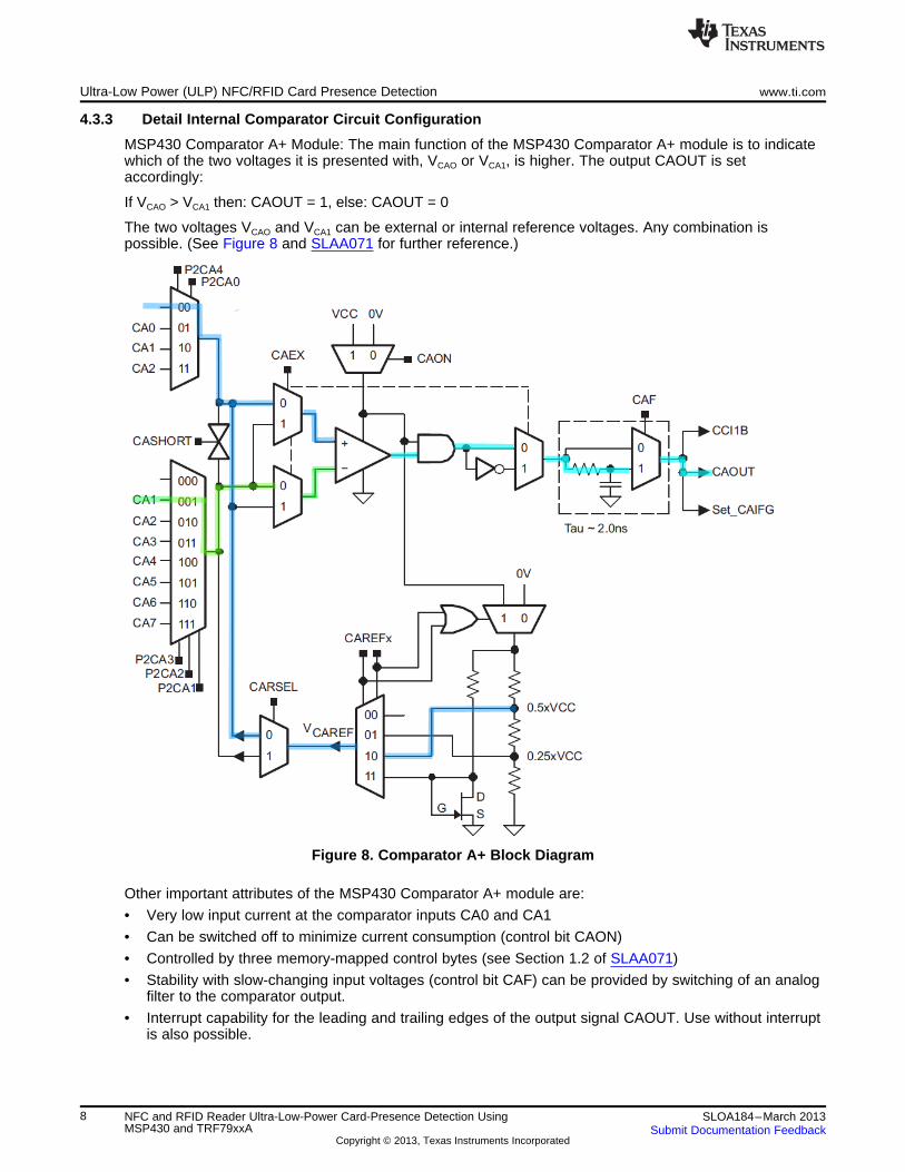
4.3.3 Detail Internal Comparator Circuit Configuration
MSP430 Comparator A+ Module: The main function of the MSP430 Comparator A+ module is to indicatewhich of the two voltages it is presented with, VCAO or VCA1, is higher. The output CAOUT is setaccordingly:
If VCAO > VCA1 then: CAOUT = 1, else: CAOUT = 0
The two voltages VCAO and VCA1 can be external or internal reference voltages. Any combination ispossible. (See Figure 8 and SLAA071 for further reference.)
Figure 8. Comparator A+ Block Diagram
Other important attributes of the MSP430 Comparator A+ module are:
• Very low input current at the comparator inputs CA0 and CA1
• Can be switched off to minimize current consumption (control bit CAON)
• Controlled by three memory-mapped control bytes (see Section 1.2 of SLAA071)
• Stability with slow-changing input voltages (control bit CAF) can be provided by switching of an analogfilter to the comparator output.
• Interrupt capability for the leading and trailing edges of the output signal CAOUT. Use without interruptis also possible.
8 NFC and RFID Reader Ultra-Low-Power Card-Presence Detection Using SLOA184–March 2013MSP430 and TRF79xxA Submit Documentation Feedback
Copyright © 2013, Texas Instruments Incorporated

RF1
MOD
CONTROL
INPUT TO CA1
(DEMOD)CAREF
CAOUT
SAVE TAR CAPTURE TAR
www.ti.com Ultra-Low Power (ULP) NFC/RFID Card Presence Detection
In this ULP Card Presence Detection implementation, the use of the Comparator A+ module is a criticaldetail. Its integration into the MCU guarantees a reduced BOM count compared to the resonator approachpreviously presented. Additionally, the MSP430 firmware control allows a wide range of customization andoptimization.
If for some reason, use of the Comparator A+ choices of 0.7V, 0.25VCC, or 0.5VCC is not possible, anexternal voltage divider may be used. However this will likely result in higher power usage as the internalcomparator efficiently enables the internal voltage divider and disables it when it is not being used.
NOTE: Comparator A+ module is not the only comparator module available in the MSP430 families.Other modules could be used, but most likely would require modification to the firmware thatis provided with this application report.
4.4 Signal Analysis
Figure 9. Operational Signals (RF, MOD CONTROL, DEMOD and CAOUT)
Figure 9 shows a graphical representation of one cycle of the card presence detection process, where theRF Carrier (RF1) is turned on for a short period. During the transmit ON-time, the RC is charging upquickly, when the transmitter is turned OFF, the capacitor C1 begins to discharge and the DEMOD signalis observed to make the measurement.
The circuit was simulated for evaluating and arriving at the correct circuit topology and values needed forthe timing and performance desired. This effort can be seen in Figure 10 and Figure 11. We can see thatthe RC (R1, C1) is charging up to steady state and then fully discharging after the transmit signal is nolonger applied.
9SLOA184–March 2013 NFC and RFID Reader Ultra-Low-Power Card-Presence Detection UsingMSP430 and TRF79xxASubmit Documentation Feedback
Copyright © 2013, Texas Instruments Incorporated

SIMULATION OF
INSIDE COMP A+
Ultra-Low Power (ULP) NFC/RFID Card Presence Detection www.ti.com
Figure 10. Circuit for Simulation of Concept
NOTE: Looking at input to CA1 [red trace] and CAOUT [blue trace].
Figure 11. Simulation Results
The circuit in Figure 6 was constructed on a TRF7970AEVM and firmware was written for theMSP430F2370 (MCU driving the TRF7970A), which is following the general flow outlined in Figure 15. InFigure 11, the red trace represents DEMOD signal that is the feedback coming from the transmitter. Thatis powered on for a brief time and then it is allowed to decay. Once the transmitter is turned off, the timeris started counting until the CAOUT signal is asserted. The count between the transmitter turning off andCAOUT being asserting is the sample time. The EVM was operated at +3VDC, representing the commonvoltage level used in battery-powered applications today (for example, one CR2032, or two AAA, or twoAA, or two C, or two D style batteries in series).
10 NFC and RFID Reader Ultra-Low-Power Card-Presence Detection Using SLOA184–March 2013MSP430 and TRF79xxA Submit Documentation Feedback
Copyright © 2013, Texas Instruments Incorporated

www.ti.com Ultra-Low Power (ULP) NFC/RFID Card Presence Detection
Figure 12. Entire Card Presence Detection Process
Figure 12 shows one entire card presence detection. The EN line is asserted, turning on the TRF79xxA.There is a short delay to configure the TRF79xxA and allow it to initialize itself. Then the transmitter isturned on and a sample is performed after it is turned off. The DEMOD line can be seen as it is goes highand starts to decay. Then the EN pin is turned off and the device goes into sleep mode until the nextactive period.
11SLOA184–March 2013 NFC and RFID Reader Ultra-Low-Power Card-Presence Detection UsingMSP430 and TRF79xxASubmit Documentation Feedback
Copyright © 2013, Texas Instruments Incorporated

Ultra-Low Power (ULP) NFC/RFID Card Presence Detection www.ti.com
Figure 13. No Card in Field
In Figure 13, the pin is asserted, which turns on the transmitter (shown green on channel 3). The senseline (shown red on channel 2) goes high as it monitors the transmitter output. The transmitter is turned offand the sense line starts to decay as the capacitor is being discharged. Eventually the comparator'svoltage threshold is crossed (at approximately 1.5V) and the comparator output (CAOUT, shown in purpleon channel 4) is changed. This interrupts the MCU and the time from the transmitter off to the CAOUTgoing high is taken, which becomes the sample time.
12 NFC and RFID Reader Ultra-Low-Power Card-Presence Detection Using SLOA184–March 2013MSP430 and TRF79xxA Submit Documentation Feedback
Copyright © 2013, Texas Instruments Incorporated

www.ti.com Ultra-Low Power (ULP) NFC/RFID Card Presence Detection
Figure 14. NFC Type 2 / ISO14443A Card Detected
Figure 14 shows an active cycle that is determined to have detected a card. After the active cycle iscompleted, the ISO read cycle is started to read the card.
4.5 System Design Considerations
A common system clock is required. MSP430 must be clocked with SYS_CLK (from TRF79xxA) duringthe sniff period. This is because the system is very sensitive to any changes. Operating the TRF79xxAand MSP430 asynchronously results in random phase changes between the TRF79xxA's SYS_CLK andthe MSP430 clock. These minor time differences are enough to create significant changes in transmitterburst waveform but the worst result is that these changes are random. Having a synchronous systemmeans that the transmitter burst waveform and the sensing mechanism can be repeated almost perfectly.This allows the system to be very sensitive to any changes.
The system can operate from 2.7V to 3.6V. Going higher is not recommended because the analog signalcoming from the TRF79xxA transmitter to the comparator input will reach voltages that are notrecommended to the GPIO coming into the MSP430.
Any changes in the system voltage level (higher or lower) will affect the TRF79xxA's transmitter voltage.This will also affect the RC decay time measured by the comparator. Since the system is very sensitive,false positives will start to occur. Changes as small as 10mV on the power supply voltage can cause falsepositives, thus it is important that a regulator be used. However, if it is not possible to have a regulator,automatic calibration will be needed. The current firmware does have this feature. This feature tracks thesample sense time and adjusts the threshold time that will trigger a read. Thus, the power supply voltagelevel can change gradually and significantly over time and still not cause false positives.
13SLOA184–March 2013 NFC and RFID Reader Ultra-Low-Power Card-Presence Detection UsingMSP430 and TRF79xxASubmit Documentation Feedback
Copyright © 2013, Texas Instruments Incorporated
START
(Device Power-Up)
Card Detection CycleTransmitter is activated which charges up RC
circuit. Timer measures the decay time.
Initial CalibrationRuns through the main loop as configured by
SAMPLES_TO_DISCARD and CALIBRATE_CYCLES
and takes the maximum sample value. It then
adds this value to THRESHOLD_OFFSET and this
becomes the SniffCardTimeThreshold which is the
time if met or exceeded will cause a card read.
This value will be later changed in the automatic
calibration algorithm as needed.
Card Read CycleRead cycle for RFID/NFC cards
Has card been detected?
YES
NO
Automatic Calibration AlgorithmRuns a calculation, based on previous time values,
and determines if the current time value is a card
detect
Firmware Description www.ti.com
5 Firmware Description
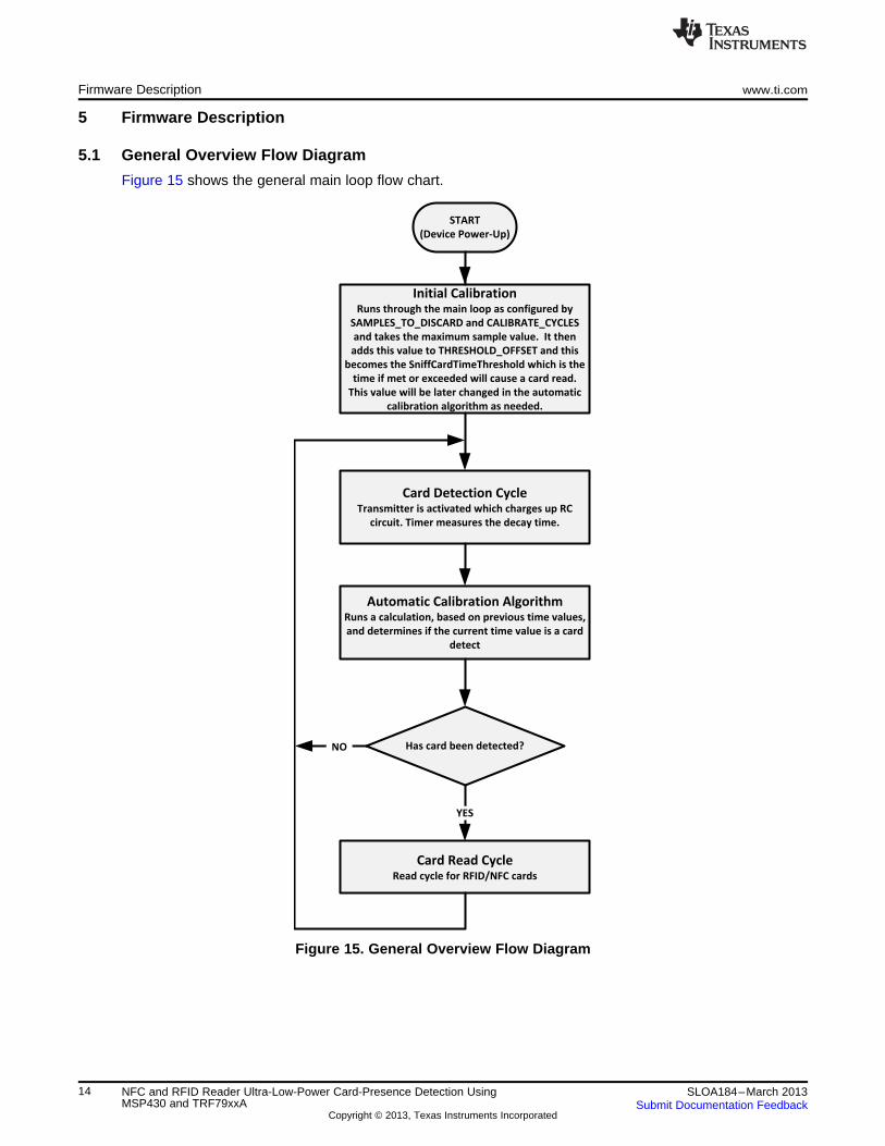
5.1 General Overview Flow Diagram
Figure 15 shows the general main loop flow chart.
Figure 15. General Overview Flow Diagram
14 NFC and RFID Reader Ultra-Low-Power Card-Presence Detection Using SLOA184–March 2013MSP430 and TRF79xxA Submit Documentation Feedback
Copyright © 2013, Texas Instruments Incorporated

www.ti.com Firmware Description
5.2 Firmware Analysis
The following code is the main loop that the program runs through.// infinite loop
while(1){
// we will power down the TRF7970A into Power Down Mode 0 -// (total power down) no clock source will be available to// run the MSP430 thus the internal MCU clock DCO is neededMcuOscSel(DCO_CLOCK_SOURCE);// Running at 8 MHz// Put the TRF into shutdown mode, very little power consumption.// No memory is retained in this stateTRF_DISABLE;// prepare the device for low power stateSetupSleepState ();// clock will be ACLK (at 12kHz), 3996 cycles or ~.333 secondsSetWakeupTimer (SYSTEM_SLEEP_TIME, ACLK_CLOCK);// Timer_B will wake-up the MCU__bis_SR_register(LPM3_bits + GIE);// reset the port settings for operationSetupWakeState ();// reinitialize the SPI moduleTrf797xReConfig();// enable the TRF from low power state into activeTRF_ENABLE;// sleep 50uSSetWakeupTimer (400, SMCLK_CLOCK);// Timer_B will wake-up the MCU__bis_SR_register(LPM0_bits + GIE);// Reinitialize the TRF7970ASniffInitialSettings();// 2.9ms to allow the TRF79xxA to initialize (mainly the crystal)SetWakeupTimer (35, ACLK_CLOCK);// Timer_B will wake-up the device__bis_SR_register(LPM3_bits + GIE);// Initialization for card sniffingInitForCardSniff();// give time for the clock change to stabilize__delay_cycles(50);// set up the system for clock source of the TRF79xxA-// running at 13.56MHzMcuOscSel(TRF_CLOCK_SOURCE);// Pulse the transmitter and record the time the signal crosses the// threshold voltagetime = ComparatorSlopeTime();
if (time == 0){
// this is the case where a timeout occurred in// ComparatorSlopeTime(), return to the startcontinue;
}
// this block only executes on startup and not afterwards// it is for initial calibrationif (Initial_Calibration (time)){
continue; //initial calibration is not complete}// does automatic calibration indicate that a threshold was// exceeded and a read should occur?if (Automatic_Calibration(time, THRESHOLD_OFFSET)){
//do a card read here} }
15SLOA184–March 2013 NFC and RFID Reader Ultra-Low-Power Card-Presence Detection UsingMSP430 and TRF79xxASubmit Documentation Feedback
Copyright © 2013, Texas Instruments Incorporated
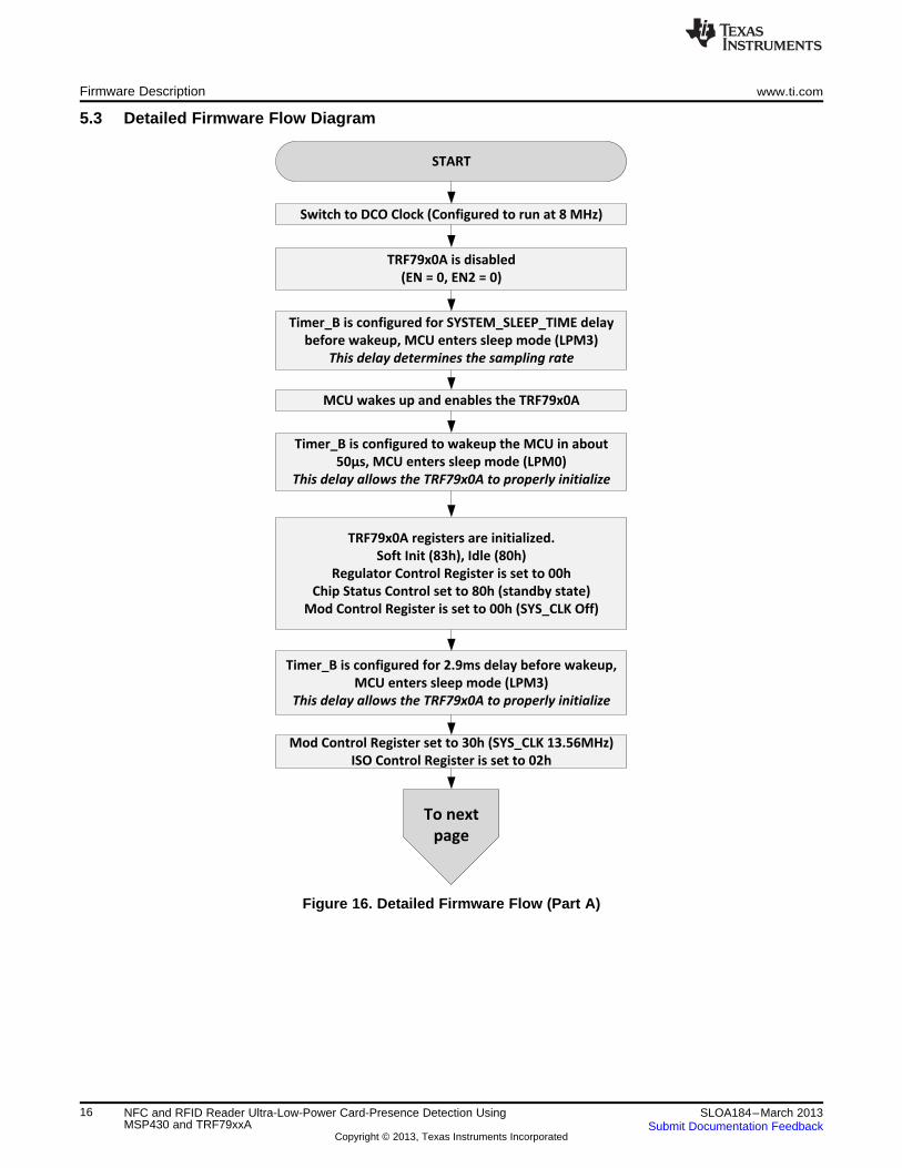
Switch to DCO Clock (Configured to run at 8 MHz)
START
TRF79x0A is disabled
(EN = 0, EN2 = 0)
Timer_B is configured for SYSTEM_SLEEP_TIME delay
before wakeup, MCU enters sleep mode (LPM3)
This delay determines the sampling rate
MCU wakes up and enables the TRF79x0A
Timer_B is configured to wakeup the MCU in about
50µs, MCU enters sleep mode (LPM0)
This delay allows the TRF79x0A to properly initialize
TRF79x0A registers are initialized.
Soft Init (83h), Idle (80h)
Regulator Control Register is set to 00h
Chip Status Control set to 80h (standby state)
Mod Control Register is set to 00h (SYS_CLK Off)
To next
page
Mod Control Register set to 30h (SYS_CLK 13.56MHz)
ISO Control Register is set to 02h
Timer_B is configured for 2.9ms delay before wakeup,
MCU enters sleep mode (LPM3)
This delay allows the TRF79x0A to properly initialize
Firmware Description www.ti.com
5.3 Detailed Firmware Flow Diagram
Figure 16. Detailed Firmware Flow (Part A)
16 NFC and RFID Reader Ultra-Low-Power Card-Presence Detection Using SLOA184–March 2013MSP430 and TRF79xxA Submit Documentation Feedback
Copyright © 2013, Texas Instruments Incorporated

From
previous
page
MCU switches clock to SYS_CLK (13.56 MHz)
TRF79x0A transmitter is activated for 20µs
Timer A (times the sample time), Timer B (exit in case
comparator never interrupts) are started
MCU is in LPM0
mode, waiting for
IRQ
Timeout
Return 0
Halts Timer A,
Returns TAR value
(Timer A count time)
COMP_A
Timer_B
Does Automatic Calibration
Algorithm indicate a read is
necessary?
TAR
Performs polling cycle for
NFC/RFID Cards
Return to
Start
YES
NO
Comparator A+ and Timer A are initialized
www.ti.com Firmware Description
Figure 17. Detailed Firmware Flow (Part B)
17SLOA184–March 2013 NFC and RFID Reader Ultra-Low-Power Card-Presence Detection UsingMSP430 and TRF79xxASubmit Documentation Feedback
Copyright © 2013, Texas Instruments Incorporated
Firmware Description www.ti.com
5.4 Description of User Modifiable Parameters• MOVING_WINDOW_WHERE_MAXIMUM_SAMPLE_IS_COMPENSATED_FOR
This variable essentially decides what the remembering capability of the algorithm is. How long it willkeep a certain value for in memory. Samples that have aged past this value are no longer valid. So forexample, setting this parameter to 60 will cause the algorithm to keep the recent sample, if it issignificant, for at most the next 60 samples.
Recommended starting value: 60
For a sampling rate of three times per second, the memory length of the algorithm is 60/3 orapproximately 20 seconds.
• NUMBER_OF_MAXIMUM_VALUES_TO_TRACK
This value determines the actual memory buffer size. It does not have to be the exact size ofMOVING_WINDOW_WHERE_MAXIMUM_SAMPLE_IS_COMPENSATED_FOR, because thealgorithm does some optimization on how it stores the significant samples that it receives in the buffer.This parameter should be approximately 1/2 ofMOVING_WINDOW_WHERE_MAXIMUM_SAMPLE_IS_COMPENSATED_FOR but no less than 3 or4 times THRESHOLD_OFFSET.
Recommended starting value: 30
• THRESHOLD_OFFSET
This parameter determines the margin that is between the no-card sample state and detectionthreshold. If a new sample is equal or greater than no card value plus THRESHOLD_OFFSET, then aread is initiated. If this value is too low, false positives can occur. Too high and detection range will bereduced.
Recommended starting value: 3
• DELAY_LINE_NUMBER_OF_SAMPLES
This determines the size of the delay line. Samples that come into the delay line are not acted on untilthey exit the delay line. They exit into the algorithm. The delay is needed so that it can all be set to theoldest value in it immediately once a card read has been detected. This is so that the activity leadingup to the card read is not used by the calibration routine so to prevent any corruption of it.
Recommended starting value: 15
Using this setting, for a sampling rate of three times per second, the delay line will delay a sample justtaken for five seconds.
• IGNORE_SAMPLES_AFTER_READ
This determines the number of samples after a read has been performed until the next possibledetection or read. This is needed to both save power on repetitive reads, as well as prevent anydetection while the card is still in the proximity of the reader and thus influencing the automaticcalibration algorithm.
Recommended starting value: 9
For a sampling rate of three times per second, the next possible read or detection after a read wouldbe in three seconds.
• SYSTEM_SLEEP_TIME
This parameter times 1/12000 is the time that the system spends in the main sleeping period. Thereciprocal of this time is the sample frequency of the system.
• SAMPLES_TO_DISCARD
This parameter determines, in the initial calibration algorithm – not the automatic one, how many initialsamples to not use in calibration.
• CALIBRATE_CYCLES
This parameter determines how many cycles are used in the initial calibration.
• USE_AUTOMATIC_CALIBRATION
If defined, automatic calibration is used. If not, uses only the calibration value from the initialcalibration. If device drifts, false positives are possible. This is useful for testing detection ranges.
18 NFC and RFID Reader Ultra-Low-Power Card-Presence Detection Using SLOA184–March 2013MSP430 and TRF79xxA Submit Documentation Feedback
Copyright © 2013, Texas Instruments Incorporated

www.ti.com Firmware Description
5.5 Automatic Calibration Algorithm
Automatic calibration changes the detection threshold based on the previous values that it has received.The algorithm searches the buffer for the maximum time value, adds THRESHOLD_OFFSET to it, andthis becomes the threshold that, if met or exceeded, will determine if a read is performed.
It stores a certain amount of samples in a buffer that ages the samples. The samples that are older thanMOVING_WINDOW_WHERE_MAXIMUM_SAMPLE_IS_COMPENSATED_FOR are erased and makeway for new sample values. It is important to have a finite recent memory for two reasons. First anycorruption of the calibration will be in effect for a finite period of time. Also a limited memory is very muchnecessary when working on value line devices.
NUMBER_OF_MAXIMUM_VALUES_TO_TRACK sets the actual buffer size.MOVING_WINDOW_WHERE_MAXIMUM_SAMPLE_IS_COMPENSATED_FOR may be greater thanNUMBER_OF_MAXIMUM_VALUES_TO_TRACK. The algorithm is able to optimize which high timevalues that it stores in the buffer so the buffer size may be less than the "window" that it is tracking. Agood rule of thumb is to make NUMBER_OF_MAXIMUM_VALUES_TO_TRACK approximately 1/2 of thesize of MOVING_WINDOW_WHERE_MAXIMUM_SAMPLE_IS_COMPENSATED_FOR but at least threeor four times the value of THRESHOLD_OFFSET.
Also there are mechanisms in the algorithm to prevent the corruption of the calibration algorithm. As eachsample makes its way into the algorithms, it enters a delay line. The sample length of the delay line is setby DELAY_LINE_NUMBER_OF_SAMPLES. Anything entering the delay line is shifted from one end tothe other. If a value makes it through the delay line, it enters the algorithm computation and calibration isperformed. The reason that a delay line is necessary is because if a user presents a card to a reader,there may be several detections before a read is performed. These detections, if not cleared, will causethe algorithm to adjust them out, eventually causing poor detection range. What happens in the currentsystem is that once a read has been detected, this delay line is flushed by setting all values to the oldestvalue. It is expected that the time from the first detection to the read be no longer thanDELAY_LINE_NUMBER_OF_SAMPLES / samples per second.
When a read has been detected, IGNORE_SAMPLES_AFTER_READ determines how many samples arethrown out afterwards. This prevents multiple reads or detections where the card is still in the field andthus corrupting the automatic calibration. It is expected that after IGNORE_SAMPLES_AFTER_READsamples, the user has removed the card from the reader detection range.
If these attempts to prevent erroneous samples from making it into the calibration algorithm do not work(for example, if the user has a hard time getting a read and keeps the card so long that the detectionsmake their way through the delay line, or does a detection without a read) the algorithm is corrupted for awhile. During that time, the detection and effectively read range are reduced. However, when the memoryhas been refreshed, after the erroneous value is aged out of the buffer, newer ones will come into effect,thus restoring the detection range once more.
The time for a complete memory refresh to happen isMOVING_WINDOW_WHERE_MAXIMUM_SAMPLE_IS_COMPENSATED_FOR / samples per second.
5.6 Testing the Device
To test a device, there is a rule that should be followed for normal operation. First, the automaticcalibration will compensate out any noise that it sees. This also means card detections. When it does this,the detection range decreases. To prevent this loss of range on card detections, it is important to do aread within DELAY_LINE_NUMBER_OF_SAMPLES / samples per second seconds. When a read isperformed, the samples in the delay buffer are set to its oldest value, thus preventing any corruption sincethey never get to the algorithm.
It should be noted that after a read, for IGNORE_SAMPLES_AFTER_READ / samples per secondseconds there will be no possible detections or reads. This is necessary so that multiple reads are notperformed and also allow the user to remove the card from the reader to prevent any more detections,which as mentioned before, would cause reduction of detection range.
19SLOA184–March 2013 NFC and RFID Reader Ultra-Low-Power Card-Presence Detection UsingMSP430 and TRF79xxASubmit Documentation Feedback
Copyright © 2013, Texas Instruments Incorporated

Measured Current Consumption www.ti.com
5.7 Firmware Considerations
As can be seen in the detection and read range results in Figure 19, Figure 20, and Figure 21, there canbe a significant difference in the detection and read range. An issue may occur where a card is detected,but the initial read cycle cannot read it because it has not reached the read range. This issue may becorrect by increasing the THRESHOLD_OFFSET parameter. This will decrease detection range, bringingit closer to the read range – if so desired.
5.8 Comparator A+ Register Settings
This is the configuration that is used to measure the decay time of the output signal. These values areimportant to study if another type of comparator is needed to be used. Also for aid in interpreting theseconfigurations, see Figure 8.
Table 1. Comparator A+ Register Settings
Comparator A+ Value DescriptionRegister
CACTL1
CAEX 0 No invert
CARSEL 0 V_CAREF is applied to the + terminal
CAREF 2 Voltage reference set to 0.5VCC
CAON 1 Comparator enabled at sampling period
CAIES 0 Rising edge interrupt
CAIE 1 Comparator interrupt is enabled for sampling
CAIFG X Indicates that a comparator interrupt has occurred
CACTL2
CASHORT 0 Inputs are not shorted
P2CA4 0 Positive input is routed to high-impedance input pin
P2CA3 0 Negative input is routed to CA1 input pin
P2CA2 0 See above
P2CA1 1 See above
P2CA0 0 See above
CAF 1 Comparator output is filtered
CAPD
CAPD1 1 Pin CA1 input buffer is disabled
CAPDX 0 The rest of the input buffers are not disabled
6 Measured Current Consumption
Figure 18 shows a breakdown of current consumption during each stage or step during the card presencedetection monitor process for running the process three times in one second. This is where the three timesa second interval (approximately 336 ms) is coming from, and if it needs to be sped up or slowed down,this is simple change to make. Also, in the case of building access systems that are "learning" theoccupant's behaviors and adjusting energy consumption accordingly, this would be the variable that thefirmware algorithm would be changing.
20 NFC and RFID Reader Ultra-Low-Power Card-Presence Detection Using SLOA184–March 2013MSP430 and TRF79xxA Submit Documentation Feedback
Copyright © 2013, Texas Instruments Incorporated

www.ti.com Measured Current Consumption
Figure 18. Current Use During Active Period
The first spike of the current graph is where the bypass capacitors are being instantaneously charged.Immediately afterwards is the TRF79xxA initialization and then the sleep period. The last spike is for theactual RF carrier transmitter burst and the sampling period afterwards.
Table 2. Current Consumption (1)
AverageCycle Name Time Description Of ProcessCurrent
Main Sleep Cycle 333 ms 0.8 µA Time determines polling frequency
A TRF79xxA Enable 56 µs 27.4 mA TRF79xxA is enabled
B Configure TRF79xxA 88 µs 8.45 mA SPI communication
C Initialization Sleep Cycle 2.736 ms 1.45 mA Sleep cycle for crystal to turn on
D Next Init, Clock Switch 232 µs 2.28 mA MCU starts to be sourced by TRF79xxA's clock
304 µsE Sampling Cycle 6.01 mA Transmitter burst and sampling488 µs (2)
Total Period 336.4 ms(1) Assumption: VCC = 3.0V, Polling: three times per second(2) 304 µs is the time until de-assertion of EN signal. 488 µs is the time until current from active cycle returns to normal (using 304
µs).
21SLOA184–March 2013 NFC and RFID Reader Ultra-Low-Power Card-Presence Detection UsingMSP430 and TRF79xxASubmit Documentation Feedback
Copyright © 2013, Texas Instruments Incorporated
0
2
4
6
8
10
12
16mm
(Positag)
RI-I16-11xA-xx
(24.2mm)
RI-HDT-DVBx
(22mm)
RI-I03-11xA-xx
(22.5mm x
38mm)
RI-I17-11xA-xx
(32.5mm)
RI-I11-11xA/B-xx
(45mm x 45mm)
RI-I15-112B-03
(34mm x 65mm)
RI-I02-11xA/B-xx
(45mm x 76mm)
ISO15693 Transponder Detection Ranges and UID Read Ranges
ISO15693 Card Detection Range (cm) ISO15693 UID Read Range (cm)
Card Detection and Activation Results www.ti.com
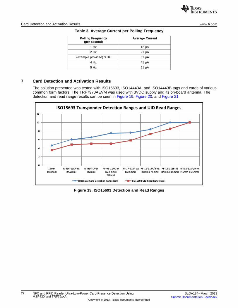
Table 3. Average Current per Polling Frequency
Polling Frequency Average Current(per second)
1 Hz 12 µA
2 Hz 21 µA
(example provided) 3 Hz 31 µA
4 Hz 41 µA
5 Hz 51 µA
7 Card Detection and Activation Results
The solution presented was tested with ISO15693, ISO14443A, and ISO14443B tags and cards of variouscommon form factors. The TRF7970AEVM was used with 3VDC supply and its on-board antenna. Thedetection and read range results can be seen in Figure 19, Figure 20, and Figure 21.
Figure 19. ISO15693 Detection and Read Ranges
22 NFC and RFID Reader Ultra-Low-Power Card-Presence Detection Using SLOA184–March 2013MSP430 and TRF79xxA Submit Documentation Feedback
Copyright © 2013, Texas Instruments Incorporated

0
2
4
6
8
10
12
22.5mm x 38mm 22mm x 52mm 22.5mm x 79mm 45mm x 76mm
ISO14443B Transponder Detection Ranges and UID Read Ranges
Card Detection Range (cm) PUPI Read Range (cm)
0
1
2
3
4
5
6
7
8
9
10
20mm x 28mm
(half moon)
20mm 22mm 30mm 32mm x 32mm 34mm 40mm 45mm x 76mm 45mm x 76mm
ISO14443A Transponder Detection Ranges and UID Read Ranges
Card Detection Range (cm) UID Read Range (cm)
www.ti.com Card Detection and Activation Results
NOTE: Regarding low read ranges seen in this figure, the 32mm x 32mm inlay is a Mifare Ultra Light C devicewith a measured low Q, 34mm circular inlay was made from NTAG203 with a measured resonant frequencyof 14.62MHz, 45mm x 76mm tag is a DESFire EV1 inlay with a measured resonant frequency of 15.275MHz.These are devices purchased or obtained through public distribution channels and could have been designedand/or manufactured with higher quality control. The point here is that most likely the poor read range is notthe fault of the IC maker, but the inlay manufacturer. In Figure 19, the TI inlay quality is high and controlledand, thus, the detection and read ranges track each other in a more linear fashion.
Figure 20. ISO14443A Detection and Read Ranges
Figure 21. ISO14443B Detection and Read Ranges
Assumptions for these range tests: THRESHOLD_OFFSET was set to 4.USE_AUTOMATIC_CALIBRATION was not defined. Device was being reset periodically to run throughthe initial calibration.
23SLOA184–March 2013 NFC and RFID Reader Ultra-Low-Power Card-Presence Detection UsingMSP430 and TRF79xxASubmit Documentation Feedback
Copyright © 2013, Texas Instruments Incorporated

Summary www.ti.com
8 Summary
It is critical to realize that average current consumption goes down as the wait times in between thedetection cycles are made longer. Most competitive parts that might be claiming to have card detectionbuilt in are most likely putting out a voltage on their antenna coil (like we are), but then they are using aDAC to measure current changes. Here we are putting out a voltage and measuring a change in thatvoltage directly using the Comparator_A+ and timer hardware that is already built in to the MSP430 MCU.Using this approach, we can achieve lower power consumption by comparison and only get better as timein between "sniff" cycles is increased.
Using a standard TRF79xxA EVM and adding few passive components, a highly power efficient systemmay be realized. This system may allow its use in battery powered applications with very little added extracost.
Along with an automatic calibrating algorithm, voltage or temperature drifts do not cause unnecessaryfalse positives and thus conserve power.
For developers of NFC/RFID systems that operate from battery power or need to conserve energy asmuch as possible as part of their value proposition to the end customer/consumer, the superior cardpresence detection solution outlined in this document, using the TRF79xxA and an MSP430 in conjunctionwith the firmware approach, is the path to achieving the ultra low power operations in their application.
9 References• TRF7970A Data Sheet (SLOS743)
• MSP430F23x0 Data Sheet (SLAS518)
• MSP430G2xx Family (MSP430G2xx Family)
• MSP430x2xx Family User's Guide (SLAU144)
• Economic Measurement Techniques With the Comparator_A Module (SLAA071)
• ISO/IEC15693-2 (ISO/IEC15693-2)
ISO/IEC15693-3 (ISO/IEC15693-3)
ISO/IEC14443-2, -3, -4 (ISO/IEC14443-2, ISO/IEC14443-3, ISO/IEC14443-4)
24 NFC and RFID Reader Ultra-Low-Power Card-Presence Detection Using SLOA184–March 2013MSP430 and TRF79xxA Submit Documentation Feedback
Copyright © 2013, Texas Instruments Incorporated
www.ti.com
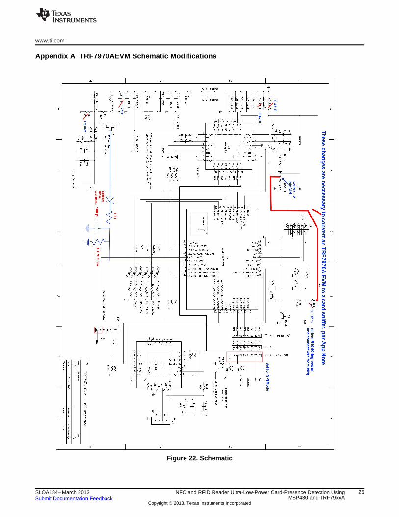
Appendix A TRF7970AEVM Schematic Modifications
Figure 22. Schematic
25SLOA184–March 2013 NFC and RFID Reader Ultra-Low-Power Card-Presence Detection UsingMSP430 and TRF79xxASubmit Documentation Feedback
Copyright © 2013, Texas Instruments Incorporated

IMPORTANT NOTICE
Texas Instruments Incorporated and its subsidiaries (TI) reserve the right to make corrections, enhancements, improvements and otherchanges to its semiconductor products and services per JESD46, latest issue, and to discontinue any product or service per JESD48, latestissue. Buyers should obtain the latest relevant information before placing orders and should verify that such information is current andcomplete. All semiconductor products (also referred to herein as “components”) are sold subject to TI’s terms and conditions of salesupplied at the time of order acknowledgment.
TI warrants performance of its components to the specifications applicable at the time of sale, in accordance with the warranty in TI’s termsand conditions of sale of semiconductor products. Testing and other quality control techniques are used to the extent TI deems necessaryto support this warranty. Except where mandated by applicable law, testing of all parameters of each component is not necessarilyperformed.
TI assumes no liability for applications assistance or the design of Buyers’ products. Buyers are responsible for their products andapplications using TI components. To minimize the risks associated with Buyers’ products and applications, Buyers should provideadequate design and operating safeguards.
TI does not warrant or represent that any license, either express or implied, is granted under any patent right, copyright, mask work right, orother intellectual property right relating to any combination, machine, or process in which TI components or services are used. Informationpublished by TI regarding third-party products or services does not constitute a license to use such products or services or a warranty orendorsement thereof. Use of such information may require a license from a third party under the patents or other intellectual property of thethird party, or a license from TI under the patents or other intellectual property of TI.
Reproduction of significant portions of TI information in TI data books or data sheets is permissible only if reproduction is without alterationand is accompanied by all associated warranties, conditions, limitations, and notices. TI is not responsible or liable for such altereddocumentation. Information of third parties may be subject to additional restrictions.
Resale of TI components or services with statements different from or beyond the parameters stated by TI for that component or servicevoids all express and any implied warranties for the associated TI component or service and is an unfair and deceptive business practice.TI is not responsible or liable for any such statements.
Buyer acknowledges and agrees that it is solely responsible for compliance with all legal, regulatory and safety-related requirementsconcerning its products, and any use of TI components in its applications, notwithstanding any applications-related information or supportthat may be provided by TI. Buyer represents and agrees that it has all the necessary expertise to create and implement safeguards whichanticipate dangerous consequences of failures, monitor failures and their consequences, lessen the likelihood of failures that might causeharm and take appropriate remedial actions. Buyer will fully indemnify TI and its representatives against any damages arising out of the useof any TI components in safety-critical applications.
In some cases, TI components may be promoted specifically to facilitate safety-related applications. With such components, TI’s goal is tohelp enable customers to design and create their own end-product solutions that meet applicable functional safety standards andrequirements. Nonetheless, such components are subject to these terms.
No TI components are authorized for use in FDA Class III (or similar life-critical medical equipment) unless authorized officers of the partieshave executed a special agreement specifically governing such use.
Only those TI components which TI has specifically designated as military grade or “enhanced plastic” are designed and intended for use inmilitary/aerospace applications or environments. Buyer acknowledges and agrees that any military or aerospace use of TI componentswhich have not been so designated is solely at the Buyer's risk, and that Buyer is solely responsible for compliance with all legal andregulatory requirements in connection with such use.
TI has specifically designated certain components as meeting ISO/TS16949 requirements, mainly for automotive use. In any case of use ofnon-designated products, TI will not be responsible for any failure to meet ISO/TS16949.
Products Applications
Audio www.ti.com/audio Automotive and Transportation www.ti.com/automotive
Amplifiers amplifier.ti.com Communications and Telecom www.ti.com/communications
Data Converters dataconverter.ti.com Computers and Peripherals www.ti.com/computers
DLP® Products www.dlp.com Consumer Electronics www.ti.com/consumer-apps
DSP dsp.ti.com Energy and Lighting www.ti.com/energy
Clocks and Timers www.ti.com/clocks Industrial www.ti.com/industrial
Interface interface.ti.com Medical www.ti.com/medical
Logic logic.ti.com Security www.ti.com/security
Power Mgmt power.ti.com Space, Avionics and Defense www.ti.com/space-avionics-defense
Microcontrollers microcontroller.ti.com Video and Imaging www.ti.com/video
RFID www.ti-rfid.com
OMAP Applications Processors www.ti.com/omap TI E2E Community e2e.ti.com
Wireless Connectivity www.ti.com/wirelessconnectivity
Mailing Address: Texas Instruments, Post Office Box 655303, Dallas, Texas 75265Copyright © 2013, Texas Instruments Incorporated