next-generation ultra-lean burn powertrainhugh blaxill, pi . michael bunce, presenter . mahle...
TRANSCRIPT

Hugh Blaxill, PI
Michael Bunce, Presenter
MAHLE Powertrain, LLC
5/16/2013
Project ID: ACE087
Next-Generation Ultra Lean Burn Powertrain
This presentation does not contain any proprietary, confidential, or otherwise restricted information 1

MAHLE Powertrain LLC, 16-May-2013 2
Overview
Project Outline
Timeline Start Date: February 1, 2012
End Date: January 31, 2015
Percent Complete: 33%
Project Goals/ACE Barriers Addressed 45% thermal efficiency on a light duty SI engine
with emissions comparable to or below existing SI engines (A, B, C, D, F)
30% predicted drive cycle fuel economy improvement over comparable gasoline engine vehicle (A, C, H)
Cost effective system requiring minimal modification to existing hardware (G)
Budget
Contract Value (80/20): $ 3,172,779 Gov’t Share: $ 2,499,993 MPT Share: $ 672,796
Obligated Amount: $ 1,620,307
Total Expensed CY2012: $ 515,472
Partners & Subcontractors
Technology Enabler
Test engine platform
CFD analysis Custom injector
design and development
MAHLE Powertrain LLC, 16-May-2013

MAHLE Powertrain LLC, 16-May-2013
Relevance
Background
Demand for highly efficient and clean engines
– Lean operation increases efficiency but may result in higher NOx
– Ultra lean operation (λ>2) has been shown to increase efficiency and reduce NOx due to low cylinder temperatures
3
Turbulent Jet Ignition (TJI) offers distributed ignition from jet formation enabling ultra lean operation
– Low NOx at part loads
– Increased knock resistance at high loads
– Minimal modifications to existing hardware
Enabling Technologies
– TJI + Boosting
MAHLE Powertrain LLC, 16-May-2013
MAHLE Powertrain LLC, 16-May-2013 4
Relevance
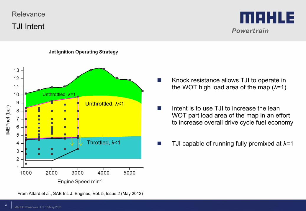
TJI Intent
Knock resistance allows TJI to operate in the WOT high load area of the map (λ=1)
Intent is to use TJI to increase the lean WOT part load area of the map in an effort to increase overall drive cycle fuel economy
TJI capable of running fully premixed at λ=1
Unthrottled, λ<1
Unthrottled, λ=1
Throttled, λ<1
From Attard et al., SAE Int. J. Engines, Vol. 5, Issue 2 (May 2012)
MAHLE Powertrain LLC, 16-May-2013

MAHLE Powertrain LLC, 16-May-2013
Relevance
5
Objectives/ACE Barriers
Objectives:
– Utilize TJI to achieve stated project goals
– Increase understanding of TJI performance sensitivity to hardware and operating conditions
Physical testing
1-D, 3-D simulation and analysis
Barriers Addressed:
– (A) Provides fundamental understanding of an advanced combustion technology
– (B) Emissions reductions may enable reduced cost emissions controls
– (C) Develop tools for modeling advanced combustion technology
– (F) Produce emissions data on an advanced combustion engine
– (G) Prioritize low cost and ease of integration
– (H) Provide comparable levels of performance to existing SI engines
MAHLE Powertrain LLC, 16-May-2013

MAHLE Powertrain LLC, 16-May-2013
Milestones Completion Date
BP1 Milestone 1 – Phase 1 Design Work Complete 07/25/12 Milestone 2 – Component Procurement Complete 10/30/12
BP2 Milestone 3 – Single-cylinder Engine Testing Complete 04/04/13 Milestone 4 – Phase 1 Research Completion 04/10/13 Milestone 5 – Boosted Single Cylinder Engine Shakedown Complete 05/16/13 Milestone 6 – Boosted Single Cylinder Engine Optimization and Vehicle Fuel Economy Prediction Complete 02/13/14
Milestone 7 – Phase 2 Complete 02/21/14 BP3
Milestone 8 – Boosted Multi-Cylinder Engine Build and Shakedown Complete 05/08/14 Milestone 9 – Boosted Engine Optimization and Vehicle Fuel Economy Prediction Complete 09/05/14
Milestone 10 – Project Complete 11/13/14
Milestones Approach
6 MAHLE Powertrain LLC, 16-May-2013
MAHLE Powertrain LLC, 16-May-2013
Approach
7
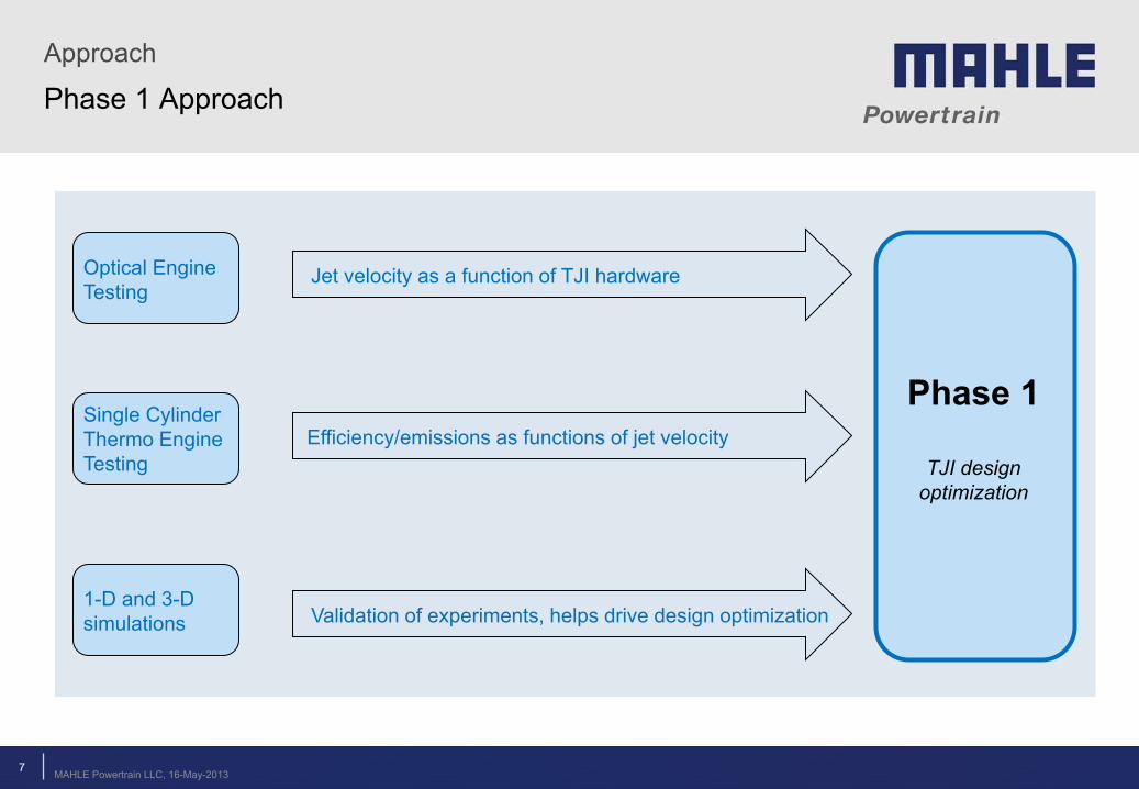
Phase 1 Approach
Jet velocity as a function of TJI hardware
Efficiency/emissions as functions of jet velocity
Validation of experiments, helps drive design optimization
Optical Engine Testing
Single Cylinder Thermo Engine Testing
1-D and 3-D simulations
Phase 1
TJI design optimization
MAHLE Powertrain LLC, 16-May-2013

MAHLE Powertrain LLC, 16-May-2013 8
Fuel injection timing/quantity and spark timing sweeps
Validation of experiments
Predict TJI vehicle drive cycle fuel economy improvement
Boosted Single Cylinder Thermo Engine Testing
1-D and 3-D simulations
1-D simulations
Phase 2
TJI design validation, operating
parameterization
Phase 3
Map generation and
drive cycle simulation
Boosted Multi-Cylinder Thermo Engine Testing
Mini-map generation provides input to 1-D simulation
MAHLE Powertrain LLC, 16-May-2013
Approach
Phases 2 and 3 Approaches

MAHLE Powertrain LLC, 16-May-2013 9
Single-cylinder optical engine successfully designed and assembled
Purpose: determine pre-chamber design effects on jet velocity, jet penetration and jet variability
Custom cylinder head
with TJI
Hydraulic assembly
Bottom end assembled
using Ford 4-cylinder
components
Optical combustion
chamber
High speed camera
High speed spectrometer
Mirror at 45 degrees
MAHLE Powertrain LLC, 16-May-2013
Technical Accomplishments
Design and Build of a Single-Cylinder Optical Engine

Technical Accomplishments
Optical Engine Data
Base TJI hardware with pre-chamber fuel injection
Operating conditions
– 1500 rpm, 3.5 bar IMEPg, λ = 1.1
Color contours show light intensity and represent cylinder temperature
Average jet velocity: ~65 m/s
TJI Nozzle
Shown: Bottom-to-top view of cylinder
MAHLE Powertrain LLC, 16-May-2013 10 MAHLE Powertrain LLC, 16-May-2013
MAHLE Powertrain LLC, 16-May-2013 11
Technical Accomplishments
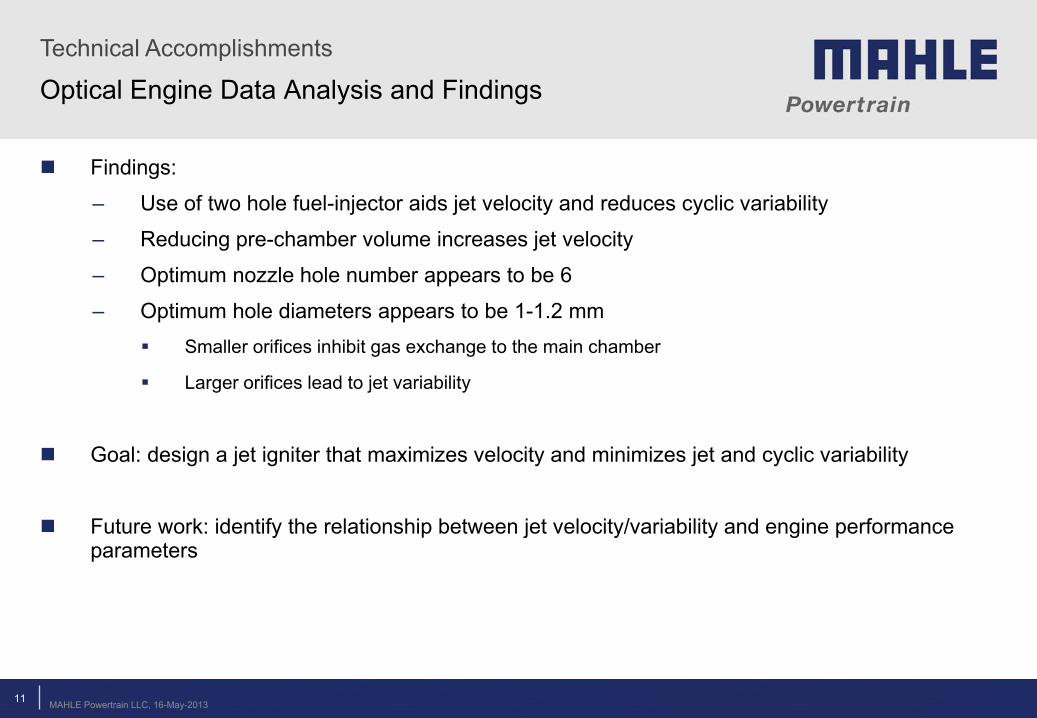
Optical Engine Data Analysis and Findings
Findings:
– Use of two hole fuel-injector aids jet velocity and reduces cyclic variability
– Reducing pre-chamber volume increases jet velocity
– Optimum nozzle hole number appears to be 6
– Optimum hole diameters appears to be 1-1.2 mm Smaller orifices inhibit gas exchange to the main chamber
Larger orifices lead to jet variability
Goal: design a jet igniter that maximizes velocity and minimizes jet and cyclic variability
Future work: identify the relationship between jet velocity/variability and engine performance parameters
MAHLE Powertrain LLC, 16-May-2013

MAHLE Powertrain LLC, 16-May-2013
Technical Accomplishments
12
Design and Build of a Single-Cylinder Engine
Single-cylinder thermodynamic (metal) engine successfully designed and assembled
– Cylinder head machined to accommodate the jet igniter assembly
– Custom crankshaft offers balanced single cylinder operation
Purpose:
– Build the metal counterpart to the optical engine
– Acquire accurate combustion, performance and emissions data
– Identify relationship between jet characteristics and engine performance
– Optimize pre-chamber design to achieve the efficiency target
TJI assembly
MAHLE Powertrain LLC, 16-May-2013

MAHLE Powertrain LLC, 16-May-2013
CFD – Insight into Flame Propagation and Jet Formation
Fluid velocity (m/s) CO2 mass fraction (-)
Spark timing: 20 CAD bTDC Burning pre-chamber charge pushes gases into the main chamber Piston motion is still upward but expanding gases overwhelm compression action Flame front forming in the main chamber before entire pre-chamber charge has been consumed Jet variability directly linked to spark plug location in the pre-chamber
Technical Accomplishments
13 MAHLE Powertrain LLC, 16-May-2013

MAHLE Powertrain LLC, 16-May-2013
CFD – Main Chamber to Pre-chamber Flow Phases
Plots show the magnitude of main chamber to pre-chamber gas exchange phases: 1 – Flow into the pre-chamber during compression 2 – Flow into the main-chamber during flame kernel development and pre-chamber burn 3 – Flow into the pre-chamber during main chamber burn 4 – Flow into the main-chamber during expansion
-40 -20 0 20 40 60 80 100 120 140-8
-6
-4
-2
0
2
4
6
8
10x 10
-3 Main chamber to pre-chamber mass flow rate vs. CAD
CAD
Mas
s Fl
ow R
ate
(kg/
s)
-40 -20 0 20 40 60 80 100 120 140 160-4
-2
0
2
4
6
8
10x 10
-6
CAD
Tota
l Mas
s Fl
ow (k
g)
Main chamber to pre-chamber total mass flow vs. CAD
1
2
3 4
1
2
3
4
Tail is not a fifth phase – just a reduction in mass flow rate
Premixed, λ=1.2
Technical Accomplishments
14 MAHLE Powertrain LLC, 16-May-2013

MAHLE Powertrain LLC, 16-May-2013
Technical Accomplishments
15
CFD – Temperature Field Visualization
Simulations performed using Converge CFD, at 1500 RPM, 2.62bar BMEP, premixed charge, λ=1.2
MAHLE Powertrain LLC, 16-May-2013

MAHLE Powertrain LLC, 16-May-2013
Collaborations and Coordination
16
Collaborations
Ford Motor Company – Project Partner
– Donated engine hardware, offered operational advice on optical engine, will participate in data sharing
Delphi Corporation – Project Subcontractor
– Supplied pre-chamber fuel injectors and are conducting CFD analysis on fuel injection characteristics
Wisconsin Engine Research Consultants – Project Subcontractor
– May perform CFD-related tasks
Spectral Energies LLC – Project Subcontractor
– Acquired optical engine images, contributed to data post-processing
MAHLE Powertrain LLC, 16-May-2013

MAHLE Powertrain LLC, 16-May-2013
Future Work
Project Timeline
Phase 1
Phase 2
Phase 3
July 2012 Design Work Complete
Aug 2012 Procurement Complete
Jan 2013 Single Cylinder
NA Testing Complete
2012 2013
2014 2015
Nov 2014 Boosted Engine
Optimization Complete
June 2014 Boosted Multi-Cylinder Engine Build Complete
Jan 2014 Boosted Single Cylinder Engine
Optimization Complete
April 2013 Boosted Single Cylinder Engine Build Complete
Single Cylinder Development and Validation Design Multi- Cylinder Development and Validation
17 MAHLE Powertrain LLC, 16-May-2013
MAHLE Powertrain LLC, 16-May-2013
Future Work
18
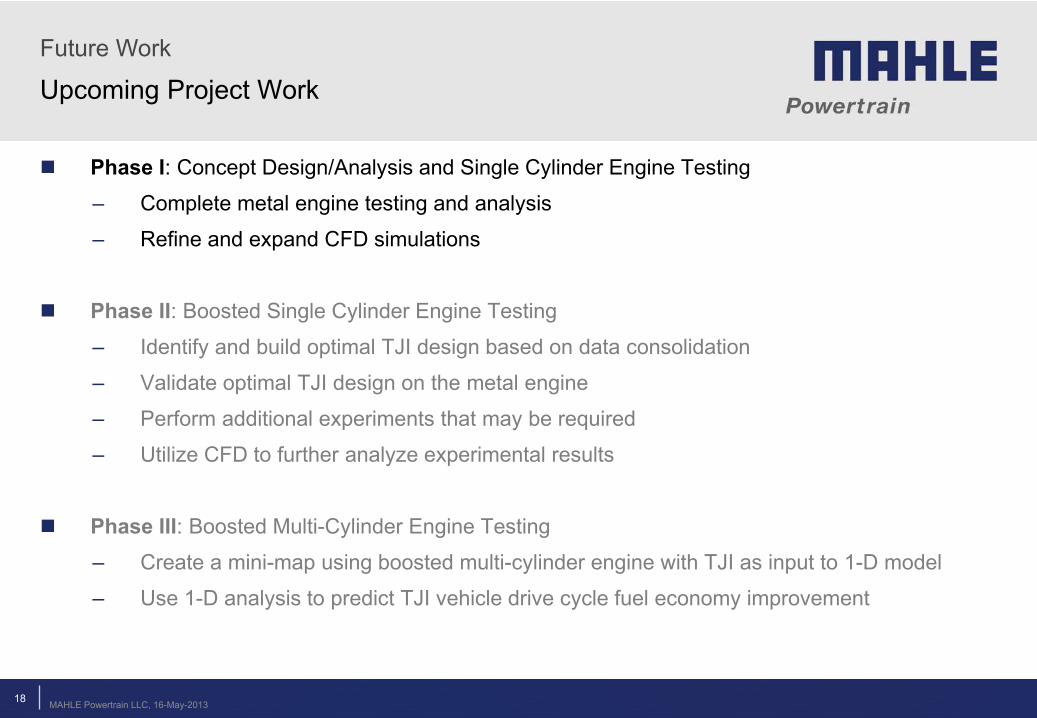
Upcoming Project Work
Phase I: Concept Design/Analysis and Single Cylinder Engine Testing
– Complete metal engine testing and analysis
– Refine and expand CFD simulations
Phase II: Boosted Single Cylinder Engine Testing
– Identify and build optimal TJI design based on data consolidation
– Validate optimal TJI design on the metal engine
– Perform additional experiments that may be required
– Utilize CFD to further analyze experimental results
Phase III: Boosted Multi-Cylinder Engine Testing
– Create a mini-map using boosted multi-cylinder engine with TJI as input to 1-D model
– Use 1-D analysis to predict TJI vehicle drive cycle fuel economy improvement
MAHLE Powertrain LLC, 16-May-2013
MAHLE Powertrain LLC, 16-May-2013 19
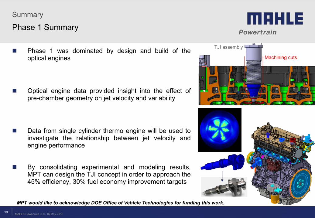
Phase 1 was dominated by design and build of the optical engines
Optical engine data provided insight into the effect of pre-chamber geometry on jet velocity and variability
Data from single cylinder thermo engine will be used to investigate the relationship between jet velocity and engine performance
By consolidating experimental and modeling results, MPT can design the TJI concept in order to approach the 45% efficiency, 30% fuel economy improvement targets
MPT would like to acknowledge DOE Office of Vehicle Technologies for funding this work.
Machining cuts
TJI assembly
MAHLE Powertrain LLC, 16-May-2013
Summary
Phase 1 Summary
Technical Back-Up Slides
20

MAHLE Powertrain LLC, 16-May-2013
Technical Accomplishments
21
Optical Engine Data Analysis
OH radical distribution from TJI into main chamber
OH* results from combustion, exists briefly in products
Relative emission intensity: 1.00
CH radical distribution from TJI into main chamber
CH* effectively describes the flame front, shorter lifespan than OH*
Relative emission intensity: 1.17
Several hardware configurations appear to effectively quench the flame from pre-chamber combustion
MAHLE Powertrain LLC, 16-May-2013