newsletternagoya-maerklin.world.coocan.jp/pdf/digital_newsletter...in the last newsletter (2015 –...
TRANSCRIPT

1
It has only been a few months since we’ve taken on the mantle of Märklin Digital Consultants. Since then, it feels like we’ve been running non-stop just to keep up. We’ve attended two show events, Eurowest (San Carlos, CA) and NMRA (Portland, OR), and we have hosted seminars on the Central Station 2. We would like to thank everyone for the support we have received from both subscribers and dealers. The correspondence we’ve received has shown a marked interest in digital operations. Please, keep the questions coming and feel free to contact us for any thoughts you have on Märklin Digital. Because there were a few months that were missed in the Digital Newsletter with the passing of Dr. Tom Catherall, we have selected topics that haven’t been covered because of updates to the system and are precursors for advanced programming. In the next few issues we should be able to start topics on basic Central Station use, and also to continue with articles of a more advanced nature.
MFX Signal Setup and Features Central Station 2 (version 4.0.1 required) With the new update (4.0.1) we can now access the CVs of the new Color Light signals (764xx) and the Semaphore signals (704xx & 703xx). The following are some instructions that will help you to get them set up in your Central Station 2 (CS2). The signal can be entered into the CS2 before or after you have installed it on your layout. It is a simple install with only red and brown wires to track power. For the semaphore signals, physical installation is up to you depending whether or not you would like the control box mounted above or below your layout. They include brackets and a template with drilling instructions included on the back page of the manual. Signal Setup The first thing that should be done is to set the address of the chip. This is because the MFX feature on the new signals is for accessing CV settings, not necessarily automatic registration of an accessory like a locomotive. Setting the address also allows the CS2 to place the signal in the desired position on the keyboard.
NEWSLETTER
Vol. 27 – No. 2 September - October 2015
Digital Consultants
Curtis Jeung Rick Sinclair

2
The signal addresses are accessible from dip switch settings are as follows: 1-256 (MM) With control unit 6021 (keyboard 6040) and Mobile Station 1 (60651/60652) 1-320 (MM) Central Station 6021x and Mobile Station 2 (60653) 1-511 (DCC) Using DCC protocol and controller Programmable addresses using the CVs: 1-2,040. Setting the Dip Switches You can see the list of addresses in the manual to get the dip switch positions, or in the CS2. Either way you have to set dip switch 10 to “off” for Märklin Motorola protocol. If you are using DCC then dip switch 10 should be set to “on”. To find the address in the CS2, enter the edit screen on the keyboard page by touching the
wrench icon . When you do activate the wrench icon, an MFX icon is now displayed next to
the “X” and “√” in the edit screen, DO NOT TOUCH THE MFX BOX AT THIS TIME!. The next step is to find an unused keyboard position and touch it. This will bring you to the accessory configuration page. Under “Decoder type” select “New installation decoder”. This will give you the dip switch positions for that address. Set the dip switches on the signal to match making sure the CS2 is set to “STOP”, there cannot be any current going to the chip while you are changing the dip switches. Remember that some signals take up two positions on the keyboard. If a position is being used, you will get a pop-up window that asks if you want to replace the accessory or re-position the new accessory (fig.1). If you have installed a new MFX signal and have had it in operation on your layout, “replace the existing accessory with new MFX item” should be selected. If you want to assign it to a different available position, you can use the drop down menu to choose a list of available positions.
Fig. 1

3
Once you have the address set, you can touch the MFX box at the lower right . The CS2 will check for new MFX chips on the system. After it has detected the chip, it will read the address that you set and you should see it on the keyboard screen in the set position. Check the green check box to exit and save the changes. Changing Keyboard Positions If you would like to move the signal to a new position on the keyboard, you can easily do this by entering the edit screen for that signal. The signal does not need to be on the programming track for this process. Then touch the desired signal to me moved. Select the drop down menu next to the address box. Then select from the available position list for the position that you would like the signal in (fig. 2). There is no need to change the dip switches. The signal will be moved to the new position once you touch the green check mark.
Fig. 2
Editing the CVs (*note – CS2 software version 4.0.1 or higher) There are a few CVs that you might want to change to set the signals to your liking. I have taken some time and adjusted some of the most common signals. I have edited the color light signal 76491, the 70392 semaphore home signal, 70381 distant signal and a 70421 yard signal. First, the signal that is to be accessed must be wired into the power leads for the programming track. There must not be any other MFX signals or trains on the programming track. Enter the edit screen on the keyboard tab then touch the signal that you want to edit. Then touch the
“CV” box . You will get a pop-up window that warns you about changing CVs and to read the manual before proceeding (always a good idea). Click on the green check mark. The CS2 will then read the CVs.

4
Once the CS2 is finished reading the CVs you will see at the bottom of the edit screen that there’s an ”Information” and a “Configuration” page, but due to a development problem, the words “Information” and “Configuration” are cut off. Select “Configuration” to access the editable CVs (fig.3).
Fig. 3
Scroll down the CV page to see the editable CVs. The text is in German so I have translations below for the CVs that might need to be changed. Color Light Signals: LED-PWM - Power Management (Dimmer) A value of 0-15 can be set. The LED is off with a value of 0 and is at it’s brightest at 15. Any number between 0-15 can be set. LED-Zeit - LED Fade Time This sets how long it takes the LED to fade out. It has four time options in seconds: 0s 0.175s 0.35s 0.5s Blended HS-Strang-Apature HS.-Strand - Switch between aspects. This sets the delay time between aspects. Gleichzeitig - Simultaneously Nacheinander - Successively Nacheinander mit 0.1s Pause - Successively with 0.1s pause Nacheinander mit 0.5s Pause - Successively with 0.5s pause

5
Semaphore Signals: LED-PWM - Power Management (Dimmer) A value of 0-15 can be set. The LED is off with a value of 0 and is at it’s brightest at 15. Any number between 0-15 can be set. Bewegungsmuster - Movement patterns Langsam - Slowly Mittel - Meduim Schnell - Fast Mittel und wippen - Medium with bouncing Schnell und wippen - Fast with bouncing Mittel und flügel 2 wippt - Medium with arm 2 bounce Mittel und flügel 1 wippt - Medium with arm 1 bounce Please note that there is no bounce with the “Slow” movement. “Medium with bouncing” will bounce the arm once at the end of each movement. “Fast with bouncing” will bounce the arm twice at the end of each movement. Enjoy your hobbies! Rick Sinclair
Wiring – Track Sensors w/ Märklin C-Track
In the last newsletter (2015 – Vol. 27 No. 1) I discussed planning strategies for automation with the primary examples using circuit tracks and contact tracks. As intended, I didn’t cover the topics of wiring nor any Central Station (CS2) setup, I wanted to stay focused on the topic of placement strategies. In this article, I will discuss the basics of Circuit Track, Reed Switches, and Contact Tracks. The wiring of these three items is established to simply set up the lead wires that get connected to the S88/L88 modules.
Circuit Track (24194 – R1 curve, 24294 – R2 curve, 24994 – straight) The Circuit Track has a center rail lever that gets pushed over when a loc’s center rail slide skids over it. It has two contact points on the underside of the track that make contact when this happens. Each contact on a Circuit Track can only be triggered by the specific direction of travel set by the slider motion. The wiring is easily accomplished by adding a spade-connected wire to the contact that is matched by the lever’s tilt. (Figs. 1, 2, 3).
Fig. 2 - Circuit track operation
Fig. 1 - Circuit track contact lever
6
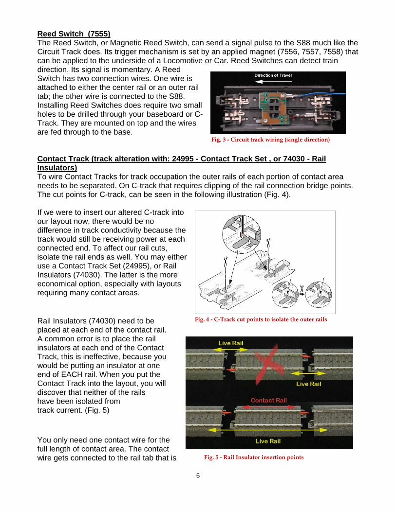
Reed Switch (7555) The Reed Switch, or Magnetic Reed Switch, can send a signal pulse to the S88 much like the Circuit Track does. Its trigger mechanism is set by an applied magnet (7556, 7557, 7558) that can be applied to the underside of a Locomotive or Car. Reed Switches can detect train direction. Its signal is momentary. A Reed Switch has two connection wires. One wire is attached to either the center rail or an outer rail tab; the other wire is connected to the S88. Installing Reed Switches does require two small holes to be drilled through your baseboard or C-Track. They are mounted on top and the wires are fed through to the base. Contact Track (track alteration with: 24995 - Contact Track Set , or 74030 - Rail Insulators) To wire Contact Tracks for track occupation the outer rails of each portion of contact area needs to be separated. On C-track that requires clipping of the rail connection bridge points. The cut points for C-track, can be seen in the following illustration (Fig. 4). If we were to insert our altered C-track into our layout now, there would be no difference in track conductivity because the track would still be receiving power at each connected end. To affect our rail cuts, isolate the rail ends as well. You may either use a Contact Track Set (24995), or Rail Insulators (74030). The latter is the more economical option, especially with layouts requiring many contact areas.
Rail Insulators (74030) need to be placed at each end of the contact rail. A common error is to place the rail insulators at each end of the Contact Track, this is ineffective, because you would be putting an insulator at one end of EACH rail. When you put the Contact Track into the layout, you will discover that neither of the rails have been isolated from track current. (Fig. 5)
You only need one contact wire for the full length of contact area. The contact wire gets connected to the rail tab that is
Fig. 4 - C-Track cut points to isolate the outer rails
Fig. 5 - Rail Insulator insertion points
Fig. 3 - Circuit track wiring (single direction)

7
nearest to the selected contact rail. In the following image, you can see the rail insulators that isolate the contact rail and the nearest tab to it. (Fig. 6)
Fig. 6 - Contact track wiring and insulation
Please note that the contact rail shown is for concept clarity. Your contact rail should, at least, be long enough in length so that the front end and back end wheels of your longest car are in contact at the same time. You do NOT need to connect a wire to each section of track within the contact area. Instead of Rail Insulators, it is possible to use Contact Track Set (24995). Contact Track Sets come in 94 mm length C-track pairs. In a single rail line, you’ll need to place one of the track pieces at each end of the Contact Track section. The pieces have blue indicators which tell you what rail is isolated. Be sure that the indicators are along the same outer rail. (Fig. 7)
Fig. 7 - Contact Track Set (24995)
The downside to using too many Contact Track Sets, is that you’ll need to accommodate for the 188mm length of straight C-track that it requires. If you require too many sets on your layout, then adapting your C-Tracks with insulators is the more economical option. In this article, I covered basic track sensors most commonly used by Märklin users. These are necessary pieces to implement any type of automation in your digital layout. They can be used exclusively or in collaborations to provide some logic based feedback control. Curtis Jeung

8
Wiring – S88 & L88 Feedback Modules (S88 - 6088, 60880, 60881, 60882 (DC); L88 - 60883) Wiring to track S88s are the connection point between your contact tracks and the Central Station 2 (CS2). The S88s are connected to each other in a chain. In the CS2, each S88 is referred to as a Module. Each Module will have 16 contact track connections. To reference a contact point it is clearer to mention the module number first, then the contact number. For examples, Module:1, Contact: 5; or Module:3, Contact 14.
The S88s have an inverted “T” icon, this is the ground connect wire. It is important to connect this input to a “live” outer rail, or the brown "O" wire connections to your layout. (Fig. 1)
Märklin has released four versions of S88s. Part numbers: 6088, 60881, 60882 (DC) and the L88 (60883). The main difference between the new and the old units are the connection ports. Older S88s (#6088 and 60880) require attachment of all contact track wires to a Märklin Plug that is appropriate for the socket version on these units. Fig. 2 shows the old S88s (Fig 2. - left side stack, 6088 on top). The plug types for the old S88s are
the yellow plugs. (Fig.2 - at bottom)
Fig. 1 - Ground connection icon
Fig. 2 - S88 comparisons: 6088 (top stack), 60880 (bottom stack), 60881 (right).

9
The newer units do not require a plug and will accept a bare wire lead directly to the green terminal connectors (Fig. 2 - right side). The other difference between the old and the new units will be how they connect to each other - and also, how they connect to the CS2. L88, S88 Connections to CS and each other. Connecting the S88/L88 to your CS gets a little more varied, because the modules are evolving into a more adaptable system. Early generations S88 (6088 & 60880) use a ribbon cable (Fig. 2- lower left) to connect to the CS2, and each other. In their packaged configuration they are meant to be placed no longer than about two feet apart (approximate length of ribbon cable). You would have to wire all of your sensor track connections around the layout and lead them to a central hub location of S88s. Available are 78 inch cable replacements, but they are not recommended if you use more than three S88s. If your layout is large and spread out, you may need long lengths of single wires running around your track. The ribbon cable connector on the CS2, is the 6-pin plug located on the underside of the CS2. New S88s have evolved into a more adaptable and convenient system. The first module of this new system is the L88. The L88 replaces the underside Central Station ribbon cable connection with a connection on the back of the CS2. You may need to purchase a terminal box (60125) if you already have boosters connected to the back of your CS2, because the L88 and 60174 boosters use the same connection port. The L88 now becomes a hub connector for any additional S88s, old and new. You can see there is a connection point for the old S88s and two connection ports for the new generation S88s. (Fig. 4 - L88 on lower right of picture). Fig. 4 - L88 and its compatibility with all S88s
Fig. 3 - S88s clustered, contacts spread out. S88 are grey boxes in middle.

10
When using an L88, do NOT use the underside ribbon connection on the CS. It is impossible to connect the new S88s directly into the old S88 setup. You must have an L88 as your first S88 type unit. The L88 has a voltage setting switch, located next to Buss 3. In Fig 4, you can see the red and blue switch to the right of the Buss 3 plug. If your system requires you to use any of the S88s plugged into Buss 3, then you must set the switch to 5 volts. (The 12 volt setting is for use with only the new CAT5 connected S88s). One advantage to using the new S88 modules are their use of CAT5 (Ethernet Cable) and RJ-45 plug ends to connect S88s. This means that you no longer have to cluster your S88s together. It allows for longer connection distances between S88s. You can have individual S88s closer to where they are needed, instead of having them all clustered together, enabling shorter runs of contact track wiring. (Fig. 5 - Contact wires in blue, S88 interconnects in grey.)
Fig. 5 - S88 localized around shorter contact track wires
The L88 requires a Switch Mode Power Supply (#66365 120 Volts / #66361 230 Volts). You may have to purchase this as a separate item. This is also the power supply that is supplied with some starter sets with a Mobile Station 2. According to Märklin instructions, connect this power supply only AFTER you have made all the connections to the L88. This article was to be a simple explanation on how to wire your S88s. However, with new models of feedback modules, the L88 and new S88, it was necessary to introduce how they differ from the older S88. I give examples on ways to place them on your layout, and the restrictions on how they interconnect. In the upcoming articles, I will start to apply what you've learned about wiring and show how to apply and utilize them in the CS2.
Curtis Jeung

11
Help with your Digital, technical and product related questions is available with just a phone call or e-mail. To contact Curtis and Rick, Märklin Digital Consultants: Phone: 650-569-1318 Hours: 6:00am – 9:00pm PST. Monday through Friday. E-mail: [email protected]
Märklin Digital Club · PO Box 510559 · New Berlin WI 53151-0559