news fireworks business - jpyro | state-of-the-art ...€¦ · page 2 entries from the encyclopedic...
TRANSCRIPT

Entries from the Encyclopedic Dictionary of Pyrotechnics that have appeared as articles Page 1
NOTE: italic terms refer additional information (found elsewhere in the text) that the reader might be inter-ested in. Those cross-referenced entries may or may not be included here.
The following entry appeared in Fireworks Business.
AERIAL SHELL APPARENT ANGULAR DIAMETER − When an object is seen at a distance, such as an aerial display shell bursting high in the air, it appears smaller than if seen at close range. This has signifi-cant ramifications for the size of shell bursts as per-ceived by spectators of a firework display. For exam-ple, consider two shell bursts, one from a small shell and one from a large shell. It is assumed that the large shell bursts with twice the spread as the small shell and that the large shell bursts at twice the altitude (illus-trated below).
For an observer directly below the shell bursts (to the left), both shells will appear to be the same size as determined by their apparent angular diameter (θ1). For an observer some distance away (right) the large shell indeed appears to have burst significantly larger than the small shell as determined by their two appar-ent angular diameters (θ2 and θ3). However, only an observer a great distance away will perceive the large shell to have twice the spread of the small shell.
When designing a firework display for a specific venue, it is important to consider the location of the primary audience and the perceived angular diame-ters of the aerial shells to be used. Thus, for a display to be discharged from a barge located a considerable distance out in a harbor with the audience on shore, large caliber shells will be well received. In contrast, for a display fired within a stadium with the audience
relatively close to the display, a larger number of smaller shells will likely be more effective than the same dollar value of larger shells.
The following entry appeared in American Fireworks News.
AERIAL SHELL BURST HEIGHT − The height of an aerial shell, above the point of firing, at the time it bursts. The results of burst height measurements from a total of 50 spherical shells ranging in size from 3 to 12 inches (70 to 300 mm) are presented below.
2 3 4 6 8 10 12200
400
600
800
1000
1200
1400
Shell Size (in.)
Bu
rst
Hei
gh
t (f
t)
Rule of ThumbFitted BurstHeight
In the above graph, the average burst height (black dot) and the extremes are shown for each size shell. A smooth curve (red) was fitted to the series of aver-age burst heights. The typical shell burst heights es-tablished for spherical shells fired at the approximate average elevation of the US (i.e., at approximately 1200 feet (365 m) above sea level) is presented below.
a) Burst height is reported to the nearest 10 feet and 5
meters.
The previous graph also includes a dashed green line, which is for a commonly used rule of thumb that states that an aerial shell bursts approximately 100 feet (30 m) in height per inch (25 mm) of shell size. While con-

Page 2 Entries from the Encyclopedic Dictionary of Pyrotechnics that have appeared as articles
venient to use, the rule-of-thumb significantly under-estimates the burst height for most spherical shells.
Salutes generally burst at lower heights than those given in the graph above. In large part this because salutes tend to weigh less than other shells of the same size (i.e., they have a lower ballistic coefficient). This results in aerodynamic drag forces having a pro-portionally greater slowing effect on salutes, thus re-ducing their vertical range compared with heavier star shells.
The following entry appeared in American Fireworks News.
AERIAL SHELL BURST SPREAD – The typical maxi-mum diameter of the display produced by an explod-ing aerial shell. The measurement of the spread of an 8-inch (200-mm) spherical shell is shown below.
The shell was suspended approximately 20 feet (6 m) above the ground. Using marker lights positioned on the ground to establish the scale, the shell was found to produce a spread of stars to approximately 810 feet (250 m).
Certainly, not all shells of a given size produce the same spread of stars. This is the result of many fac-tors including the type and amount of break charge, the strength of the shell casing and the mass and size of the stars or other shell components. However, there is good data on the maximum spread of high quality, typical, hard-breaking, spherical shells as a function of shell size. The data (Shimizu, personal communication) is from the explosion of approxi-mately 350 shells ranging from 3 to 12-inches (50 to 300 mm) from a variety of manufacturers. The burst diameter of these shells is presented below.
0
400
800
1000
600
200
1200
2 4 6 8 10 12
Shell Size (in.)
Sh
ell B
urs
t D
iam
eter
(ft
) Rule of ThumbFitted BurstDiameter
In this graph, the average burst diameter (black dot) and the extremes are shown for each size shell. A smooth curve (red) has been fitted to the average shell burst diameter over the range of shell sizes. Note that the average spread of 8 and 12-inch shells falls significantly above and below (respectively) what would be predicted from the fitted curve. The average shell burst spread (i.e., diameter) from the raw data is presented below.
a) Spread values are reported to the nearest 10 feet and
5 meters. The dashed green line in the graph is for a rule-of-thumb asserting that hard-breaking shells burst with a spread (i.e., diameter) of approximately 100 feet (30 m) per inch (25 mm) of shell size. While not providing an especially close fit to the data, the rule-of-thumb is easy to remember.
Certainly, intentionally weak-breaking spherical shells and shells of low quality will have burst spreads that are smaller than those presented above. In addition, cy-lindrical shells generally have burst spreads that are smaller than those of hard-breaking spherical shells.
The following entry appeared in Fireworks Business.

Entries from the Encyclopedic Dictionary of Pyrotechnics that have appeared as articles Page 3
AERIAL SHELL DRIFT – (Also drift effect) – Aerial shells do not follow the exact path that is predicted by simple ballistic calculations, even considering the effects of wind. This is due to bore balloting and the presence of a number of other complex-aerodynamic forces acting on the shell (e.g., Magnus force). The difference between the ballistically predicted and ac-tual trajectory of an aerial shell is described as shell drift (illustrated below).
PossibleActualPaths
Ballistically Predicted Path
MortarShell Drift
BallisticallyPredictedPoint ofFall
While it is certain there will be some amount of shell drift for each shell fired, neither the magnitude nor the direction of the drift is absolutely predictable. The magnitude of the drift will range from essentially ze-ro to at least three times the average drift. For exam-ple, approximately 10% of the spherical single-break shells fired normally will drift more than twice the average drift, and approximately 1% of such shells will drift more than three times the average drift. Fur-ther, there is no known way to predict anything about the direction of the drift. The shell can fall anywhere within a 360-degree radius of the predicted fall point.
The average drift distance for a single-break, spheri-cal shell fired normally is approximately 32 feet per inch (10 m per 25 mm) of shell size. Similarly, the average drift distance for a single-break cylindrical shell is approximately 20 feet per inch (6 m per 25 mm) of shell size. For aerial shells that burst at alti-tude as intended, there is relatively little concern for safety. In the US, shell drift is a serious safety con-cern only for those few shells that fall back to the ground as a dud shell or explode as a low break. This is because the US separation distance is 70 feet per shell inch. Thus, for single-break, spherical shells, there is a small, but non-zero, probability that some larger dud shells could fall beyond the secured boundaries of a display site.
There is a potential added effect for multibreak aerial shells that might affect the trajectory of the shell. For multibreak shells with their breaks firmly attached one to another, each time a shell break occurs, the explosive
forces produced thereby can act to redirect the course of the remaining break(s). The manner in which this might happen for a two-break shell is illustrated below.
Explosionof FirstBreak
SecondShell
Shell StartingTo Drift OffCourse
ExpectedTrajectory
TrajectoryAfter Explosion
Mortar
Double-BreakShell
In the first (upper left) illustration, the shell has just left the mortar. In the second (upper right), the shell has begun to drift off course. In the third (lower left), the first break explodes, applying a force on the re-maining second break, which causes it to deviate from the expected trajectory (lower, right).
As with single-break shell drift, the magnitude and direction of multibreak shell drift is not predictable. However, there is potential for the drift to be signifi-cantly greater than that for a single-break shell.
The following entry appeared in Peak of Flight News-letter.
BULLET EFFECT – A pyrotechnic special effect simu-lating the impact of a bullet from a weapon striking a person or an object of some type. The effect is pro-duced by a bullet hit (a small electrically initiated ex-plosive charge). Bullet effect describes both the result of functioning a properly configured bullet hit and the assemblage of materials used in producing the ef-fect.
When used on a performer: When a bullet effect is to be functioned on a performer, there must be adequate protection between the device and the person’s body. In one configuration, this can be provided in part by the use of a bullet hit shield, which also acts to direct the force of the bullet hit outward. In addition, there will be thick leather or an energy-absorbing, Sorbo-thane™ rubber layer. (The bullet hit shield and the energy-absorbing backing is generally painted red so as not to detract from the realism of the bullet effect to be produced.) An example of a bullet hit (A) in a

Page 4 Entries from the Encyclopedic Dictionary of Pyrotechnics that have appeared as articles
shield (B) with a rubber pad backing (C) is shown be-low.
To safely improve the realistic appearance of the bul-let effect, the back side of the outer layer of clothing will have been distressed by cutting slightly through the fabric with a razor blade in the area near the cen-ter of the where the bullet hit will be placed. This partial cutting of the fabric facilitates the tearing of the clothing by the bullet hit without requiring a greater level of explosive output that would more likely injure the performer wearing it. Also facilitat-ing the realism of the effect is the use of a blood bag (filled with stage blood) that has been attached to the outer layer of clothing (often using spray adhesive). Following assembly of the bullet hit effect, it is typi-cally held in place as a unit against the outer layer of clothing using gaffer’s tape. A bullet hit configured in this manner is illustrated below in cross section.
Outer Clothing Layer
Tape Layer
Protective Layer
Blood Bag
Bullet Hit Shield
Bullet Hit
Bullet HitLeg Wires
In an alternate bullet effect configuration, the bullet hit is placed between the blood bag and the outer clothing layer. In this configuration, the bullet hit shield is not used and the blood bag itself absorbs some of the explosive output of the bullet hit.
Because of the sound level produced by the explod-ing bullet hit, it is appropriate for the performer to wear hearing protection (which can be made invisible by either placing it within the ear canal or by using a well-chosen camera angle). An additional safety measure is to have the person, who is wearing the
bullet effect, actually fire the effect or at least to have an arming switch that must be activated before the ef-fect can be fired by the pyrotechnic operator.
When used on an object: In this case, a bullet effect is typically placed within an object. In one method, the object is first altered in the way that it will appear after the bullet effect has been functioned. This method is used for strong materials such as masonry or for sheet metal objects such as auto-bodies. Typi-cally, the alteration will be a combination of a dent in the object with a bullet hole formed in the center. The bullet hit will be placed into the hole, generally with its electric leads run out through the back of the ob-ject (out of view of the camera). Then, low-density plaster or clay filler material will be used to fill the hole and dent to help confine the effect of the bullet hit. Finally, the front surface of the object will made to appear undamaged by painting or other cosmetic treatment. An example of this configuration is illus-trated below in cross section.
ElectricWires
PaintedSurface
FillerMaterial
Wall
Bullet Hit
In another configuration, the bullet hit is placed with-in the object by drilling into the object from its back-side. The bullet hit is held in place using a non-hardening modeling clay (e.g., Plastilina™) or a simi-lar material. This method is best suited for objects that are less structurally strong, such as wall board (e.g., sheet rock or gypsum board) and plywood. Us-ing this method, the explosive force of the bullet hit is used to destroy the front surface of the object. An example of this configuration is illustrated below in cross section.

Entries from the Encyclopedic Dictionary of Pyrotechnics that have appeared as articles Page 5
ElectricWires
PaperCoveringWall
Board
BulletHit
ModelingClay
To properly dislodge the filler material or to destroy the front surface of the object when the bullet hit is actuated, it is common for this type of bullet hit to be significantly more powerful than could safely be used on a person. In addition, if sparks are to be produced by the bullet effect, the bullet hit may be augmented with spark-producing material such as titanium or zirconium sponge particles.
When used on in the ground: When not accom-plished pneumatically, a cork hit will be used to pro-duce the visual effect of larger scattering debris but without the potential for injury from high-density ground material (e.g., stones). A cork hit consists of a block of cork, with a relatively powerful bullet hit loaded into its center. It is placed just below the sur-face of the ground and surrounded by loose powdery material. One example of how this might be config-ured is illustrated below in cross section.
UndisturbedGround
Loose PowderyMaterial
Cork Block
Bullet Hit
Wires
An example of a cork hit block is shown below in two views; the one on the right shows the hole into which the powerful bullet hit will be loaded.
The following entry appeared in Peak of Flight News-letter.
CATALYZED PROPELLANT BURNING − Burn cata-lysts can be used to increase the burn rate of propel-lants. Metal oxides are commonly used as catalysts in model and high-power rocket motors.
The use of some lead-based catalysts often produces especially useful deviations from the burn rates pre-dicted by the Vieille equation as a function of pres-sure. The green curve (i.e., linear) in the illustration below is the relationship predicted by the Vieille equation and approximates that of a typical, non-catalyzed, double-based propellant. The red curve is typical of the pressure-dependent burn rate when us-ing lead-based catalysts such as lead salicylate or lead stearate. Typical burn rate behavior for catalyzed propellants can be divided into three regions, dis-cussed below.
Log of Pressure (p)
Lo
g o
f B
urn
ing
Rat
e (r
)
Catalyz
ed Prop
ellant
Noncatalyzed Propellant
Super-raten ~ 0.8 to 2.0
Plateaun ~ 0.0to 0.2
Mesan < 0
lnln
d rnd p
=
Illustration credit: Naminosuke Kubota
super-rate burning – A catalyzed propellant’s burning in a pressure region where its burn rate is substantially increased over its non-catalyzed rate. In this region, the burn rate pressure exponent (n) is in-creased over that for the non-catalyzed propellant.
plateau burning – A catalyzed propellant’s burn-ing in a pressure region where its burn rate is mostly pressure independent, with the burn rate pressure ex-ponent being near zero. In this region, burn rate is al-so mostly temperature independent. Accordingly, propellants (described as platonized) that are formu-lated to operate in this pressure region have especial-ly reliable performance, independent of ambient con-ditions.
mesa burning – A catalyzed propellant’s burning in a region where its burn rate decreases significantly

Page 6 Entries from the Encyclopedic Dictionary of Pyrotechnics that have appeared as articles
with increasing pressure. In this region, the burn rate pressure exponent (n) is negative.
The following entry appeared in Peak of Flight News-letter.
EJECTION BAFFLE – An assembly that eliminates the need to use disposable wadding to protect the recov-ery device of an amateur rocket. The ejection baffle works by forcing the gas from a burning ejection charge to travel through a maze-like path before reaching the recovery device. In the process, the tem-perature of the gas is reduced by its mixing with cooler air; also any large hot particles will likely be trapped within the baffle.
Often an ejection baffle is merely two or more perfo-rated disks with a separation between them (illustrat-ed below).
SecondaryBaffle
PrimaryBaffle
BodyTube
Hot EjectionGases IN
CoolerGases OUT
As an alternative, the ejection baffle may incorporate metal mesh or metal wool for additional gas cooling.
The following entry appeared in Pyrotechnics Guild International Bulletin.
FALLING LEAVES − An aerial firework effect released from an aerial firework shell that burns longer and falls much more slowly than ordinary stars. The slow rate of fall is the result of air resistance, typically from paper attached to the star composition.
One common Chinese design consists of a slow burn-ing color or sparking composition in the form of a small cylinder of densely compacted composition that is attached to a rectangular piece of paper. The color composition component resembles a small lance except that the cylinder contains no loose pow-der. The paper produces substantial air resistance and the star falls slowly like a tree leaf from a tree. Some falling-leaves shells can produce aerial displays last-ing over 20 seconds. This design is illustrated and shown below.
Heavily primed
Cylinder of starcomposition
Thin paper layer
Stiff paper
Another design for falling leaves that has been used in Japan consists of a rectangular stick of compressed star composition covered with tissue paper. The pa-per extends well beyond the end of the composition, making a tail that is approximately equal to the length of the composition (as shown below).
As the star burns, with both types of falling leaves, it loses mass. Since the star’s air resistance remains mostly unchanged, it falls progressively slower as it burns.
With both falling leaves designs, relatively little star composition is exposed to the fire of the burst charge. To assure ignition, the exposed end of the composi-tion must be heavily primed with a slurry prime.
A clever design for a miniature version of falling leaves has been used in some small Chinese consum-
Entries from the Encyclopedic Dictionary of Pyrotechnics that have appeared as articles Page 7
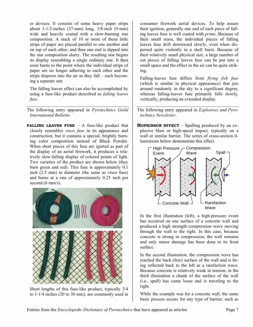
er devices. It consists of some heavy paper strips about 1-1/2-inches (37-mm) long, 3/8-inch (9-mm) wide and heavily coated with a slow-burning star composition. A stack of 10 or more of these little strips of paper are placed parallel to one another and on top of each other, and then one end is dipped into the star composition slurry. The resulting star begins its display resembling a single ordinary star. It then soon burns to the point where the individual strips of paper are no longer adhering to each other and the strips disperse into the air as they fall – each becom-ing a separate star.
The falling leaves effect can also be accomplished by using a fuse-like product described as falling leaves fuse.
The following entry appeared in Pyrotechnics Guild International Bulletin.
FALLING LEAVES FUSE – A fuse-like product that closely resembles visco fuse in its appearance and construction, but it contains a special, brightly burn-ing color composition instead of Black Powder. When short pieces of this fuse are ignited as part of the display of an aerial firework, it produces a rela-tively slow-falling display of colored points of light. Two varieties of the product are shown below (they burn green and red). This fuse is approximately 0.1 inch (2.5 mm) in diameter (the same as visco fuse) and burns at a rate of approximately 0.25 inch per second (6 mm/s).
Short lengths of this fuse-like product, typically 3/4 to 1-1/4 inches (20 to 30 mm), are commonly used in
consumer firework aerial devices. To help assure their ignition, generally one end of each piece of fall-ing leaves fuse is well coated with prime. Because of their small mass, the individual pieces of falling leaves fuse drift downward slowly, even when dis-persed quite violently in a shell burst. Because of their relatively small physical size, a large number of cut pieces of falling leaves fuse can be put into a small space and the effect in the air can be quite strik-ing.
Falling-leaves fuse differs from flying fish fuse (which is similar in physical appearance) that jets around randomly in the sky to a significant degree, whereas falling-leaves fuse primarily falls slowly, vertically, producing an extended display.
The following entry appeared in Explosives and Pyro-technics Newsletter.
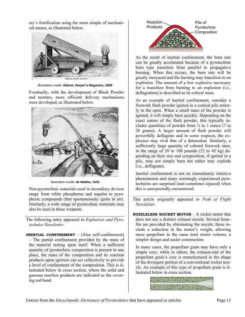
HOPKINSON EFFECT – Spalling produced by an ex-plosive blast or high-speed impact, typically on a wall or similar barrier. The series of cross-section il-lustrations below demonstrate this effect.
High PressureEvent
CompressionWave
Concrete Wall RarefactionWave
Spall
In the first illustration (left), a high-pressure event has occurred on one surface of a concrete wall and produced a high strength compression wave moving through the wall to the right. In this case, because concrete is strong in compression, the wall remains and only minor damage has been done to its front surface.
In the second illustration, the compression wave has reached the back (free) surface of the wall and is be-ing reflected back to the left as a rarefaction wave. Because concrete is relatively weak in tension, in the third illustration a chunk of the surface of the wall (i.e., spall) has come loose and is traveling to the right.
While the example was for a concrete wall, the same basic process occurs for any type of barrier, such as

Page 8 Entries from the Encyclopedic Dictionary of Pyrotechnics that have appeared as articles
armor plating, with the potential for similar results. The Hopkinson effect is used for some types of anti-tank weapons.
(Note that this is not the same Hopkinson effect that is associated with magnetics; however, it is the effect operating in the Hopkinson pressure bar test.)
The following entry appeared in Explosives and Pyro-technics Newsletter.
HOPKINSON PRESSURE BAR TEST – The quantita-tive measurement of the pressure developed by a high explosive over a small interval of time, which is a measure of its explosive violence. The principle on which the determination of pressure is based depends on the Hopkinson effect. Specifically, that when an explosive charge is fired in contact with the end of a ballistically suspended, cylindrical steel bar, a wave of compression travels along the bar and is reflected at the far end as a rarefaction or tension wave.
To investigate the properties of the compression wave, first a short length of bar farthest from the charge is cut off. (This short segment is known as the timepiece.) The ends of both bars are smoothly sur-faced, and the two pieces are joined using only a film of petroleum jelly (e.g., Vaseline). While a compres-sion wave travels unchanged through the joint going into the timepiece, the film is unable to transmit the reflected tension wave. Hence, when the amplitude of the reflected tension wave reaching the joint becomes greater than that of the original compression wave, the timepiece is projected with a momentum that de-pends on the explosive pressure developed and the time for the pressure wave to traverse the length of the timepiece.
By using a number of timepieces of different lengths, it is possible to approximate the maximum pressure developed and to calculate average pressure values over various time intervals.
To protect the Hopkinson pressure bar instrument, it is necessary to interpose a fresh pellet of standardized material between the test explosive and the pressure bar for each test.
The following entry appeared in Pyrotechnics Guild International Bulletin.
IGNITER CORD – A thin, flexible, externally hot-burning fuse, usually having a diameter of approxi-mately 3/32 inch (2.4 mm). It is typically extruded and may be covered with a sparse wrap of thin wires
and/or thread, or it may have a continuous thin plastic jacket. Typically, its powder core is thought to con-sist of a mixture of lead(II,II,IV) oxide and silicon with a nitrocellulose binder; some igniter cord com-positions also contain potassium perchlorate. Thus, igniter cord composition burns much hotter than a typical Black Powder-type fuse.
The appearance of a range of different igniter cords is shown below.
Igniter cord 1 is of German origin (Wasag Chemie); 2 is two types of Ensign Bickford’s (EB) quarry cord (Q-Cord); 3 is Mantitor plastic igniter cord (PIC) from Brazil (Orica Brazil); 4 is three types of igniter cord from Imperial Chemical Industries (ICI) from the UK; and 5 is three types of Thermalite (CXA, Ltd., Canada). (Some of these products are discussed further, below.)
While igniter cord has several uses in fireworks and rocketry, it is primarily manufactured for use in com-mercial blasting operations, where it is used in con-junction with blasting safety fuse. Since the use of blasting safety fuse has almost totally been replaced with more modern initiation methods (e.g., detonating cord and shock tube), many igniter-cord products have ceased to be manufactured; however, even some of the discontinued cords are still available in limited quantity.
The burn rate of the various igniter cords covers a wide range, which can be useful for a variety of pyrotechnic applications. The approximate burn rates of some ig-niter cords are presented below.

Entries from the Encyclopedic Dictionary of Pyrotechnics that have appeared as articles Page 9
a) Values to the nearest 0.1 in./s (5 mm/s) or 2 significant
figures. b) Values to the nearest 0.01 s/in. (0.1 s/mm) or 2 signifi-
cant figures. c) This newer of the two Ensign-Bickford products, which
reportedly uses a lead(II,II,IV) oxide, silicon and potas-sium perchlorate fuse powder, is more susceptible to accidental ignition.
d) This older of the two Ensign-Bickford products used a Black Powder-based fuse powder.
Safety note: Igniter cords have varying degrees of sen-sitiveness to accidental ignition. When cutting any ig-niter cord (as with cutting any fuse material) consid-eration must be given to the possibility of its ignition.
In fireworks: Igniter cord is sometimes used in a type of chain fusing that burns slower than quick match. An example of this use is shown below.
In the above example, the quick match leader fuse from five aerial shells has been taped to the igniter cord (red arrow) at five points along its length (yel-low circles). Following this, the fusing will be cov-ered with tape to provide a degree of resistance to ac-cidental ignition from burning fallout.
In rocketry: In high-power rocketry, a type of rocket motor igniter is sometimes fabricated from a camera flashbulb and a length of fast (white) Thermalite ig-niter cord made into a type of quick match by insert-ing it into a thin plastic tube (as shown below). This
type of igniter has the advantage of being able to be extended into the top of the rocket motor core where the ignition of composite propellants properly occurs.
In blasting: Blasting safety fuse can be quite difficult to ignite using the flame from a match or cigarette lighter; this can pose a problem when several fuses need to be ignited at about the same time. Igniter cord is readily ignited, and it can be used to easily and near simultaneously ignite a collection of two or more lengths of blasting safety fuse. This can be ac-complished using igniter-cord connectors or simply by punching a hole through the fuse and stringing ig-niter cord through the holes, as shown below (the size of the grid is 0.1 inch).
Quarry Cord™ – The name for an igniter cord formerly manufactured by Ensign Bickford. Over the period of its manufacture, the fuse used two distinctly different powders, with significantly different burn rates, but they looked similar (see below).
The upper type of fuse is from earlier production, which contained a Black Powder-type composition (with a burn rate of 3.4 inches, 85 mm, per second) and was relatively insensitive to accidental ignition. The lower type of fuse is from later production and contains a Goldschmidt reaction composition, appar-ently based on lead(II,II,IV) oxide, silicon and potas-sium perchlorate. This fuse (with a burn rate of 48

Page 10 Entries from the Encyclopedic Dictionary of Pyrotechnics that have appeared as articles
inches, 1.2 m, per second) was more sensitive and could be ignited by the sharp blow of a hammer on a hard surface; it carried a warning on its rolls (shown on the left below). Both types of fuse were supplied on 500-foot (150-m) spools.
Mantitor™ cord – (Also plastic igniter cord, ab-breviated as PIC) – The trade name for a plastic ig-niter cord now manufactured by Orica Brazil. It is made with a composition extruded around a thin cop-per wire. It also has an external iron wire for added strength and is covered with a layer of plastic. An ex-ample of the construction of Mantitor igniter cord is illustrated below.
Outer Wire (Iron)
Plastic Coating
Powder CoreCore Wire (Copper)
Mantitor cord burns approximately 0.8 inch per sec-ond (20 mm/s) with a hot, external flame. It is the most commonly available igniter cord in the US and is supplied on a 100 m (330 foot) black plastic spool, as shown below.
ICI plastic igniter cord – A plastic-covered ignit-er cord formerly manufactured by Imperial Chemical Industries in Scotland. The slower speed(s) of this fuse came in various-colored plastic outer wraps that had similar (or identical) burn rates, approximately 0.9 inch per second (22 mm/s). These ICI cords were
constructed much like the more recently produced Mantitor cord, with a copper wire at its core and an iron wire for strength. The fast speed ICI plastic ig-niter cord (brown) was slightly thicker and was man-ufactured with a number of fibrous threads in its core as opposed to a wire. This fuse burned quite fast, ap-proximately 12 inches per second (300 mm/s). Each type of ICI cord was supplied on a 150 m (500 foot) chipboard spool, as shown below.
The faster burn rate of ICI plastic igniter cord result-ed in it sometimes being used as a quick match sub-stitute for lancework. This fuse was an effective al-ternative when it was desired to have a lancework ig-nite at a slower and less frenetic pace than results from using quick match.
Thermalite™ fuse – The trade name for an igniter cord formerly manufactured by CXA, Ltd. It appar-ently was made with a composition containing lead(II,II,IV) oxide, silicon and nitrocellulose that was extruded around a thin copper wire; it then had iron wires and a sparse wrap of threads wound around its outside. It burned with a hot, external flame. An example of the construction of Thermalite igniter cord is illustrated below.
Outer Wires (Iron)
Powder Core
Core Wire (Copper)Fine Thread Wrap
Thermalite was available in three color-coded speeds supplied in 30 m (100 foot) rolls wound on a red plastic spools (shown below). The red fuse burned slowest, green was an intermediate speed and white was fastest (see the above table for burn rates).

Entries from the Encyclopedic Dictionary of Pyrotechnics that have appeared as articles Page 11
In fireworks: On occasion, Thermalite was used as the cross-matching fuse for Bickford-style time fuse. However, the reliability of this practice was problem-atic because of the tendency for its outer wires to rust over time, contributing to the fuse’s resistance to side ignition. Thermalite was also used quite successfully to make timing bars for use in slow-firing fuse chains.
In rocketry: Thermalite is sometimes used to ignite composite rocket motors (discussed above).
The following entry appeared in Explosives and Pyro-technics Newsletter.
IGNITION PROPAGATION ENERGY DIAGRAM – This is an aid used to visualize the relationship between ignition stimulus, activation energy and the enthalpy of reaction for one or a series of connected pyrotech-nic compositions. The value of these diagrams lies in their ability to provide a qualitative understanding of a number of ignition and propagation problems, and how these problems may be overcome. An ignition propagation energy diagram is a clever combination of a sketch and a qualitative graph, as illustrated be-low.
En e
rgy
Ea
Ef
a'
b'b
a
Present Burning Surface
Initial Burning Surface
}
}Sketch
Graph
Is
The lower portion of the Shimizu diagram is simply a sketch of a portion of some pyrotechnic composition, shown as initially having a burning surface a-b, and which has burned to the current burning surface a’-b’. Above the sketch is a graph of energy as a function of distance along the composition. Here, the two key terms from the propagation inequality are charted. The energy being fed back from the presently react-ing layer of composition to the next (pre-reacting) layer just behind it (Ef) is shown as a dashed, orange line. Also charted is the activation energy (Ea) re-quired for ignition and for the composition to main-tain burning, which is shown as a solid, blue line.
When the process of ignition is discussed, the amount of energy (ignition stimulus) being delivered to the exposed surface of the composition can be shown as an arrow (red) from the left side of the diagram (Is). The source of the ignition stimulus can take any of several forms. It could be direct thermal energy, such as provided by a burning fuse. However, it could also be thermal energy derived from a mechanical stimu-lus (i.e., from impact or friction), or an electrical stimulus (i.e., from an electrostatic discharge).
In simplest terms, the ignition of the composition will be successful only if the ignition stimulus (Is) exceeds the composition’s activation energy (Ea) requirement. Further, propagation will continue only so long as the amount of energy being fed back (Ef) is greater than the activation energy requirement. Both of these re-quirements are met in the above example; according-ly, this pyrotechnic composition will be ignited by the ignition stimulus and it will propagate throughout its length. Two more examples will help demonstrate the utility of Shimizu diagrams.
In the first example, an attempt is being made to ig-nite a pyrotechnic composition with a fixed level of ignition stimulus. Note first, in the illustration below, that this pyrotechnic composition will propagate once it is ignited because the amount of energy it will feed back (Ef) is greater than its activation energy re-quirement (Ea). However, the first attempt to ignite the composition directly is unsuccessful because the level of the ignition stimulus (Is) is below the compo-sition’s activation energy requirement.

Page 12 Entries from the Encyclopedic Dictionary of Pyrotechnics that have appeared as articles
Ef
Ea
Pyro. Comp.
Is
The difficulty with ignition of this composition can be corrected by first applying a layer of suitable prime composition on the surface to be ignited as il-lustrated below.
Efp
Eap
Prime
EfE
a
Is
Pyro. Comp.
The ignition of the prime is now successful because the level of the ignition stimulus for the prime is greater than the activation energy requirement for the prime composition (Eap) and the prime will burn be-cause the energy it feeds back is greater than its acti-vation energy requirement. Once the burning prime proceeds to the right and meets the main pyrotechnic composition, the prime will successfully ignite that composition because the energy fed back from the prime (Efp) is also greater than the activation energy requirement of the composition (Ea). (The thickness of the prime layer has been exaggerated for clarity.)
An example of an ignition propagation energy dia-gram for a pair of pyrotechnic compositions in con-tact with each other, such as would be found in a col-or-changing star is shown below. Note that each of the two compositions will propagate if successfully ignited (i.e., in each case the burning composition will feed back more energy than is needed for its ac-tivation energy). In this case, the real question is whether, once ignited, the outer composition (Comp. 2) will successfully ignite the inner composition (Comp. 1). Clearly, in this case it will not, because the inner composition requires greater activation en-ergy (Ea1) than is being fed back by the outer burning composition (Ef2)
Ea1E
f2
Comp. 2 Comp. 1
The failure to have the outer composition successful-ly ignite the inner composition can be overcome by the interposition of a suitable layer of prime composi-tion, as shown below. (The thickness of the prime layer has been exaggerated for clarity.)
Eap
Efp
Prime
Ef2
Ea1
Comp. 1Comp. 2
In this case, once the burning has proceeded to the right to reach the interface with the prime, since the energy fed back by the outer composition (Ef2) is greater than the activation energy requirement of the prime (Eap), it will be ignited. In this case, since the energy fed back by the now burning prime composi-tion (Efp) is greater than the activation energy re-quired by the inner composition (Ea1), it will be ignit-ed by the prime.
The following entry appeared in Explosives and Pyro-technics Newsletter.
INCENDIARY DEVICE or BOMB – This is a device for use as a weapon that, when functioned, produces in-tense heat of long duration and is intended to start or promote a substantial fire. This is accomplished ei-ther by the production of a persistent flame or hot particles (such as molten metal produced by thermite or other Goldschmidt reaction compositions). As such, an incendiary device may cause severe injury or casualties if their combustion products come in con-tact with the human body.
Incendiary devices have been used in warfare for many centuries, with Greek fire being one of the first effective weapons of this type. In the earliest times, these weapons were sometimes delivered to an ene-
Entries from the Encyclopedic Dictionary of Pyrotechnics that have appeared as articles Page 13
my’s fortification using the most simple of mechani-cal means, as illustrated below.
Illustration credit: Abbott, Harper’s Magazine, 1869
Eventually, with the development of Black Powder and mortars, more efficient delivery mechanisms were developed, as illustrated below.
Illustration credit: de Malthe, 1633
Non-pyrotechnic materials used in incendiary devices range from white phosphorus and napalm to pyro-phoric compounds (that spontaneously ignite in air). Similarly, a wide range of pyrotechnic materials may also be used in these weapons.
The following entry appeared in Explosives and Pyro-technics Newsletter.
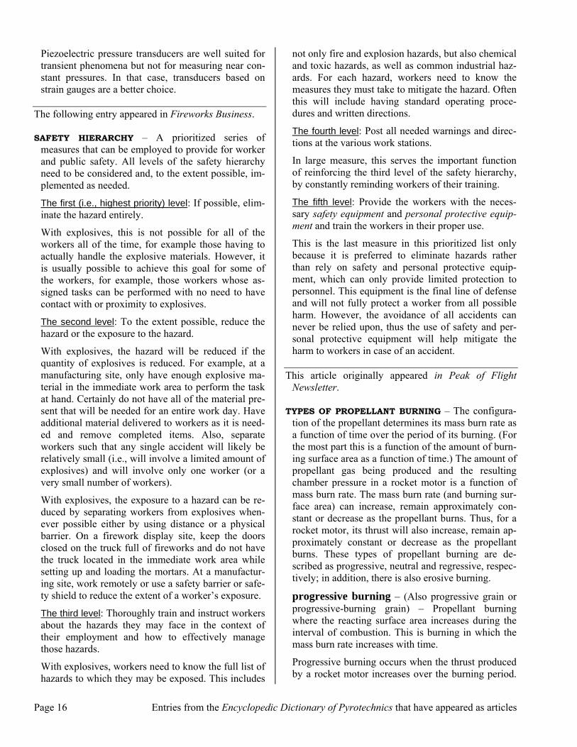
INERTIAL CONFINEMENT – (Also self-confinement) – The partial confinement provided by the mass of the material resting upon itself. When a sufficient quantity of pyrotechnic composition is present in one place, the mass of the composition and its reaction products upon ignition can act collectively to provide a level of confinement of the composition. This is il-lustrated below in cross section, where the solid and gaseous reaction products are indicated as the cover-ing red band.
ReactionProducts
Pile ofPyrotechnicComposition
As the result of inertial confinement, the burn rate can be greatly accelerated because of a pyrotechnic burn type transition from parallel to propagative burning. When this occurs, the burn rate will be greatly increased and the burning may transition to an explosion. The amount of a low explosive necessary for a transition from burning to an explosion (i.e., deflagration) is described as its critical mass.
As an example of inertial confinement, consider a firework flash powder ignited in a conical pile entire-ly in the open. When a small mass of the powder is ignited, it will simply burn quickly. Depending on the exact nature of the flash powder, this typically in-cludes quantities of powder from ¼ to 1 ounce (7 to 28 grams). A larger amount of flash powder will powerfully deflagrate and in some respects, the ex-plosion may rival that of a detonation. Similarly, a sufficiently large quantity of colored firework stars, in the range of 50 to 100 pounds (22 to 45 kg) de-pending on their size and composition, if ignited in a pile, may not simply burn but rather may explode (i.e., deflagrate).
Inertial confinement is not an immediately intuitive phenomenon and many seemingly experienced pyro-technists are surprised (and sometimes injured) when this is unexpectedly encountered.
This article originally appeared in Peak of Flight Newsletter.
NOZZLELESS ROCKET MOTOR – A rocket motor that does not use a distinct exhaust nozzle. Several bene-fits are provided by eliminating the nozzle; these in-clude a reduction in the motor’s weight, allowing more propellant in the same total motor volume, a simpler design and easier construction.
In many cases, the propellant grain may have only a simple core; while in others, the exhaust-end of the propellant grain’s core is manufactured in the shape of the divergent portion of a conventional rocket noz-zle. An example of this type of propellant grain is il-lustrated below in cross section.

Page 14 Entries from the Encyclopedic Dictionary of Pyrotechnics that have appeared as articles
With careful design, a nearly constant thrust profile can be achieved. However, there are also disad-vantages. The thrust coefficient and specific impulse (Isp) obtained from a nozzleless rocket will not be as high as that for a rocket motor with a conventional convergent-divergent nozzle. The Isp may be only approximately 80% that of a well-designed motor having a nozzle.
While simpler in design, it requires care in ensuring that the design provides critical flow at the exit plane without producing excessively high head-end pres-sures. An interesting variation of the nozzleless mo-tor is the use of a nozzle made of another propellant that burns out at the same time as the main propel-lant.
A nozzleless rocket motor may be used as the booster motor of an integrated rocket ramjet or ducted rocket motor. In this case, the nozzleless rocket motor occu-pies what will be the ramburner. This is a simplifica-tion because the booster rocket motor and/or nozzle do not need to be ejected once it has completed its function. How this might be configured is illustrated below in cross section.
Gas Generating Pyrolant Air Intake
Booster Propellant Grain
Illustration credit: Naminosuke Kubota
The following entry appeared in Explosives and Pyro-technics Newsletter.
ROCKET MOTOR MOUNT – Construction used to po-sition and hold a rocket motor securely in the rocket body (i.e., airframe). The simplest form of a motor mount may be little more than the rocket’s body tube itself; in contrast, for a rocket using a cluster of mo-tors, the motor mount may be quite complex.
Typically, a model rocket motor mount will consist of a motor mount tube with a motor hook, possibly with spacers and a motor block. A completed model rocket motor mount is shown below (upper) and then with the motor mount (with a motor inserted) in-stalled into the lower-finned section of a model rock-et (lower).
High-power rocket motors often require more sub-stantial methods of motor retention.
motor mount tube – (Also engine tube) – A tube whose inside diameter is only very slightly larger than the rocket motor’s outside diameter. A small rocket motor (A) having been installed into its motor mount tube (B) is shown below.
motor hook – (Also engine hook) – Typically a flat piece of metal bent at both ends to hold the rocket motor in position once it has been inserted into the motor mount tube. An example of a motor hook (C) alongside the rocket motor (A) for which it is intend-ed is shown below.
The bottom end of the motor hook (C1) prevents the motor (A) from slipping out before launch or its being ejected rearward when the ejection charge ignites (and yet allows the easy insertion and removal of the motor before and after the rocket’s flight). The top end of the motor hook (C2) prevents the motor from slipping up into the rocket’s body tube as the motor functions. For more powerful motors, a motor block may be used and may also back up the top end of the motor hook for extra strength, even with smaller mo-tors.

Entries from the Encyclopedic Dictionary of Pyrotechnics that have appeared as articles Page 15
motor block – (Also engine block) – A thick-walled, short tube or bulkhead used to couple the rocket motor’s thrust to the rocket’s airframe. The motor block is firmly attached to the body tube of the rocket just ahead of the motor. As the motor func-tions, it presses against the motor block, transferring its force to the body of the rocket. When the motor has an ejection charge, used to deploy a recovery de-vice, it is necessary that the motor block be designed to allow the ejection charge gases to pass through it. The motor block may be combined with an ejection baffle as a single unit.
motor-mount centering ring – (Also motor-mount adapter) – A device (often a short thick-walled tube) used to fill the gap between the outside diame-ter of the motor-mount tube and the inside diameter of the rocket’s body tube. The two centering rings (D) for the assembled motor mount, and the securing band for the motor hook (E), are shown below.
This article originally appeared in Peak of Flight Newsletter.
PRESSURE TRANSDUCER – An instrument that pro-duces an output (typically electrical) resulting from (and usually proportional to) an imparted pressure. Some simple pressure gauges may qualify as exam-ples of pressure transducers. Such gauges do not, however, usually provide a record of the pressures, and they have a relatively slow response time. These shortcomings make these gauges unsuitable for many applications in pyrotechnics. For example, a pressure profile (pressure vs. time) of the blast pressure wave produced by an explosion is presented below. This event occurred over a time span of less than one mil-lisecond.
For such a short duration event, it is necessary to produce automatically recorded results from an in-strument with an extremely fast response time. Pie-zoelectric transducers for pressure measurement are well suited for such applications. The transducer (a free-field blast gauge) used to record the above pres-sure profile is shown below. (The numerical data was recorded by a digital oscilloscope.)
The unit is used by pointing it at the source of the blast (the red arrow is pointing to the actual piezoe-lectric pressure transducer mounted into the side of the unit).
Examples of piezoelectric pressure transducers that are used more like a conventional dial pressure gauge are shown below. The upper gauge reads to 100 psi (689 kPa), while the lower gauge reads to 100,000 psi (689 MPa). For both transducers, the electrical con-nection is on the left end and the pressure is sensed at the end to right.
As part of a study of various proximate-audience concussion powders, the pressures produced inside standard concussion mortars were measured using the high pressure transducer shown above. In a few trials, extremely short duration and extremely high pressure events were recorded. In the example presented be-low, the spike had a duration of less than 50 micro-seconds during which the pressure rose to nearly 100,000 psi (690 MPa).
0
30000
60000
90000
Pre
ssu
r e (
psi
)
0.0 0.5 1.0 1.5 2.0Time (ms)
Page 16 Entries from the Encyclopedic Dictionary of Pyrotechnics that have appeared as articles
Piezoelectric pressure transducers are well suited for transient phenomena but not for measuring near con-stant pressures. In that case, transducers based on strain gauges are a better choice.
The following entry appeared in Fireworks Business.
SAFETY HIERARCHY – A prioritized series of measures that can be employed to provide for worker and public safety. All levels of the safety hierarchy need to be considered and, to the extent possible, im-plemented as needed.
The first (i.e., highest priority) level: If possible, elim-inate the hazard entirely.
With explosives, this is not possible for all of the workers all of the time, for example those having to actually handle the explosive materials. However, it is usually possible to achieve this goal for some of the workers, for example, those workers whose as-signed tasks can be performed with no need to have contact with or proximity to explosives.
The second level: To the extent possible, reduce the hazard or the exposure to the hazard.
With explosives, the hazard will be reduced if the quantity of explosives is reduced. For example, at a manufacturing site, only have enough explosive ma-terial in the immediate work area to perform the task at hand. Certainly do not have all of the material pre-sent that will be needed for an entire work day. Have additional material delivered to workers as it is need-ed and remove completed items. Also, separate workers such that any single accident will likely be relatively small (i.e., will involve a limited amount of explosives) and will involve only one worker (or a very small number of workers).
With explosives, the exposure to a hazard can be re-duced by separating workers from explosives when-ever possible either by using distance or a physical barrier. On a firework display site, keep the doors closed on the truck full of fireworks and do not have the truck located in the immediate work area while setting up and loading the mortars. At a manufactur-ing site, work remotely or use a safety barrier or safe-ty shield to reduce the extent of a worker’s exposure.
The third level: Thoroughly train and instruct workers about the hazards they may face in the context of their employment and how to effectively manage those hazards.
With explosives, workers need to know the full list of hazards to which they may be exposed. This includes
not only fire and explosion hazards, but also chemical and toxic hazards, as well as common industrial haz-ards. For each hazard, workers need to know the measures they must take to mitigate the hazard. Often this will include having standard operating proce-dures and written directions.
The fourth level: Post all needed warnings and direc-tions at the various work stations.
In large measure, this serves the important function of reinforcing the third level of the safety hierarchy, by constantly reminding workers of their training.
The fifth level: Provide the workers with the neces-sary safety equipment and personal protective equip-ment and train the workers in their proper use.
This is the last measure in this prioritized list only because it is preferred to eliminate hazards rather than rely on safety and personal protective equip-ment, which can only provide limited protection to personnel. This equipment is the final line of defense and will not fully protect a worker from all possible harm. However, the avoidance of all accidents can never be relied upon, thus the use of safety and per-sonal protective equipment will help mitigate the harm to workers in case of an accident.
This article originally appeared in Peak of Flight Newsletter.
TYPES OF PROPELLANT BURNING – The configura-tion of the propellant determines its mass burn rate as a function of time over the period of its burning. (For the most part this is a function of the amount of burn-ing surface area as a function of time.) The amount of propellant gas being produced and the resulting chamber pressure in a rocket motor is a function of mass burn rate. The mass burn rate (and burning sur-face area) can increase, remain approximately con-stant or decrease as the propellant burns. Thus, for a rocket motor, its thrust will also increase, remain ap-proximately constant or decrease as the propellant burns. These types of propellant burning are de-scribed as progressive, neutral and regressive, respec-tively; in addition, there is also erosive burning.
progressive burning – (Also progressive grain or progressive-burning grain) – Propellant burning where the reacting surface area increases during the interval of combustion. This is burning in which the mass burn rate increases with time.
Progressive burning occurs when the thrust produced by a rocket motor increases over the burning period.

Entries from the Encyclopedic Dictionary of Pyrotechnics that have appeared as articles Page 17
A simple configuration that exhibits progressive burning is a case-bonded grain with a cylindrical core. As burning proceeds, the diameter of the core increases, causing the burning surface area to in-crease, resulting in increased gas production and thrust. One example of a progressive-burning grain is illustrated below. This is a typical thrust profile for a rocket motor with a BATES grain in which the indi-vidual grain segments are relatively long.
Th
rust
Time
BATES - Progressive
neutral burning – (Also neutral grain or neutral-burning grain) – Propellant burning where the react-ing surface area remains approximately constant dur-ing the interval of combustion. In this type of burn-ing, the mass burn rate remains approximately con-stant over time.
Neutral burning occurs when the thrust produced is approximately constant over the burning period. Many propellant grain geometries can be configured to approximate neutral burning. The thrust profile for a simple, end-burning propellant grain is illustrated below, where the slight increase in thrust (typically a temperature effect) is ignored.
Time
Th
rust
End Burning
regressive burning – (Also degressive burning, re-gressive-propellant grain or regressive-burning grain) – Propellant burning where the reacting surface area decreases during the interval of combustion. In this type of burning, the mass burn rate decreases with time.
Regressive burning occurs when the thrust produced by a rocket motor decreases over the burning period. A regressive-burning grain shape is such that the total amount of burning surface area decreases as burning continues. An example of a configuration that has re-gressive burning is illustrated below. This is a typical
thrust profile for a motor with a BATES grain in which the individual grain segments are relatively short.
Th
rust
Time
BATES - Regressive
erosive burning – Propellant burning in which the normal burn rate is augmented or increased by high velocity gas moving past or directed against a burn-ing surface. (There are other theories attempting to explain erosive burning, but this seems to be the sim-plest explanation for a first approximation.)
Erosive burning is a burning mode caused by en-hanced thermal energy feedback when burning sur-faces are in close proximity. Erosive burning can be caused by having a core diameter close to that of the nozzle diameter (i.e., a low port-to-throat ratio). Ero-sive burning can produce sonic or near sonic gas ve-locities and shock waves within the propellant core. Motor designers generally avoid erosive burning, but it can be used to increase the initial thrust for a so-called hot start. This manifests itself as the ignition spike often seen in model rocket motors. An example of this is illustrated below in the thrust profile of a core-burning motor.
Time
Th
rust
Ignition Spike
A severe type of erosive burning may occur because of physical properties of the grain. Propellants with poor physical properties may have chunks of propel-lant literally torn out of the grain surface and exposed to gas flow. These propellants should not be used in rocket motors because their performance is very dif-ficult to control or predict.
The following entry appeared in Explosives and Pyro-technics Newsletter.
VIEILLE EQUATION – (Also Vieille’s law, St. Rob-ert’s law or burn rate equation) – This was initially

Page 18 Entries from the Encyclopedic Dictionary of Pyrotechnics that have appeared as articles
proposed by Paul Vieille (1854–1934), a French chemist and the inventor of a smokeless powder. The Vieille equation states that the linear burn rate (r) of a pyrotechnic material or propellant, at constant tem-perature, is equal to some power (n) of local pressure (P) times a constant (a):
nr a P= ⋅
Here, a and n are constants that depend on the nature of the pyrotechnic material. Further, n is sometimes described as the pressure exponent and a as the pres-sure coefficient (discussed below). Accordingly, the pressure exponent is the slope of the burn rate curve when burn rate is plotted against pressure in a log-log format.
For Black Powder, with the burn rate in mm/s and a pressure in atmospheres, a = 12.1 and n = 0.24 (Shid-lovskiy, 1964). This relationship is presented below.
Pressure (atm)1 10 100
Bu
rn R
ate
(mm
/s)
10
50
For some pyrotechnic compositions, this relationship holds over a wide range of pressures, but for others, it only applies over limited pressure ranges (i.e., the constants are not truly constant).
The Vieille constants for compressed pellets of some other compositions are presented below (Shimizu, 1981), where burn rate (a) is in mm/s and pressure (P) is in atmospheres.
The mechanism through which burn rate increases as a function of increased ambient pressure is by in-creasing the efficiency of thermal energy feedback. With increasing pressure, any flame produced will shrink in size to become a more concentrated source of radiated thermal energy, and it will be held closer to the burning surface. The effect of greater thermal energy feedback is to decrease the time taken for each successive thin layer of composition, in a larger block of composition, to be raised to its ignition tem-
perature. The result of taking less time is an increase in burn rate.
An example of the effect of increased pressure on a flame is shown below for a double-base, smokeless propellant. The flames are burning under pressures of 1, 2 and 3 MPa (approximately 150, 300 and 450 psi), from left to right, respectively.
Photo credit: Naminosuke Kubota
Many seemingly slow-burning compositions become fast burning when strongly encased. Smokeless pow-ders (i.e., nitrocellulose-based propellants) are espe-cially good examples of the importance of the pres-sure exponent on burning behavior. A small trail of smokeless powder, such as used in small-arms am-munition, burns fairly slowly in the open. However when the same powder is ignited in the confined space of a weapon, it burns almost instantaneously.
In rocketry: The Vieille equation constants (a and n) play a central role in determining chamber pressure (Pc):
1111* nn
n nc
d
a C K a KPg g c
ρ ρ −− ⋅ ⋅ ⋅ ⋅ ⋅= = ⋅
Here, ρ is the density of the propellant (in lb/cu.in.), Kn is the ratio of the burning surface area to the cross-sectional area of the nozzle, g is the gravitational constant (32.2 ft/s2), C* is the characteristic exhaust velocity (in ft/s), and cd (in s/ft) is the discharge coef-ficient of the nozzle (a function of the temperature and composition of the combustion products). Note that cd is equal to 1/C*.
pressure exponent – (Also burn-rate pressure sen-sitivity or combustion index) – The exponent (n) placed on the pressure term in the Vieille equation can be determined experimentally. This can be ac-complished by making a minimum of two, but pref-erably more, linear burn rate determinations at differ-ent pressures (at constant ambient temperature). This can be accomplished using a closed bomb, such as a strand burner, that has been pre-pressurized with an inert gas. A strand burner, self-pressurized by com-bustion gases can also be used. (As an alternative, a

Entries from the Encyclopedic Dictionary of Pyrotechnics that have appeared as articles Page 19
series of small, specially-made and instrumented test rocket motors can be used.) With the burn rate and pressure data from these tests, n (i.e., the slope of the log-log curve) can be determined by curve fitting.
The pressure exponent is a property of the pyrotech-nic composition and is not highly sensitive to tem-perature.
pressure coefficient – The constant (a) in the Vieille equation can be easily determined experimen-tally. It is simply the linear burn rate at a pressure of one atmosphere.