new vane-type wind turbine of high efficiency papers/jst vol... · new vane-type wind turbine of...
TRANSCRIPT

ISSN: 0128-7680Pertanika J. Sci. & Technol. 20 (1): 175 – 188 (2012) © Universiti Putra Malaysia Press
Received: 18 April 2011Accepted: 12 September 2011*Corresponding Author
New Vane-Type Wind Turbine of High Efficiency
R. Usubamatov*, A. Y. Qasim and Z. M. ZainSchool of Manufacturing Engineering, University Malaysia Perlis,
Kampus Tetap, Ulu Pauh, Arau, 02600 Perlis, Malaysia.*E-mail: [email protected]
ABSTRACTWind energy has often been touted as one of the most reliable sources of renewable energy that should be used for people. Today, wind energy (mainly by propeller type wind turbines) produces less than one percent of the total energy used worldwide. Practically, a standard three-blade propellers efficiency of use of the wind energy is around twenty percents and this is due to its design and shape that use the wind lift force and a rotating turbine. In addition, these turbines are quite expensive due to the complex aerodynamic shape of the propellers which are made of composite materials. The new world boom for wind turbines obliges inventors to create new wind turbine designs that have high efficiency and are better than any known design. This paper proposes the new patented invention of the vane-type wind turbine which uses wind energy more efficiently and is only dependent on the acting area of the vanes. The vane wind turbine was designed to increase the output of a wind turbine that uses kinetic energy of the wind. Due to its high efficiency, simple construction and technology, the vane wind turbine can be used universally, apart from the fact that it is made from cheap materials. The new design of the vane-type wind turbine has quite small sizes than the propeller type one of same output power.
Keywords: Wind turbine, vane
INTRODUCTIONWind power is the conversion of wind kinetic energy into a useful form, such as mechanical or electrical energy that can be harnessed for practical use using wind turbines. Wind energy is one of the cheapest and cleanest of the renewable energy technologies compared to all other known types. The potential energy created by wind power is plentiful, and helps to reduce greenhouse gas emissions when it displaces fossil fuel derived electricity. The wind turbine technology has steadily improved. Typical capacity for a single unit is now 250-500 KW. The competitiveness and environmental advantages of wind energy are obvious (Cermak, 1975).
Designing a wind turbine system that can generate power with a high efficiency requires a thorough understanding of the principles of aerodynamics and the structural dynamics of the rotor system. Various wind turbine mechanisms have been proposed and built for capturing and converting the kinetic energy of wind. In area of the wind energy, there are three basic types of the wind turbine that are commonly used today. These include the horizontal axial propeller and the vertical axial Darrieus and Savonius turbines, and there are many variants of each design as well, as a number of other similar devices under development (Fig. 1). The propeller type turbine is most commonly used in large-scale applications constituting nearly all of the turbines in the global market, while the vertical axis turbines are more commonly implemented in the medium

R. Usubamatov, A. Y. Qasim and Z. M. Zain
176 Pertanika J. Sci. & Technol. Vol. 20 (1) 2012
and small-scale installations. The technical characteristics of wind turbines are found elsewhere (Heier, 1988; Spera, 1994; Manwell et al., 2002; Munson et al., 2002; Betz, 1996). However, a simple analysis of these wind turbine designs shows that these designs are not perfect and the wind force is not using in full-scale due to some engineering reasons.
Fig. 1: Wind turbine configurations: (a) – propeller type; (b) – Darrieus; (c) - Savonius
Propeller Type Wind TurbinesModern propeller type wind turbines use wind lift force as an aircraft wing due to the shape and geometry of the blades, and are neither built with many rotor blades nor with very wide blades. It is important to note that the number of the blades of a turbine has great impact on its performance. Meanwhile, a large number of rotor blades decrease the stability of the turbine. The experiments show that two wind turbines are with the same diameters; the one which has three blades generated even more power than the other with 12 blades due to the fact that the aerodynamic loss from the many-bladed turbines is huge. The long size of the blade creates technical problem for lifting of the propeller on the top of the pole and assembling process. The spin of the propeller around the vertical axis of the pole results in a gyroscopic effect on the body, and increases the gyroscopic fatigue (Spera, 1994). Turbine propeller blades are designed from composite materials with very complex optimality criteria involving more than aerodynamic efficiency. Computational cost of the propeller blade is too high to estimate many design variables.
Propeller type turbines built on tower and cannot use guy wires for support because the propeller spins both above and below the top of the tower. These turbines require a strong tower that grows dramatically with the size of the propeller. Other disadvantage of the propeller type wind turbine is that most of the wind passing through the space between the blades and its kinetic energy does not use by blades. However, the actual efficiency of the propeller type turbines is less twenty percentages (Heier, 1998).

New Vane-Type Wind Turbine of High Efficiency
177Pertanika J. Sci. & Technol. Vol. 20 (1) 2012
Darrieus Wind TurbineThis type of vertical axis wind turbine consists of a number of airfoils which are usually vertically mounted on a rotating shaft or framework. Vertical turbine is equally effective no matter which direction the wind is blowing. The Darrieus wind turbines use only the wind lift force as a result of acting the wind speed on the airfoil, and its efficiency is rarely realized due to the physical stresses and limitations imposed by a practical design and wind speed variation. The Darrieus wind turbines can rotate in high-speed with low torque and can be useful for small pumps and small electrical generators. Nonetheless, the efficiency of the Darrieus type turbines is less than ten percent (Iwashita et al., 2004). There are also major difficulties in protecting the Darrieus turbine from extreme wind conditions and in making it self-starting.
The Darrieus turbine blade generates maximum torque at two points on its cycle. This leads to a sinusoidal power cycle that creates resonant modes that can cause the blades to break. Some designs of the blades canted into a helix that spreads the torque evenly over the entire revolution, thus preventing destructive pulsations. Another problem of the mass of the rotating mechanism is at the periphery that leads to very high centrifugal stresses on the blades which must be stronger and heavier than otherwise to withstand them. This design uses much more expensive material in the blades while most of the blade is too near the ground to give any real power (Manwell et al., 2002). Modifications of the Darrieus turbine are the Giromill and Cycloturbines (Munson et al., 2002). The main advantage of these designs are that the torque generated remains almost constant over a fairly wide angle, and have the advantage of being able to self-start by pitching the “downwind moving” blade flat to the wind in order to generate drag and start the turbine spinning at a low speed. On the downside, the blade pitching mechanism is rather complex and is generally heavy, while the wind-direction sensor needs to be added to pitch the blades properly.
Savonius Wind TurbinesThese turbines are one of the simplest self-starting vertical-axis turbines. Aerodynamically, they are drag-type devices, consisting of two or three scoops. Turbines use the cavity shape of the blades that allows the pressure wind to rotate turbines with low speed and creates high bending moment on the shaft of the turbine due to big area of the curved elements. The Savonius wind turbines are useful in the medium and small-scale installations. The efficiency of the Savonius type turbines is around fifteen percent (Manwell et al., 2002). The two-scoop rotor that looks like an ‘S’ shape are in the cross section, and because of the curvature, the scoops have less drag when moving against the wind. The differential drag causes the Savonius turbine to spin. Some designs have long helical scoops to give a smooth torque. Much of the swept area of the Savonius rotor is near the ground, making the overall energy extraction not much effective due to the lower wind speed at lower heights. The most ubiquitous application of the Savonius wind turbine is the ventilator which is commonly seen on the roofs of vans and buses and it is also used as a cooling device.
The short review presented for the known wind turbines is the challenge for engineers and scientists. All types of the wind turbines are not perfect design and therefore cannot be used in the full-scale wind energy due to geometrical and technical problems. These technical characteristics of the known designs of the wind turbines show that there is a necessity to design a new type of the wind turbines mentioned above, which lacks the ability to be used in a wide area of application. First, the new design should use wind force and its kinetic energy in full-scale by the active area of blades, vanes or other elements of the wind turbine. This approach gives less geometrical sizes of the wind turbine. In addition, the new wind turbine should have a design that allows changing torque of the output shaft with change of the wind force. The presented problem is solved by the new

R. Usubamatov, A. Y. Qasim and Z. M. Zain
178 Pertanika J. Sci. & Technol. Vol. 20 (1) 2012
design of the vertical axis vane-type wind turbine that has a simple construction, is technologically simple in production, and uses the drug force by active area of the working elements. A sketch of the vane-type wind turbine is illustrated in Fig. 2.
Fig. 2: A sketch of the vane type wind turbine (a) and general view of the wind station (b)
REAL WIND TURBINE POWER EFFICIENCYThe theoretical maximum power efficiency of any wind turbine design is 0.59 (C = 0.59 - the Betz Limit) (Betz, 1996). The real world limit is well below the Betz Limit with the value of 0.35-0.45 and this is common even in the best designed wind turbines, except this one there are other energy losses in a complete wind turbine system (the generator, bearings, power transmission, etc.) and only 10%-30% of the wind power is actually converted into usable electricity.
The wind turbine generators use mainly aerodynamic lift force and drug forces, which act on the surfaces of blades or vanes. At present, researchers state that the horizontal axis propeller type wind turbines theoretically have higher power efficiencies than the vertical axis one (drug force design). However, other research states that at conditions of turbulent with rapid changes in the wind direction, more electricity practically generated by the vertical turbines despite its lower efficiency (Mathew, 2006). Other side practice shows the propeller type hydraulic turbines are not used due to its low efficiency and the design of blades that works by drug force to generate power is used. However, the following is vital information; the power output of a wind generator is proportional to the area swept by the rotor and the power output of a wind generator is proportional to the cube of the wind speed. These peculiarities should be considered as the main factors of the output power to design the new type wind turbines.
To calculate the power of the wind turbines, many complicated equations are used. The fluid dynamic theory gives one formula with minor variation for the calculation of the power for the different wind turbine designs. The fundamental equation that governs the power output of a wind generator is (Mathew, 2006) as follows:
P= 0.5*ρ*V3*A* λ, Watt (1)
where: P - power produced by the wind turbine, ρ - air density, V - wind speed approaching the wind turbine, λ - wind turbine efficiency, and A - projected area of the turbine perpendicular to

New Vane-Type Wind Turbine of High Efficiency
179Pertanika J. Sci. & Technol. Vol. 20 (1) 2012
the approaching wind, m2. λ is wind turbine efficiency that consists the following factors and is calculated using the following formula:
λ = CpC* Ng* Nb
where Cp - coefficient of the performance (C = 0.35 for a good design); C = Cl or Cd (or resulting of them) - are the lift and drag factors respectively and dependent upon the shape and form of the blades or the vanes and on the orientation of the wind flow with respect to the object; Ng - generator efficiency (80% or possibly more for a permanent magnet generator or grid-connected induction generator); Nb - gearbox/bearings efficiency (95% for a good design).
It is well-known that the modern wind turbine is designed with very complex optimality criteria involving more than aerodynamic efficiency. The main objective of a design is to maximize the coefficient C. For a propeller wind turbine, A is the swept area of rotating blades, but the actual area of blades 4-5 times less of the swept area. The wind between the propellers passes freely and does not affect on the blades. The real output power of the propeller wind turbine is 4-5 times less than the theoretical power of the turbine. The correction coefficient Cp reflects this difference.
The manufacturer of the Darrieus-type turbine defines efficiency on the actual area of the blades compared to the swept-area of the entire turbine assembly. The ducted turbines use the projected area of the rotor and disregard the area of the duct. These definitions can result in turbines power with rated efficiencies. Therefore, a great care needs to be taken in evaluating the efficiencies before comparing the performance of different turbines.
A determination of the Cd drag factor is the most difficult part of this procedure. It is highly variable, and many parameters can affect on the final Cd. Shape, altitude, inclination to the wind direction, surface roughness, spin, and nose bluntness are just a few factors that can influence Cd, which can range from 0.18 up to 1.8. From the three methods used in calculating Cd (experimental; theoretical –simplified and numerical CFD), the most realistic and straightforward method is the wind tunnel. This involves solving Eq. (1) for Cd, and then placing a model in a wind tunnel, with already known ρ, A, and V. The test results are used to measure the force acting on the device that holds the model and calculates Cd = F / A.
A BRIEF DESCRIPTION OF THE DESIGN AND WORK OF THE VANE-TYPE WIND TURBINE
The new vane-type vertical wind turbine can be designed using two types of construction as shown in Fig. 2 (Usuvamatov et al., 2007; Usubamatov et al., 2009). The first is four frames with the angle of 900 between one and horizontally constructed bars with the vanes that have ability to twist on 90°. The second is the three frames with the angle of 120° between one. The frame’s elements should be designed of an aerodynamically form to reduce drug force of frame elements of a turbine. The vanes fastened on the bars are the elements of the frame. The vane bars can be designed vertically, but in such case, the frames will have the vanes flipping effect which can decrease the reliability of a turbine and create noise. The vertical components of a frame can be designed as the Darrieus type to increase the output of the wind turbine. Moreover, the vane-type turbine efficiency can be dramatically increased by the vanes with cavities. The wind force acts on the vanes of the left side frame and creates the torque of the shaft. The vanes on the right side of frame are open and wind force passes through the open frame. The vanes on the left side should be mechanically connected with the right side vanes. In such case, the vanes are double acting, i.e. the wind force closes the vanes on the left side vanes and simultaneously opens the ones on the right side. The torque created by the wind force rotates the frames with the output shaft which transfers the torque via gearing to the electrical generator. The frames should be connected by bars to increase the construction stiffness.

R. Usubamatov, A. Y. Qasim and Z. M. Zain
180 Pertanika J. Sci. & Technol. Vol. 20 (1) 2012
The wind turbine tower (pole) can be made from the metallic frame and used guy wires to support one, i.e. the tower can be tall and the wind turbine can use the high wind velocity. A simple analysis of the vane-type wind turbine shows only the positive technical data and benefits only. The proposed vane type wind turbine possesses all the advantages of the vertical and horizontal type turbines.
ANALYTICAL APPROACHThe Mathematical modelling of the wind turbine power is a very difficult problem and should be generally solved using the numerical methods of computational fluid dynamics. Finally, the results of the Mathematical modelling should be verified by the practical tests in the aerodynamic wind tunnel. For this contribution range, a simple mathematical description of the wind turbine design and its work can give initial information and ability to evaluate the proposed construction.
For simplicity purposes, two models of the flat-vane wind turbines were analysed. A plan view of the vane-type wind turbine is presented in Fig. 2. The first model of the vane-type turbines includes four sections of the vanes assembled on the frames which are perpendicular to each other and joined with the main output shaft. The second one includes three sections of vanes which are 1200 to each other and joined with the main output shaft.
Power output is dependent on the wind force and speed and the acting surface area A of vanes that are located at one side of the output shaft. The relationship between the physical parameters acting on the vane can be considered by known approaches. Acting forces, location of the vanes, wind shadow, and the wind pressure on the vanes are proportional to some power of the wind speed. The first thing is to calculate the force acting on the vanes due to the momentum change of the air impinging upon them. The ultimate simplification is necessary for an analytical approach considering the force acting on stationary vanes. This simplification leads to different results, depending on the assumptions made. The important assumptions made are as follows:• The wind turbine vanes are smooth.• The air hitting the vanes has no viscosity. It is further assumed that air, having struck on the
vanes, moves off along the surface without causing a tangential frictional force.• The drag forces acting on the left and right frame components are equal.• The force component F acting on stationary vertical vanes of the left side frame is expressed by
the following formula (Cermak, 1975; Manwell et al., 2002; Iwashita, 2004).
F = (1/2) CdρA V2cosα (2)
where all the parameters specified in Fig. 3.In order to determine the starting torque T on the wind turbine vanes, it is necessary to define
the whole vane area and the distance from the centre of the output shaft to the centre of the wind pressure. Then, the formula has the following expression:
T = (1/2) ACdρV2R cosα (3)
where R is the distance from the shaft centre line to the centre of pressure of the vane surface, and the other parameters are as specified above.
The output power is calculated using the following equation:
P = Tω = (1/2) ACdρV2Rcosα*V/R = (1/2) ACdρV3cosα (Watt) (4)
where ω is angular velocity of rotating, and other parameters are as specified above.

New Vane-Type Wind Turbine of High Efficiency
181Pertanika J. Sci. & Technol. Vol. 20 (1) 2012
Fig. 3: The vane type wind turbine of four and three frames
The next step is to develop the mathematical model further by considering moving vanes. This entails determining the following:• The velocity of oncoming air relative to the front surface of the first frame vanes; and,• The effect of air on the surface of the second frame vanes.
In rotating the frames with vanes, pressure builds up along the surface of an object. A surface that is more perpendicular to the stream line of wind tends to have higher pressure. The resultant force acts in the centre of pressure that is found by calculating the pressure distribution across the variable vanes location and before integrating it. The forces acting on the sides of the frames can be neglected due to the small face-sided areas.
A good vane design will combine the aerodynamics, the mass properties, and the spin of the vane to permit the projectile to be pointy end forward for the entire airstream line. However, the very location of the frames with vanes contributes to the instability of the forces acting on the vanes and the instability of the output shaft rotation.
The flat vane, with its plane normal to the airstream, represents a common situation for wind force loads on the vane. For a flat vane with its plane normal to the wind flow, the only aerodynamic force will be one parallel to the wind flow, i.e. a wind force.
Practice shows the value of the drag factor Cd is variable which is dependent on many factors like vane configuration, wind speed, the wind angle of attack of vanes, etc. There is also a tangential component or ‘skin friction’ force (Spera 1994). Theoretically, calculating the drag factor is an extremely complex problem. In practical, it is necessary to have the value of the drag factors

R. Usubamatov, A. Y. Qasim and Z. M. Zain
182 Pertanika J. Sci. & Technol. Vol. 20 (1) 2012
defined experimentally by testing of turbines in a wind tunnel to calculate the power generated by the wind turbines. The magnitude of the drag factor for the vane-type turbine is variable from the maximum to minimum because the rotation of vanes has azimuthally changed location from 90° to 0°. To simplify the calculation of the torque for the vane-type turbine, it is accepted the mean drag factor Cd = 0.8 conventionally.
Vane-type Wind Turbine with Four FramesThe vane-type wind turbine of four frames works with two frames that are located at one side from its vertical shaft. The vanes from the other two frames are open and wind force does not act on their surfaces (Fig. 2a and 2b). The frames with vanes are perpendicular to each other. The location of the acting vanes is variable due to the rotary motion of the turbine, so the torque created by the wind force is also variable. It is very important to know the variation of the torque applied on the shaft to calculate the output power. Fig. 2b presents the sketch of the calculation of the forces acting on the vanes that enable the calculation of the torque applied to the wind turbine shaft.
The left side of the vane turbine has two acting frames that create the torque due to the action of the wind force. The vanes of the two frames work at different conditions. The first frame’s vanes work with wind shadow at some angles of rotation of the second frame vanes. On the contrary, the second frame’s vanes work without wind shadow (Fig. 2b, four frames).
The torque created by the first vane has some drops due to wind shadow at some angles of the frame rotation. The angle of the shadow begins from the angle α1 until the angle (α1 + β). The presented angles are calculated from the geometry of vane location using the following formula:
(c + b) sin α1 = b cos α1, β = 90° – 2 α1
where α1 = arctan c bb+
The radius of the wind force applied is R = b + c/2. In the case of wind shadow, the radius R is variable, R = (b + Δd) + (c – Δd)/2. The incremental magnitude Δd is changeable with the incremental angle Δα of vane turns in the zone of wind shadow. The dependency between Δd and Δα has the expression, Δd = k Δα, where k = b/(β/2).
The torque created by the first and second frames with a group of vanes is calculated by the following equations:• The torque created by the first vanes at the angle of rotation from 0° to α1 without wind shadow:
T = C1F [hc (b + c/2)] cos α (5)
where C1 is the drug factor• The torque created by the first vanes at the angle of rotation from α1 to α1 +β/2 when the second
vanes are at the beginning of the wind shadow zone:
cos cosT C F c d b d c d C F h d b dh 2 22 1 22
1T T T T Ta a= - + + - + + a
b^ ^ ^ ^ ^h h h h h6 6@ @ ,
or cos
cos
T C F h c k b k c kC F hk b k
22
2 1
22
1
T T T
T T
a a a a
a a a
= - + + - +
+ a
b
^ ^ ^
^ ^
h h h
h h
66
@@
(6)
where C2 is the drug factor for the vanes at the zone of wind shadow.

New Vane-Type Wind Turbine of High Efficiency
183Pertanika J. Sci. & Technol. Vol. 20 (1) 2012
• The torque created by the first vanes at the angle of rotation from α1 +β/2 to α1 + β when the second vanes at the ending of the wind shadow zone:
coscosT C F h c d c d C F h d b db d 2 23 2 21T T T TT aa= - - ++ + + bb^ ^ ^ ^ ^h h h h h6 6@ @ (7)
• The torque created by the first vanes at the angle of rotation from α1 +β to 900 without wind shadow.
cosT C F hc b c 24 1901
a= + a b+c^ h6 @ (8)
• The torque created by the second frame vanes at the angle α of rotation from 00 to 900 without wind shadow.
sinT C F b chc 25 1 090a= + c
c^ h6 @ (9)
The total torque created using the two frames with closed vanes is calculated using the following equation.
cos
cos cos
cos cos
cos sin
T T C F hc b c
C F h c d b d c d C F h d b dC F h c d b d c d C F h d b dC F hc b c C F hc b c
2
2 22 2
2 2 090
i
i 1
5
1 0
1 22
2 1 2
1 190
1
1
1
1
T T T T T
T T T T T
a
a a
a a
a a
= = + +
- + + - + +
- + + - + +
+ +
+
+
+
a
a
b
ba
a b
=
+c
cc
^
^ ^ ^ ^ ^
^ ^ ^ ^ ^
^ ^
h
h h h h h
h h h h h
h h
6
6 66 66 6
@
@ @@ @
@ @
/ (10)
The Vane Type Wind Turbine with Three FramesThe vane-type wind turbine of the three frames also works with the two frames that are located on the left side from its vertical shaft. The vane on the right side frames are open and wind force does not act on their surfaces (Fig. 2a, 2c, three frames). The formula of the torque created by the first and second frames’ vanes is the same as for the wind turbine with four frames. However, there is only one difference, i.e. the second frame’s vanes act after the rotation of the first frame’s vanes on 30°. The wind shadow zone is also different. The total torque created by two frame vanes of three frames wind turbine is calculated using Eq. (10) with different angular coordinates of vane rotations and wind shadow.
A WORKING EXAMPLEThe vane-type turbine without the Darrieus frames has following dimensions: c = 1.0 m – vane width, b = 1.0 m – length of open frame part, h = 2.0 m – height of frame, Cd = 1.0 – drug factor accepted for the vanes rotated. Meanwhile, Cd = 0.5 – drug factor at wind shadow. The force acting on the vane: F = 100N – wind force at condition of the wind speed V = 10 m/s. The air density, ρ = 1.25 kg/m3.
The maximum torque created by one frame is as follows:
. * *T C F hc b c Nm2 1 0 100 2 1 1 1 2 3001 1= + = + =^ ^h h6 6@ @
R. Usubamatov, A. Y. Qasim and Z. M. Zain
184 Pertanika J. Sci. & Technol. Vol. 20 (1) 2012
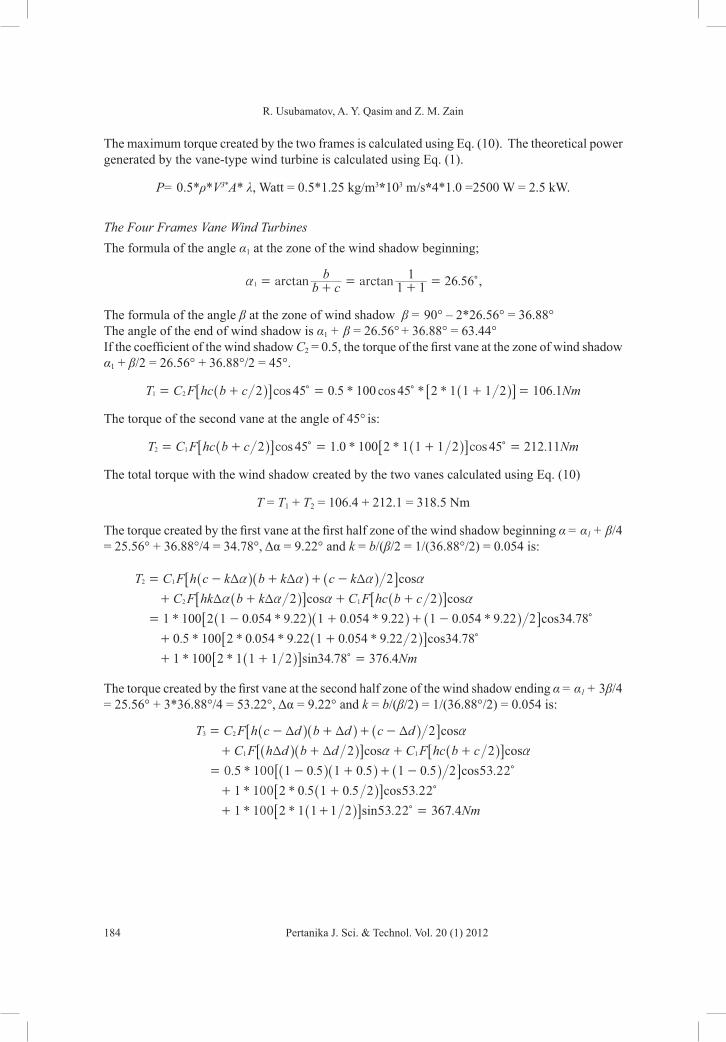
The maximum torque created by the two frames is calculated using Eq. (10). The theoretical power generated by the vane-type wind turbine is calculated using Eq. (1).
P= 0.5*ρ*V3*A* λ, Watt = 0.5*1.25 kg/m3*103 m/s*4*1.0 =2500 W = 2.5 kW.
The Four Frames Vane Wind TurbinesThe formula of the angle α1 at the zone of the wind shadow beginning;
.arctan arctanb cb
1 11
26 561a =+
=+
= c,
The formula of the angle β at the zone of wind shadow β = 90° – 2*26.56° = 36.88°The angle of the end of wind shadow is α1 + β = 26.56° + 36.88° = 63.44°If the coefficient of the wind shadow C2 = 0.5, the torque of the first vane at the zone of wind shadow α1 + β/2 = 26.56° + 36.88°/2 = 45°.
. * * * .cos cosT C F hc b c Nm2 45 0 5 100 45 2 1 1 1 2 106 11 2= + = + =c c^ ^h h6 6@ @
The torque of the second vane at the angle of 45° is:
. * * .cos cosT C F hc b c Nm2 45 1 0 100 2 1 1 1 2 45 212 112 1= + = + =c c^ ^h h6 6@ @
The total torque with the wind shadow created by the two vanes calculated using Eq. (10)
T = T1 + T2 = 106.4 + 212.1 = 318.5 Nm
The torque created by the first vane at the first half zone of the wind shadow beginning α = α1 + β/4 = 25.56° + 36.88°/4 = 34.78°, Δα = 9.22° and k = b/(β/2 = 1/(36.88°/2) = 0.054 is:
* . * . . * . . * . .
. * * . * . . * . .
* * . .
T C F h c k b k c kC F hk b k C F hc b c
Nm
2
2 2
1 100 2 1 0 054 9 22 1 0 054 9 22 1 0 054 9 22 2 34 78
0 5 100 2 0 054 9 22 1 0 054 9 22 2 34 78
1 100 2 1 1 1 2 34 78 376 4
cos
cos cos
cos
cos
sin
2 1
2 1
T T T
T T
a a a a
a a a a
= - + + -
+ + + +
= - + -
+ +
+ + =
+ c
c
c
^ ^ ^
^ ^
^ ^ ^
^
^
h h h
h h
h h h
h
h
66 66
66
@@ @
@@
@
The torque created by the first vane at the second half zone of the wind shadow ending α = α1 + 3β/4 = 25.56° + 3*36.88°/4 = 53.22°, Δα = 9.22° and k = b/(β/2) = 1/(36.88°/2) = 0.054 is:
0.5 * 100 . . . 53.22
1 * 100 * . . 53.22
1 * 100 * 53.22 367.4
T C F h c d b d c dC F h d b d C F hc b c
Nm
2
2 2
1 0 5 1 0 5 1 0 5 2
2 0 5 1 0 5 2
2 1 1 1 2
cos
cos cos
cos
cos
sin
3 2
1 1
T T T
T T
a
a a
= - + + -
+ + + +
= - + + -
+ +
+ + =
c
c
c
^ ^ ^
^ ^ ^
^ ^ ^
^
^
h h h
h h h
h h h
h
h
66 6
666
@@ @
@@
@

New Vane-Type Wind Turbine of High Efficiency
185Pertanika J. Sci. & Technol. Vol. 20 (1) 2012
The Three-framed Vane Wind TurbineThe formula of the angle α = 30° + α1 at the zone of the wind shadow beginning
c bb
30cos
sin
1
1
aa
+=
+c^ h
. ..
. .c b b0 866
1 1 1
0 86619 1
0 5 0 5arctan arctan1a =
+=
+=
+ +c
^ ^h h6 6@ @.30 49 11a a= + =c c
The formula of the angle β at the zone of wind shadow is:
β = 90° – 30° – 2α1 = 60° – 2*19.1° = 21.8°
The formula of the angle α at the zone of the ending wind shadow;
α = 30° + α1 + β = 30° +19.1° + 21.8° = 70.9°
a) If the coefficient of the wind shadow C2 = 0.5, the torque created by the first frame vane at zone of full wind shadow at the angle α = 30° + α1 + β/2 = 30° + 19.1° + 21.8°/2 = 60°
0.5 * 100 * * 75.0T C F hc b c Nm2 60 60 2 1 1 1 2cos cos1 2= + = + =c c^ ^h h6 6@ @
The torque of the second frame vane at the angle 600 of the first frame turns.
* 100 * 3 .03 1.0 sinT C F hc b c Nm2 0 2 1 1 1 2 0 150cos2 1= + = + =c c^ ^h h6 6@ @
The total torque created by the two vanes at the zone of the wind shadow is calculated using Eq. (10):
T= T1 + T2 = 75.0 + 150 = 225 Nm
b) The torque created by the first vane at the first half zone of the wind shadow beginning at the angle α = 30° + α1 + β/4 = 30° + 19.1° + 21.8°/4 = 54.55°, Δα = 5.45° and k = b/(β/2) = 1/(21.8°/2) = 0.092 is:
* . * 1 0.092 * 5.45 1 0.092 * 5.45
0.5 * 100 2 * 0.092 * 5.45 0.092 * 5.45 54.55
. .
T C F h c k b k c kC F hk b k C F hc b c
2
2 2
1 100 2 1 0 0 2
1 2
92 5 45 54 55
cos
cos cos
cos
cos
1 1
2 1
T T T
T T
a a a a
a a a a
= - + + -
+ + + +
= - + + -
+ +
c
c
^ ^ ^
^ ^
^ ^ ^
^
h h h
h h
h h h
h
66 66
6
@@ @
@@
The torque created by the second frame vane at the angle of 54.550 of the first frame turns
1 * 100 * 24.55T 2 1 1 1 2 sin2 = + c^ h6 @

R. Usubamatov, A. Y. Qasim and Z. M. Zain
186 Pertanika J. Sci. & Technol. Vol. 20 (1) 2012
c) The torque created by the first vane at the second half zone of the wind shadow ending at the angle α = 30° + α1 + 3β/4 = 30° + 19.1° + 3*21.8°/4 = 65.45°, Δα = 5.45° and k = b/(β/2) = 1/(21.8°/2) = 0.092 is:
. * .
* 100 * 65.45 * * 65.45
. . .
1 . . sin
T C F h c d b c dC F h d b d C F hc b c
d 2
2 2
0 5 100 2 1 0 1 1 2
2 1 2 1 100 2 1 1 1 2
5 0 5 0 5 65 45
0 5 0 5
cos
cos cos
cos
cos
1 2
1 1
T T T
T T
a
a a
= - + + -
+ + + +
= - + + -
+ + + +
c
c c
^ ^ ^
^ ^
^ ^ ^
^ ^
h h h
h h
h h h
h h
66 6
66 6
@@ @
@@ @
The torque created by the second frame vane at the angle 65.45° of first frame turns:
* * .sinT 1 100 2 1 1 1 2 35 452 = + c^ h6 @
d) If coefficient of wind shadow C = 0.5, the maximum torque created by the first vane at the zone of wind shadow at the angle is α + β/2 = 30.96° + 14.04° = 45
T1 = 0.5* 141.4 Nm = 70.07 Nm
The total torque is created by the vanes at the zone of the wind shadow.
T= T1 + T2 = 141.4 + 70.07 = 211.47 Nm
The power generated by the four- and three-framed vane-type wind turbine is expressed by the following formula:• Four frame, P = TV/R = 360*10/1.5 = 2400 W = 2.4 kW
where the torque T = 360 Nm is average from the diagram (Fig. 4)• Three frame, P = TV/R = 260*10/1.5 = 1733.3 W = 1.7 kW
where the torque T = 260 Nm is average from the diagram (Fig. 4)
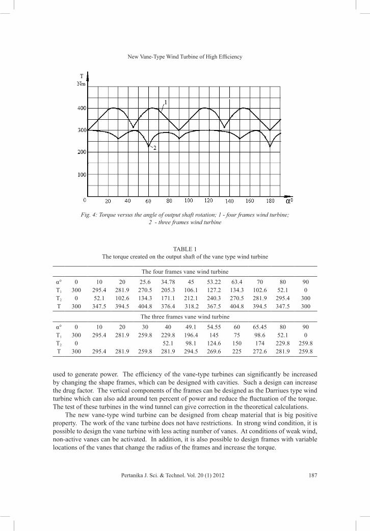
The diagram (Fig. 4) and Table 1 show that the torque and power respectively for the vane-type wind turbine have fluctuation that is numerically expressed by the following data:
%TT T
100max
max mind =-
The four frames turbine 100%.
.% %T
T T404 8
404 8 300100 26
max
max mind =-
=-
=
The three frames turbine 100% %300
300 22525d =
-=
The torque fluctuation of both type turbines has a small difference and is dependent on the torque loss due to the wind shadow of the vanes.
RESULTS AND DISCUSSIONThe theoretical calculations of the torque created by the vane-type turbines conducted by Equations (1) and (2) show almost the same result. The difference can be explained by the accepted efficiency factor λ, which can vary. Nevertheless, the results also show that this type wind turbines can be
New Vane-Type Wind Turbine of High Efficiency
187Pertanika J. Sci. & Technol. Vol. 20 (1) 2012
used to generate power. The efficiency of the vane-type turbines can significantly be increased by changing the shape frames, which can be designed with cavities. Such a design can increase the drug factor. The vertical components of the frames can be designed as the Darriues type wind turbine which can also add around ten percent of power and reduce the fluctuation of the torque. The test of these turbines in the wind tunnel can give correction in the theoretical calculations.
The new vane-type wind turbine can be designed from cheap material that is big positive property. The work of the vane turbine does not have restrictions. In strong wind condition, it is possible to design the vane turbine with less acting number of vanes. At conditions of weak wind, non-active vanes can be activated. In addition, it is also possible to design frames with variable locations of the vanes that change the radius of the frames and increase the torque.
Fig. 4: Torque versus the angle of output shaft rotation; 1 - four frames wind turbine; 2 - three frames wind turbine
TABLE 1 The torque created on the output shaft of the vane type wind turbine
The four frames vane wind turbine
α° 0 10 20 25.6 34.78 45 53.22 63.4 70 80 90T1 300 295.4 281.9 270.5 205.3 106.1 127.2 134.3 102.6 52.1 0T2 0 52.1 102.6 134.3 171.1 212.1 240.3 270.5 281.9 295.4 300T 300 347.5 394.5 404.8 376.4 318.2 367.5 404.8 394.5 347.5 300
The three frames vane wind turbine
α° 0 10 20 30 40 49.1 54.55 60 65.45 80 90T1 300 295.4 281.9 259.8 229.8 196.4 145 75 98.6 52.1 0T2 0 52.1 98.1 124.6 150 174 229.8 259.8T 300 295.4 281.9 259.8 281.9 294.5 269.6 225 272.6 281.9 259.8

R. Usubamatov, A. Y. Qasim and Z. M. Zain
188 Pertanika J. Sci. & Technol. Vol. 20 (1) 2012
CONCLUSIONSThe new vane type wind turbine possesses many positives properties of the horizontal and vertical designs of the wind turbines and can be concurrent for the known wind turbine designs, especially for the low speed of the wind. The new turbine presents simple construction, uses a simple technology for manufacturing and be produced from cheap material. Thus, it is possible to design new turbines that can operate in any conditions of the wind force change. For future research, a mathematical modelling of the wind turbine work should be conducted on a theoretical basis of computational fluid dynamics and proved through practical investigations in the wind tunnel. In addition, it is necessary to conduct investigations on the optimal design of the new turbines (power as function of the vanes geometry, weight of turbine, aerodynamic shape, wind speed, etc.). Tests of the vane-type wind turbine in the wind tunnel and correction of the mathematical model can give reliable data to design an effective vane-type wind turbine.
REFERENCESBetz, A. (1996). Introduction to the Theory of Flow Machines. (D. G. Randall, Trans.) Oxford: Pergamon Press.
Cermak, J. E. (1975). Applications of Fluid Mechanics to Wind Engineering, A Freeman Scholar Lecture. ASME Journal of Fluids Engineering, 97(1), 9-38.
Heier, S. (1988). Grid Integration of Wind Energy Conversion Systems. New York: John Wilеу & Sons, Inc.
Iwashita, H, Y. D. et al. (2004). Development of an Elastic Rotor-Blade for the Horizontal Axis Wind Turbine. Proceedings of Wind energy symposium, pp. 187-190.
Manwell, J. F., McGowan, J. G., & Rogers, A. L. (2002). Wind Energy Explained. England: John Wiley & Son Ltd.
Mathew, S. (2006). Wind Energy Fundaments, Resource Analysis and Economics (1st ed.) Vol. 1. Springer.
Munson, B. R., Donald, F. Y., & Theodore Н. O. (2002). Fundamentals of Fluids Mechanics (4th ed). John Wilеу & Sons, Inc.
Spera, D. А. (1994). Wind Turbine Technology. New York: ASME Press.
Usubamatov, R., & Usdubamatov, D. (2007). Vane type wind turbine. Patent # 901, Kyrgyz Republic.
Usubamatov, R. et al. (2009). Wind power station, Malaysian patent, MY-138117, A. 30.04.2009.