new technology of the global twin breaker “g-twin series”leakage circuit breakers (elcb)...
TRANSCRIPT
1. Introduction
Molded case circuit breakers (MCCB) and earth leakage circuit breakers (ELCB) function to protect wiring, equipment and human body from electrical accidents, such as the application of an overcurrent to distribution lines and loads, or the occurrence of a short circuit, ground fault or earth leakage in a distri-bution circuit. These circuit breakers are installed in all types of devices, machinery and buildings that use electricity.
In 1990, Fuji Electric released its “Twin Breaker Series” that featured MCCBs and ELCBs with common external dimensions for the first time in the world, and as a result of the improved convenience due to installa-tion interchangeability and the ability to share acces-sories, as well as contributions to the standardization and miniaturization of switch board equipment and systems, this series has received the support of many customers. Meanwhile, in response to recent requests from customers who are expanding their global busi-nesses, rather than the previous implementation in which successive variations of products were certified to meet individual standards, a single series of global MCCBs/ELCBs capable of satisfying all standards is believed to be necessary, and for this purpose Fuji Electric has developed and released the “G-TWIN” breaker series that combines the concepts of “global” products with that of “twin” breakers. In January 2009, the entire series, ranging from 32 to 800 AF, was completed (see Tables 1, 2 and 3) and a full-scale mar-keting campaign was conducted.
The basic development concept of combining com-patibility with the new JIS/IEC standard and the UL489 standard, and the development of the elemental
technology have already been described in other pa-pers(1),(2).
Using the example of the 125 AF, this paper describes high performance current-limiting breaker technology for low-rated-current products, as innova-tive technology for enhancing the current-limiting performance of branch circuit breakers in order to coordinate tripping with devices connected in lower level. Also introduced are products that support plug-in circuit breakers and their expanded application to DC circuits, for which demand is expected to grow in the near future from the perspective of power supply stability and reliability.
2. High Performance Current Limiting Breaker Technology for Low-Rated 125 AF Products
The breaking capacity of low voltage circuit break-ers that use a molded case is primarily determined according to the tolerable limit of stress that is created by arc energy generated during a breaking operation. If the stress cannot be controlled, the sudden increase in internal pressure will damage the molded case, the dielectric strength will deteriorate due to the melting and scattering of conductive materials and insulation materials at high temperature, the operation of the switching mechanism will malfunction, and so on.
The prior series of UL-standard products were intended for the North American market, and as such, were separate from the Twin Breaker Series. Compared to the Twin Breaker Series, this prior series featured larger external dimensions and also a larger-sized breaking mechanism and main contact separat-ing distance, and had ample tolerance against stress.
In the course of developing the G-TWIN breaker which, within the same external dimensions, satisfies both the new JIS/IEC standard and the UL standard,
97
† Fuji Electric FA Components & Systems Co., Ltd.
Yasumichi Okamoto † Akifumi Sato † Yoshinobu Hamada †
New Technology of the Global Twin Breaker “G-TWIN Series”
A B S T R A C T
Against the backdrop of market globalization, Fuji Electric has developed and commercialized the “G-TWIN” global breaker, and upon completing the 32 to 800 AF series in January 2009, launched a full-scale effort to expand the market. Because of the relationship of protective coordination with lower devices, a fork-type dual-contact breaking method was adopted as new technology for compact high performance current-limiting breaking. Moreover, to ensure the stability and reliability of the supply of electric power, Fuji Electric has expanded its lineup of plug-in circuit breaker models, and demand for these models is expected to increase in recent years. Fuji Electric has also developed a proprietary arc extinguishing function and expanded its lineup of breaker models for use in photovoltaic cells and the DC circuits in data centers.

Issu
e:S
witc
hing
, Ope
ratio
n/D
ispl
ay a
nd C
ontro
l Dev
ices
the development of a new breaking mechanism with increased current-limiting effect was needed.
To increase the breaking capacity, the most effec-tive method is to increase the arc voltage by separating the contacts at high-speed beginning at the time when a short circuit occurs, and to limit the current to a coolable current value. With the G-TWIN Breaker, to improve the current-limiting performance of the low-rated-current region, in addition to techniques used with high-rated-current products, a forked dual-con-tact breaking method was newly developed to realize technology for further improving the current-limiting effect. Such techniques were utilized from high-rated-current products as enhancing the ablation effect with the narrow slit resin, optimally arranging the mag-netic yoke for promoting arc driving, and reducing the emission of ionized gas on the load side by adopting an isolated construction of the molded casing.
Characteristics of the breaking mechanisms of high-rated-current products and low-rated-current products are shown in Figs. 1 and 2, and a sketch of
the breaking mechanism for low-rated-current prod-ucts is shown in Fig. 3.
The principles of electromotive force generation with the forked dual-contact breaking method are shown in Fig. 4. The primary-side fixed contact connected to the line-side terminal is folded into a U-shape, and joined to a contact tip. The opposed mov-able contact is folded into a C-shape in the width direc-tion of the breaker, and via a secondary-side contact,
98New Technology of the Global Twin Breaker “G-TWIN Series”
Table 1 “G-TWIN Standard Series” (wiring-use)
Frame(A)
Rated breaking capacity Icu (kA) MCCB ELCB
230 Vac 440 Vac
32
2.5 – EW32AAG
2.5 1.5 BW32AAG EW32EAG
5 2.5 BW32SAG EW32SAG
50
2.5 1.5 BW50AAG EW50AAG
5 2.5 BW50EAG EW50EAG
10 7.5 BW50SAG EW50SAG
25 10 BW50RAG EW50RAG
125 65 BW50HAG EW50HAG
63
5 2.5 BW63EAG EW63EAG
10 7.5 BW63SAG EW63SAG
25 10 BW63RAG EW63RAG
1005 1.5 BW100AAG EW100AAG
25 10 BW100EAG EW100EAG
125
50 30 BW125JAG EW125JAG
100 50 BW125RAG EW125RAG
125 65 BW125HAG EW125HAG
250
36 18 BW250EAG EW250EAG
50 30 BW250JAG EW250JAG
100 50 BW250RAG EW250RAG
125 65 BW250HAG EW250HAG
400
50 30 BW400EAG EW400EAG
85 36 BW400SAG EW400SAG
100 50 BW400RAG EW400RAG
125 70 BW400HAG EW400HAG
630
50 36 BW630EAG EW630EAG
100 50 BW630RAG EW630RAG
125 70 BW630HAG EW630HAG
800
50 36 BW800EAG EW800EAG
100 50 BW800RAG EW800RAG
125 70 BW800HAG EW800HAG
Table 2 “G-TWIN Global Series” (wiring-use)
Frame(A)
Rated breaking capacity Icu (kA) MCCB ELCB
230 Vac 440 Vac
50 25 10 BW50RAGU EW50RAGU
100 25 10 BW100EAGU EW100EAGU
12550 30 BW125JAGU EW125JAGU
100 50 BW125RAGU EW125RAGU
250
36 18 BW250EAGU
50 30 BW250JAGU EW250JAGU
100 50 BW250RAGU EW250RAGU
400
50 30 BW400EAGU
85 36 BW400SAGU EW400SAGU
100 50 BW400RAGU EW400RAGU
125 70 BW400HAGU EW400HAGU
630
50 36 BW630EAGU
100 50 BW630RAGU EW630RAGU
125 70 BW630HAGU
800
50 36 BW800EAGU
100 50 BW800RAGU
125 70 BW800HAGU
Table 3 Variant usage of the “G-TWIN Standard Series”
Frame(A)
For electric m
otor protection
For u
se with
primary-side of tran
sformer
Instan
taneou
s tripping
Non
-auto sw
itch
With
leakage alarm
For u
se with
resistance w
elder
4-pole product
DC
-only produ
ct
32 ○ ○ ○ ○ ○50 ○ ○ ○ ○ ○ ○63 ○ ○ ○ ○100 ○ ○ ○ ○ ○125 ○ ○ ○ ○ ○ ○ ○250 ○ ○ ○ ○ ○ ○ ○ ○400 ○ ○ ○ ○ ○ ○ ○630 ○ ○ ○ ○ ○ ○800 ○ ○ ○ ○ ○

opposes the fixed contact. The secondary-side fixed contact extends outward in a straight line and is con-nected to an overcurrent release. When a short-circuit current occurs, an electromotive force is generated between each of the respective primary-side and sec-ondary-side fixed and movable contacts, and with the added effect of a magnetic yoke, the two contacts sepa-rate simultaneously at high-speed. The arc generated between the contacts is generated in series at the pri-mary and secondary sides. Therefore, the rate of rise
of the arc voltage (dV /dt) is approximately twice that of a single contact. Moreover, by ensuring twice the contact separation distance with the same arc-quench-ing chamber space as for a single contact, a peak value of arc voltage that is approximately twice as large can be realized, and the current-limiting effect is enhanced significantly. The arc voltages for the forked structure and prior structure are compared in Fig. 5.
By applying these techniques, an approximate 15 % reduction in I2t was realized in comparison to the prior series of breakers, and at the same time, perfor-mance that satisfies the UL489 standard was realized in a Japanese standard-size breaker shape. Moreover, the Twin Breaker concept of uniform dimensions for the MCCB and ELCB is maintained and parts for the make-and-break mechanisms in 40 A and higher rated products can also be shared.
3. High Reliability and High Efficiency Power Supply system technology
3.1 Plug-in type circuit breakersIn recent years, from the perspective of simplify-
ing and reducing the amount of labor involved in the installation of equipment, improving the stability and maintainability of the electric power supply, and reducing the environmental load, plug-in type circuit breakers have attracted attention and have begun to
Fig.1 Features of large current rated (40 to 125 A) breaker structures
Arc-quenching chamber
Movable contact
Fixed contactNarrow slit resin + magnetic yoke
Molded case
Fig.4 Principle of electromotive force generation according to contact shape
Line-side terminal
Current path
Arc between contacts
Electromotive force
Second contact tip
Second fixed contactFirst contact tipFirst fixed contact
Movable contact
Fig.3 Breaker structure of small current rated device
Grid Arc driving force
Narrow slit resinMagnetic yoke
Arc
Fig.5 Comparison of arc voltages
Arc
vol
tage
(V
)
Forked structure
Prior model
Time (ms)
Fig.2 Features of small current rated (15 to 30 A) breaker structures
Arc-quenchingchamber
Movable contact
Fixed contact
Narrow slit resin + magnetic yoke
Molded case
99 Vol. 56 No. 3 FUJI ELECTRIC REVIEW
Issu
e:S
witc
hing
, Ope
ratio
n/D
ispl
ay a
nd C
ontro
l Dev
ices
be used widely in facilities such as data centers and public utilities where a highly reliable supply of elec-tric power is required.
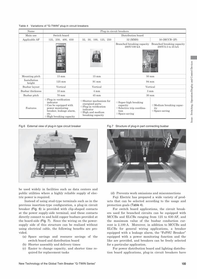
Instead of using stud-type terminals such as in the previous insertion-type configuration, a plug-in circuit breaker (Fig. 6) is provided with clip-shaped contacts at the power supply-side terminal, and these contacts directly connect to and hold copper busbars provided at the board-side (Fig. 7). Since the wiring on the power-supply side of this structure can be realized without using electrical cable, the following benefits are pro-vided.
(a) Space savings and resource savings of the switch board and distribution board
(b) Shorter assembly and delivery times(c) Easier to change capacity, and shorter time re-
quired for replacement tasks
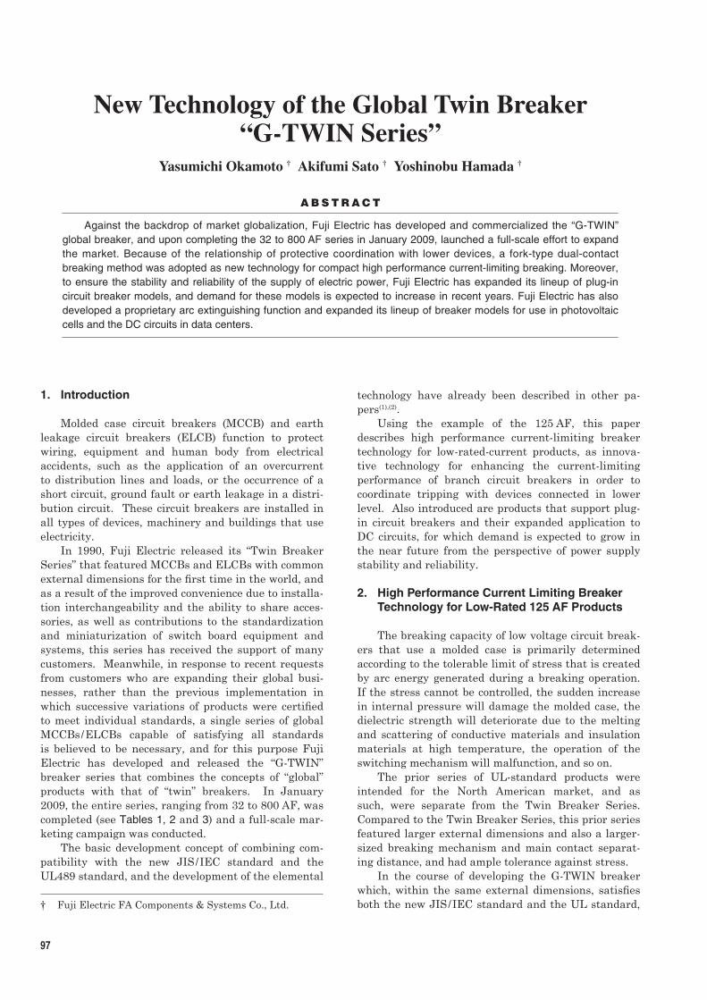
(d) Prevents work omissions and misconnectionsFuji Electric has prepared a wide variety of prod-
ucts that can be selected according to the usage and protection goals (Table 4).
For switch board applications, the circuit break-ers used for branched circuits can be equipped with MCCBs and ELCBs ranging from 125 to 630 AF, and the maximum value of the busbar conduction cur-rent is 2,100 A. Moreover, in addition to MCCBs and ELCBs for general wiring applications, a breaker equipped with a leakage alarm, the “FePSU Breaker” equipped with a power monitoring function and the like are provided, and breakers can be freely selected for a particular application.
For power distribution board and lighting distribu-tion board applications, plug-in circuit breakers have
Fig.6 External view of plug-in type circuit breaker Fig.7 Structure of plug-in part connecting busbar
Table 4 Variations of “G-TWIN” plug-in circuit breakers
Name Plug-in circuit breakers
Main use Switch board Distribution board
Applicable AF 125,250,400,630 32,50,100,125,250 32 (MMS) 50 (MCCB-2P)
Branched breaking capacity200V/100 kA
Branched breaking capacity200V/2.5 to 25 kA
Mounting pitch 15 mm 15 mm 50 mmInstallation
height 125 mm 91 mm 94 mm
Busbar layout Vertical Vertical Vertical
Busbar thickness 10 mm 4 mm 3 mm
Busbar pitch 70 mm 45 mm 30 mm
Features
™ Plug-in verification indicator
™ Can be equipped with power monitoring breaker, leakage alarm, etc.
™ High breaking capacity
™ Shutter mechanism for energized parts
™ Plug-in verification indicator
™ High and medium breaking capacity
™ Super-high breaking capacity
™ Selective trip coordina-tion
™ Space-saving
™ Medium breaking capac-ity
™ Space-saving
100New Technology of the Global Twin Breaker “G-TWIN Series”

been prepared in two varieties, with 32 to 250 AF or 32 to 50 AF, which enable further reductions in the size of switch boards. Also, “manual motor starter (MMS)” installation is also possible, and as a result of the su-per-high current-limiting breaking performance of an MMS, selective trip coordination with an upper-level circuit breaker can be implemented, thereby contrib-uting to the realization of a reliable supply of electric power. Moreover, except for a few models, safety-relat-ed options, such as a safety shutter function that closes off the busbar when the breaker has been removed or a gauge function that verifies the plug-in status are also available.
3.2 “G-TWIN” DC breaker seriesIn recent years, with the increased popularity of
green energy such as solar power and also with the widespread prevalence of data centers, requests for a more highly reliable and efficient supply of power have intensified, and there is growing demand to changeover from conventional AC power transmission and distribution to DC power transmission and dis-tribution. Especially for data centers, decreasing the amount of AC-DC conversion is said to enable a reduc-tion in power transmission loss of up to 10 or 20%, and the energy saving effect would be large. Additionally, higher voltage transmission and distribution technol-ogy has also been requested in recent years in order to reduce transmission loss.
In an AC circuit, a current zero-point generally oc-curs periodically, and at a zero-point, if the insulation can be maintained, the current can easily be interrupt-ed (see Fig. 8). But in a DC circuit, because there is
no zero point, a technique for boosting the arc voltage generated between contacts to a level greater than the power supply voltage is needed in the breaker to inter-rupted the current (create a zero point) (see Fig. 9). Additionally, as the power supply voltage increases,
Fig.8 Current waveforms of AC and DC circuits
I
t
I
t
No current zero-pointCurrent zero-points exist
(a) AC circuit (b) DC circuit
Fig.9 DC circuit current breaking waveform
Arc voltage
Power supplyvoltage
t
Arc
Current
Start of contactsseparation
Table 5 “G-TWIN DC Series” lineup
Rated DC
voltage(V)
Basic model
No. of
poles
Rated cur-rent (A)
Breaking capacity Icu (kA)
EAG JAG SAG RAG HAG
250
BW32□*
2-pole
3to32
– – 2.5 – –
BW50BW63
5to63
2.5 – 5 5 –
BW10050to
1005 – – – –
BW12515to
125– 15 – 40 –
BW250125to
25010 20 – 30 –
BW400250to
40020 – 20 40 40
BW630BW800
500to
80020 – – 40 40
400
BW32
3-pole
3to32
– – 2.5 – –
BW50BW63
5to63
– – 5 – –
BW10050to
1005 – – – –
500
BW50
3-pole
5to50
– – 2.5 – –
BW10050to
1002.5 – – – –
BW12515to
125– 10 – 20 –
BW250125to
250– 10 – 20 –
BW400250to
400 20 – 20 40 40
BW630BW800
500to
80020 – – 40 40
600
BW125
4-pole
15to
125– – – 25 –
BW250125to
250– 25 – 40 –
BW400250to
400– – – 40 40
BW630BW800
500to
800– – – 40 40
* : indicates the breaker capacity type
101 Vol. 56 No. 3 FUJI ELECTRIC REVIEW

Issu
e:S
witc
hing
, Ope
ratio
n/D
ispl
ay a
nd C
ontro
l Dev
ices
device miniaturization becomes more difficult as the arc-quenching mechanism must be made larger in size and the distance between contacts increased.
By developing a proprietary arc-quenching mecha-nism for DC applications, Fuji Electric has established efficient breaking technology. Further, by wiring 3-pole or 4-pole circuit breakers in series and main-taining the contact separation distance, these circuit breakers can be applied to block even higher voltages. As a result, compared to the applicable range of up to DC250 V with a standard breaker, the “G-TWIN DC Series” can be applied to voltage circuits of 400 to 500 V for 3-pole circuit breaker or up to 600 V for 4-pole breakers (125 to 800 AF), and with its wide range of AF specifications, the G-TWIN Series offers a product lineup suitable for a wide range of needs (see Table 5). Additionally, switches (non-auto SW) that do not contain overcurrent protection elements have also been developed into a product series, and the select-able range of models is expanding.
3.3 DC breakers variations(1) 2 or 3 parallel phase energizing breakers
Specifications for parallel phase energizing break-ers for low-voltage DC circuit applications have recent-ly been added to the lineup of the G-TWIN DC Series (see Table 6).
These breakers are mainly used in applications involving DC power supply equipment for mobile base stations and the like (see Fig. 10), and since the cur-rent flow is divided into 2 or 3 phases, the current flow per phase is small, and the ability to realize conduc-tion in excess of the previous maximum rating for each AF contributes to the miniaturization of devices and switch boards. (2) Compact disconnecting switch for solar power ap-
plicationsIn the field of solar power, which has become
widely popular, the installation of a disconnecting switch is required by the JIS C60364-5-55 standard in order to permit the maintenance and inspection of solar inverters. Also, aiming to raise the power gener-ating efficiency of solar cells, the trend towards higher voltages is being advanced. In response, Fuji Electric has developed a compact arc-quenching mechanism that adds a permanent magnet to the conventional arc-quenching mechanism, and has also developed a compact disconnecting switch that is optimally suited for solar power generation. Designed to have the same size as an AC output-side ELCB, this breaker model contributes to the standardization of switch board de-sign and the miniaturization of solar cell equipment.
4. Postscript
The elemental technologies of the G-TWIN Breaker Series and the various models introduced to the market have been described above. In the future, with advances in the reliability, safety and efficiency of electrical equipment both in Japan and overseas, a product lineup suited to the market needs, such as for selective trip coordination and DC distribution, and the improvement of product quality are expected to be-come increasingly important. By accurately assessing the requirements of its customers, Fuji Electric intends to continue to expand its offering of products, such as the G-TWIN Breakers, that are responsive to the needs of the market, and to broaden the lineup of its product series.
References(1) Kuboyama, K. et al., New Global MCCB/ELCB G-Twin
Series. Fuji Electric Journal. 2006, vol.79, no.2, p.160-166.
(2) Takahashi, Y. et al, Expanded Product Lineup of the G-Twin Series and Accessories to Enhance Functional-ity. Fuji Electric Journal. 2008, vol.81, no.3, p.237-241.
Table 6 “G-TWIN” specifications of 2 or 3 parallel phases energizing breakers
Model AF No. of poles
Rated current (max.)
Rated breaking capacity (Icu)
60 Vdc 125 Vdc
BW32 322P 40 A
7.5 kA 5 kA3P 60 A
BW50 502P 75 A
20 kA 10 kA3P 100 A
BW63 632P 90 A
20 kA 10 kA3P 125 A
BW100 1002P 150 A
15 kA 10 kA3P 225 A
BW125 1252P 175 A 30 kA 20 kA
3P 250 A 60 kA 40 kA
BW250 250 3P 550 A 60 kA 40 kA
BW400 400 3P 950 A 80 kA 60 kA
BW630 630 3P 1,400 A 80 kA 60 kA
BW800 800 3P 1,900 A 80 kA 60 kA
Fig.10 2 or 3 parallel phases energizing breaker
102New Technology of the Global Twin Breaker “G-TWIN Series”

* All brand names and product names in this journal might be trademarks or registered trademarks of their respective companies.