new stainless twip steel fe-17cr-mnnicu: mechanical ... · then hot rolled (final thickness 3mm)...
TRANSCRIPT

La Metallurgia Italiana - n. 3 2017 37
Processo termomeccanico
INTRODUCTIONThe fundamental mechanisms of plastic deformation in steel are the dislocation glide and mechanical twins. These mechanisms are competitive and, in any situation, the one requiring the lower stress is prevalent. The stacking fault energy (SFE) is the metallur-gical parameter controlling which mechanism is prevalent. In the face-centered cubic (FCC) lattice the ordinary dislocations under low SFE conditions become unstable and tend to separate into two partials (Shockley dislocations). The region between the two partials is characterized by a stacking fault in which the normal sequence of the lattice close-packed planes changes from the face-centered cubic lattice (FCC) to a compact hexagonal lattice (HCP). The mobility of the dislocations is significantly affected as well as the process of cross slip.Steels exhibiting twinning induced plasticity (TWIP steels) are characterized by a high work hardening because the twins which develop during deformation represent an obstacle to the dislocation motion (dynamic Hall-Petch effect) [1,2]. Austenitic stainless steels are characterized by a relatively wide range of stacking fault energy value. Nevertheless works reporting the oc-currence of TWIP effect and the role played by mechanical twins in stainless steels are lacking. The present work is focused on the characterization of the TWIP effect in the steel Fe-17Cr-Mn-Ni-Cu in which the stabilization of the austenitic phase is obtained using manganese, copper, carbon and nitrogen [3].
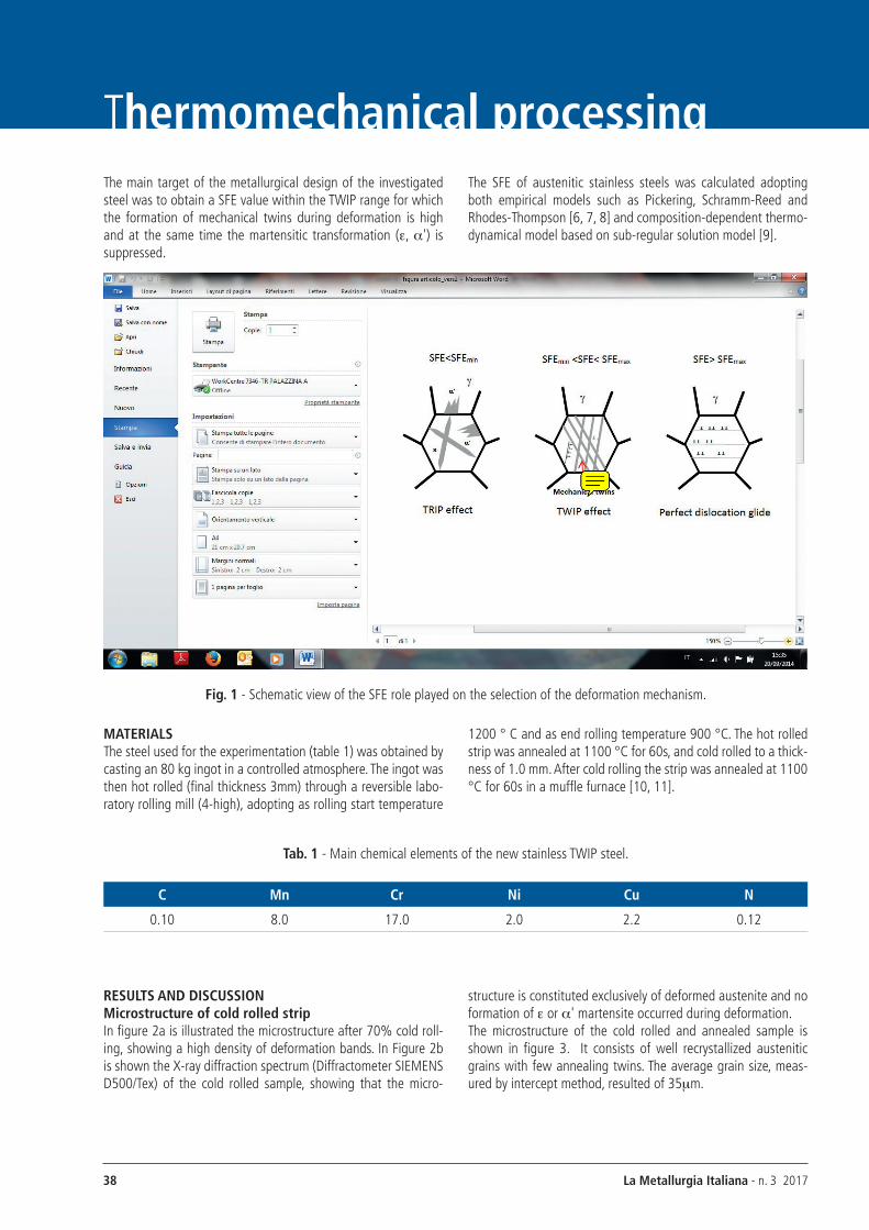
As illustrated schematically in figure 1 the TWIP effect is devel-oped in a given range of SFE values [3, 4, 5]. It is recognized now that for values of the SFE lower than 20mJ/m2 (SFEmin), a TRIP behavior (Transformation Induced Plasticity) appears during de-formation with the formation of e-martensite (HCP lattice) and a'-martensite (BCC lattice). On the other side, there is a maxi-mum value, SFEmax (about 45mJ/m2) such that for SFE>SFEmax, the dominant deformation mechanism is dislocation glide.The TWIP effect, that is the simultaneous presence of both dis-locations slip and mechanical twins during deformation, can only occur for SFE values ranging within the two critical values (SFEmin÷SFEmax).
New stainless TWIP steel Fe-17Cr-MnNiCu: mechanical properties
characterization and microstructure evolution during deformation
A. Ferraiuolo, S. Cicalè, A. Costa
A new austenitic stainless steel grade with low Ni and 8%wt Mn, revealing a pure TWIP behavior, was obtained through a proper design of the steel chemical composition and processing conditions. Room temperature tensile tests revealed a high strength and excellent elongation to rupture both at the same level of conventional high Mn TWIP steels. A modified Kocks-Mecking-Bouaziz work hardening model was used to characterize the nucleation rate of mechanical twins during straining in the temperature range -50°C ÷ 100°C. The microstructure evolution during deformation at room temperature was investigated on interrupted tensile tests by means of optical microscopy and EBSD image analysis. During tensile deformation, after a critical stress, shear bands and mechanical twins appear in the microstructure. The rapid increase in volume fraction of mechanical twins with the progress of de-formation creates additional obstacles for the dislocations gliding (dynamic Hall-Petch effect) promoting the rapid work hardening characteristic of the TWIP steels.
KEYWORDS: TWIP EFFECT - STAINlESS STEElS - lOW NICKEl - WORK HARDENINg ANAlySIS - SFE MEASuREMENT - TAylOR FACTOR
A. Ferraiuolo, S. CicalèCentro Sviluppo Materiali S.p.A., Roma, Italy
A. CostaAnsaldo Energia S.p.A., genova, Italy
La Metallurgia Italiana - n. 3 201738
Thermomechanical processingThe main target of the metallurgical design of the investigated steel was to obtain a SFE value within the TWIP range for which the formation of mechanical twins during deformation is high and at the same time the martensitic transformation (e, a') is suppressed.
The SFE of austenitic stainless steels was calculated adopting both empirical models such as Pickering, Schramm-Reed and Rhodes-Thompson [6, 7, 8] and composition-dependent thermo-dynamical model based on sub-regular solution model [9].
Fig. 1 - Schematic view of the SFE role played on the selection of the deformation mechanism.
MATERIALSThe steel used for the experimentation (table 1) was obtained by casting an 80 kg ingot in a controlled atmosphere. The ingot was then hot rolled (final thickness 3mm) through a reversible labo-ratory rolling mill (4-high), adopting as rolling start temperature
1200 ° C and as end rolling temperature 900 °C. The hot rolled strip was annealed at 1100 °C for 60s, and cold rolled to a thick-ness of 1.0 mm. After cold rolling the strip was annealed at 1100 °C for 60s in a muffle furnace [10, 11].
Tab. 1 - Main chemical elements of the new stainless TWIP steel.
C Mn Cr Ni Cu N
0.10 8.0 17.0 2.0 2.2 0.12
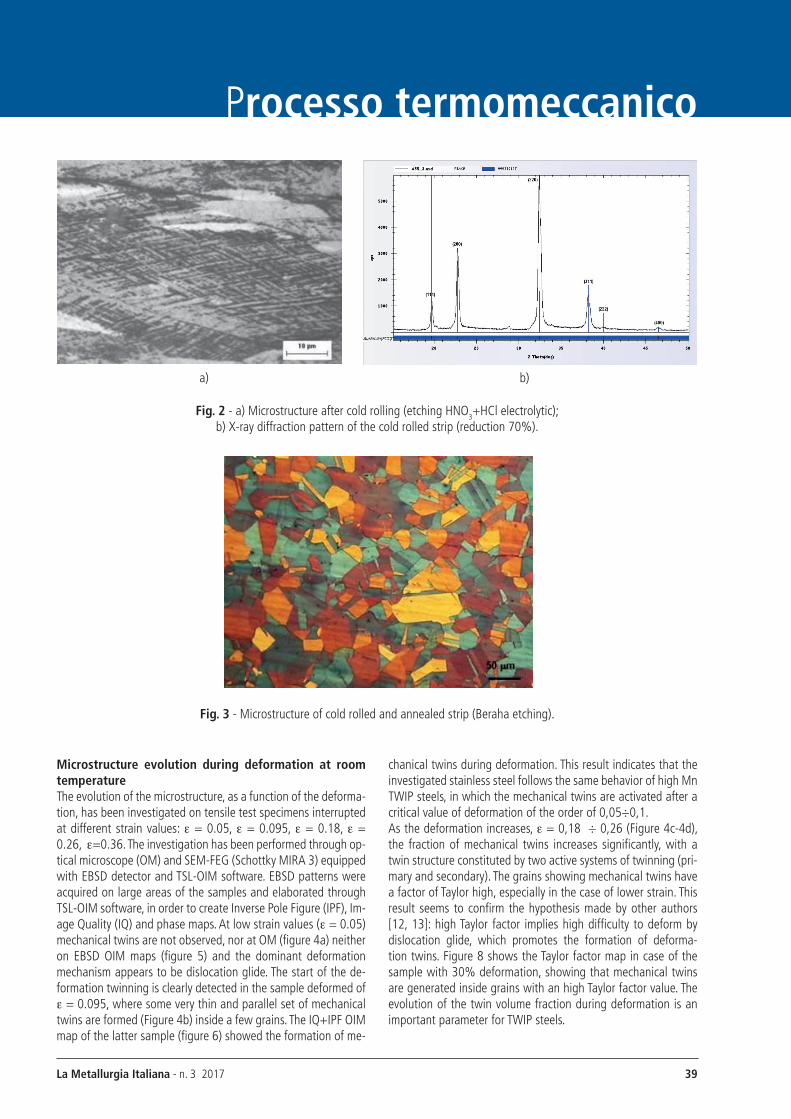
RESULTS AND DISCUSSION Microstructure of cold rolled strip In figure 2a is illustrated the microstructure after 70% cold roll-ing, showing a high density of deformation bands. In Figure 2b is shown the X-ray diffraction spectrum (Diffractometer SIEMENS D500/Tex) of the cold rolled sample, showing that the micro-
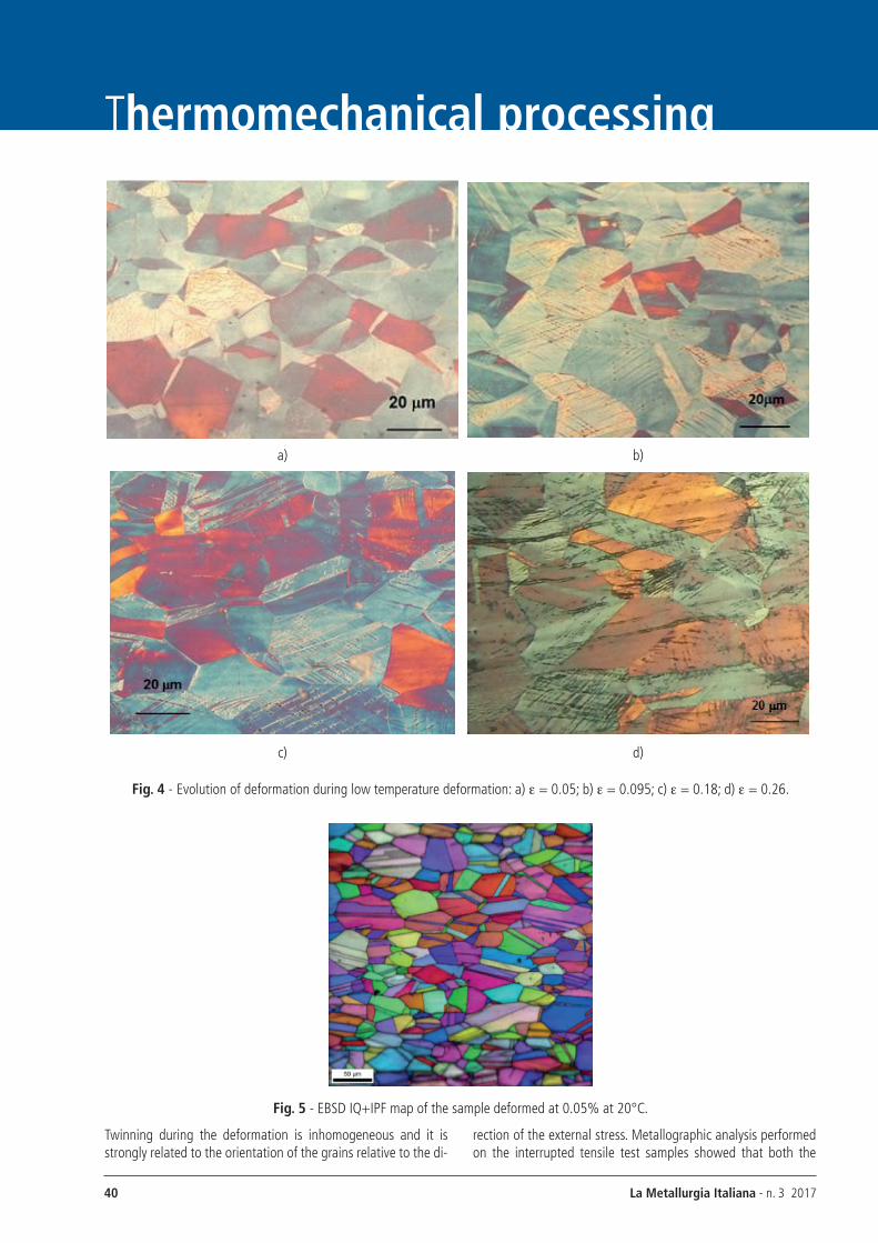
structure is constituted exclusively of deformed austenite and no formation of e or a' martensite occurred during deformation.The microstructure of the cold rolled and annealed sample is shown in figure 3. It consists of well recrystallized austenitic grains with few annealing twins. The average grain size, meas-ured by intercept method, resulted of 35mm.
La Metallurgia Italiana - n. 3 2017 39
Processo termomeccanico
a) b)
Fig. 2 - a) Microstructure after cold rolling (etching HNO3+HCl electrolytic); b) X-ray diffraction pattern of the cold rolled strip (reduction 70%).
Fig. 3 - Microstructure of cold rolled and annealed strip (Beraha etching).
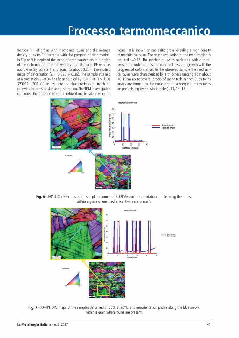
Microstructure evolution during deformation at room temperature The evolution of the microstructure, as a function of the deforma-tion, has been investigated on tensile test specimens interrupted at different strain values: e = 0.05, e = 0.095, e = 0.18, e = 0.26, e=0.36. The investigation has been performed through op-tical microscope (OM) and SEM-FEg (Schottky MIRA 3) equipped with EBSD detector and TSl-OIM software. EBSD patterns were acquired on large areas of the samples and elaborated through TSl-OIM software, in order to create Inverse Pole Figure (IPF), Im-age Quality (IQ) and phase maps. At low strain values (e = 0.05) mechanical twins are not observed, nor at OM (figure 4a) neither on EBSD OIM maps (figure 5) and the dominant deformation mechanism appears to be dislocation glide. The start of the de-formation twinning is clearly detected in the sample deformed of e = 0.095, where some very thin and parallel set of mechanical twins are formed (Figure 4b) inside a few grains. The IQ+IPF OIM map of the latter sample (figure 6) showed the formation of me-
chanical twins during deformation. This result indicates that the investigated stainless steel follows the same behavior of high Mn TWIP steels, in which the mechanical twins are activated after a critical value of deformation of the order of 0,05÷0,1. As the deformation increases, e = 0,18 ÷ 0,26 (Figure 4c-4d), the fraction of mechanical twins increases significantly, with a twin structure constituted by two active systems of twinning (pri-mary and secondary). The grains showing mechanical twins have a factor of Taylor high, especially in the case of lower strain. This result seems to confirm the hypothesis made by other authors [12, 13]: high Taylor factor implies high difficulty to deform by dislocation glide, which promotes the formation of deforma-tion twins. Figure 8 shows the Taylor factor map in case of the sample with 30% deformation, showing that mechanical twins are generated inside grains with an high Taylor factor value. The evolution of the twin volume fraction during deformation is an important parameter for TWIP steels.
La Metallurgia Italiana - n. 3 201740
Thermomechanical processing
a) b)
c) d)
Fig. 4 - Evolution of deformation during low temperature deformation: a) e = 0.05; b) e = 0.095; c) e = 0.18; d) e = 0.26.
Fig. 5 - EBSD IQ+IPF map of the sample deformed at 0.05% at 20°C.
Twinning during the deformation is inhomogeneous and it is strongly related to the orientation of the grains relative to the di-
rection of the external stress. Metallographic analysis performed on the interrupted tensile test samples showed that both the
La Metallurgia Italiana - n. 3 2017 41
Processo termomeccanicofraction “F” of grains with mechanical twins and the average density of twins “f” increase with the progress of deformation. In Figure 9 is depicted the trend of both parameters in function of the deformation. It is noteworthy that the ratio f/F remains approximately constant and equal to about 0.2, in the studied range of deformation (e = 0.095 ÷ 0.36). The sample strained at a true strain e=0.36 has been studied by TEM (HR-TEM JEOl 3200FS - 300 kV) to evaluate the characteristics of mechani-cal twins in terms of size and distribution. The TEM investigation confirmed the absence of strain induced martensite e or a'. In
figure 10 is shown an austenitic grain revealing a high density of mechanical twins. The rough evaluation of the twin fraction is resulted f=0.16. The mechanical twins nucleated with a thick-ness of the order of tens of nm in thickness and growth with the progress of deformation. In the observed sample the mechani-cal twins were characterized by a thickness ranging from about 10-15nm up to several orders of magnitude higher. Such twins arrays are formed by the nucleation of subsequent micro-twins on pre-existing twin (twin bundles) [13, 14, 15].
Fig. 6 - EBSD IQ+IPF maps of the sample deformed at 0.095% and misorientation profile along the arrow, within a grain where mechanical twins are present.
Fig. 7 - IQ+IPF OIM maps of the samples deformed of 30% at 20°C, and misorientation profile along the blue arrow, within a grain where twins are present.

La Metallurgia Italiana - n. 3 201742
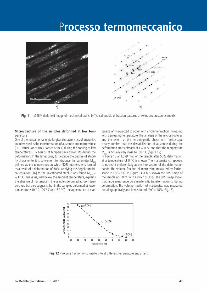
Thermomechanical processingFigure 11a shows a dark-field TEM image of a group of twins inside the grains. As it can be noted, there is a common orienta-tion relationship between the mechanical twins with respect to the matrix. In Figure 11b it can be noted the characteristic double diffraction pattern formed by the superposition of two patterns, the first relating to the matrix and the second with index marked
with a “T” relating to twin with the characteristic misorientation relation of 60°. The un-splitted central spots, characterized by spots T111111 = , T222222 = , etc, are related to the twinning planes {111}. The zone-axis for the two diffraction pat-terns (matrix, twins) are respectively and [110]T.
Fig. 8 - Taylor factor map of the 30% deformed sample.
Fig. 9 - Metallographic measurement of the fraction F of grains with mechanical twins and the fraction f of twins within the grains.
Fig. 10 - TEM image of austenitic grains with an high density of twins f=0,36
La Metallurgia Italiana - n. 3 2017 43
Processo termomeccanico
a) b)
Fig. 11 - a) TEM dark field image of mechanical twins; b) Typical double diffraction patterns of twins and austenitic matrix.
Microstructure of the samples deformed at low tem-perature One of the fundamental metallurgical characteristics of austenitic stainless steel is the transformation of austenite into martensite e (HCP lattice) or a ‘(BCC lattice or BCT) during the cooling at low temperatures (T <Ms) or at temperatures above Ms during the deformation. In the latter case, to describe the degree of stabil-ity of austenite, it is convenient to introduce the parameter Md30 defined as the temperature at which 50% martensite is formed as a result of a deformation of 30%. Applying the Angels empiri-cal equation [16] to the investigated steel it was found Md30 = -21 ° C. This value, well below the ambient temperature, explains the absence of martensite in the samples deformed at room tem-perature but also suggests that in the samples deformed at lower temperatures (0 ° C, -20 ° C and -50 °C) the appearance of mar-
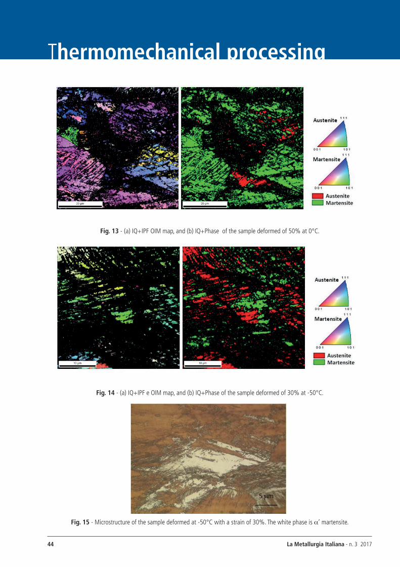
tensite a' is expected to occur with a volume fraction increasing with decreasing temperature. The analysis of the microstructures and the extent of the ferromagnetic phase with ferritoscope clearly confirm that the destabilization of austenite during the deformation starts already at T = 0 °C and that the temperature Md30 is actually very close to -50 ° C (figure 12).In figure 13 an EBSD map of the sample after 50% deformation at a temperature of 0 °C is shown. The martensite a' appears to nucleate preferentially at the intersection of the deformation bands. The volume fraction of martensite, measured by ferrito-scope, is Fa'= 5%. In Figure 14 a-b is shown the EBSD map of the sample at -50 °C with a strain of 30%. The EBSD map shows that large areas undergo a martensitic transformation a' during deformation. The volume fraction of martensite, was measured metallographically and it was found Fa' = 48% (Fig.15).
Fig. 12 - Volume fraction of a’ martensite at different temperature and strain.
La Metallurgia Italiana - n. 3 201744
Thermomechanical processing
Fig. 13 - (a) IQ+IPF OIM map, and (b) IQ+Phase of the sample deformed of 50% at 0°C.
Fig. 14 - (a) IQ+IPF e OIM map, and (b) IQ+Phase of the sample deformed of 30% at -50°C.
Fig. 15 - Microstructure of the sample deformed at -50°C with a strain of 30%. The white phase is a’ martensite.
La Metallurgia Italiana - n. 3 2017 45
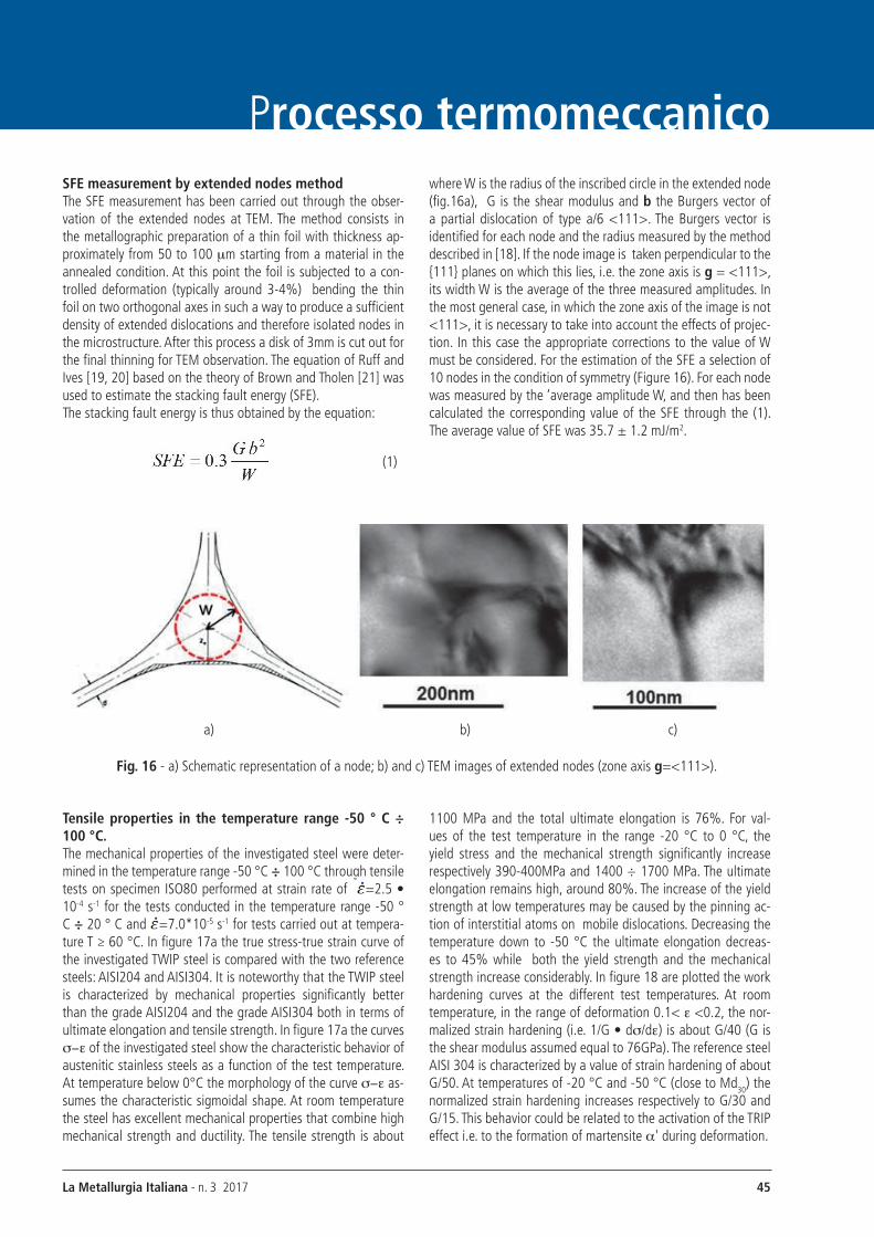
Processo termomeccanicoSFE measurement by extended nodes method The SFE measurement has been carried out through the obser-vation of the extended nodes at TEM. The method consists in the metallographic preparation of a thin foil with thickness ap-proximately from 50 to 100 mm starting from a material in the annealed condition. At this point the foil is subjected to a con-trolled deformation (typically around 3-4%) bending the thin foil on two orthogonal axes in such a way to produce a sufficient density of extended dislocations and therefore isolated nodes in the microstructure. After this process a disk of 3mm is cut out for the final thinning for TEM observation. The equation of Ruff and Ives [19, 20] based on the theory of Brown and Tholen [21] was used to estimate the stacking fault energy (SFE). The stacking fault energy is thus obtained by the equation:
(1)
where W is the radius of the inscribed circle in the extended node (fig.16a), g is the shear modulus and b the Burgers vector of a partial dislocation of type a/6 <111>. The Burgers vector is identified for each node and the radius measured by the method described in [18]. If the node image is taken perpendicular to the {111} planes on which this lies, i.e. the zone axis is g = <111>, its width W is the average of the three measured amplitudes. In the most general case, in which the zone axis of the image is not <111>, it is necessary to take into account the effects of projec-tion. In this case the appropriate corrections to the value of W must be considered. For the estimation of the SFE a selection of 10 nodes in the condition of symmetry (Figure 16). For each node was measured by the ‘average amplitude W, and then has been calculated the corresponding value of the SFE through the (1). The average value of SFE was 35.7 ± 1.2 mJ/m2.
a) b) c)
Fig. 16 - a) Schematic representation of a node; b) and c) TEM images of extended nodes (zone axis g=<111>).
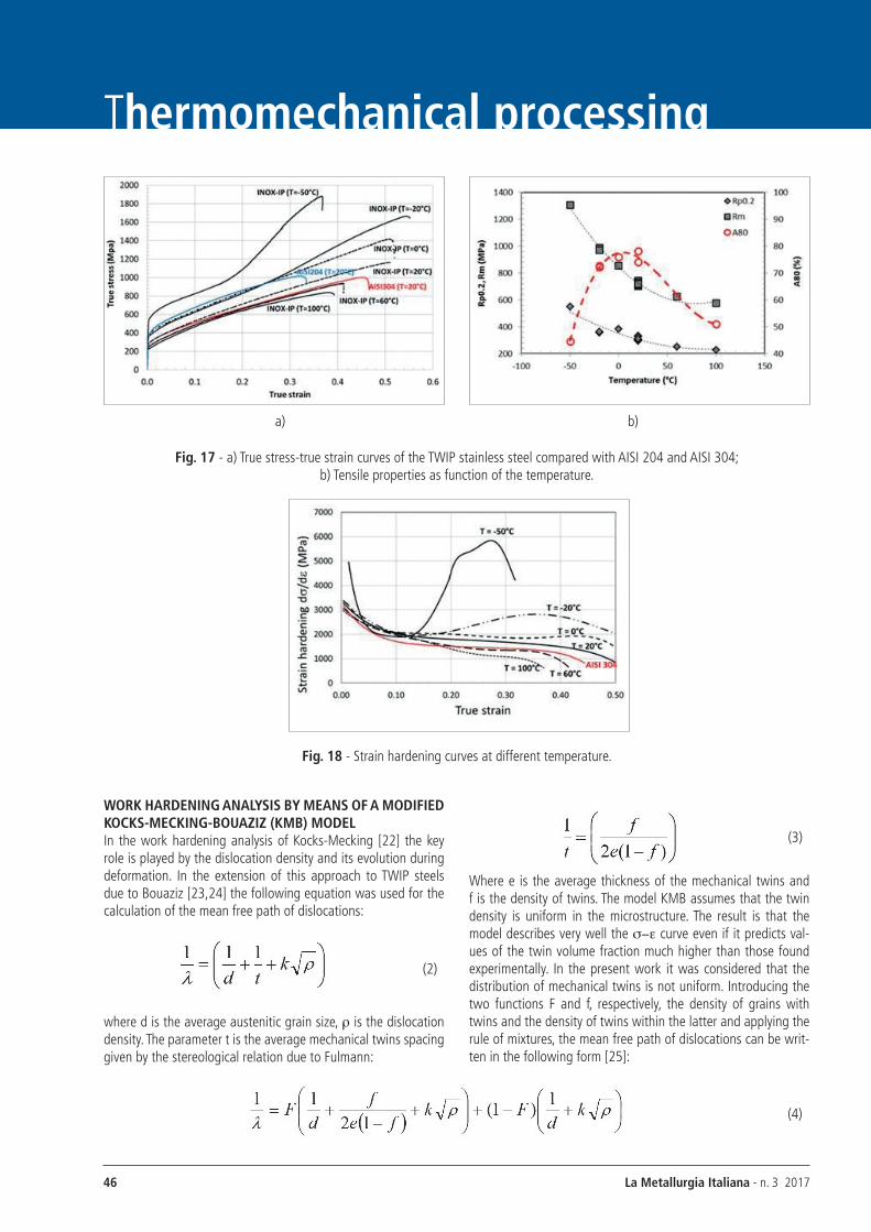
Tensile properties in the temperature range -50 ° C ÷ 100 °C.The mechanical properties of the investigated steel were deter-mined in the temperature range -50 °C ÷ 100 °C through tensile tests on specimen ISO80 performed at strain rate of =2.5 • 10-4 s-1 for the tests conducted in the temperature range -50 ° C ÷ 20 ° C and =7.0*10-5 s-1 for tests carried out at tempera-ture T ≥ 60 °C. In figure 17a the true stress-true strain curve of the investigated TWIP steel is compared with the two reference steels: AISI204 and AISI304. It is noteworthy that the TWIP steel is characterized by mechanical properties significantly better than the grade AISI204 and the grade AISI304 both in terms of ultimate elongation and tensile strength. In figure 17a the curves s-e of the investigated steel show the characteristic behavior of austenitic stainless steels as a function of the test temperature. At temperature below 0°C the morphology of the curve s-e as-sumes the characteristic sigmoidal shape. At room temperature the steel has excellent mechanical properties that combine high mechanical strength and ductility. The tensile strength is about
1100 MPa and the total ultimate elongation is 76%. For val-ues of the test temperature in the range -20 °C to 0 °C, the yield stress and the mechanical strength significantly increase respectively 390-400MPa and 1400 ÷ 1700 MPa. The ultimate elongation remains high, around 80%. The increase of the yield strength at low temperatures may be caused by the pinning ac-tion of interstitial atoms on mobile dislocations. Decreasing the temperature down to -50 °C the ultimate elongation decreas-es to 45% while both the yield strength and the mechanical strength increase considerably. In figure 18 are plotted the work hardening curves at the different test temperatures. At room temperature, in the range of deformation 0.1< e <0.2, the nor-malized strain hardening (i.e. 1/g • ds/de) is about g/40 (g is the shear modulus assumed equal to 76gPa). The reference steel AISI 304 is characterized by a value of strain hardening of about g/50. At temperatures of -20 °C and -50 °C (close to Md30) the normalized strain hardening increases respectively to g/30 and g/15. This behavior could be related to the activation of the TRIP effect i.e. to the formation of martensite a' during deformation.
La Metallurgia Italiana - n. 3 201746
Thermomechanical processing
a) b)
Fig. 17 - a) True stress-true strain curves of the TWIP stainless steel compared with AISI 204 and AISI 304; b) Tensile properties as function of the temperature.
Fig. 18 - Strain hardening curves at different temperature.
WORK hARDENINg ANALYSIS bY MEANS OF A MODIFIED KOCKS-MECKINg-bOUAzIz (KMb) MODELIn the work hardening analysis of Kocks-Mecking [22] the key role is played by the dislocation density and its evolution during deformation. In the extension of this approach to TWIP steels due to Bouaziz [23,24] the following equation was used for the calculation of the mean free path of dislocations:
(2)
where d is the average austenitic grain size, r is the dislocation density. The parameter t is the average mechanical twins spacing given by the stereological relation due to Fulmann:
(3)
Where e is the average thickness of the mechanical twins and f is the density of twins. The model KMB assumes that the twin density is uniform in the microstructure. The result is that the model describes very well the s-e curve even if it predicts val-ues of the twin volume fraction much higher than those found experimentally. In the present work it was considered that the distribution of mechanical twins is not uniform. Introducing the two functions F and f, respectively, the density of grains with twins and the density of twins within the latter and applying the rule of mixtures, the mean free path of dislocations can be writ-ten in the following form [25]:
(4)

La Metallurgia Italiana - n. 3 2017 47
Processo termomeccanicoOn the basis of the metallographic measurement of the twin vol-ume fraction as a function of interrupted strain (figure 9) it was assumed that the ratio f/F can be considered constant for which
the volumetric fractions of twins can be defined as follows [23, 24]:
(5)
where the parameter m is a function of the energy of the stack-ing fault and strain rate, fo and Fo are the saturation values and are assumed equal to 0.2 and 1. From the equations (5) it can be seen that the parameter m is the parameter controlling the
kinetics of mechanical twins nucleation. Following the approach described in [25] the change in the dislocation density can be written:
(6)
where M is the Taylor factor, k (dislocation hardening), a (dy-namic recovery) and m (twin nucleation rate) are the three pa-rameters of the model. Once integrated numerically the equation (6) and replaced the dislocation density in the Taylor equation [27], the function s(e) is obtained. The values of the parameters
are determined by the least squares method applied between the s(e) and experimental s-e curves. In Figure 19 are compared the theoretical s-e curves with the experimental s-e curves and as it can be noted the agreement is very good.
Fig. 19 - Comparison between the experimental true stress-true strain curves with the curves calculated with the modified KMB model.
The values of the model parameters, shown in Table 2, were cal-culated considering a critical value of deformation (ec = 0.08) above which starts the formation of mechanical twins.
Tab.2 - Model parameter for the stainless TWIP steel at the different test temperature.
T (°C) m a k
0 3 0.15 0.017
20 4.4 0.75 0.017
60 3.9 1.3 0.017
100 1.1 2.0 0.017
In Figure 20 is shown the evolution of the volume fraction of grains with twins as a function of the deformation calculated from the equation (5). As it can be noted the agreement with the experimental data is quite good.
Fig. 20 - Volume fraction of grains with twins as a function of the strain at the different test temperature. The dots represent
the measured volume fraction at room temperature.
The analysis by means of KMB work hardening model allowed to obtain a description of the TWIP effect as a function of tempera-ture within the range SFEmin-SFEmax by means of the parameter m. Table 2 shows the values of the parameter m calculated on the basis of the curves s-e, as a function of test temperature. As it can be noted the parameter m is a function of both the temperature and the SFE and shows a maximum in correspond-

La Metallurgia Italiana - n. 3 201748
Thermomechanical processingence of the ambient temperature. This result allowed to conclude that the investigated TWIP stainless steel is characterized by a maximum mechanical twins nucleation (maximum TWIP effect) at about 20 °C.The results reported in table 2 indicated that the higher work hardening rate below the room temperature could be due to lower dynamic recovery and the occurrence of the TRIP effect. Above the room temperature, a downward trend of work hard-ening rate is observed and this could be explained by the simul-taneous increase of the dynamic recovery (lower forest disloca-tion density) and the decrease of the parameter m. These two factors determine the decrease in the ductility of steel TWIP steel with increasing temperature.
CONCLUSIONS The present work demonstrated that the mechanical properties of low nickel austenitic stainless steels can be significantly im-proved thanks to the TWIP effect. The investigated steel Fe-17Cr-8Mn-Ni-Cu is characterized by a microstructure consisting of austenite with a low SFE which pro-motes the nucleation of mechanical twins during deformation.EBSD observation shown that, coherently with what already ob-served in high-Mn TWIP steel, the mechanical twin nucleation is triggered by high Taylor factor grains, where dislocation glide is difficult. The mechanical twins significantly increase the strain hardening thanks to dynamic Hall-Petch effect, improving significantly the mechanical strength and ductility.The characterization of work hardening in a wide temperature range allowed establishing that the TWIP behavior is predomi-nant in the temperature range 0 °C to 100 °C. For temperatures below 0 °C, the austenite is unstable during the deformation and as the temperature decreases an increasing TRIP effect is activated. Within the temperature interval in which deformation is assisted by TWIP and TRIP effect (-20 ° C to 100 ° C) the me-chanical properties are excellent in terms of ultimate elongation and tensile strength. The new stainless TWIP steel is character-ized by an energy absorption comparable to that of the high-Mn TWIP steel. For the investigated steel a wider applicability can be envisaged not only for automotive components with increased crashworthiness, but also for production of high demanding products, for which the corrosion resistance together with me-chanical properties and good forming ability are the main as-pects leading the product design.
REFERENCES[1] Chateau and Bouaziz, O., 2004, Materials Science and
Engineering A, 387-389, pp.143-147.[2] gutierrez-urrutia, D. Raabe, Acta Mater. 59 (2011) 6449.[3] A. Ferraiuolo, Austenitic TWIP stainless steel, its produc-
tion and use, EP 2935640 A2. [4] Scott, S. Allain, M. Faral, N. guelton, Revue de Metallur-
gie, 103 (6), pp.293-302.
[5] M.A. Meyers, O. Vohringer, Acta Met-., 49, 2001, 4025-4039.
[6] Pickering, F.B.: g.l. Dunlop (Ed.), Stainless Steels 84. Chalmers university of Technology, göteborg, 3-4 Sep-tember, 1984, The Institute of Metals, london, 1985, p. 12.
[7] Schramm RE, Reed RP. Metall Trans A 1975;6:1345. [8] Rhodes Cg, Thompson AW. Metall Trans A 1977;8:1901. [9] linda Mosecker and Alireza Saeed-Akbari Sci. Technol.
Adv. Mater. 14 (2013) 033001.[10] A. Ferraiuolo, et al., Metallurgical design of high-strength
austenitic Fe-C-Mn steels with excellent formability (Met-aldesign), Contract No RFSR-CT-2005-00030.
[11] F. de las Cuevas, A. Ferraiuolo, g. Pratolongo, l.P. Kar-jalainen, V. garcía Navas, J. gil Sevillano, M. Reis,: Adv. Mat. Res. Vols. 89-91 (2010) pp 153-158. Wang, Kun Wang, Fusheng Han Philosophical Magazine letters Vol-ume 93, Issue 5, 2013.
[12] Xianfeng D, Dan Wanga, Kun Wanga Fusheng Han; Phil-osophical Magazine letters Volume 93, Issue 5, 2013 pages 316-321.
[13] R. Marceau, I. gutierrez-urrutia,1 M. Herbig,K. Moore, S. lozano-Perez, D. Raabe; Microsc. Microanal. August 2013, P.1-5.
[14] gutierrez-urrutia, I. , Raabe, D.; Acta Mater 59, 2011, 6449–6462.
[15] gutierrez-urrutia, I. ,Zaefferer, S., and Raabe, D., 2010, Materials Science and Engineering A, 527 (15), pp.3552-3560. effect of grain size and grain orientation on defor-mation twinning in a Fe–22 wt.% Mn–0.6 wt.% C TWIP steel
[16] Angel, T.: “Formation of martensite in austenitic stainless steels”, J.Iron and Steel Inst., london, 177, 1954, p. 165-174.
[17] T. Ericsson, Acta Met. 14, 853 (1966).[18] l. Remy, Acta Met.,vol 25 pp.173-179, 1977[19] A.W. Ruff, l. K. Ives, Acta Met. Vol 15, 1967 189-198.[20] M. J. Whelan, Proc. Roy. Soc. A249, p.114-118 (1959).[21] l. M. Brown, A. R. Tholen, Discuss. Faraday Soc. 38, 35
(1964).[22] u. F. Kocks, H Mecking, Progr. Mat. Scie., vol 48 2003 p.
171.[23] Bouaziz O, guelton N. Materials Science and Engineer-
ing: A 2001; 319-321. [24] g.B. Olson and M. Cohen, Kinetics of strain-induced
martensitic nucleation, Metall. Trans. 6A (1975), pp. 791–795.
[25] A.Ferraiuolo, New stainless steel characterised by excel-lent plasticity, Proc. Conference HMnS2nd Aachen, 2014, p.71-74.
[26] Olson gB, Cohen M.,Metall Trans A, 1976;7:1905. [27] Taylor gI. Proc Roy Soc 1934;A145:362.