new si techniques for large system performance...
TRANSCRIPT

TITLE
Image
New SI Techniques for
Large System Performance Tuning
Donald Telian, SiGuys
Michael Steinberger, SiSoft
Authors: Donald Telian (SiGuys), Michael Steinberger, Barry Katz (SiSoft)

SPEAKERS Donald Telian
Signal Integrity Consultant / Owner, SiGuys
[email protected], www.siguys.com
Donald Telian is an independent Signal Integrity Consultant and Owner of SiGuys. Building on over 30
years of SI experience at Intel, Cadence, HP, and others, his recent focus has been on helping customers
correctly implement today’s Multi-Gigabit serial links. His numerous published works on this and other
topics are available at his website www.siguys.com. Donald is widely known as the SI designer of the
PCI bus and the originator of IBIS modeling and has taught SI techniques to thousands of engineers in
more than 15 countries.
Michael Steinberger
Lead Architect, SiSoft
[email protected] | www.sisoft.com
Michael Steinberger, Ph.D., Lead Architect for SiSoft, has over 30 years’ experience designing very high
speed electronic circuits. Dr. Steinberger holds a Ph.D. from the University of Southern California and has
been awarded 14 patents. He is currently responsible for the architecture of SiSoft's Quantum Channel
Designer tool for high speed serial channel analysis. Before joining SiSoft, Dr. Steinberger led a group at
Cray, Inc. performing SerDes design, high speed channel analysis, PCB design and custom RAM design.

• Introduction
• Co-Optimization
• Discontinuities
• Summary
AGENDA: New SI Techniques
Large System Performance
Tuning

• 4th in a Series of Papers
• Large System Design
– Thousands of Serial Links
• Correlated System Model
• Systems, Techniques, Learnings
BACKGROUND
red = measured green = simulated
Channel TDR
BER

• Introduction
• Co-Optimization
– Problem
– Improvement
– Technique
• Discontinuities
• Summary
AGENDA
Large System Performance
Tuning

• New cards, newer SerDes, extends channel length
• Can older SerDes succeed? …is a Re-Timer needed?
Equalization Co-Optimization Scenario
Original Channel Extension
NEW OLD
A
B
Re-Timer?

• Best-known EQ
– Gold/black channels up to 25% too long
– Eye height fails with extended lengths
• Automated Co-Optimized EQ
– 60%+ gains in eye height and width
– All channels above line
– New settings derived
– Re-timers not needed
Applying Co-Optimization

• Many systems, card choices, permutations to verify
• Thousands of scenarios tested, refinements to algorithms
More Systems, More Testing
Blue = Best known EQ Red = Co-Optimized EQ
large medium small

System Equalization Co-Optimization
Optimization Concepts Engineering Judgement
1. Recover Clock 2. Minimize Intersymbol Interference 3. Equalization Tradeoffs
1
2
3 4
Tx FFE

“Hula Hoop” Algorithm Find median threshold crossing time 1. Drop a one UI diameter hoop
onto pulse response 2. Where hoop is level, hoop touches
pulse at the edges of the eye
1 UI
Centered
Note: Equalization affects the recovered clock; so adjust the sampling time after equalizing the pulse.
Recovered Clock Time

Estimate Earliest Tap Weight
V(-1)
V(0)
𝑊 −1 = −𝑉(−1)
𝑉 −1 + 𝑉(0)
𝑊 0 = 𝑉(0)
𝑉 −1 + 𝑉(0)
Clo
ck R
eco
very
Clo
ck R
eco
very
Unequalized
Precursor Tap
Equalized by Precursor
Clo
ck R
eco
very
Clo
ck R
eco
very
Precursor ISI canceled out

Estimate Next Tap Weight
Unequalized
Precursor Tap
Equalized Postcursor Tap
Clo
ck R
eco
very
Clo
ck R
eco
very
V(-1)
V(0)
V’(1)
𝑊 −1 ≈ −𝑉(−1)
𝑉 −1 + 𝑉 0 + 𝑉′(1)
𝑊 0 ≈𝑉(0)
𝑉 −1 + 𝑉 0 + 𝑉′(1)
𝑊 −1 ≈ −𝑉′(1)
𝑉 −1 + 𝑉 0 + 𝑉′(1) C
lock
Rec
ove
ry
Clo
ck R
eco
very
V(1)
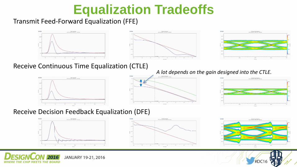
Transmit Feed-Forward Equalization (FFE)
Receive Continuous Time Equalization (CTLE)
Receive Decision Feedback Equalization (DFE)
A lot depends on the gain designed into the CTLE.
Equalization Tradeoffs

DFE vs. FFE Tx FFE Tap -1 and Tap 1
Tx FFE Tap -1 and Tap 2 + Rx DFE Tap 1
Unequalized Precursor Tap
Equalized Postcursor Tap 2
Postcursor Tap 1
Rx DFE Tap 1 + Tx FFE Tap 2
DFE more main pulse amplitude
Very similar equalization
FFE Tap -1
FFE Tap 1
Tx FFE Tap 1
Replaced by
FFE Tap -1
FFE Tap 2
DFE Tap 1
or DFE Tap 1

Tradeoff EQ to Optimize Performance FFE, CTLE, and DFE can each equalize the channel.
Choose the combination that maximizes performance margin. Amplitude at decision point (eye height)
Equalize multiple bit positions per tap/configuration
Equalize for bits not yet transmitted (pre-cursor tap)
FFE Reduces amplitude Yes Yes
CTLE May help or hurt. (depends on design).
Yes No
DFE No impact No No (except digital designs)
?
Precursor Main Response Clean-up
Automated Co-Optimization Too complex for time available.

• Problem:
– Long/lossy channel
– 4-tap Tx (1pre, 2post)
– No Rx EQ
• Manual Technique (blue)
– Force zero in all taps
• Co-Optimization (red)
– Trade amplitude for ISI
– 15% better eye
Automation Example
blue red

• Introduction
• Co-Optimization
• Discontinuities
– Design/Process Control
– Dual-Diameter Vias
– Trace Compensation
• Summary
AGENDA
Large System Performance
Tuning
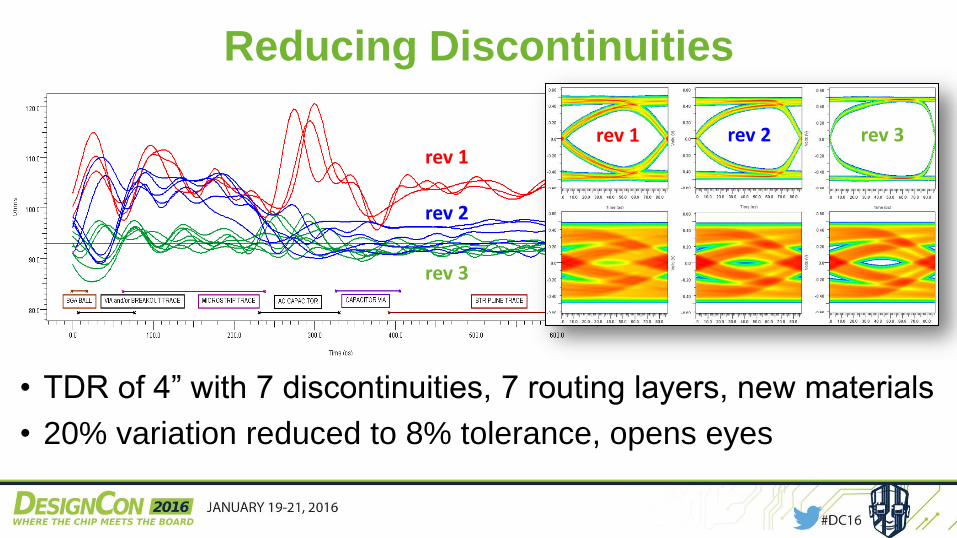
• TDR of 4” with 7 discontinuities, 7 routing layers, new materials
• 20% variation reduced to 8% tolerance, opens eyes
Reducing Discontinuities
rev 1
rev 2
rev 3
rev 1 rev 2 rev 3

• Measured Improvement:
+20 Ohms (30%)
• TDR shows: channel
discontinuity-induced-
resonance removed
• Eye Openings: 30%
improvement
Dual-Diameter Vias D-d via
Normal via
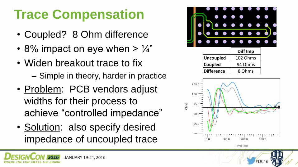
• Coupled? 8 Ohm difference
• 8% impact on eye when > ¼”
• Widen breakout trace to fix
– Simple in theory, harder in practice
• Problem: PCB vendors adjust
widths for their process to
achieve “controlled impedance”
• Solution: also specify desired
impedance of uncoupled trace
Trace Compensation
Diff Imp
Uncoupled 102 Ohms
Coupled 94 Ohms
Difference 8 Ohms
• Introduction
• Co-Optimization
• Discontinuities
• Summary
AGENDA
Large System Performance
Tuning

• New SI Techniques for Tuning Performance
• SerDes Equalization Co-Optimization
– Automated solution increases design space & margin
• Performance gains of 60%+ demonstrated
• No hardware change required (firmware only)
• Impedance Discontinuity Reduction
– Manufacturing methods combined with measurement reduce ISI
• Performance gains of 30%+ demonstrated
SUMMARY

• More Optimization Detail: Tomorrow 9:20 – 10am, Mission City M2
“A SerDes Balancing Act: Co-Optimizing TX and RX Equalization Settings to Maximize Margin”
• SiSoft Booth on Exhibition Floor: Booth #935, “Beat the Co-Optimizer?!”
• All Papers in Series: http://www.siguys.com/published.html, http://www.sisoft.com/elearning
• Authors: [email protected] [email protected] [email protected]
• Websites: www.siguys.com, www.sisoft.com
FOR MORE INFORMATION

TITLE
Image ---
QUESTIONS?
Thank You!