new products guided cylinder - bibus · 2011-04-19 · guided cylinder stg series guided cylinder...
TRANSCRIPT
GUIDED CYLINDERSTG SERIES
GUIDED CYLINDER STG SERIES
CC-781A 2
New Products
High Precision/High rigidityEcological
Additional variation
New eco-friendly guided cylinder
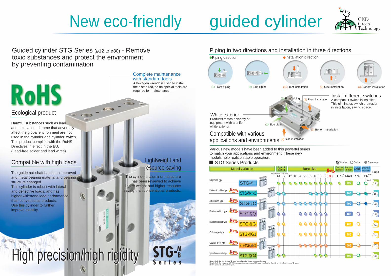
Guided cylinder STG Series (ø12 to ø80) - Removetoxic substances and protect the environmentby preventing contamination
Ecological product
Harmful substances such as leadand hexavalent chrome that adverselyaffect the global environment are notused in the cylinder and cylinder switch.This product complies with the RoHSDirectives in effect in the EU.(Lead-free solder and lead wires)
Compatible with variousapplications and environmentsVarious new models have been added to this powerful seriesto match your applications and environment. These newmodels help realize stable operation.
Compatible with high loads
The guide rod shaft has been improvedand metal bearing material and bearingstructure changed.This cylinder is robust with lateraland deflective loads, and hashigher withstand load performancethan conventional products.Use this cylinder to furtherimprove stability.
Lightweight andresource-saving
The cylinder's aluminum structurehas been reviewed to achieve
lighter weight and higher resourcesaving than conventional products.
High precision/high rigidityHigh precision/high rigidity
Piping in two directions and installation in three directionsPiping direction Installation direction
(1) Front piping
(1) Front piping
(2) Side piping
(2) Side piping
(1) Front installation
(1) Front installation
(2) Side installation
(2) Side installation
(3) Bottom installation
(3) Bottom installation
Install different switchesA compact T switch is installed.This eliminates switch protrusionin installation, saving space.
White exteriorProducts match a variety ofequipment with a uniformwhite exterior.
Complete maintenancewith standard toolsA hexagon wrench is used to installthe piston rod, so no special tools arerequired for maintenance.
STG Series ProductsModel variation Bore size SwitchType of
bearingClean roomspecification
Max. strokelength
copper andPTFE freespecifications
Standard Option Custom order
Page
Single rod type
Rubber-air cushion type
Air cushion type
Position locking type
Rubber scraper type
Coil scraper type
Coolant proof type
Spatter adherence prevention type
Metal bush bearing Ball bearing Note 1 Note 2
Note 3
Note 1: Only the ball bearing "B type" is available for clean room specifications.Note 2: Only the copper and PTFE free specifications are available as a standard for the ø12 to ø32 rolling bearing "B type".Note 3: ø80 is a custom order part.
STG-MG2,MG3
STG- G4MB
STG- G1MB
STG- GMB
STG- QMB
STG- CMB
STG- -*-CMB
STG-MB
M B 16 20 25 32 40 50 63 P7 P6
3
15
23
33
41
41
47
53
MAX SW8012
Intro 1
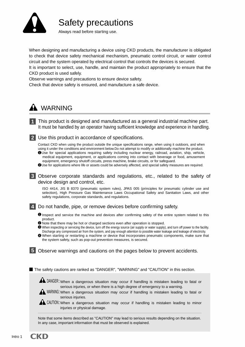
Safety precautionsAlways read before starting use.
1
2
3
4
5
1
23
4
DANGER:
WARNING:
CAUTION:
WARNING
When designing and manufacturing a device using CKD products, the manufacturer is obligated to check that device safety mechanical mechanism, pneumatic control circuit, or water control circuit and the system operated by electrical control that controls the devices is secured.It is important to select, use, handle, and maintain the product appropriately to ensure that the CKD product is used safely.Observe warnings and precautions to ensure device safety.Check that device safety is ensured, and manufacture a safe device.
This product is designed and manufactured as a general industrial machine part.It must be handled by an operator having sufficient knowledge and experience in handling.
Use this product in accordance of specifications.
Observe corporate standards and regulations, etc., related to the safety of device design and control, etc.
Observe warnings and cautions on the pages below to prevent accidents.
Do not handle, pipe, or remove devices before confirming safety.
1
2
Contact CKD when using the product outside the unique specifications range, when using it outdoors, and when using it under the conditions and environment below.Do not attempt to modify or additionally machine the product.
Use for special applications requiring safety including nuclear energy, railroad, aviation, ship, vehicle, medical equipment, equipment, or applications coming into contact with beverage or food, amusement equipment, emergency shutoff circuits, press machine, brake circuits, or for safeguard.Use for applications where life or assets could be adversely affected, and special safety measures are required.
Inspect and service the machine and devices after confirming safety of the entire system related to this product.Note that there may be hot or charged sections even after operation is stopped.When inspecting or servicing the device, turn off the energy source (air supply or water supply), and turn off power to the facility. Discharge any compressed air from the system, and pay enough attention to possible water leakage and leakage of electricity.When starting or restarting a machine or device that incorporates pneumatic components, make sure that the system safety, such as pop-out prevention measures, is secured.
ISO 4414, JIS B 8370 (pneumatic system rules), JPAS 005 (principles for pneumatic cylinder use and selection), High Pressure Gas Maintenance Laws Occupational Safety and Sanitation Laws, and other safety regulations, corporate standards, and regulations.
When a dangerous situation may occur if handling is mistaken leading to fatal or serious injuries, or when there is a high degree of emergency to a warning.
When a dangerous situation may occur if handling is mistaken leading to fatal or serious injuries.
When a dangerous situation may occur if handling is mistaken leading to minor injuries or physical damage.
Note that some items described as "CAUTION" may lead to serious results depending on the situation.In any case, important information that must be observed is explained.
The safety cautions are ranked as "DANGER", "WARNING" and "CAUTION" in this section.
Intro 2
Pneumatic components
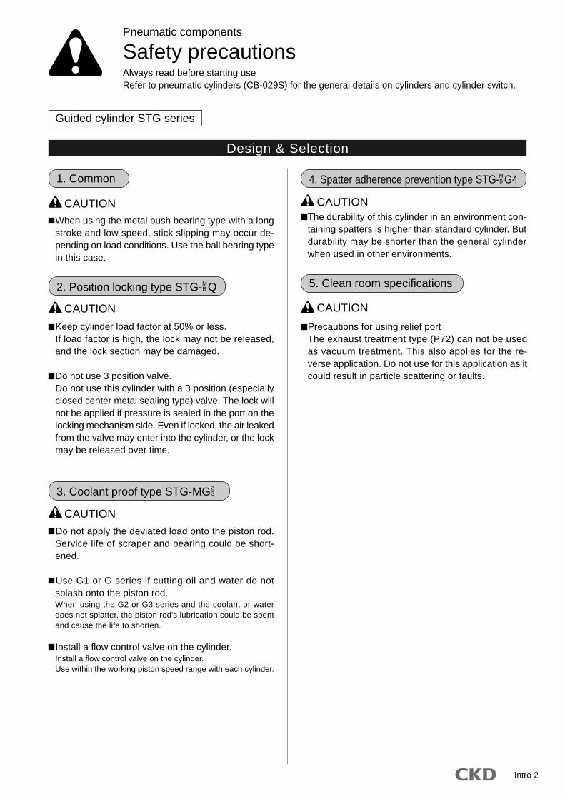
Safety precautionsAlways read before starting useRefer to pneumatic cylinders (CB-029S) for the general details on cylinders and cylinder switch.
Guided cylinder STG series
When using the metal bush bearing type with a longstroke and low speed, stick slipping may occur de-pending on load conditions. Use the ball bearing typein this case.
CAUTION
Design & Selection
Keep cylinder load factor at 50% or less. If load factor is high, the lock may not be released,
and the lock section may be damaged.
Do not use 3 position valve. Do not use this cylinder with a 3 position (especially
closed center metal sealing type) valve. The lock willnot be applied if pressure is sealed in the port on thelocking mechanism side. Even if locked, the air leakedfrom the valve may enter into the cylinder, or the lockmay be released over time.
2. Position locking type STG-M B Q
CAUTION
Do not apply the deviated load onto the piston rod.Service life of scraper and bearing could be short-ened.
Use G1 or G series if cutting oil and water do notsplash onto the piston rod.When using the G2 or G3 series and the coolant or waterdoes not splatter, the piston rod's lubrication could be spentand cause the life to shorten.
Install a flow control valve on the cylinder.Install a flow control valve on the cylinder.Use within the working piston speed range with each cylinder.
3. Coolant proof type STG-MG2 3
CAUTION
CAUTION
4. Spatter adherence prevention type STG-M B G4
The durability of this cylinder in an environment con-taining spatters is higher than standard cylinder. Butdurability may be shorter than the general cylinderwhen used in other environments.
Precautions for using relief portThe exhaust treatment type (P72) can not be usedas vacuum treatment. This also applies for the re-verse application. Do not use for this application as itcould result in particle scattering or faults.
5. Clean room specifications
CAUTION
1. Common
Intro 3
Installation & Adjustment
STG Series
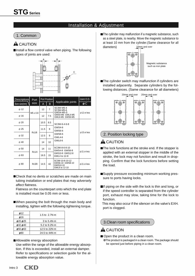
Install a flow control valve when piping. The followingtypes of joints are used:
CAUTION
C
A B
Descriptions
Bore size(mm)Applicable joints
Port PositionPortsize
M5 x 0.8
Rc1/8
SC3W-M5-4SC3W-M5-6GWS4-M5-SGWS4-M5 GWL4-M5GWL6-M5 GWS6-M5
SC3W-6-4·6·8GWS4-6GWS6-6GWS8-6GWL4-6GWL6-6
12 or less
Joint O.D.
C
15 or less
12
12
10.5
11.5
12.5
14
14
16.5
14.5
A B
7
7.5
8.5
9
9
10
11
15
42
12
16
20
25
32
40
50
63
80
Rc1/4
Rc3/8
SC3W-8-6·8·10GWS4-8 GWS6-8GWS10-8 GWS12-8GWL4 to 12-8
SC3W-10-8·10·12GWS6-10 GWS8-10GWS10-10GWL6 to 12-10
21 or less
21 or less
Check that no dents or scratches are made on maintubing installation or end plates that may adverselyaffect flatness.Flatness on the counterpart onto which the end plateis installed must be 0.05 mm or less.
When passing the bolt through the main body andinstalling, tighten with the following tightening torque.
Allowable energy absorptionUse within the range of the allowable energy absorp-tion. If this is exceeded, install an external damper.Refer to specifications or selection guide for the al-lowable energy absorption value.
1. Common
12
16
20, 25
32, 40
50, 63
80
1.5 to 2.7N·m
3 to 5.4N·m
5.2 to 9.2N·m
12.5 to 22N·m
24.5 to 44N·m
The cylinder may malfunction if a magnetic substance, suchas a steel plate, is nearby. Move the magnetic substance toat least 10 mm from the cylinder.(Same clearance for alldiameters)
The cylinder switch may malfunction if cylinders areinstalled adjacently. Separate cylinders by the fol-lowing distances. (Same clearance for all diameters)
10mm and over
Magnetic substancesuch as iron plate
20mm and over 20mm and over
The lock functions at the stroke end. If the stopper isapplied with an external stopper in the middle of thestroke, the lock may not function and result in drop-ping. Confirm that the lock functions before settingthe load.
Supply pressure exceeding minimum working pres-sure to ports having locks.
If piping on the side with the lock is thin and long, orif the speed controller is separated from the cylinderport, exhaust may slow, taking time for the lock tofunction.
This may also occur if the silencer on the valve's EXH.port is clogged.
2. Position locking type
CAUTION
Open the product in a clean room.The product is packaged in a clean room. The package shouldbe opened just before piping in a clean room.
CAUTION
3.Clean room specifications
Intro 4
During use & Maintenance
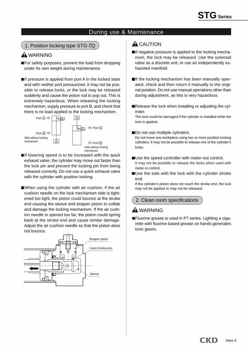
1. Position locking type STG- M B Q
WARNING
For safety purposes, prevent the load from droppingunder its own weight during maintenance.
If pressure is applied from port A in the locked stateand with neither port pressurized, it may not be pos-sible to release locks, or the lock may be releasedsuddenly and cause the piston rod to pop out. This isextremely hazardous. When releasing the lockingmechanism, supply pressure to port B, and check thatthere is no load applied to the locking mechanism.
If lowering speed is to be increased with the quickexhaust valve, the cylinder may move out faster thanthe lock pin and prevent the locking pin from beingreleased correctly. Do not use a quick exhaust valvewith the cylinder with position locking.
When using the cylinder with air cushion, if the aircushion needle on the lock mechanism side is tight-ened too tight, the piston could bounce at the strokeend causing the sleeve and stopper piston to collideand damage the locking mechanism. If the air cush-ion needle is opened too far, the piston could springback at the stroke end and cause similar damage.Adjust the air cushion needle so that the piston doesnot bounce.
W
WPort
Port
Side without lockingmechanism
Port
PortSide without lockingmechanism
A
B
A
B
Contact of holding section
Stopper piston
Sleeve
Bouncing phenomenon
CAUTION
If negative pressure is applied to the locking mecha-nism, the lock may be released. Use the solenoidvalve as a discrete unit, or use an independently ex-hausted manifold.
If the locking mechanism has been manually oper-ated, check and then return it manually to the origi-nal position. Do not use manual operations other thanduring adjustment, as this is very hazardous.
Release the lock when installing or adjusting the cyl-inder.The lock could be damaged if the cylinder is installed while the
lock is applied.
Do not use multiple cylinders.Do not move one workpiece using two or more position lockingcylinders. It may not be possible to release one of the cylinder's
locks.
Use the speed controller with meter-out control.It may not be possible to release the locks when used with
meter-in control.
Use the side with the lock with the cylinder strokeend.If the cylinder's piston does not reach the stroke end, the lockmay not be applied or may not be released.
Fluorine grease is used in P7 series. Lighting a ciga-rette with fluorine-based grease on hands generatestoxic gases.
2. Clean room specifications
STG Series
WARNING
Seriesvariation
1 2
STG-
STG- -*C
STG- Q
STG- GSTG- G1
STG-MG2STG-MG3
STG- G4
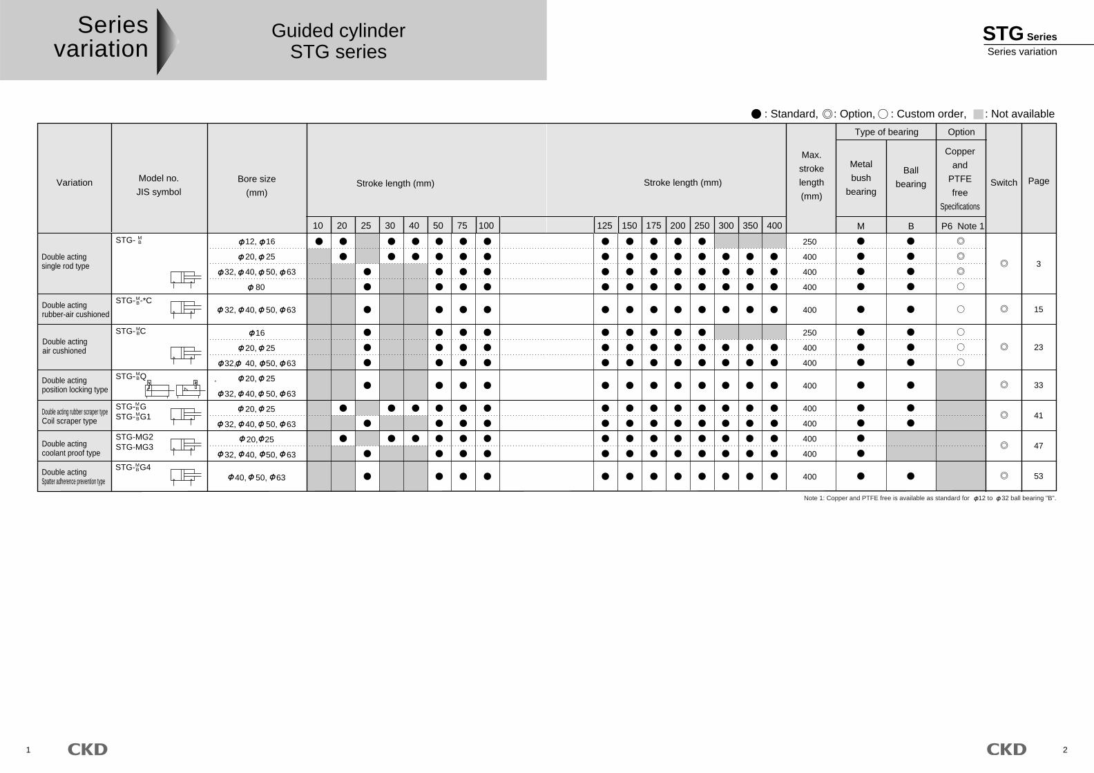
Variation Stroke length (mm)Model no.
JIS symbol
2510 20 30 40 50 75 100
Bore size
(mm)
12, 16
20, 25
32, 40, 50, 63
80
32, 40, 50, 63
16
20, 25
32, 40, 50, 63
20, 25
32, 40, 50, 63
20, 25
32, 40, 50, 63
20, 25
32, 40, 50, 63
40, 50, 63
Double acting rubber scraper typeCoil scraper type
Double actingrubber-air cushioned
Double actingair cushioned
Double actingposition locking type
Double actingcoolant proof type
Double actingSpatter adherence prevention type
Double actingsingle rod type
STG- C
MB
MB
MB
MB
MBMB
MB
Guided cylinderSTG series
Note 1: Copper and PTFE free is available as standard for 12 to 32 ball bearing "B".
Stroke length (mm)
175150 200 250 300 350 400 M B P6
Type of bearing Option
Metal
bush
bearing
Max.
stroke
length
(mm)
Ball
bearing
Copper
and
PTFE
free
Specifications
Switch Page
125
: Standard, : Option, : Custom order, : Not available
250
400
400
400
400
250
400
400
400
400
400
400
400
400
Note 1
3
15
23
33
41
47
53
STG SeriesSeries variation
3
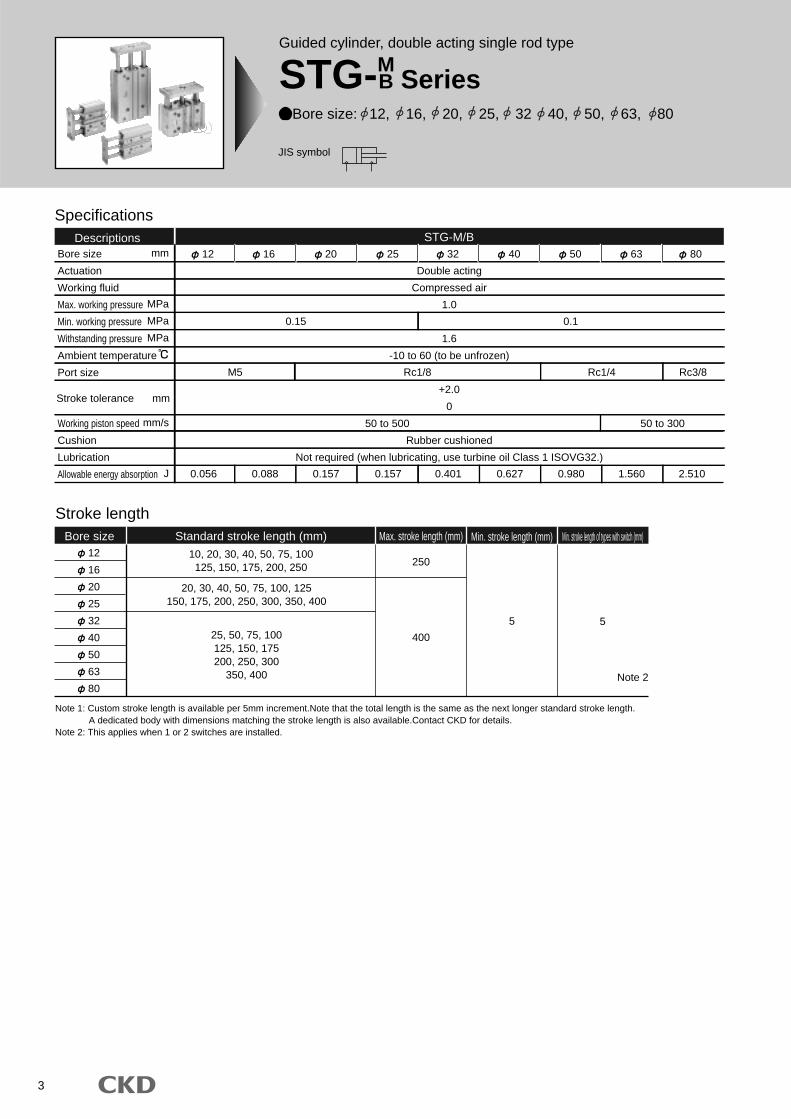
Specifications
Bore size
Actuation
Working fluid
Max. working pressure
Min. working pressure
Withstanding pressure
Ambient temperature
Port size
Working piston speed
Cushion
Lubrication
Allowable energy absorption
Double acting
Compressed air
1.0
1.6
-10 to 60 (to be unfrozen)
+2.0
0
Rubber cushioned
Not required (when lubricating, use turbine oil Class 1 ISOVG32.)
0.15
M5
0.056 0.088 0.157 0.157 0.401 0.627 0.980 2.5101.560
Rc1/8 Rc1/4 Rc3/8
50 to 500 50 to 300
0.1
Descriptions12 16 20 25 32 40 50 63 80
STG-M/B
Stroke length
12
16
20
25
32
40
50
63
80
10, 20, 30, 40, 50, 75, 100125, 150, 175, 200, 250
20, 30, 40, 50, 75, 100, 125150, 175, 200, 250, 300, 350, 400
25, 50, 75, 100125, 150, 175200, 250, 300
350, 400
400
250
5
Bore size Standard stroke length (mm) Max. stroke length (mm) Min. stroke length (mm) Min. stroke length of types with switch (mm)
5
Note 2
mm
MPa
MPa
MPa
mm/s
J
Stroke tolerance mm
Note 1: Custom stroke length is available per 5mm increment.Note that the total length is the same as the next longer standard stroke length. A dedicated body with dimensions matching the stroke length is also available.Contact CKD for details.Note 2: This applies when 1 or 2 switches are installed.
Guided cylinder, double acting single rod type
STG-MB Series
Bore size: 12, 16, 20, 25, 32 40, 50, 63, 80
JIS symbol
4
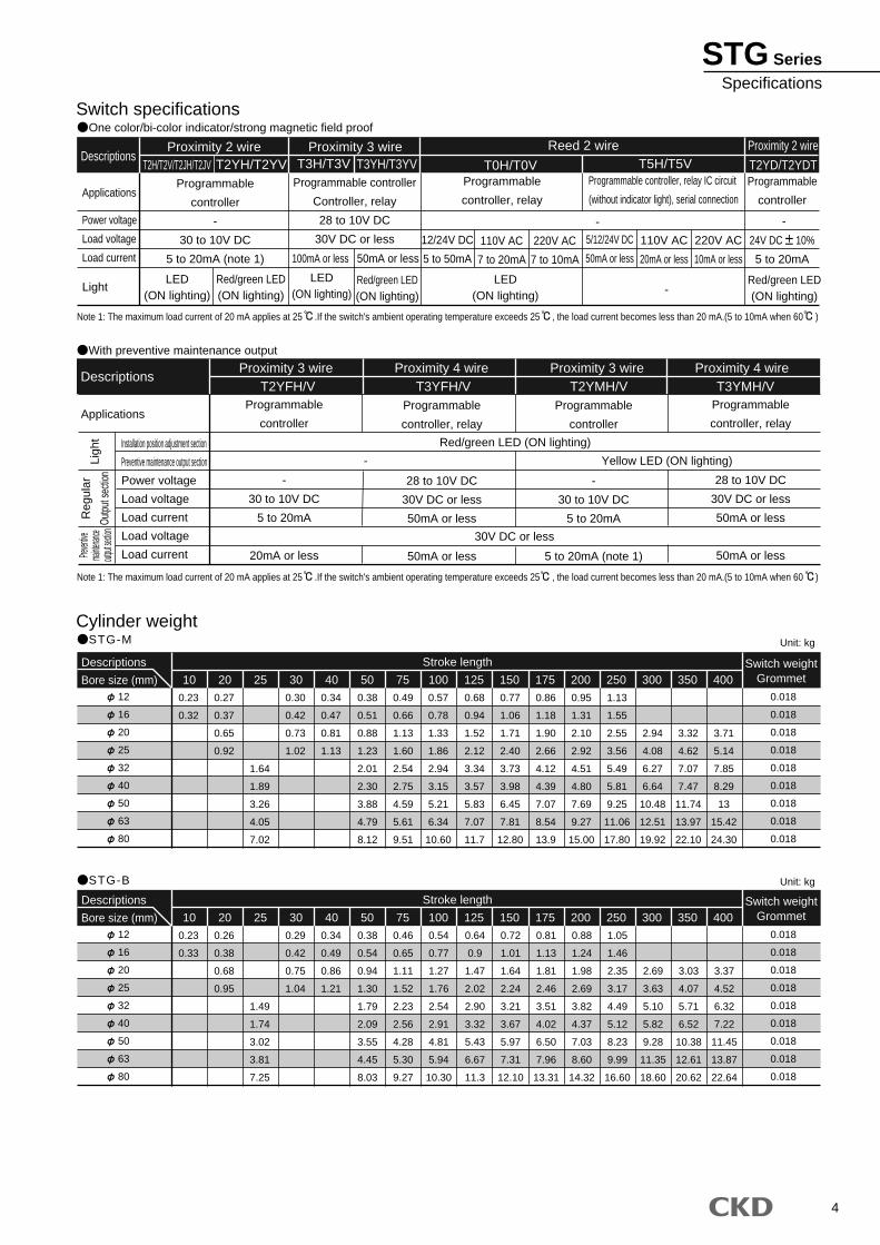
Switch specificationsOne color/bi-color indicator/strong magnetic field proof
Cylinder weightSTG-M
STG-B
Descriptions
Applications
Power voltage
Load voltage
Load current
Light
Reed 2 wire Proximity 2 wire
Programmable
controller
-
30 to 10V DC
5 to 20mA (note 1)
12/24V DC
5 to 50mA
110V AC
7 to 20mA
220V AC
7 to 10mA
5/12/24V DC
50mA or less
110V AC
20mA or less
220V AC
10mA or less
Programmable controller
Controller, relay
28 to 10V DC
30V DC or less
Programmable
controller, relay
Programmable
controller
Programmable controller, relay IC circuit
(without indicator light), serial connection
Proximity 2 wire Proximity 3 wireT2H/T2V/T2JH/T2JV T2YH/T2YV T3H/T3V T3YH/T3YV T0H/T0V T5H/T5V T2YD/T2YDT
- -
-LED
(ON lighting)
LED(ON lighting)
LED(ON lighting)
Red/green LED(ON lighting)
Red/green LED(ON lighting)
Red/green LED(ON lighting)
100mA or less 50mA or less
With preventive maintenance output
Descriptions
ApplicationsProgrammable
controller
-
30 to 10V DC
5 to 20mA
20mA or less
Programmable
controller
-
30 to 10V DC
5 to 20mA
5 to 20mA (note 1)
Programmable
controller, relay
28 to 10V DC
30V DC or less
50mA or less
50mA or less
Programmable
controller, relay
28 to 10V DC
30V DC or less
50mA or less
50mA or less
T2YFH/V T3YFH/V T2YMH/V T3YMH/V
Red/green LED (ON lighting)
30V DC or less
Yellow LED (ON lighting)-
Note 1: The maximum load current of 20 mA applies at 25 .If the switch's ambient operating temperature exceeds 25 , the load current becomes less than 20 mA.(5 to 10mA when 60 )
Note 1: The maximum load current of 20 mA applies at 25 .If the switch's ambient operating temperature exceeds 25 , the load current becomes less than 20 mA.(5 to 10mA when 60 )
Installation position adjustment section
Preventive maintenance output section
Power voltage
Load voltage
Load current
Load voltage
Load current
Reg
ular
Outp
ut se
ction
Preven
tivema
intenan
ceout
put se
ction
Ligh
t
Proximity 3 wire Proximity 4 wire Proximity 3 wire Proximity 4 wire
12
16
20
25
32
40
50
63
80
Descriptions
Bore size (mm)
0.23
0.32
0.27
0.37
0.65
0.92
1.64
1.89
3.26
4.05
7.02
0.30
0.42
0.73
1.02
0.34
0.47
0.81
1.13
0.38
0.51
0.88
1.23
2.01
2.30
3.88
4.79
8.12
0.49
0.66
1.13
1.60
2.54
2.75
4.59
5.61
9.51
0.57
0.78
1.33
1.86
2.94
3.15
5.21
6.34
10.60
0.68
0.94
1.52
2.12
3.34
3.57
5.83
7.07
11.7
0.77
1.06
1.71
2.40
3.73
3.98
6.45
7.81
12.80
0.86
1.18
1.90
2.66
4.12
4.39
7.07
8.54
13.9
0.95
1.31
2.10
2.92
4.51
4.80
7.69
9.27
15.00
1.13
1.55
2.55
3.56
5.49
5.81
9.25
11.06
17.80
2.94
4.08
6.27
6.64
10.48
12.51
19.92
3.32
4.62
7.07
7.47
11.74
13.97
22.10
3.71
5.14
7.85
8.29
13
15.42
24.30
10 20 300 350 400Switch weight
Grommet
0.018
0.018
0.018
0.018
0.018
0.018
0.018
0.018
0.018
75 150125100 17525 30 40 50 200 250
Stroke length
12
16
20
25
32
40
50
63
80
Descriptions
Bore size (mm)
0.23
0.33
0.26
0.38
0.68
0.95
1.49
1.74
3.02
3.81
7.25
0.29
0.42
0.75
1.04
0.34
0.49
0.86
1.21
0.38
0.54
0.94
1.30
1.79
2.09
3.55
4.45
8.03
0.46
0.65
1.11
1.52
2.23
2.56
4.28
5.30
9.27
0.54
0.77
1.27
1.76
2.54
2.91
4.81
5.94
10.30
0.64
0.9
1.47
2.02
2.90
3.32
5.43
6.67
11.3
0.72
1.01
1.64
2.24
3.21
3.67
5.97
7.31
12.10
0.81
1.13
1.81
2.46
3.51
4.02
6.50
7.96
13.31
0.88
1.24
1.98
2.69
3.82
4.37
7.03
8.60
14.32
1.05
1.46
2.35
3.17
4.49
5.12
8.23
9.99
16.60
2.69
3.63
5.10
5.82
9.28
11.35
18.60
3.03
4.07
5.71
6.52
10.38
12.61
20.62
3.37
4.52
6.32
7.22
11.45
13.87
22.64
10 20 300 350 400Switch weight
Grommet
0.018
0.018
0.018
0.018
0.018
0.018
0.018
0.018
0.018
75 150125100 17525 30 40 50 200 250
Stroke length
Unit: kg
Unit: kg
24V DC 10%
5 to 20mA
STG SeriesSpecifications
5
STG Series
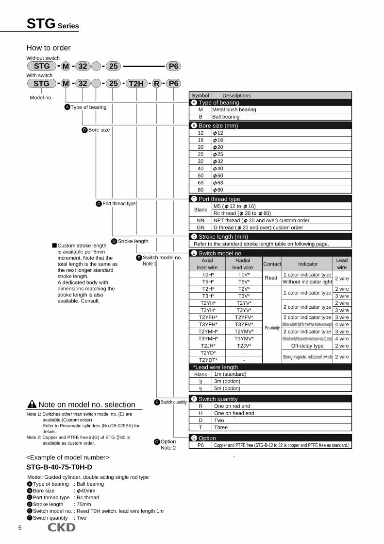
Symbol Descriptions
MB
Metal bush bearingBall bearing
121620253240506380
121620253240506380
Type of bearingA
Bore size (mm)B
2 wire
2 wire3 wire2 wire3 wire3 wire4 wire3 wire4 wire2 wire
2 wire
RHDT
Blank35
One on rod endOne on head endTwoThree
1m (standard)3m (option)5m (option)
Switch quantityF
Blank
NNGN
M5 ( 12 to 16)Rc thread ( 20 to 80)NPT thread ( 20 and over) custom orderG thread ( 20 and over) custom order
Port thread typeC
Refer to the standard stroke length table on following page.Stroke length (mm)D
T0H*T5H*T2H*T3H*
T2YH*T3YH*
T2YFH*T3YFH*T2YMH*T3YMH*T2JH*T2YD*
T2YDT*
T0V*T5V*T2V*T3V*
T2YV*T3YV*
T2YFV*T3YFV*T2YMV*T3YMV*T2JV*
--
Axiallead wire
Radiallead wire
Contact IndicatorLeadwire
Reed
Proximity
1 color indicator typeWithout indicator light
1 color indicator type
2 color indicator type
2 color indicator type(Without indicator light for preventive maintenance output)2 color indicator type
(With indicator light for preventive maintenance output (1 color))Off-delay type
Strong magnetic field proof switch
Switch model no.
*Lead wire length
E
P6 Copper and PTFE free (STG-B-12 to 32 is copper and PTFE free as standard.)OptionG
A
How to orderWithout switch
With switch
B Bore size
C Port thread type
D Stroke length
E Switch model no.Note 1
Model no.
STG M R32 25 T2H
STG M 32 25
P6
P6
Type of bearing
<Example of model number>
STG-B-40-75-T0H-DModel: Guided cylinder, double acting single rod type
Type of bearing : Ball bearingBore size : 40mmPort thread type : Rc threadStroke length : 75mmSwitch model no. : Reed T0H switch, lead wire length 1mSwitch quantity : Two
Note on model no. selection
A
B
C
D
E
F
Note 1: Switches other than switch model no. (E) are available.(Custom order)Refer to Pneumatic cylinders (No.CB-029SA) for details.
Note 2: Copper and PTFE free in(G) of STG- -80 is available as custom order.
is available per 5mm increment. Note that the total length is the same as the next longer standard stroke length.A dedicated body with dimensions matching the stroke length is also available. Consult.
F Switch quantity
G OptionNote 2
MB
Custom stroke length

6
10
20
25
30
40
50
75
100
125
150
175
200
250
300
350
400
SymbolApplicable bore sizeStroke length
(mm)
10
20
25
30
40
50
75
100
125
150
175
200
250
300
350
400
12 16 20 25 32 40 50 63 80
[Standard stroke length table]
Switch model no.( on previous page)
How to order switch
SW T0V
Sta
ndar
d st
roke
leng
thD
Note: Consult with CKD when using the ecological T type switch.
E
STG SeriesHow to order
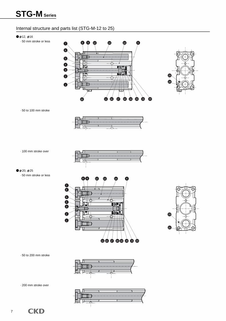
7
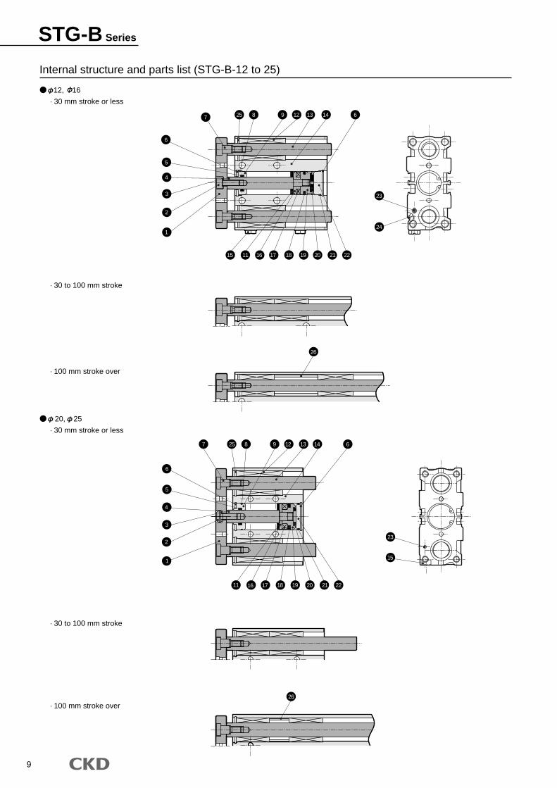
12, 16
· 50 mm stroke or less
· 50 to 100 mm stroke
· 100 mm stroke over
20, 25
· 50 mm stroke or less
· 50 to 200 mm stroke
· 200 mm stroke over
Internal structure and parts list (STG-M-12 to 25)
7
6
5
4
3
2
1
15 11 16 17 18 19 20 21 22
8 9 12 13 14 6
7
6
5
4
3
2
1
15
11 16 17 18 19 20 21 22
8 9 12 13 14 6
23
24
23
STG-M Series
8
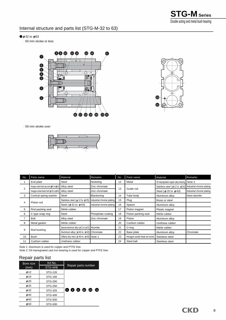
32 to 63
· 50 mm stroke or less
· 50 mm stroke over
Internal structure and parts list (STG-M-32 to 63)
Parts name
End plate
Hexagon socket head cap screw ( 12 to 16)
Hexagon socket button bolt ( 20 to 63)
Conical spring washer
Piston rod
Rod packing seal
C type snap ring
Bolt
Metal gasket
Rod bushing
Bush
Cushion rubber
Material
Steel
Alloy steel
Alloy steel
Steel
Stainless steel ( 12 to 25)
Steel ( 32 to 63)
Nitrile rubber
Steel
Alloy steel
Nitrile rubber
Special aluminum alloy ( 12 to 32)
Aluminum alloy ( 40 to 63)
Oilless dry met ( 40 to 63)
Urethane rubber
Remarks
Nickeling
Zinc chromate
Zinc chromate
Blackening
Industrial chrome plating
Industrial chrome plating
Phosphate coating
Zinc chromate
Alumite
Chromate
Material
Oil impregnated copper alloy bearing
Stainless steel ( 12 to 16)
Steel ( 20 to 63)
Aluminum alloy
Brass or steel
Aluminum alloy
Plastic magnet
Nitrile rubber
Aluminum alloy
Urethane rubber
Nitrile rubber
Aluminum alloy
Stainless steel
Stainless steel
Remarks
Industrial chrome plating
Industrial chrome plating
Hard alumite
Chromate
Parts name
Metal
Guide rod
Tube body
Plug
Spacer
Piston magnet
Piston packing seal
Piston
Cushion rubber
O ring
Base plate
Hexagon socket head set screw
Steel ball
No.
1
2
3
4
5
6
7
8
9
10
11
No.
12
13
14
15
16
17
18
19
20
21
22
23
24
Note 1: Aluminum is used for copper and PTFE free.Note 2: Oil impregnated cast iron bearing is used for copper and PTFE free.
Note 1
Note 2
Bore size(mm)
Kit No.Repair parts number
Repair parts list
STG-M/B
12
16
20
25
32
40
50
63
STG-12K
STG-16K
STG-20K
STG-25K
STG-32K
STG-40K
STG-50K
STG-63K
5 8 11 18 20 21
9 8 10 11 12 13 14 67
6
5
4
3
2
1
15
16 17 18 19 20 21 22
23
STG-M SeriesDouble acting and metal bush bearing
9
12, 16
· 30 mm stroke or less
· 30 to 100 mm stroke
· 100 mm stroke over
20, 25
· 30 mm stroke or less
· 30 to 100 mm stroke
· 100 mm stroke over
Internal structure and parts list (STG-B-12 to 25)
26
2
115
11 16 17 18 19 20 21 22
23
26
3
4
7
6
25 8
5
9 12 13 14 6
2
1
15 11 16 17 18 19 20 21 22
4
3
7
6
25 8
5
9 12 13 14
23
24
6
STG-B Series
10
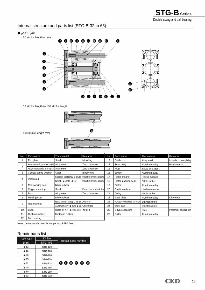
STG-B SeriesDouble acting and ball bearing
32 to 63
· 50 stroke length or less
· 50 stroke length to 100 stroke length
· 100 stroke length over
Internal structure and parts list (STG-B-32 to 63)
Parts name
End plate
Hexagon socket head cap screw ( 12 to 16)
Hexagon socket button bolt ( 20 to 63)
Conical spring washer
Piston rod
Rod packing seal
C type snap ring
Bolt
Metal gasket
Rod bushing
Bush
Cushion rubber
Ball bushing
The material
Steel
Alloy steel
Alloy steel
Steel
Stainless steel ( 12 to 25)
Steel ( 32 to 63)
Nitrile rubber
Steel
Alloy steel
Nitrile rubber
Special aluminum alloy ( 12 to 32)
Aluminum alloy ( 40 to 63)
Oilless dry met ( 40 to 63)
Urethane rubber
Remarks
Nickeling
Zinc chromate
Zinc chromate
Blackening
Industrial chrome plating
Industrial chrome plating
Phosphoric acid salt film
Zinc chromate
Alumite
Chromate
The material
Alloy steel
Aluminum alloy
Brass or is steel.
Aluminum alloy
Plastic magnet
Nitrile rubber
Aluminum alloy
Urethane rubber
Nitrile rubber
Aluminum alloy
Stainless steel
Stainless steel
Steel
Aluminum alloy
Remarks
Industrial chrome plating
Hard alumite
Chromate
Phosphoric acid salt film
Parts name
Guide rod
Tube body
Plug
Spacer
Piston magnet
Piston packing seal
Piston
Cushion rubber
O ring
Base plate
Hexagon socket head set screw
Steel ball
C type snap ring
Collar
No.
1
2
3
4
5
6
7
8
9
10
11
12
No.
13
14
15
16
17
18
19
20
21
22
23
24
25
26
Bore size(mm)
Kit No.Repair parts number
Repair parts list
STG-M/B
12
16
20
25
32
40
50
63
STG-12K
STG-16K
STG-20K
STG-25K
STG-32K
STG-40K
STG-50K
STG-63K
5 8 11 18 20 21
26
5
6
7 9 25 8 10 11 12 13 14 6
2
1
3
4
15
16 17 18 19 20 21 22
23
Note 1: Aluminum is used for copper and PTFE free.
Note 1
11
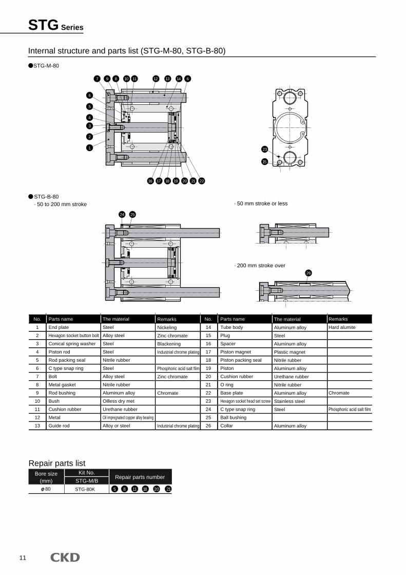
STG-M-80
STG-B-80 · 50 to 200 mm stroke · 50 mm stroke or less
· 200 mm stroke over
Internal structure and parts list (STG-M-80, STG-B-80)
Parts name
End plate
Hexagon socket button bolt
Conical spring washer
Piston rod
Rod packing seal
C type snap ring
Bolt
Metal gasket
Rod bushing
Bush
Cushion rubber
Metal
Guide rod
The material
Steel
Alloy steel
Steel
Steel
Nitrile rubber
Steel
Alloy steel
Nitrile rubber
Aluminum alloy
Oilless dry met
Urethane rubber
Oil impregnated copper alloy bearing
Alloy or steel
Remarks
Nickeling
Zinc chromate
Blackening
Industrial chrome plating
Phosphoric acid salt film
Zinc chromate
Chromate
Industrial chrome plating
The material
Aluminum alloy
Steel
Aluminum alloy
Plastic magnet
Nitrile rubber
Aluminum alloy
Urethane rubber
Nitrile rubber
Aluminum alloy
Stainless steel
Steel
Aluminum alloy
Remarks
Hard alumite
Chromate
Phosphoric acid salt film
Parts name
Tube body
Plug
Spacer
Piston magnet
Piston packing seal
Piston
Cushion rubber
O ring
Base plate
Hexagon socket head set screw
C type snap ring
Ball bushing
Collar
No.
1
2
3
4
5
6
7
8
9
10
11
12
13
No.
14
15
16
17
18
19
20
21
22
23
24
25
26
Bore size(mm)
Kit No.Repair parts number
Repair parts list
STG-M/B80 STG-80K 5 8 11 18 20 21
6
7 9 8 10 11 12
15
16 17 18 19 20 21 22
23
24 25
13 14 6
5
4
3
2
1
26
STG Series
12
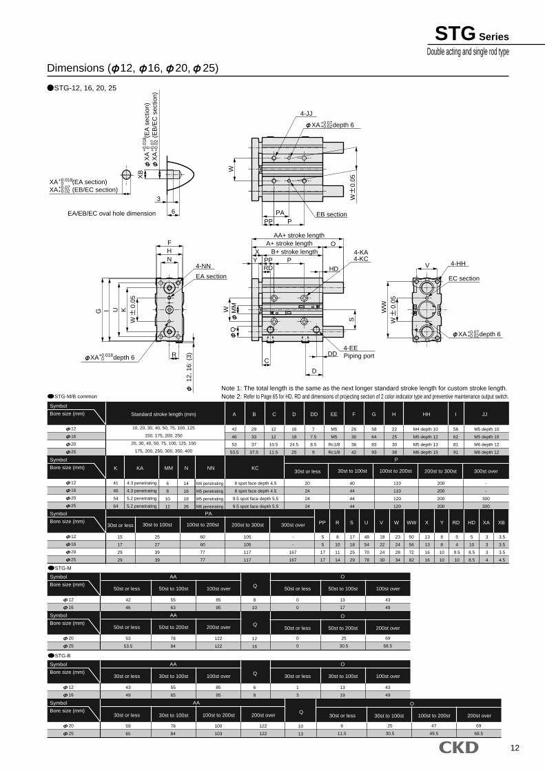
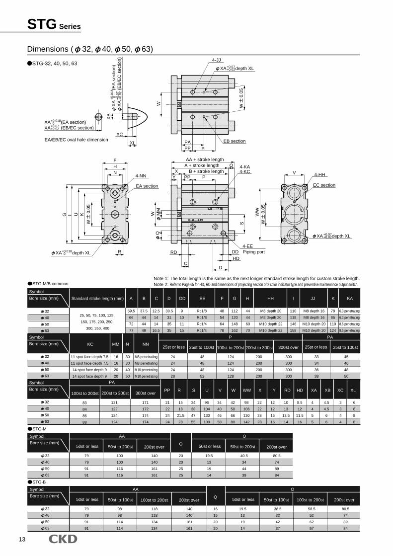
Note 1: The total length is the same as the next longer standard stroke length for custom stroke length.Note 2: Refer to Page 65 for HD, RD and dimensions of projecting section of 2 color indicator type and preventive maintenance output switch.STG-M/B common
STG-M
12
16
20
25
Symbol
Bore size (mm)
STG-12, 16, 20, 25
EA/EB/EC oval hole dimension
Dimensions ( 12, 16, 20, 25)
42
46
53
53.5
29
33
37
37.5
12
12
10.5
11.5
16
18
24.5
25
7
7.5
8.5
9
M5
M5
Rc1/8
Rc1/8
26
30
36
42
58
64
83
93
22
25
30
38
56
62
81
91
3.5
3.5
3.5
4.5
3
3
3
4
5
10
8.5
8.5
5
4
9.5
10
8
8
10
10
13
13
16
16
50
56
72
82
23
24
28
34
18
22
24
30
48
54
70
78
17
18
25
29
8
10
11
14
5
5
17
17
-
-
167
167
105
105
117
117
60
60
77
77
25
27
39
39
42
46
55
63
85
95
8
10
12
16
15
17
29
29
41
46
54
64
M4 depth 10
M5 depth 12
M5 depth 13
M6 depth 15
M5 depth 10
M5 depth 10
M6 depth 12
M6 depth 12
4.3 penetrating
4.3 penetrating
5.2 penetrating
5.2 penetrating
10, 20, 30, 40, 50, 75, 100, 125
150, 175, 200, 250
20, 30, 40, 50, 75, 100, 125, 150
175, 200, 250, 300, 350, 400
12
16
20
25
Symbol
Bore size (mm)
12
16
20
25
Symbol
Bore size (mm)
12
16
Symbol
Bore size (mm)
0
0
13
17
43
49
0
0
25
30.5
69
68.5
53
53.5
78
84
122
122
20
25
Symbol
Bore size (mm)
STG-B
43
49
55
65
85
95
6
8
10
13
12
16
Symbol
Bore size (mm)
1
3
13
19
43
49
6
11.5
25
30.5
47
49.5
69
68.5
59
65
78
84
100
103
122
122
20
25
Symbol
Bore size (mm)
Standard stroke length (mm) A
MM N NN
PP R S U V W WW X Y RD HD XA XB
KC30st or less
30st or less
200st to 300st 300st over30st to 100st 100st to 200st
200st to 300st 300st over30st to 100st 100st to 200st
B C D DD EE F G H HH
P
PA
Q100st over50st or less 50st to 100st
AA
100st over50st or less 50st to 100st
O
200st over50st or less 50st to 200st
O
Q200st over50st or less 50st to 200st
AA
Q100st over30st or less 30st to 100st
AA
100st over30st or less 30st to 100st
O
100st to 200st 200st over30st or less 30st to 100st
O
Q100st to 200st 200st over30st or less 30st to 100st
AA
I JJ
K KA
6
8
10
12
14
16
18
26
M4 penetrating
M5 penetrating
M5 penetrating
M6 penetrating
8 spot face depth 4.5
8 spot face depth 4.5
9.5 spot face depth 5.5
9.5 spot face depth 5.5
20
24
24
24
40
44
44
44
110
110
120
120
200
200
200
200
-
-
300
300
WW
6
PPA
PPW
12, 1
6: (
3)R
N
FH
I U K
QW M
M
PP PB+ stroke length
A+ stroke lengthAA+ stroke length
YX
O
S
HD
DD
D
C
RD
3
XB
XA (EA section)XA (EB/EC section)
+0.018 0+0.07+0.02
XA
(E
A s
ectio
n)X
A
(
EB
/EC
sec
tion)
+0.
018
0 +0.
07+
0.02
G
4-NN
EA section
XA depth 6+0.018 0
4-EEPiping port
4-KA4-KC
V
XA depth 6+0.07+0.02
4-HH
EC section
XA depth 6+0.07+0.02
EB section
4-JJ
W
0.0
5
W
0.0
5
W
0.0
5
STG SeriesDouble acting and single rod type
13
Note 1: The total length is the same as the next longer standard stroke length for custom stroke length.Note 2: Refer to Page 65 for HD, RD and dimensions of projecting section of 2 color indicator type and preventive maintenance output switch.STG-M/B common
STG-M
32
40
50
63
Symbol
Bore size (mm) Standard stroke length (mm) A
KC MM
PP R S U V W WW X Y RD HD XA XB XC XL
N NN
P PA
PA
B C D DD EE F G H HH I JJ K KA
STG-32, 40, 50, 63
Dimensions ( 32, 40, 50, 63)
79
79
91
91
100
100
116
116
140
140
161
161
20
20
25
25
32
40
50
63
Symbol
Bore size (mm)
32
40
50
63
Symbol
Bore size (mm)
32
40
50
63
Symbol
Bore size (mm)
19.5
13
19
14
40.5
34
44
39
80.5
74
89
84
STG-B
79
79
91
91
98
98
114
114
118
118
134
134
16
16
20
20
140
140
161
161
32
40
50
63
Symbol
Bore size (mm)
19.5
13
19
14
38.5
32
42
37
58.5
52
62
57
80.5
74
89
84
25st or less
200st to 300st 300st over
25st to 100st 100st to 200st 200st to 300st 25st or less 25st to 100st
100st to 200st
300st over
EA/EB/EC oval hole dimension
Q200st over50st or less 50st to 200st
AA
200st over50st or less 50st to 200st
O
Q100st to 200st 200st over50st or less 50st to 100st
AA
50st or less 50st to 100st 100st to 200st 200st over
O
59.5
66
72
77
11 spot face depth 7.5
11 spot face depth 7.5
14 spot face depth 9
14 spot face depth 9
16
16
20
20
30
30
40
50
M8 penetrating
M8 penetrating
M10 penetrating
M10 penetrating
24
24
24
28
121
122
124
124
171
172
174
174
21
22
24
24
15
18
21.5
28
34
38
47
55
96
104
130
130
34
40
46
58
42
50
66
80
98
106
130
142
22
22
28
28
12
12
16
16
10
13
13.5
14
8.5
12
11.5
16
4
4
5
5
4.5
4.5
6
6
3
3
4
4
6
6
8
8
48
48
48
52
124
124
124
128
300
300
300
300
200
200
200
200
33
34
36
38
45
46
48
50
83
84
86
88
37.5
44
44
49
12.5
14
14
16.5
30.5
31
35
35
9
10
11
15
Rc1/8
Rc1/8
Rc1/4
Rc1/4
48
54
64
78
112
120
148
162
44
44
60
70
110
118
146
158
M8 depth 20
M8 depth 20
M10 depth 22
M10 depth 22
M8 depth 16
M8 depth 16
M10 depth 20
M10 depth 20
78
86
110
124
6.3 penetrating
6.3 penetrating
8.6 penetrating
8.6 penetrating
25, 50, 75, 100, 125,
150, 175, 200, 250,
300, 350, 400
W
PAPP P
UI
R
G
NHF
C
PP PYX B + stroke length
A + stroke length OAA + stroke length
MM
WQ
S
RDHD
V
WW
K
XC
XL
XB
XA (EA section)XA (EB/EC section)
+0.018 0+0.07+0.02
XA
(E
A s
ectio
n)X
A
(
EB
/EC
sec
tion)
+0.
018
0 +0.
07+
0.02
XA depth XL+0.07+0.02
4-JJ
EB section
4-NN
EA section
XA depth XL+0.018 0
4-EEPiping port
4-KA4-KC
XA depth XL+0.07+0.02
4-HH
EC section
DD
D
W
0.0
5
W
0.0
5
W
0.0
5
STG Series
14
A B
P
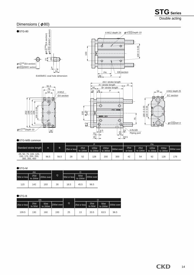
STG-80
Dimensions ( 80)
Standard stroke length25st or less 25st
to 100st100st
to 200st200st
to 300st300st over
PA
25stor less
25stto 100st
100stto 200st
200stto 300st
300st over
AA
25st or less 25stto 50st
50stto 200st
200st over
O
25st or less 25stto 50st
50stto 200st
200st over
AA
50st or less 25stto 200st
200st over
O
50st or less 50stto 200st
200st overQ
Q
25, 50, 75, 100, 125,150, 175, 200, 250,
300, 350, 40096.5 56.5 28 52 128 200 300 42 54 92 128 178
115 142 193 30 18.5 45.5 96.5
STG-M/B common
109.5 130 160 193 25 13 33.5 63.5 96.5
STG-B
STG-M
5
6
(
EB
/EC
sec
tion)
6
(
EA
sec
tion)
100
4-M12 depth 24
28
PA
P
EB section
54 4-M12 depth 25
EC section
22 28 P40 B+ stroke length
A+ stroke lengthAA+ stroke length
28
4-M12
EA section
6 (EB/EC section)
6 (EA section)
EA/EB/EC oval hole dimension
(7)
10
O10
0 25Q
19
18
4.5
424215
19.5
4-Rc3/8Piping port
75
7552
91.5
156
174
198
202
6 Depth 10
6 Depth 10
6 Depth 10
100
0
.05
100
0
.05
100
0
.05
180
0
.05
+0.018+0
+0.
018
+0
+0.
07+
0.02
+0.07+0.02
+0.07+0.02
+0.07+0.02
+0.018 0
STG SeriesDouble acting
15
JIS symbol
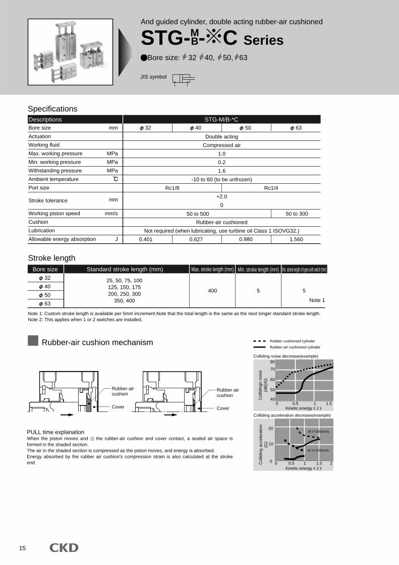
And guided cylinder, double acting rubber-air cushioned
STG-MB- C Series
Bore size: 32 40, 50, 63
Rubber-aircushion
Cover
Rubber-aircushion
Cover
Rubber cushioned cylinder
Rubber-air cushioned cylinder
Col
lidin
g ac
cele
ratio
n(G
)
Kinetic energy(J)
20
10
0 0.5 1 1.5 2 0
At V=300mm/s
At V=100mm/s
Colliding noise decrease(example)
Col
lidin
gn n
oise
(dB
(A))
Kinetic energy(J)
80
70
60
50
400 0.5 1 1.5
Colliding acceleration decrease(example)
Stroke length
32
40
50
63
25, 50, 75, 100125, 150, 175200, 250, 300
350, 400
400 5
Bore size Standard stroke length (mm) Max. stroke length (mm) Min. stroke length (mm) Min. stroke length of types with switch (mm)
5
Note 1
Note 1: Custom stroke length is available per 5mm increment.Note that the total length is the same as the next longer standard stroke length.Note 2: This applies when 1 or 2 switches are installed.
STG-M/B-*CBore size
Actuation
Working fluid
Max. working pressure
Min. working pressure
Withstanding pressure
Ambient temperature
Port size
Stroke tolerance
Working piston speed
Cushion
Lubrication
Allowable energy absorption
mm
MPa
MPa
MPa
mm
mm/s
J
Double acting
Compressed air
1.0
0.2
1.6
-10 to 60 (to be unfrozen)
+2.0
0
Rubber-air cushioned
Not required (when lubricating, use turbine oil Class 1 ISOVG32.)
50
0.980
50 to 500 50 to 300
Rc1/8 Rc1/4
32 40 63
0.401 0.627 1.560
SpecificationsDescriptions
Rubber-air cushion mechanism
PULL time explanationWhen the piston moves and the rubber-air cushion and cover contact, a sealed air space is formed in the shaded section.The air in the shaded section is compressed as the piston moves, and energy is absorbed.Energy absorbed by the rubber air cushion's compression strain is also calculated at the stroke end.
16
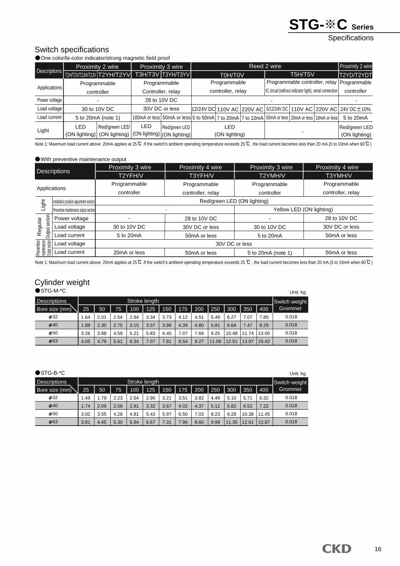
Switch specificationsOne color/bi-color indicator/strong magnetic field proof
Cylinder weightSTG-M-*C
STG-B-*C
Descriptions
Applications
Power voltage
Load voltage
Load current
Light
Reed 2 wire Proximity 2 wire
Programmable
controller
-
30 to 10V DC
5 to 20mA (note 1)
12/24V DC
5 to 50mA
110V AC
7 to 20mA
220V AC
7 to 10mA
5/12/24V DC
50mA or less
110V AC
20mA or less
220V AC
10mA or less
Programmable
Controller, relay
28 to 10V DC
30V DC or less
Programmable
controller, relay
Programmable
controller
Programmable controller, relay
IC circuit (without indicator light), serial connection
Proximity 2 wire Proximity 3 wireT2H/T2V/T2JH/T2JV T2YH/T2YV T3H/T3V T3YH/T3YV T0H/T0V T5H/T5V T2YD/T2YDT
- -
-LED
(ON lighting)
LED(ON lighting)
LED(ON lighting)
Red/green LED(ON lighting)
Red/green LED(ON lighting)
Red/green LED(ON lighting)
100mA or less 50mA or less
With preventive maintenance output
Descriptions
ApplicationsProgrammable
controller
-
30 to 10V DC
5 to 20mA
20mA or less
Programmable
controller
-
30 to 10V DC
5 to 20mA
5 to 20mA (note 1)
Programmable
controller, relay
28 to 10V DC
30V DC or less
50mA or less
50mA or less
Programmable
controller, relay
28 to 10V DC
30V DC or less
50mA or less
50mA or less
T2YFH/V T3YFH/V T2YMH/V T3YMH/V
Red/green LED (ON lighting)
30V DC or less
Yellow LED (ON lighting)-
Note 1: Maximum load current above: 20mA applies at 25 .If the switch's ambient operating temperature exceeds 25 , the load current becomes less than 20 mA.(5 to 10mA when 60 )
Note 1: Maximum load current above: 20mA applies at 25 .If the switch's ambient operating temperature exceeds 25 , the load current becomes less than 20 mA.(5 to 10mA when 60 )
Installation position adjustment section
Preventive maintenance output section
Power voltage
Load voltage
Load current
Load voltage
Load current
Reg
ular
Outp
ut se
ction
Prev
entiv
ema
intenan
ceOu
tput se
ction
Ligh
t
Proximity 3 wire Proximity 4 wire Proximity 3 wire Proximity 4 wire
32
40
50
63
Descriptions
Bore size (mm)
1.64
1.89
3.26
4.05
2.01
2.30
3.88
4.79
2.54
2.75
4.59
5.61
2.94
3.15
5.21
6.34
3.34
3.57
5.83
7.07
3.73
3.98
6.45
7.81
4.12
4.39
7.07
8.54
4.51
4.80
7.69
9.27
5.49
5.81
9.25
11.06
6.27
6.64
10.48
12.51
7.07
7.47
11.74
13.97
7.85
8.29
13.00
15.42
300 350 400Switch weight
Grommet
0.018
0.018
0.018
0.018
75 150125100 17525 50 200 250
Stroke length
32
40
50
63
Descriptions
Bore size (mm)
1.49
1.74
3.02
3.81
1.79
2.09
3.55
4.45
2.23
2.56
4.28
5.30
2.54
2.91
4.81
5.94
2.90
3.32
5.43
6.67
3.21
3.67
5.97
7.31
3.51
4.02
6.50
7.96
3.82
4.37
7.03
8.60
4.49
5.12
8.23
9.99
5.10
5.82
9.28
11.35
5.71
6.52
10.38
12.61
6.32
7.22
11.45
13.87
300 350 400Switch weight
Grommet
0.018
0.018
0.018
0.018
75 150125100 17525 50 200 250
Stroke length
Unit: kg
Unit: kg
24V DC 10%
5 to 20mA
STG- C SeriesSpecifications
17
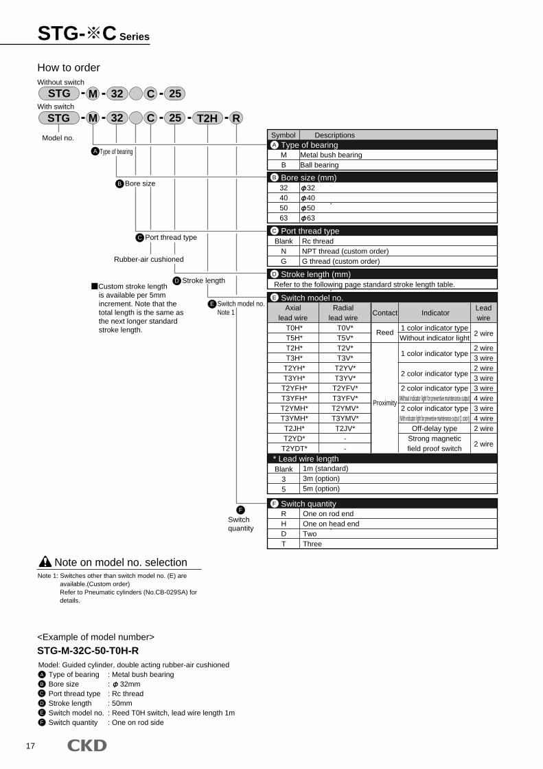
STG- C Series
Symbol Descriptions
MB
Metal bush bearingBall bearing
32405063
32405063
Type of bearingA
Bore size (mm)B
2 wire
2 wire3 wire2 wire3 wire3 wire4 wire3 wire4 wire2 wire
2 wire
RHDT
Blank35
One on rod endOne on head endTwoThree
1m (standard)3m (option)5m (option)
Switch quantityF
BlankNG
Rc threadNPT thread (custom order)G thread (custom order)
Port thread typeC
Refer to the following page standard stroke length table.Stroke length (mm)D
T0H*T5H*T2H*T3H*
T2YH*T3YH*
T2YFH*T3YFH*T2YMH*T3YMH*T2JH*T2YD*
T2YDT*
T0V*T5V*T2V*T3V*
T2YV*T3YV*
T2YFV*T3YFV*T2YMV*T3YMV*T2JV*
--
Axiallead wire
Radiallead wire
Contact IndicatorLeadwire
Reed
Proximity
1 color indicator typeWithout indicator light
1 color indicator type
2 color indicator type
2 color indicator type(Without indicator light for preventive maintenance output)2 color indicator type
(With indicator light for preventive maintenance output (1 color))Off-delay type
Strong magneticfield proof switch
Switch model no.
* Lead wire length
E
A
How to orderWithout switch
With switch
B Bore size
C
Model no.
STG M 32
STG M C
C
32
R25 T2H
25
<Example of model number>
STG-M-32C-50-T0H-RModel: Guided cylinder, double acting rubber-air cushioned
Type of bearing : Metal bush bearingBore size : 32mmPort thread type : Rc threadStroke length : 50mmSwitch model no. : Reed T0H switch, lead wire length 1mSwitch quantity : One on rod side
Note on model no. selection
A
B
C
D
E
F
Note 1: Switches other than switch model no. (E) are available.(Custom order)Refer to Pneumatic cylinders (No.CB-029SA) for details.
F
Switchquantity
D Stroke length
Rubber-air cushioned
Port thread type
E Switch model no.Note 1
Type of bearing
is available per 5mm increment. Note that the total length is the same as the next longer standard stroke length.
Custom stroke length
18
STG- C SeriesHow to order
25
50
75
100
125
150
175
200
250
300
350
400
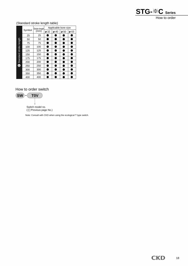
SymbolApplicable bore sizeStroke length
(mm)
25
50
75
100
125
150
175
200
250
300
350
400
32 40 50 63
(Standard stroke length table)
Switch model no.( Previous page No.)
How to order switch
SW T0V
E
Sta
ndar
d st
roke
leng
thC
Note: Consult with CKD when using the ecological T type switch.
19
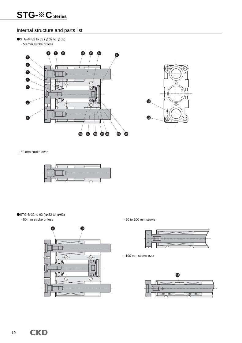
STG-M-32 to 63 ( 32 to 63)
· 50 mm stroke or less
· 50 mm stroke over
STG-B-32 to 63 ( 32 to 63)
· 50 mm stroke or less
Internal structure and parts list
· 50 to 100 mm stroke
· 100 mm stroke over
7
9 8 11 12 13 146
6
5
4
3
2
1 15
24 25
16 17 18 19 20 21 22
23
10
STG- C Series
20
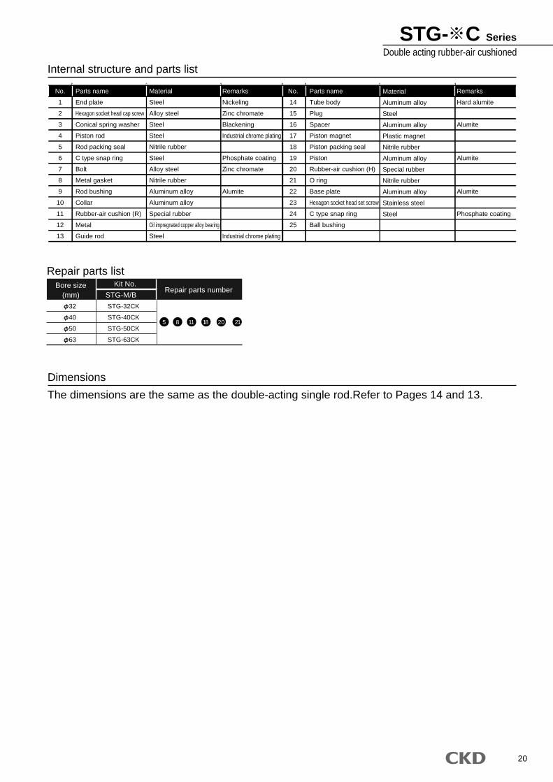
STG- C SeriesDouble acting rubber-air cushioned
Internal structure and parts list
Dimensions
The dimensions are the same as the double-acting single rod.Refer to Pages 14 and 13.
Bore size(mm)
Kit No.Repair parts number
Repair parts list
STG-M/B
32
40
50
63
STG-32CK
STG-40CK
STG-50CK
STG-63CK
5 8 11 18 20 21
Parts name
End plate
Hexagon socket head cap screw
Conical spring washer
Piston rod
Rod packing seal
C type snap ring
Bolt
Metal gasket
Rod bushing
Collar
Rubber-air cushion (R)
Metal
Guide rod
Material
Steel
Alloy steel
Steel
Steel
Nitrile rubber
Steel
Alloy steel
Nitrile rubber
Aluminum alloy
Aluminum alloy
Special rubber
Oil impregnated copper alloy bearing
Steel
Remarks
Nickeling
Zinc chromate
Blackening
Industrial chrome plating
Phosphate coating
Zinc chromate
Alumite
Industrial chrome plating
Material
Aluminum alloy
Steel
Aluminum alloy
Plastic magnet
Nitrile rubber
Aluminum alloy
Special rubber
Nitrile rubber
Aluminum alloy
Stainless steel
Steel
Remarks
Hard alumite
Alumite
Alumite
Alumite
Phosphate coating
Parts name
Tube body
Plug
Spacer
Piston magnet
Piston packing seal
Piston
Rubber-air cushion (H)
O ring
Base plate
Hexagon socket head set screw
C type snap ring
Ball bushing
No.
1
2
3
4
5
6
7
8
9
10
11
12
13
No.
14
15
16
17
18
19
20
21
22
23
24
25
21
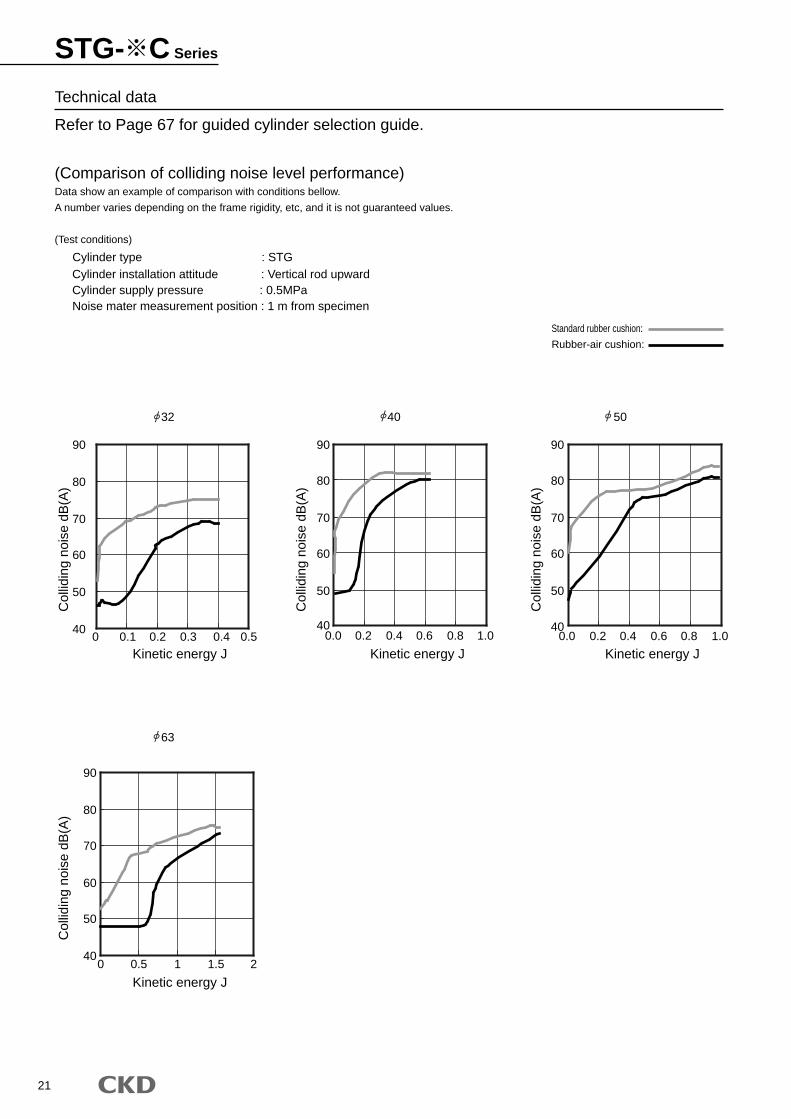
Technical data
Refer to Page 67 for guided cylinder selection guide.
(Comparison of colliding noise level performance)Data show an example of comparison with conditions bellow.
A number varies depending on the frame rigidity, etc, and it is not guaranteed values.
(Test conditions)
Cylinder type : STG Cylinder installation attitude : Vertical rod upward Cylinder supply pressure : 0.5MPa Noise mater measurement position : 1 m from specimen
32 40 50
63
Standard rubber cushion:
Rubber-air cushion:
40
50
60
70
80
90
0 0.1 0.2 0.3 0.4 0.5
Kinetic energy J
Col
lidin
g no
ise
dB(A
)
40
50
60
70
80
90
0.0 0.2 0.4 0.6 0.8 1.0
Kinetic energy J
Col
lidin
g no
ise
dB(A
)
40
50
60
70
80
90
0.0 0.2 0.4 0.6 0.8 1.0
Kinetic energy J
Col
lidin
g no
ise
dB(A
)
40
50
60
70
80
90
0 0.5 1 1.5 2
Kinetic energy J
Col
lidin
g no
ise
dB(A
)STG- C Series
22
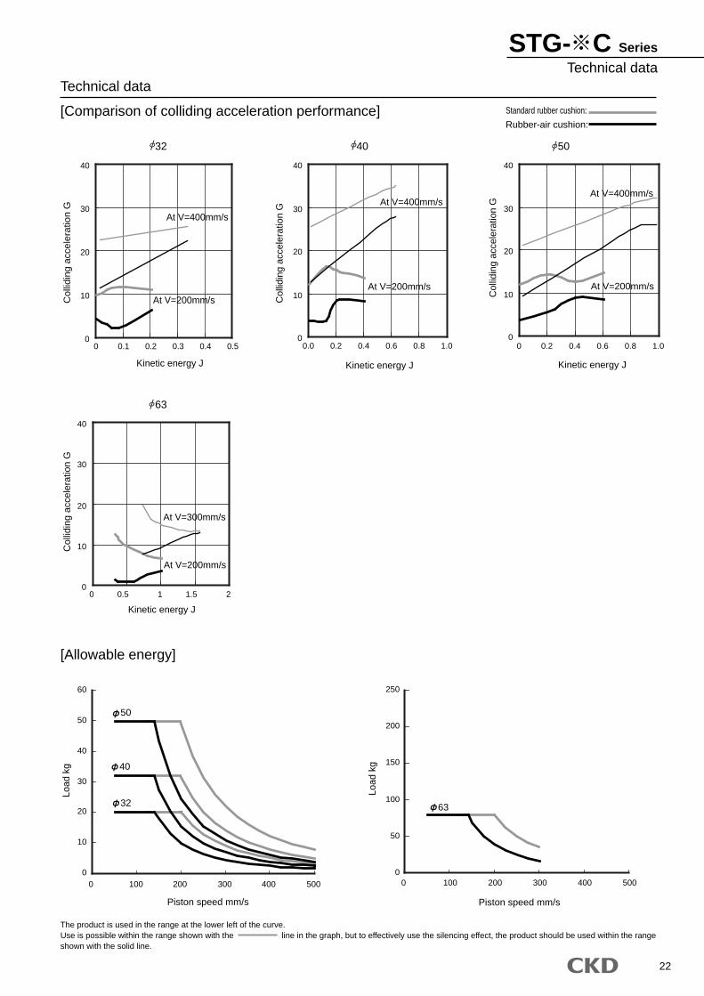
STG- C Series
Technical dataTechnical data
[Comparison of colliding acceleration performance] Standard rubber cushion:
Rubber-air cushion:
32 40 50
[Allowable energy]
The product is used in the range at the lower left of the curve.Use is possible within the range shown with the line in the graph, but to effectively use the silencing effect, the product should be used within the rangeshown with the solid line.
0
10
20
30
40
0 0.1 0.2 0.3 0.4 0.5
Kinetic energy J
Col
lidin
g ac
cele
ratio
n G
At V=400mm/s
At V=200mm/s
0
10
20
30
40
0.0 0.2 0.4 0.6 0.8 1.0
Kinetic energy J
Col
lidin
g ac
cele
ratio
n G At V=400mm/s
At V=200mm/s
0
10
20
30
40
0 0.2 0.4 0.6 0.8 1.0
Kinetic energy J
Col
lidin
g ac
cele
ratio
n G
At V=400mm/s
At V=200mm/s
0
10
20
30
40
0 0.5 1 1.5 2
Kinetic energy J
Col
lidin
g ac
cele
ratio
n G
At V=300mm/s
At V=200mm/s
0
10
20
30
40
50
60
0 100 200 300 400 500
Piston speed mm/s
Load
kg
50
32
40
0
50
100
150
200
250
0 100 200 300 400 500
Piston speed mm/s
Load
kg
63
63
23
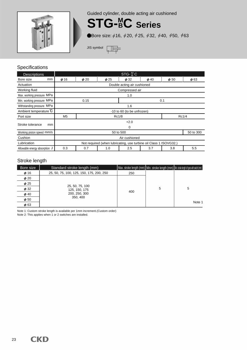
Guided cylinder, double acting air cushioned
STG-MBC Series
Bore size: 16, 20, 25, 32, 40, 50, 63
JIS symbol
Specifications
Bore size
Actuation
Working fluid
Max. working pressure
Min. working pressure
Withstanding pressure
Ambient temperature
Port size
Working piston speed
Cushion
Lubrication
Allowable energy absorption
Double acting air cushioned
Compressed air
1.0
1.6
-10 to 60 (to be unfrozen)
+2.0
0
Air cushioned
Not required (when lubricating, use turbine oil Class 1 ISOVG32.)
M5
0.3 0.7 1.0 2.5 3.7 3.8 5.5
Rc1/8 Rc1/4
50 to 500 50 to 300
0.1
Descriptions 16 20
0.15
25 32 40 50 63
Stroke length
16
20
25
32
40
50
63
25, 50, 75, 100125, 150, 175200, 250, 300
350, 400
25, 50, 75, 100, 125, 150, 175, 200, 250
400
250
5
Bore size Standard stroke length (mm) Max. stroke length (mm) Min. stroke length (mm) Min. stroke length of types with switch (mm)
5
mm
MPa
MPa
MPa
mm/s
J
Stroke tolerance mm
Note 1: Custom stroke length is available per 1mm increment.(Custom order)Note 2: This applies when 1 or 2 switches are installed.
Note 1
STG- CMB
24
STG- C SeriesSpecifications
MB
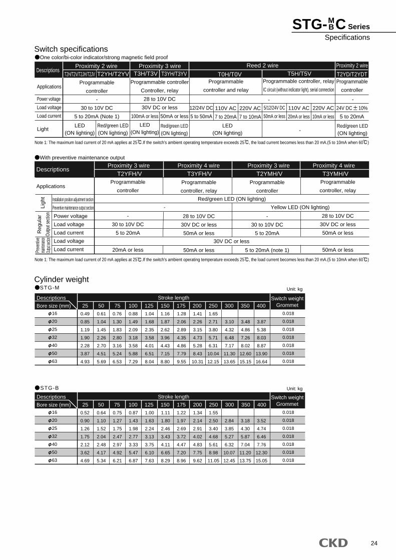
Switch specificationsOne color/bi-color indicator/strong magnetic field proof
Cylinder weightSTG-M
STG-B
Descriptions
Applications
Power voltage
Load voltage
Load current
Light
Reed 2 wire Proximity 2 wire
Programmable
controller
-
30 to 10V DC
5 to 20mA (Note 1)
12/24V DC
5 to 50mA
110V AC
7 to 20mA
220V AC
7 to 10mA
5/12/24V DC
50mA or less
110V AC
20mA or less
220V AC
10mA or less
Programmable controller
Controller, relay
28 to 10V DC
30V DC or less
Programmable
controller and relay
Programmable
controller
Programmable controller, relay
IC circuit (without indicator light), serial connection
Proximity 2 wire Proximity 3 wireT2H/T2V/T2JH/T2JV T2YH/T2YV T3H/T3V T3YH/T3YV T0H/T0V T5H/T5V T2YD/T2YDT
- -
-LED
(ON lighting)
LED(ON lighting)
LED(ON lighting)
Red/green LED(ON lighting)
Red/green LED(ON lighting)
Red/green LED(ON lighting)
100mA or less 50mA or less
With preventive maintenance output
Descriptions
ApplicationsProgrammable
controller
-
30 to 10V DC
5 to 20mA
20mA or less
Programmable
controller
-
30 to 10V DC
5 to 20mA
5 to 20mA (note 1)
Programmable
controller, relay
28 to 10V DC
30V DC or less
50mA or less
50mA or less
Programmable
controller, relay
28 to 10V DC
30V DC or less
50mA or less
50mA or less
T2YFH/V T3YFH/V T2YMH/V T3YMH/V
Red/green LED (ON lighting)
30V DC or less
Yellow LED (ON lighting)-
Note 1: The maximum load current of 20 mA applies at 25 .If the switch's ambient operating temperature exceeds 25 , the load current becomes less than 20 mA.(5 to 10mA when 60 )
Note 1: The maximum load current of 20 mA applies at 25 .If the switch's ambient operating temperature exceeds 25 , the load current becomes less than 20 mA.(5 to 10mA when 60 )
Installation position adjustment section
Preventive maintenance output section
Power voltage
Load voltage
Load current
Load voltage
Load current
Reg
ular
Outp
ut se
ction
Prev
entiv
ema
intenan
ceOu
tput se
ction
Ligh
t
Proximity 3 wire Proximity 4 wire Proximity 3 wire Proximity 4 wire
16
20
25
32
40
50
63
Descriptions
Bore size (mm)
0.49
0.85
1.19
1.90
2.28
3.87
4.93
0.61
1.04
1.45
2.26
2.70
4.51
5.69
0.76
1.30
1.83
2.80
3.16
5.24
6.53
0.88
1.49
2.09
3.18
3.58
5.88
7.29
1.04
1.68
2.35
3.58
4.01
6.51
8.04
1.16
1.87
2.62
3.96
4.43
7.15
8.80
1.28
2.06
2.89
4.35
4.86
7.79
9.55
1.41
2.26
3.15
4.73
5.28
8.43
10.31
1.65
2.71
3.80
5.71
6.31
10.04
12.15
3.10
4.32
6.48
7.17
11.30
13.65
3.48
4.86
7.26
8.02
12.60
15.15
3.87
5.38
8.03
8.87
13.90
16.64
25 50 300 350 400Switch weight
Grommet
0.018
0.018
0.018
0.018
0.018
0.018
0.018
75 150125100 175 200 250
Stroke length
16
20
25
32
40
50
63
Descriptions
Bore size (mm)
0.52
0.90
1.26
1.75
2.12
3.62
4.69
0.64
1.10
1.52
2.04
2.48
4.17
5.34
0.75
1.27
1.75
2.47
2.97
4.92
6.21
0.87
1.43
1.98
2.77
3.33
5.47
6.87
1.00
1.63
2.24
3.13
3.75
6.10
7.63
1.11
1.80
2.46
3.43
4.11
6.65
8.29
1.22
1.97
2.69
3.72
4.47
7.20
8.96
1.34
2.14
2.91
4.02
4.83
7.75
9.62
1.55
2.50
3.40
4.68
5.61
8.98
11.05
2.84
3.85
5.27
6.32
10.07
12.45
3.18
4.30
5.87
7.04
11.20
13.75
3.52
4.74
6.46
7.76
12.30
15.05
300 350 400Switch weight
Grommet
0.018
0.018
0.018
0.018
0.018
0.018
0.018
75 150125100 17525 50 200 250
Stroke length
Unit: kg
Unit: kg
24V DC 10%
5 to 20mA
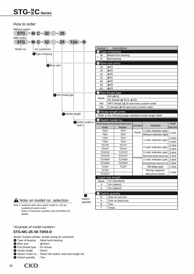
25
Symbol Descriptions
MB
Metal bush bearingBall bearing
16202532405063
16202532405063
Type of bearingA
Bore size (mm)B
2 wire
2 wire3 wire2 wire3 wire3 wire4 wire3 wire4 wire2 wire
2 wire
RHDT
Blank35
One on rod endOne on head endTwoThree
1m (standard)3m (option)5m (option)
Switch quantityF
Blank
NNGN
M5 ( 16)Rc thread ( 20 to 63)NPT thread ( 20 and over) custom orderG thread ( 20 and over) custom order
Port thread typeC
Refer to the following page standard stroke length table.Stroke length (mm)D
T0H*T5H*T2H*T3H*
T2YH*T3YH*
T2YFH*T3YFH*T2YMH*T3YMH*T2JH*T2YD*
T2YDT*
T0V*T5V*T2V*T3V*
T2YV*T3YV*
T2YFV*T3YFV*T2YMV*T3YMV*T2JV*
--
Axial lead wireAxial
Axial lead wireRadial
Contact IndicatorAxial
lead wire
Reed
Proximity
1 color indicator typeWithout indicator light
1 color indicator type
2 color indicator type
2 color indicator type(Without indicator light for preventive maintenance output)2 color indicator type
(With indicator light for preventive maintenance output (1 color))Off-delay type
Strong magneticfield proof switch
Switch model no.
*Lead wire length
E
A
How to orderWithout switch
With switch
B Bore size
C Port thread type
D Stroke length
E Switch model no.Note 1
Model no.
STG R32 25 T2H
STG 32 25
Type of bearing
<Example of model number>
STG-MC-25-50-T0H3-DModel: Guided cylinder, double acting air cushioned
Type of bearing : Metal bush bearingBore size : 25mmPort thread type : Rc threadStroke length : 50mmSwitch model no. : Reed T0H switch, lead wire length 3mSwitch quantity : Two
Note on model no. selection
A
B
C
D
E
F
Note 1: Switches other than switch model no. (E) are available.(Custom order)Refer to Pneumatic cylinders (No.CB-029SA) for details.
F
Switchquantity
M
M
C
C
Air cushioned
STG- C SeriesMB
26
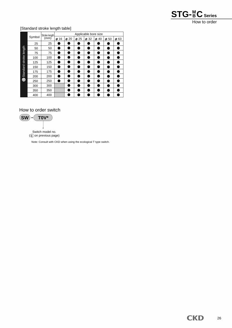
25
50
75
100
125
150
175
200
250
300
350
400
SymbolApplicable bore sizeStroke length
(mm)
25
50
75
100
125
150
175
200
250
300
350
400
16 20 25 32 40 50 63
[Standard stroke length table]
Switch model no.( on previous page)
How to order switch
SW T0V*
Sta
ndar
d st
roke
leng
thD
Note: Consult with CKD when using the ecological T type switch.
E
STG- C SeriesHow to order
MB
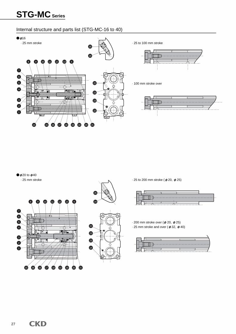
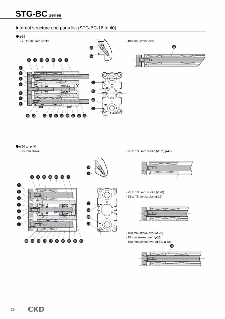
27
16
· 25 mm stroke · 25 to 100 mm stroke
· 100 mm stroke over
20 to 40
· 25 mm stroke · 25 to 200 mm stroke ( 20, 25)
· 200 mm stroke over ( 20, 25)· 25 mm stroke and over ( 32, 40)
Internal structure and parts list (STG-MC-16 to 40)
25
22
23
23
22
22
23
23
14
24
25
24
8 9 10 11 12 13 6
8 9 10 11 12 13 6
14 15 16 17 18 19 10 20 21
15 26 16 17 18 1910 20 21
7
6
5
3
2
1
4
7
6
5
3
2
1
4
STG-MC Series
28
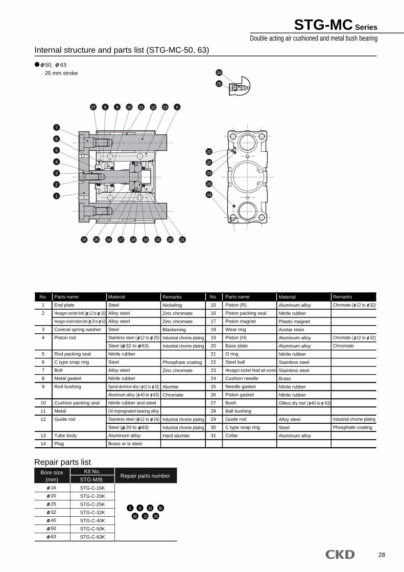
Internal structure and parts list (STG-MC-50, 63)
Parts name
End plate
Hexagon socket bolt ( 12 to 16)
Hexagon socket button bolt ( 20 to 63)
Conical spring washer
Piston rod
Rod packing seal
C type snap ring
Bolt
Metal gasket
Rod bushing
Cushion packing seal
Metal
Guide rod
Tube body
Plug
Material
Steel
Alloy steel
Alloy steel
Steel
Stainless steel ( 12 to 25)
Steel ( 32 to 63)
Nitrile rubber
Steel
Alloy steel
Nitrile rubber
Special aluminum alloy ( 12 to 32)
Aluminum alloy ( 40 to 63)
Nitrile rubber and steel
Oil impregnated bearing alloy
Stainless steel ( 12 to 16)
Steel ( 20 to 63)
Aluminum alloy
Brass or is steel.
Remarks
Nickeling
Zinc chromate
Zinc chromate
Blackening
Industrial chrome plating
Industrial chrome plating
Phosphate coating
Zinc chromate
Alumite
Chromate
Industrial chrome plating
Industrial chrome plating
Hard alumite
Material
Aluminum alloy
Nitrile rubber
Plastic magnet
Acetar resin
Aluminum alloy
Aluminum alloy
Nitrile rubber
Stainless steel
Stainless steel
Brass
Nitrile rubber
Nitrile rubber
Oilless dry met ( 40 to 63)
Alloy steel
Steel
Aluminum alloy
Remarks
Chromate ( 12 to 32)
Chromate ( 12 to 32)
Chromate
Industrial chrome plating
Phosphate coating
Parts name
Piston (R)
Piston packing seal
Piston magnet
Wear ring
Piston (H)
Base plate
O ring
Steel ball
Hexagon socket head set screw
Cushion needle
Needle gasket
Piston gasket
Bush
Ball bushing
Guide rod
C type snap ring
Collar
No.
1
2
3
4
5
6
7
8
9
10
11
12
13
14
No.
15
16
17
18
19
20
21
22
23
24
25
26
27
28
29
30
31
Bore size(mm)
Kit No.Repair parts number
Repair parts list
STG-M/B16
20
25
32
40
50
63
STG-C-16K
STG-C-20K
STG-C-25K
STG-C-32K
STG-C-40K
STG-C-50K
STG-C-63K
5 8 10 16
18 21 25
50, 63
· 25 mm stroke
7
22
22
23
23
14
24
25
27 8 9 10 11 12 13 6
6
5
4
3
2
1
15 26 16 17 18 19 10 20 21
STG-MC SeriesDouble acting air cushioned and metal bush bearing
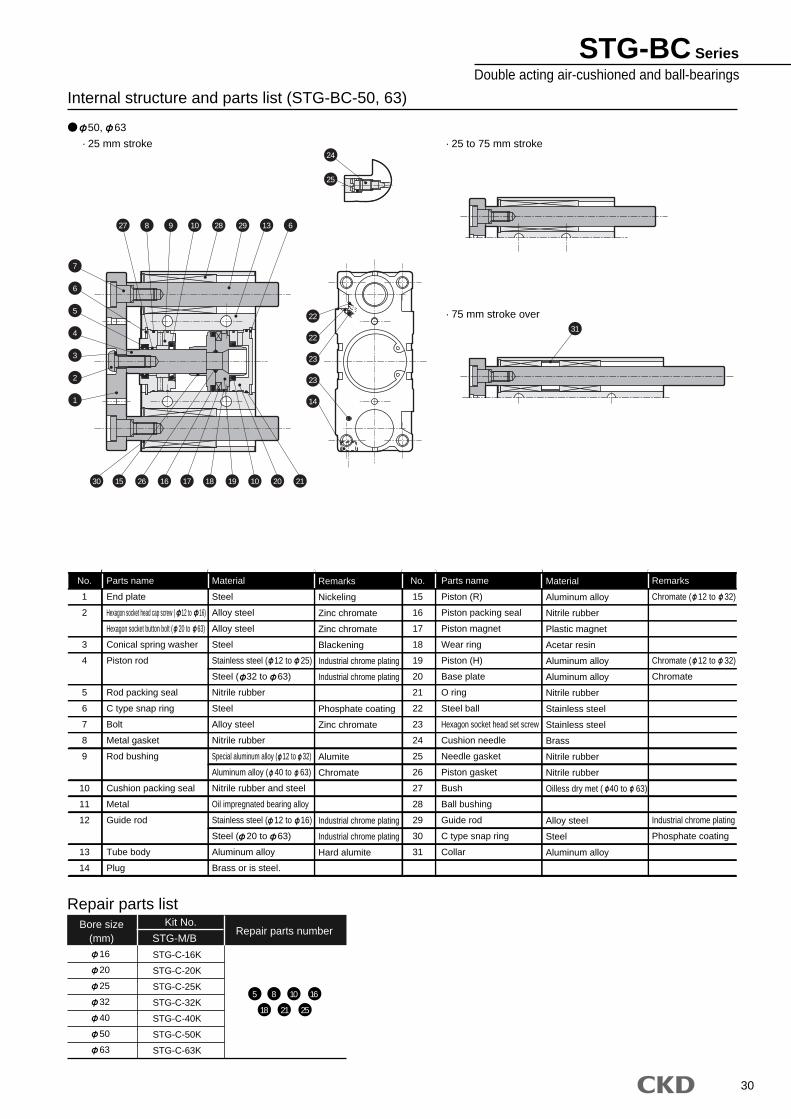
29
STG-BC Series
Internal structure and parts list (STG-BC-16 to 40)
16
· 25 to 100 mm stroke · 100 mm stroke over
20 to 40
· 25 mm stroke · 25 to 100 mm stroke ( 32, 40)
· 25 to 100 mm stroke ( 20)· 25 to 75 mm stroke ( 25)
· 100 mm stroke over ( 20)· 75 mm stroke over ( 25)· 100 mm stroke over ( 32, 40)
22
23
23
22
25
24
8 9 10 28
31
29 13 6
1430 15 16 17 18 19 10 20 21
7
25
22
23
23
14
24
8 9 10 28
31
29 13 6
6
5
4
3
2
1
30 15 26 16 17 18 10 19 20 21
7
6
5
3
2
1
4
30
Internal structure and parts list (STG-BC-50, 63)
50, 63
· 25 mm stroke · 25 to 75 mm stroke
· 75 mm stroke over
Parts name
End plate
Hexagon socket head cap screw ( 12 to 16)
Hexagon socket button bolt ( 20 to 63)
Conical spring washer
Piston rod
Rod packing seal
C type snap ring
Bolt
Metal gasket
Rod bushing
Cushion packing seal
Metal
Guide rod
Tube body
Plug
Material
Steel
Alloy steel
Alloy steel
Steel
Stainless steel ( 12 to 25)
Steel ( 32 to 63)
Nitrile rubber
Steel
Alloy steel
Nitrile rubber
Special aluminum alloy ( 12 to 32)
Aluminum alloy ( 40 to 63)
Nitrile rubber and steel
Oil impregnated bearing alloy
Stainless steel ( 12 to 16)
Steel ( 20 to 63)
Aluminum alloy
Brass or is steel.
Remarks
Nickeling
Zinc chromate
Zinc chromate
Blackening
Industrial chrome plating
Industrial chrome plating
Phosphate coating
Zinc chromate
Alumite
Chromate
Industrial chrome plating
Industrial chrome plating
Hard alumite
Material
Aluminum alloy
Nitrile rubber
Plastic magnet
Acetar resin
Aluminum alloy
Aluminum alloy
Nitrile rubber
Stainless steel
Stainless steel
Brass
Nitrile rubber
Nitrile rubber
Oilless dry met ( 40 to 63)
Alloy steel
Steel
Aluminum alloy
Remarks
Chromate ( 12 to 32)
Chromate ( 12 to 32)
Chromate
Industrial chrome plating
Phosphate coating
Parts name
Piston (R)
Piston packing seal
Piston magnet
Wear ring
Piston (H)
Base plate
O ring
Steel ball
Hexagon socket head set screw
Cushion needle
Needle gasket
Piston gasket
Bush
Ball bushing
Guide rod
C type snap ring
Collar
No.
1
2
3
4
5
6
7
8
9
10
11
12
13
14
No.
15
16
17
18
19
20
21
22
23
24
25
26
27
28
29
30
31
Bore size(mm)
Kit No.Repair parts number
Repair parts list
STG-M/B16
20
25
32
40
50
63
STG-C-16K
STG-C-20K
STG-C-25K
STG-C-32K
STG-C-40K
STG-C-50K
STG-C-63K
5 8 10 16
18 21 25
7
27 8 9 10 28
31
29 13 6
6
5
4
3
2
1
24
25
22
22
23
23
14
30 15 26 16 17 18 19 10 20 21
STG-BC SeriesDouble acting air-cushioned and ball-bearings
31
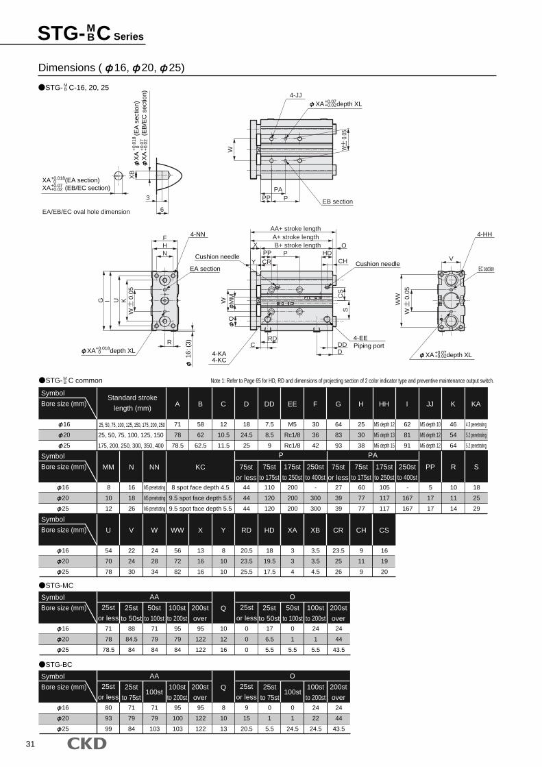
STG- C SeriesMB
Dimensions ( 16, 20, 25)
STG- C-16, 20, 25MB
STG- C common
STG-MC
16
20
25
Symbol
Bore size (mm)Standard stroke
length (mm)
25, 50, 75, 100, 125, 150
175, 200, 250, 300, 350, 400
25, 50, 75, 100, 125, 150, 175, 200, 250
16
20
25
Symbol
Bore size (mm)
JJ
M5 depth 10
M6 depth 12
M6 depth 12
I
62
81
91
HH
M5 depth 12
M5 depth 13
M6 depth 15
H
25
30
38
K
46
54
64
KA
4.3 penetrating
5.2 penetrating
5.2 penetrating
MM
8
10
12
N
16
18
26
NN
M5 penetrating
M5 penetrating
M6 penetrating
KC
8 spot face depth 4.5
9.5 spot face depth 5.5
9.5 spot face depth 5.5
-
300
300
200
200
200
P
110
120
120
44
44
44
27
39
39
PA
60
77
77
105
117
117
-
167
167
PP
5
17
17
R
10
11
14
16
20
25
Symbol
Bore size (mm) W
24
28
34
V
22
24
30
U
54
70
78
S
18
25
29
WW
56
72
82
X
13
16
16
Y
8
10
10
RD
20.5
23.5
25.5
HD
18
19.5
17.5
XA
3
3
4
XB
3.5
3.5
4.5
CR
23.5
25
26
CH
9
11
9
CS
16
19
20
16
20
25
Symbol
Bore size (mm)
95
79
84
AA
71
79
84
88
84.5
84
71
78
78.5
95
122
122
Q
10
12
16
0
0
0
17
6.5
5.5
O
0
1
5.5
24
1
5.5
24
44
43.5
A
71
78
78.5
B
58
62
62.5
C
12
10.5
11.5
D
18
24.5
25
DD
7.5
8.5
9
EE
M5
Rc1/8
Rc1/8
F
30
36
42
G
64
83
93
STG-BC
MB Note 1: Refer to Page 65 for HD, RD and dimensions of projecting section of 2 color indicator type and preventive maintenance output switch.
250st
to 400st
175st
to 250st
75st
to 175st
75st
or less
25st
to 50st
50st
to 100st
100st
to 200st
200st
over
25st
or less
25st
to 50st
50st
to 100st
100st
to 200st
200st
over
25st
or less
16
20
25
Symbol
Bore size (mm)
95
100
103
AA
71
79
103
71
79
84
80
93
99
95
122
122
Q
8
10
13
9
15
20.5
0
1
5.5
O
0
1
24.5
24
22
24.5
24
44
43.5
25st
to 75st100st
100st
to 200st
200st
over
25st
or less25st
to 75st100st
100st
to 200st
200st
over
25st
or less
250st
to 400st
175st
to 250st
75st
to 175st
75st
or less
A+ stroke lengthAA+ stroke length
B+ stroke lengthP
CR
XPP
Y
W
CRD
MM
Q
CH
OHD
DDD
SC
S
G I U K
R
NHF
EA/EB/EC oval hole dimension 6
3
XB
PPA
PP
W
WW
V
XA (EA section)XA (EB/EC section)
+0.018 0+0.07+0.02
XA
(E
A s
ectio
n)X
A
(EB
/EC
sec
tion)
+0.
018
0 +0.
07+
0.02
EB section
4-JJXA depth XL+0.07
+0.02
4-EEPiping port
Cushion needleCushion needle
4-KA4-KC
XA depth XL+0.018 0
4-NN
EA section
16: (
3)
4-HH
EC section
XA depth XL+0.07+0.02
W
0.0
5
W
0.0
5
W
0.0
5
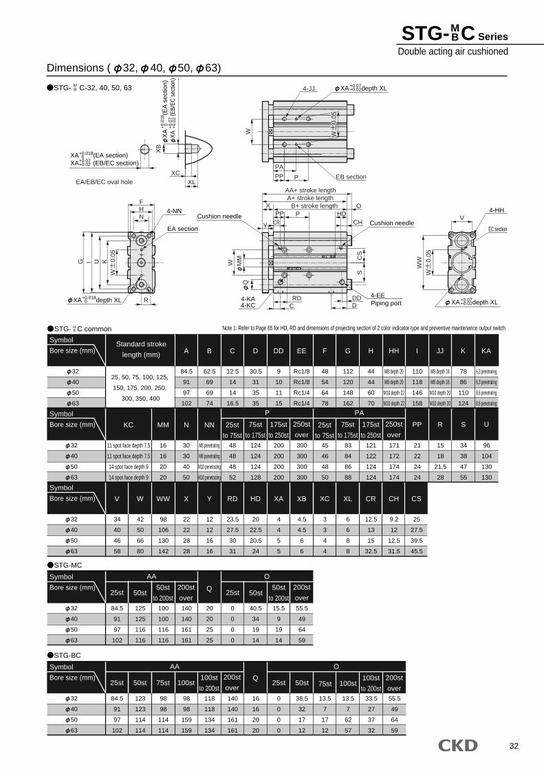
32
STG- C SeriesDouble acting air cushioned
MB
Dimensions ( 32, 40, 50, 63)
STG- C-32, 40, 50, 63MB
STG- C common
STG-MC
32
40
50
63
Symbol
Bore size (mm)Standard stroke
length (mm)
25, 50, 75, 100, 125,
150, 175, 200, 250,
300, 350, 400
32
40
50
63
Symbol
Bore size (mm)
JJ
M8 depth 16
M8 depth 16
M10 depth 20
M10 depth 20
I
110
118
146
158
HH
M8 depth 20
M8 depth 20
M10 depth 22
M10 depth 22
H
44
44
60
70
K
78
86
110
124
KA
6.3 penetrating
6.3 penetrating
8.6 penetrating
8.6 penetrating
MM
16
16
20
20
N
30
30
40
50
NN
M8 penetrating
M8 penetrating
M10 penetrating
M10 penetrating
KC
11 spot face depth 7.5
11 spot face depth 7.5
14 spot face depth 9
14 spot face depth 9
300
300
300
300
200
200
200
200
P
124
124
124
128
48
48
48
52
45
46
48
50
PA
83
84
86
88
121
122
124
124
171
172
174
174
PP
21
22
24
24
R
15
18
21.5
28
S
34
38
47
55
32
40
50
63
Symbol
Bore size (mm) WW
98
106
130
142
W
42
50
66
80
V
34
40
46
58
U
96
104
130
130
X
22
22
28
28
Y
12
12
16
16
RD
23.5
27.5
30
31
HD
20
22.5
20.5
24
XA
4
4
5
5
XB
4.5
4.5
6
6
XC
3
3
4
4
XL
6
6
8
8
CR
12.5
13
15
32.5
CH
9.2
12
12.5
31.5
CS
25
27.5
39.5
45.5
32
40
50
63
Symbol
Bore size (mm)
140
140
161
161
AA
100
100
116
116
125
125
116
116
84.5
91
97
102
20
20
25
25
Q
0
0
0
0
40.5
34
19
14
O
15.5
9
19
14
55.5
49
64
59
A
84.5
91
97
102
B
62.5
69
69
74
C
12.5
14
14
16.5
D
30.5
31
35
35
DD
9
10
11
15
EE
Rc1/8
Rc1/8
Rc1/4
Rc1/4
F
48
54
64
78
G
112
120
148
162
STG-BC
MB Note 1: Refer to Page 65 for HD, RD and dimensions of projecting section of 2 color indicator type and preventive maintenance output switch.
250st
over
175st
to 250st
75st
to 175st
25st
to 75st
50st50st
to 200st
200st
over25st 50st
50st
to 200st
200st
over25st
32
40
50
63
Symbol
Bore size (mm)
98
98
159
159
AA
98
98
114
114
123
123
114
114
84.5
91
97
102
140
140
161
161
Q
16
16
20
20
0
0
0
0
38.5
32
17
12
O
13.5
7
17
12
13.5
7
62
57
33.5
27
37
32
50st 75st 100st
118
118
134
134
100st
to 200st
200st
over25st 50st 75st 100st
100st
to 200st55.5
49
64
59
200st
over25st
250st
over
175st
to 250st
75st
to 175st
25st
to 75st
EA/EB/EC oval hole XLXC
XB
W
PA
PP P EB section
WW
VNHF
R
UIG K
Y
PP PB+ stroke lengthX
AA+ stroke length
OA+ stroke length
HDCHCR
SC
S
DDD
QM
MW
RDC
XA (EA section)XA (EB/EC section)
+0.018 0+0.07+0.02
XA
(E
A s
ectio
n)XA
(E
B/EC
sec
tion)
+0.0
18 0 +0
.07
+0.0
2
4-JJ XA depth XL+0.07+0.02
4-EEPiping port
Cushion needleCushion needle
4-KA4-KC
XA depth XL+0.018 0
4-NN
EA section
4-HH
EC section
XA depth XL+0.07+0.02
W
0.0
5
W
0.0
5
W
0.0
5W
0
.05
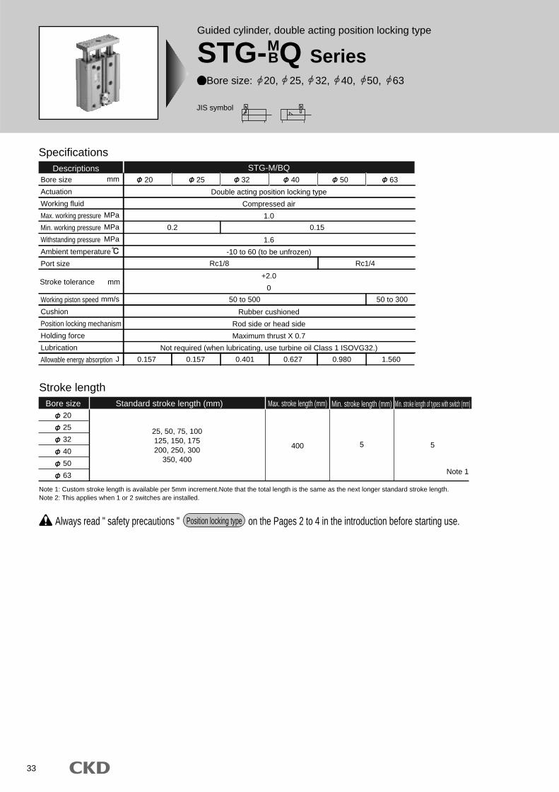
33
Specifications
Bore size
Actuation
Working fluid
Max. working pressure
Min. working pressure
Withstanding pressure
Ambient temperature
Port size
Working piston speed
Cushion
Position locking mechanism
Holding force
Lubrication
Allowable energy absorption
Double acting position locking type
Compressed air
1.0
1.6
-10 to 60 (to be unfrozen)
+2.0
0
Rubber cushioned
Rod side or head side
Maximum thrust X 0.7
Not required (when lubricating, use turbine oil Class 1 ISOVG32.)
0.2
0.157 0.157 0.401 0.627 0.980 1.560
Rc1/8 Rc1/4
50 to 500 50 to 300
0.15
Descriptions 20 25 32 40 50 63
STG-M/BQ
Stroke length
20
25
32
40
50
63
25, 50, 75, 100125, 150, 175200, 250, 300
350, 400
400 5
Bore size Standard stroke length (mm) Max. stroke length (mm) Min. stroke length (mm) Min. stroke length of types with switch (mm)
5
mm
MPa
MPa
MPa
mm/s
J
Stroke tolerance mm
Note 1: Custom stroke length is available per 5mm increment.Note that the total length is the same as the next longer standard stroke length.Note 2: This applies when 1 or 2 switches are installed.
Always read " safety precautions " on the Pages 2 to 4 in the introduction before starting use.Position locking type
Note 1
Guided cylinder, double acting position locking type
STG-MBQ Series
Bore size: 20, 25, 32, 40, 50, 63
JIS symbol
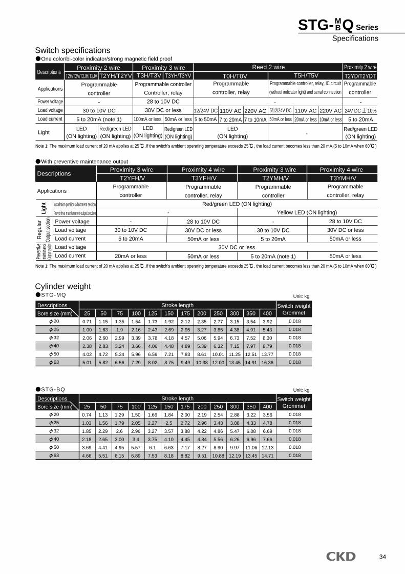
34
Switch specificationsOne color/bi-color indicator/strong magnetic field proof
Cylinder weightSTG-MQ
STG-BQ
Descriptions
Applications
Power voltage
Load voltage
Load current
Light
Reed 2 wire Proximity 2 wire
Programmable
controller
-
30 to 10V DC
5 to 20mA (note 1)
12/24V DC
5 to 50mA
110V AC
7 to 20mA
220V AC
7 to 10mA
5/12/24V DC
50mA or less
110V AC
20mA or less
220V AC
10mA or less
Programmable controller
Controller, relay
28 to 10V DC
30V DC or less
Programmable
controller, relay
Programmable
controller
Programmable controller, relay, IC circuit
(without indicator light) and serial connection
Proximity 2 wire Proximity 3 wireT2H/T2V/T2JH/T2JV T2YH/T2YV T3H/T3V T3YH/T3YV T0H/T0V T5H/T5V T2YD/T2YDT
- -
-LED
(ON lighting)
LED(ON lighting)
LED(ON lighting)
Red/green LED(ON lighting)
Red/green LED(ON lighting)
Red/green LED(ON lighting)
100mA or less 50mA or less
With preventive maintenance output
Descriptions
ApplicationsProgrammable
controller
-
30 to 10V DC
5 to 20mA
20mA or less
Programmable
controller
-
30 to 10V DC
5 to 20mA
5 to 20mA (note 1)
Programmable
controller, relay
28 to 10V DC
30V DC or less
50mA or less
50mA or less
Programmable
controller, relay
28 to 10V DC
30V DC or less
50mA or less
50mA or less
T2YFH/V T3YFH/V T2YMH/V T3YMH/V
Red/green LED (ON lighting)
30V DC or less
Yellow LED (ON lighting)-
Note 1: The maximum load current of 20 mA applies at 25 .If the switch's ambient operating temperature exceeds 25 , the load current becomes less than 20 mA.(5 to 10mA when 60 )
Note 1: The maximum load current of 20 mA applies at 25 .If the switch's ambient operating temperature exceeds 25 , the load current becomes less than 20 mA.(5 to 10mA when 60 )
Installation position adjustment section
Preventive maintenance output section
Power voltage
Load voltage
Load current
Load voltage
Load current
Reg
ular
Outp
ut se
ction
Prev
entiv
ema
intenan
ceOu
tput se
ction
Ligh
t
Proximity 3 wire Proximity 4 wire Proximity 3 wire Proximity 4 wire
20
25
32
40
50
63
Descriptions
Bore size (mm)
1.15
1.63
2.60
2.83
4.72
5.82
1.35
1.9
2.99
3.24
5.34
6.56
1.54
2.16
3.39
3.66
5.96
7.29
1.73
2.43
3.78
4.06
6.59
8.02
1.92
2.69
4.18
4.48
7.21
8.75
2.12
2.95
4.57
4.89
7.83
9.49
2.35
3.27
5.06
5.39
8.61
10.38
2.77
3.85
5.94
6.32
10.01
12.00
3.15
4.38
6.73
7.15
11.25
13.45
3.54
4.91
7.52
7.97
12.51
14.91
3.92
5.43
8.30
8.79
13.77
16.36
300 350 400Switch weight
Grommet
0.018
0.018
0.018
0.018
0.018
0.018
75 150125100 17550
0.71
1.00
2.06
2.38
4.02
5.01
25 200 250
Stroke length
20
25
32
40
50
63
Descriptions
Bore size (mm)
0.74
1.03
1.85
2.18
3.69
4.66
1.13
1.56
2.29
2.65
4.41
5.51
1.29
1.79
2.6
3.00
4.95
6.15
1.50
2.05
2.96
3.4
5.57
6.89
1.66
2.27
3.27
3.75
6.1
7.53
1.84
2.5
3.57
4.10
6.63
8.18
2.00
2.72
3.88
4.45
7.17
8.82
2.19
2.96
4.22
4.84
8.27
9.51
2.54
3.43
4.86
5.56
8.90
10.88
2.88
3.88
5.47
6.26
9.97
12.19
3.22
4.33
6.08
6.96
11.06
13.45
3.56
4.78
6.69
7.66
12.13
14.71
300 350 400Switch weight
Grommet
0.018
0.018
0.018
0.018
0.018
0.018
75 150125100 17525 50 200 250
Stroke length
Unit: kg
Unit: kg
24V DC 10%
5 to 20mA
STG- Q SeriesSpecifications
MB
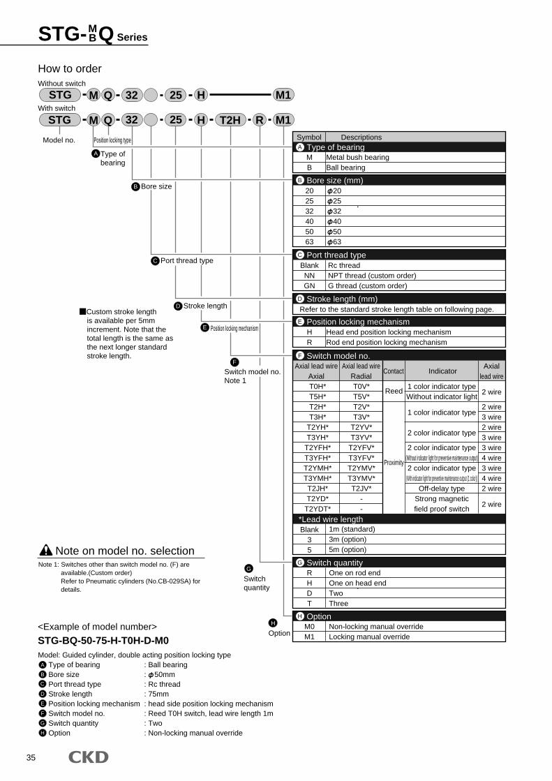
35
STG- Q SeriesMB
Symbol Descriptions
MB
Metal bush bearingBall bearing
HR
Head end position locking mechanismRod end position locking mechanism
202532405063
202532405063
Type of bearingA
Bore size (mm)B
2 wire
2 wire3 wire2 wire3 wire3 wire4 wire3 wire4 wire2 wire
2 wire
RHDT
Blank35
One on rod endOne on head endTwoThree
1m (standard)3m (option)5m (option)
Switch quantityG
BlankNNGN
Rc threadNPT thread (custom order)G thread (custom order)
Port thread typeC
Refer to the standard stroke length table on following page.Stroke length (mm)D
T0H*T5H*T2H*T3H*
T2YH*T3YH*
T2YFH*T3YFH*T2YMH*T3YMH*T2JH*T2YD*
T2YDT*
T0V*T5V*T2V*T3V*
T2YV*T3YV*
T2YFV*T3YFV*T2YMV*T3YMV*T2JV*
--
Axial lead wireAxial
Axial lead wireRadial
Contact IndicatorAxial
lead wire
Reed
Proximity
1 color indicator typeWithout indicator light
1 color indicator type
2 color indicator type
2 color indicator type(Without indicator light for preventive maintenance output)2 color indicator type
(With indicator light for preventive maintenance output (1 color))Off-delay type
Strong magneticfield proof switch
Switch model no.
*Lead wire length
F
M0M1
Non-locking manual overrideLocking manual override
OptionH
Position locking mechanismE
A
How to orderWithout switch
With switch
B Bore size
C Port thread type
D
F
Switch model no.Note 1
E Position locking mechanism
Model no. Position locking type
STG RH
H
32 25 T2H
STG M Q
M Q
32 M1
M1
25
Type ofbearing
<Example of model number>
STG-BQ-50-75-H-T0H-D-M0Model: Guided cylinder, double acting position locking type
Type of bearing : Ball bearingBore size : 50mmPort thread type : Rc threadStroke length : 75mmPosition locking mechanism : head side position locking mechanismSwitch model no. : Reed T0H switch, lead wire length 1mSwitch quantity : TwoOption : Non-locking manual override
Note on model no. selection
A
B
C
D
E
F
G
H
Note 1: Switches other than switch model no. (F) are available.(Custom order)Refer to Pneumatic cylinders (No.CB-029SA) for details.
G
Switchquantity
H
Option
Stroke lengthCustom stroke lengthis available per 5mm increment. Note that the total length is the same as the next longer standard stroke length.
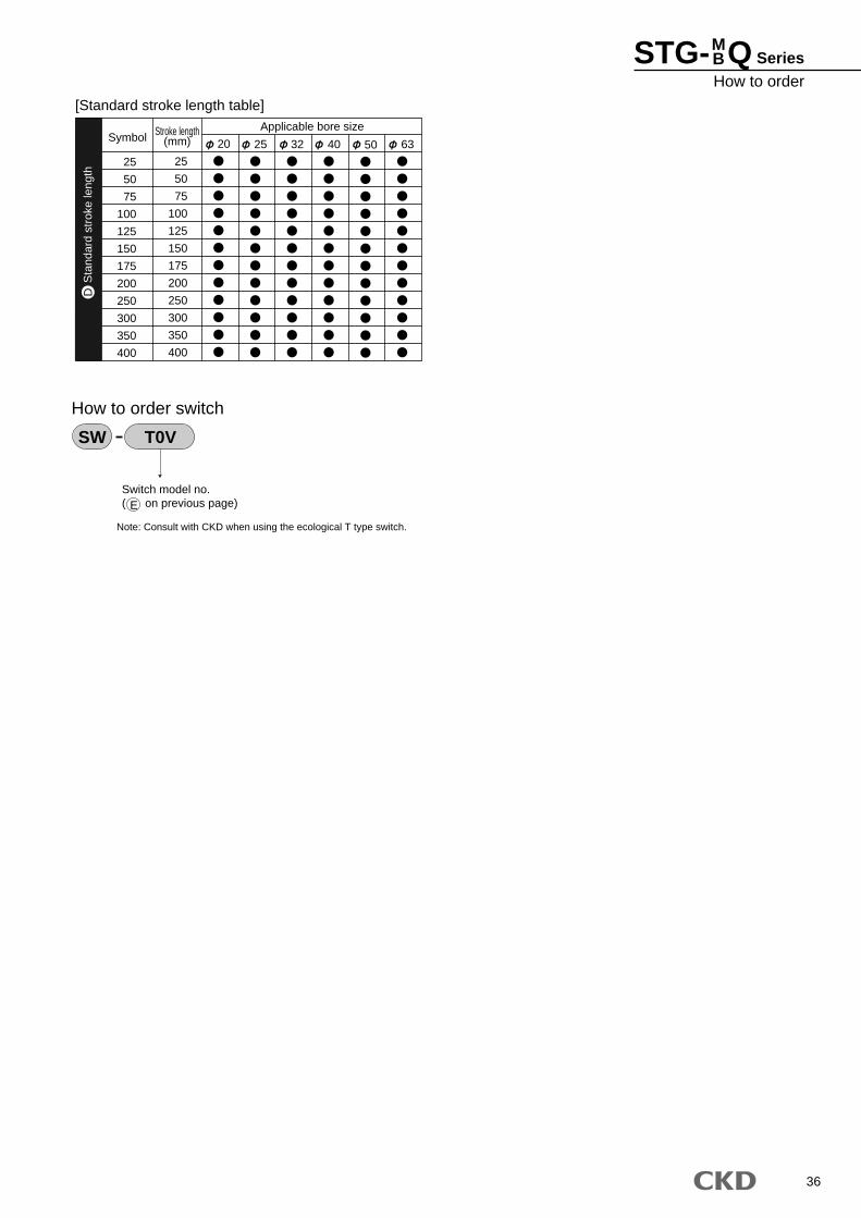
36
25
50
75
100
125
150
175
200
250
300
350
400
SymbolApplicable bore sizeStroke length
(mm)
25
50
75
100
125
150
175
200
250
300
350
400
20 25 32 40 50 63
[Standard stroke length table]
Switch model no.( on previous page)
How to order switch
SW T0V
Sta
ndar
d st
roke
leng
thD
Note: Consult with CKD when using the ecological T type switch.
E
STG- Q SeriesHow to order
MB
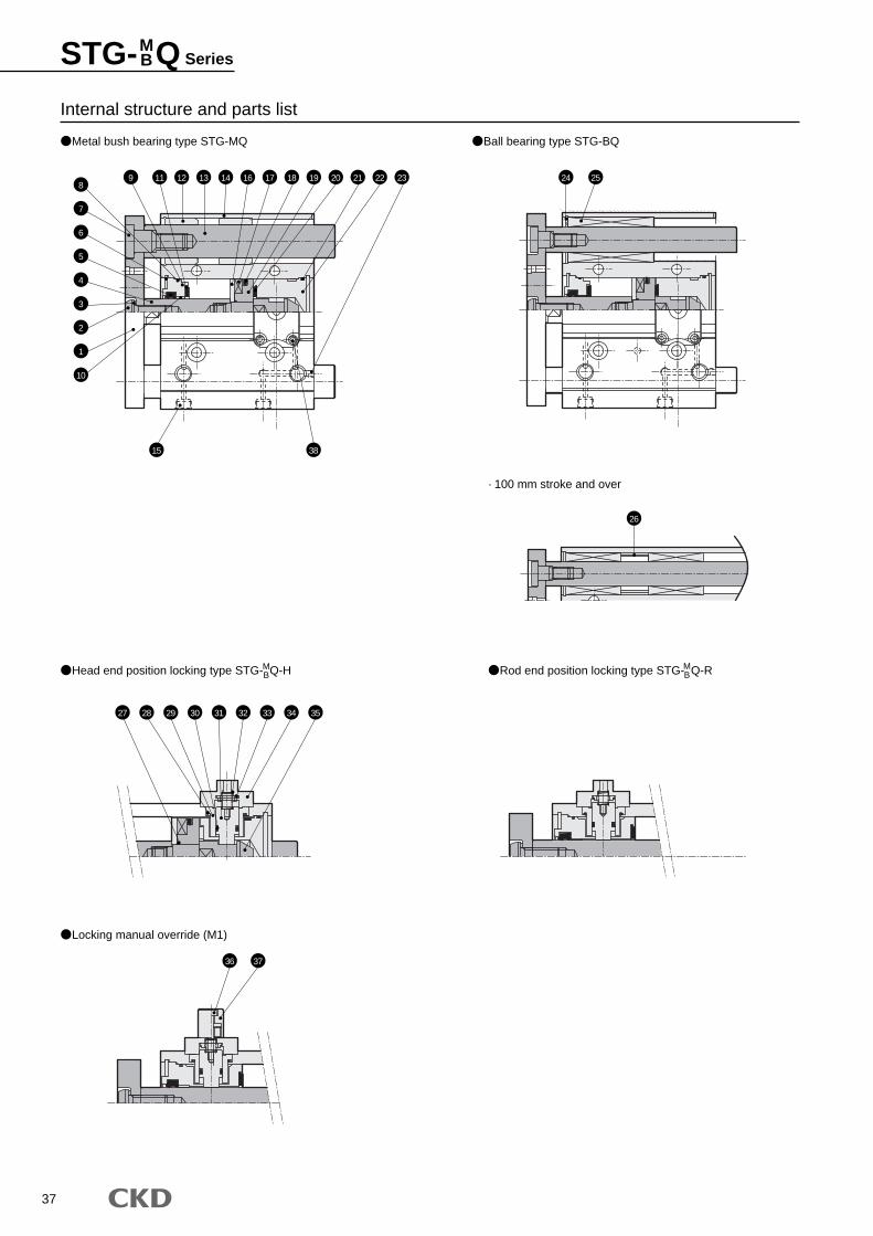
37
Metal bush bearing type STG-MQ Ball bearing type STG-BQ
Head end position locking type STG- Q-HMB
MB
Locking manual override (M1)
Rod end position locking type STG- Q-R
· 100 mm stroke and over
Internal structure and parts list
89 11 12 24
26
27 28 29 30 31 32
36 37
33 34 35
2513 14 16 17 18 19 20 21 22 23
7
6
5
4
3
2
1
15 38
10
STG- Q SeriesMB
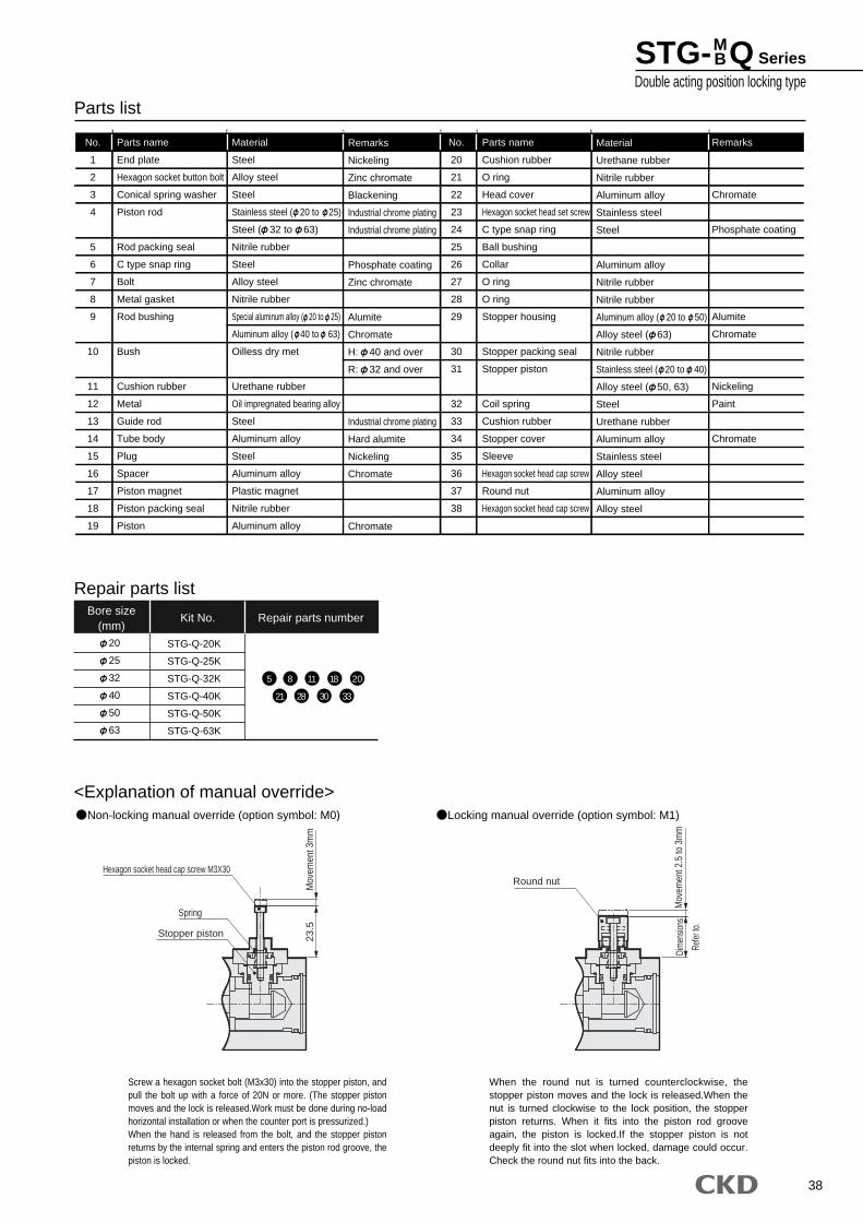
38
Parts list
Parts name
End plate
Hexagon socket button bolt
Conical spring washer
Piston rod
Rod packing seal
C type snap ring
Bolt
Metal gasket
Rod bushing
Bush
Cushion rubber
Metal
Guide rod
Tube body
Plug
Spacer
Piston magnet
Piston packing seal
Piston
Material
Steel
Alloy steel
Steel
Stainless steel ( 20 to 25)
Steel ( 32 to 63)
Nitrile rubber
Steel
Alloy steel
Nitrile rubber
Special aluminum alloy ( 20 to 25)
Aluminum alloy ( 40 to 63)
Oilless dry met
Urethane rubber
Oil impregnated bearing alloy
Steel
Aluminum alloy
Steel
Aluminum alloy
Plastic magnet
Nitrile rubber
Aluminum alloy
Remarks
Nickeling
Zinc chromate
Blackening
Industrial chrome plating
Industrial chrome plating
Phosphate coating
Zinc chromate
Alumite
Chromate
H: 40 and over
R: 32 and over
Industrial chrome plating
Hard alumite
Nickeling
Chromate
Chromate
Material
Urethane rubber
Nitrile rubber
Aluminum alloy
Stainless steel
Steel
Aluminum alloy
Nitrile rubber
Nitrile rubber
Aluminum alloy ( 20 to 50)
Alloy steel ( 63)
Nitrile rubber
Stainless steel ( 20 to 40)
Alloy steel ( 50, 63)
Steel
Urethane rubber
Aluminum alloy
Stainless steel
Alloy steel
Aluminum alloy
Alloy steel
Remarks
Chromate
Phosphate coating
Alumite
Chromate
Nickeling
Paint
Chromate
Parts name
Cushion rubber
O ring
Head cover
Hexagon socket head set screw
C type snap ring
Ball bushing
Collar
O ring
O ring
Stopper housing
Stopper packing seal
Stopper piston
Coil spring
Cushion rubber
Stopper cover
Sleeve
Hexagon socket head cap screw
Round nut
Hexagon socket head cap screw
No.
1
2
3
4
5
6
7
8
9
10
11
12
13
14
15
16
17
18
19
No.
20
21
22
23
24
25
26
27
28
29
30
31
32
33
34
35
36
37
38
Bore size(mm)
Kit No. Repair parts number
Repair parts list
<Explanation of manual override>
20
25
32
40
50
63
STG-Q-20K
STG-Q-25K
STG-Q-32K
STG-Q-40K
STG-Q-50K
STG-Q-63K
5 8 11 18
28 30 33
Non-locking manual override (option symbol: M0) Locking manual override (option symbol: M1)
Screw a hexagon socket bolt (M3x30) into the stopper piston, and pull the bolt up with a force of 20N or more. (The stopper piston moves and the lock is released.Work must be done during no-load horizontal installation or when the counter port is pressurized.)When the hand is released from the bolt, and the stopper piston returns by the internal spring and enters the piston rod groove, the piston is locked.
When the round nut is turned counterclockwise, the stopper piston moves and the lock is released.When the nut is turned clockwise to the lock position, the stopper piston returns. When it fits into the piston rod groove again, the piston is locked.If the stopper piston is not deeply fit into the slot when locked, damage could occur. Check the round nut fits into the back.
20
21
Hexagon socket head cap screw M3X30
Spring
Stopper piston 23.5
Mov
emen
t 3m
m
Round nut
Dim
ensio
ns
Refe
r to.
Mov
emen
t 2.5
to 3
mm
STG- Q SeriesDouble acting position locking type
MB
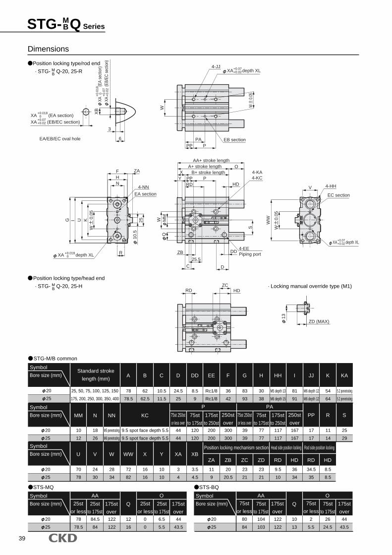
39
Dimensions
Position locking type/rod end
STG-M/B common
STS-MQ
20
25
Symbol
Bore size (mm)Standard stroke
length (mm)
25, 50, 75, 100, 125, 150
175, 200, 250, 300, 350, 400
20
25
Symbol
Bore size (mm)
JJ
M6 depth 12
M6 depth 12
I
81
91
HH
M5 depth 13
M6 depth 15
H
30
38
K
54
64
KA
5.2 penetrating
5.2 penetrating
MM
10
12
N
18
26
NN
M5 penetrating
M6 penetrating
KC
9.5 spot face depth 5.5
9.5 spot face depth 5.5
300
300
200
200
P
120
120
44
44
39
39
PA
77
77
117
117
167
167
PP
17
17
R
11
14
20
25
Symbol
Bore size (mm) W
28
34
V
24
30
U
70
78
S
25
29
WW
72
82
X
16
16
Y
10
10
XA
3
4
XB
3.5
4.5
ZA
11
9
ZB
20
20.5
ZC
Position locking mechanism section Head side position locking Rod side position locking
23
21
ZD
23
21
RD HD RD HD
9.5
10
36
34
34.5
35
8.5
8.5
20
25
Symbol
Bore size (mm)
AA
84.5
84
78
78.5
122
122
Q
12
16
0
0
6.5
5.5
O
44
43.5
A
78
78.5
B
62
62.5
C
10.5
11.5
D
24.5
25
DD
8.5
9
EE
Rc1/8
Rc1/8
F
36
42
G
83
93
STS-BQ
250st
over
250st
over
175st
to 250st
75st
to 175st
75st 250st
or less over
25st
to 175st
175st
over
25st
or less
25st
to 175st
175st
over
25st
or less20
25
Symbol
Bore size (mm)
AA
104
103
80
84
122
122
Q
10
13
2
5.5
26
24.5
O
44
43.5
75st
to 175st
175st
over
75st
or less75st
to 175st
175st
over
75st
or less
175st
to 250st
75st
to 175st
75st 250st
or less over
· STG- Q-20, 25-RMB
Position locking type/head end
· STG- Q-20, 25-H · Locking manual override type (M1)MB
WW
V
6
3
XB
4-HH
EC section
4-JJ
EB sectionP
PAPP
W
EA section
R
4-NNN
FH
G I U K
QW M
M
4-KA4-KCPP P
B+ stroke lengthA+ stroke length
AA+ stroke length
YX
O
S
HD
4-EEPiping portDD
C D
RD
25.5
ZA
ZB
10.5
25
RD HDZC
T0H
CK
D
T0H
CK
D
13
ZD (MAX)
XA
(EA
sect
ion)
XA
(EB/
EC s
ectio
n)
+0.
018
0+
0.07
+0.
02
XA (EA section)XA (EB/EC section)
+0.0180
+0.07+0.02
XA depth XL+0.07+0.02
XA depth XL+0.0180
XA depth XL+0.07+0.02
EA/EB/EC oval hole
W
0.0
5
W
0.0
5
W
0.0
5
STG- Q SeriesMB
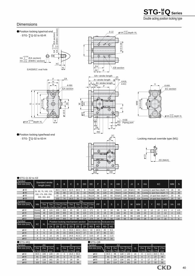
40
XA depth XL+0.018 0
EA/EB/EC oval hole PA
PP P
4-JJ
EB section
UI
R
G
NHF
CC
CDD
D
PP PYX B+ stroke length
A+ stroke length OAA+ stroke length
MM
WQ
S
RD
HD
V
WW
4-HHEA section EC section
4-EEPiping port
K
XB
XC
XL
4-KA4-KC
4-NN
10.5
ZE
ZB
ZA
RD HD
ZC
ZF
CK
D
T0H
*
CK
D
T0H
*
13
ZD (MAX)
XA depth XL+0.07+0.02
XA depth XL+0.07+0.02
XA (EA section)XA (EB/EC section)
+0.0180
+0.07+0.02
XA
(E
A s
ectio
n)X
A
(
EB
/EC
sec
tion)
+0.
018
0+
0.07
+0.
02
W
0.0
5
W
0.0
5
W
0.0
5
Dimensions
Position locking type/rod end
STG-Q-32 to 63
STG-MQ
32
40
50
63
SymbolBore size (mm)
Standard strokelength (mm)
25, 50, 75, 100, 125,
150, 175, 200, 250,
300, 350, 400
32
40
50
63
SymbolBore size (mm)
JJ
M8 depth 16
M8 depth 16
M10 depth 20
M10 depth 20
I
110
118
146
158
HH
M8 depth 20
M8 depth 20
M10 depth 22
M10 depth 22
H
44
44
60
70
K
78
86
110
124
KA
6.3 penetrating
6.3 penetrating
8.6 penetrating
8.6 penetrating
KC
11 spot face depth 7.5
11 spot face depth 7.5
14 spot face depth 9
14 spot face depth 9
MM
16
16
20
20
N
30
30
40
50
NN
M8 penetrating
M8 penetrating
M10 penetrating
M10 penetrating
300
300
300
300
200
200
200
200
P
124
124
124
128
48
48
48
52
45
46
48
50
PA
83
84
86
88
121
122
124
124
171
172
174
174
PP
21
22
24
24
R
15
18
21.5
28
S
34
38
47
55
32
40
50
63
SymbolBore size (mm)
W
42
50
66
80
V
34
40
46
58
U
96
104
130
130
WW
98
106
130
142
X
22
22
28
28
Y
12
12
16
16
RD
10
13
13.5
14
HD XA XB
XC XL
8.5
12
11.5
16
4
4
5
5
4.5
4.5
6
6
3
3
4
4
6
6
8
8
ZA10
12
12
11.5
ZB21
26
25
25
ZC21
23
23
25.5
ZD
Position locking mechanism section Head side position locking Rod side position locking
23.5
23.5
24.5
24
ZE33.5
41.5
41.5
41.5
ZF26.5
27
27
27
RD10
13
13.5
14
HD34.5
37
37
40
RD35
40
39
39
HD8.5
12
11.5
16
32
40
50
63
SymbolBore size (mm)
AA
100
100
116
116
84.5
91
97
102
140
140
161
161
Q
20
20
25
25
0
0
0
0
15.5
9
19
14
O
55.5
49
64
59
A
84.5
91
97
102
B
62.5
69
69
74
C
12.5
14
14
16.5
D
30.5
31
35
35
DD
9
10
11
15
EE
Rc1/8
Rc1/8
Rc1/4
Rc1/4
F
48
54
64
78
G
112
120
148
162
STG-QB
275st
over
275st
over
175st
to 275st
75st
to 175st
75st
or less
25st
to 175st
175st
over
25st
or less
25st
to 175st
175st
over
25st
or less
32
40
50
63
SymbolBore size (mm)
AA
96
98
114
114
84.5
91
97
102
140
140
161
161
Q
16
16
20
20
0
0
0
0
11.5
7
17
12
O
55.5
49
64
59
25st
to 75st
175st
over
25st
or less
25st
to 75st
118
118
134
134
33.5
27
37
32
75st
to 175st
75st
to 175st
175st
over
25st
or less
175st
to 275st
75st
to 175st
75st
or less
· STG- Q-32 to 63-RMB
Position locking type/head end
· STG- Q-32 to 63-H · Locking manual override type (M1)MB
STG- Q SeriesDouble acting position locking type
MB
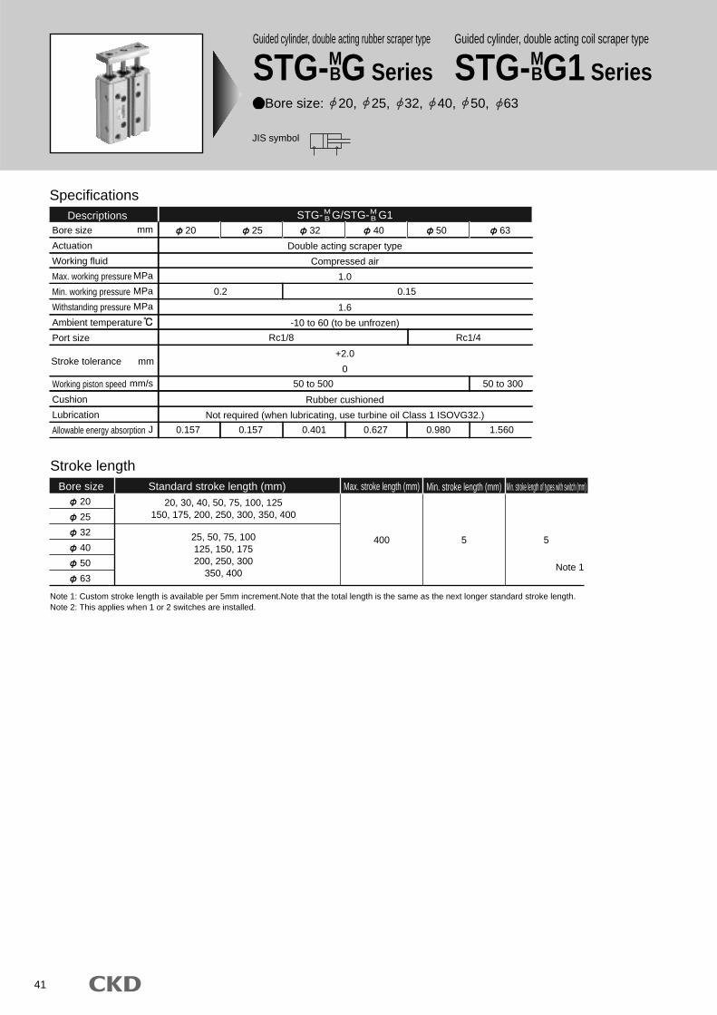
41
Guided cylinder, double acting rubber scraper type
STG-MBG Series
Bore size: 20, 25, 32, 40, 50, 63
JIS symbol
Specifications
Bore size
Actuation
Working fluid
Max. working pressure
Min. working pressure
Withstanding pressure
Ambient temperature
Port size
Working piston speed
Cushion
Lubrication
Allowable energy absorption
Double acting scraper type
Compressed air
1.0
1.6
-10 to 60 (to be unfrozen)
+2.0
0
Rubber cushioned
Not required (when lubricating, use turbine oil Class 1 ISOVG32.)
0.2
0.157 0.157 0.401 0.627 0.980 1.560
Rc1/8 Rc1/4
50 to 500 50 to 300
0.15
Descriptions 20 25 32 40 50 63
Stroke length
20
25
32
40
50
63
20, 30, 40, 50, 75, 100, 125150, 175, 200, 250, 300, 350, 400
25, 50, 75, 100125, 150, 175200, 250, 300
350, 400
400 5
Bore size Standard stroke length (mm) Max. stroke length (mm) Min. stroke length (mm) Min. stroke length of types with switch (mm)
5
Note 1
mm
MPa
MPa
MPa
mm/s
J
Stroke tolerance mm
Note 1: Custom stroke length is available per 5mm increment.Note that the total length is the same as the next longer standard stroke length.Note 2: This applies when 1 or 2 switches are installed.
STG- G/STG- G1MB
MB
Guided cylinder, double acting coil scraper type
STG-MBG1 Series
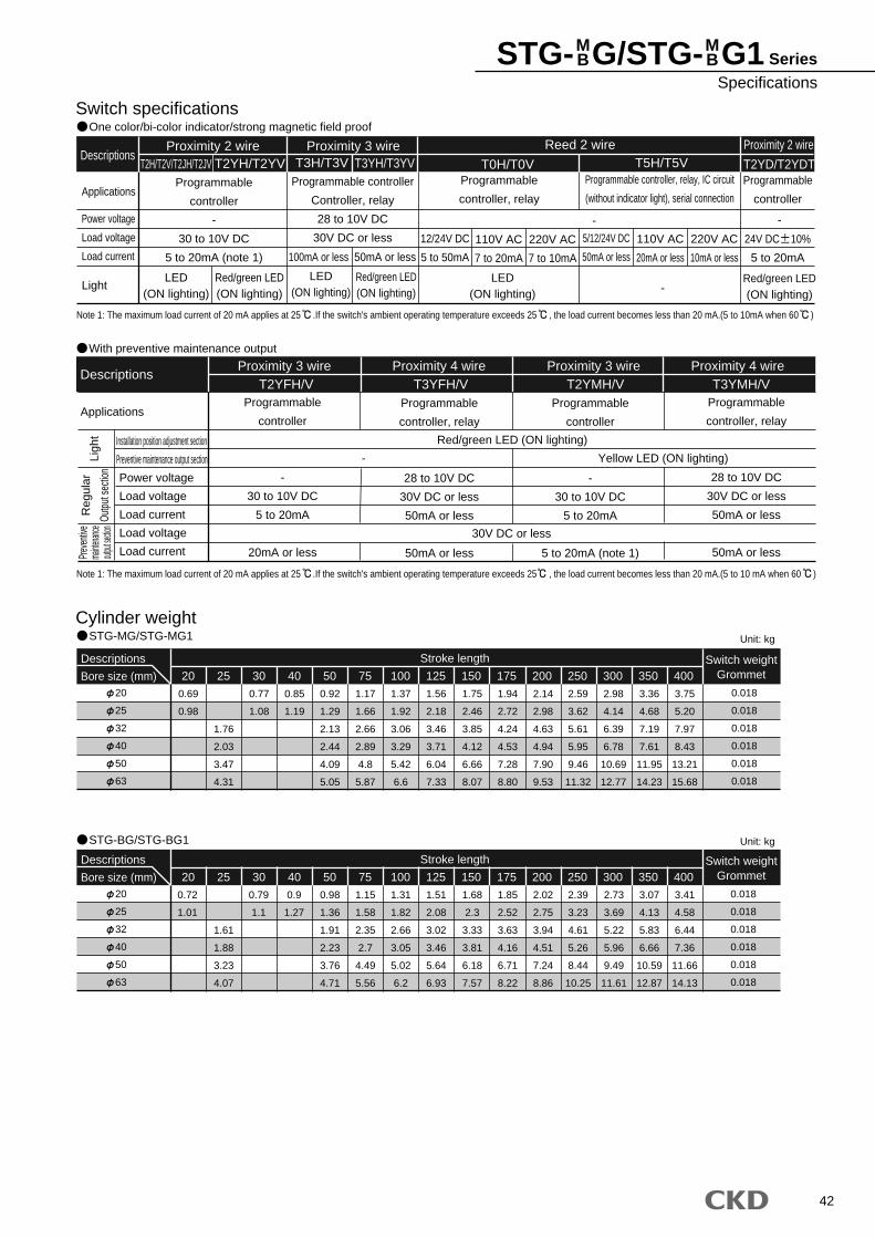
42
STG- G/STG- G1 SeriesSpecifications
MB
MB
Switch specificationsOne color/bi-color indicator/strong magnetic field proof
Descriptions
Applications
Power voltage
Load voltage
Load current
Light
Reed 2 wire Proximity 2 wire
Programmable
controller
-
30 to 10V DC
5 to 20mA (note 1)
12/24V DC
5 to 50mA
110V AC
7 to 20mA
220V AC
7 to 10mA
5/12/24V DC
50mA or less
110V AC
20mA or less
220V AC
10mA or less
Programmable controller
Controller, relay
28 to 10V DC
30V DC or less
Programmable
controller, relay
Programmable
controller
Programmable controller, relay, IC circuit
(without indicator light), serial connection
Proximity 2 wire Proximity 3 wireT2H/T2V/T2JH/T2JV T2YH/T2YV T3H/T3V T3YH/T3YV T0H/T0V T5H/T5V T2YD/T2YDT
- -
-LED
(ON lighting)
LED(ON lighting)
LED(ON lighting)
Red/green LED(ON lighting)
Red/green LED(ON lighting)
Red/green LED(ON lighting)
100mA or less 50mA or less
With preventive maintenance output
Descriptions
ApplicationsProgrammable
controller
-
30 to 10V DC
5 to 20mA
20mA or less
Programmable
controller
-
30 to 10V DC
5 to 20mA
5 to 20mA (note 1)
Programmable
controller, relay
28 to 10V DC
30V DC or less
50mA or less
50mA or less
Programmable
controller, relay
28 to 10V DC
30V DC or less
50mA or less
50mA or less
T2YFH/V T3YFH/V T2YMH/V T3YMH/V
Red/green LED (ON lighting)
30V DC or less
Yellow LED (ON lighting)-
Note 1: The maximum load current of 20 mA applies at 25 .If the switch's ambient operating temperature exceeds 25 , the load current becomes less than 20 mA.(5 to 10mA when 60 )
Note 1: The maximum load current of 20 mA applies at 25 .If the switch's ambient operating temperature exceeds 25 , the load current becomes less than 20 mA.(5 to 10 mA when 60 )
Installation position adjustment section
Preventive maintenance output section
Power voltage
Load voltage
Load current
Load voltage
Load current
Reg
ular
Outp
ut se
ction
Prev
entiv
ema
intenan
ceout
put se
ction
Ligh
t
Proximity 3 wire Proximity 4 wire Proximity 3 wire Proximity 4 wire
Cylinder weightSTG-MG/STG-MG1
STG-BG/STG-BG1
20
25
32
40
50
63
Descriptions
Bore size (mm)
0.69
0.98
1.76
2.03
3.47
4.31
0.77
1.08
0.85
1.19
0.92
1.29
2.13
2.44
4.09
5.05
1.17
1.66
2.66
2.89
4.8
5.87
1.37
1.92
3.06
3.29
5.42
6.6
1.56
2.18
3.46
3.71
6.04
7.33
1.75
2.46
3.85
4.12
6.66
8.07
1.94
2.72
4.24
4.53
7.28
8.80
2.14
2.98
4.63
4.94
7.90
9.53
2.59
3.62
5.61
5.95
9.46
11.32
2.98
4.14
6.39
6.78
10.69
12.77
3.36
4.68
7.19
7.61
11.95
14.23
3.75
5.20
7.97
8.43
13.21
15.68
20 25 350 400Switch weight
Grommet
0.018
0.018
0.018
0.018
0.018
0.018
100 175150125 20030 40 50 75 250 300
Stroke length
20
25
32
40
50
63
Descriptions
Bore size (mm)
0.72
1.01
1.61
1.88
3.23
4.07
0.79
1.1
0.9
1.27
0.98
1.36
1.91
2.23
3.76
4.71
1.15
1.58
2.35
2.7
4.49
5.56
1.31
1.82
2.66
3.05
5.02
6.2
1.51
2.08
3.02
3.46
5.64
6.93
1.68
2.3
3.33
3.81
6.18
7.57
1.85
2.52
3.63
4.16
6.71
8.22
2.02
2.75
3.94
4.51
7.24
8.86
2.39
3.23
4.61
5.26
8.44
10.25
2.73
3.69
5.22
5.96
9.49
11.61
3.07
4.13
5.83
6.66
10.59
12.87
3.41
4.58
6.44
7.36
11.66
14.13
20 25 350 400Switch weight
Grommet
0.018
0.018
0.018
0.018
0.018
0.018
100 175150125 20030 40 50 75 250 300
Stroke length
Unit: kg
Unit: kg
24V DC 10%
5 to 20mA
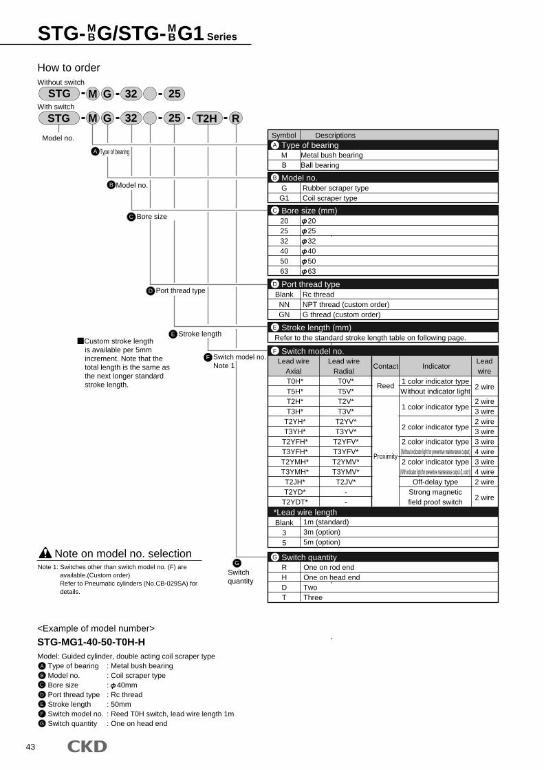
43
STG- G/STG- G1 SeriesMB
MB
Symbol Descriptions
MB
Metal bush bearingBall bearing
202532405063
202532405063
Type of bearingA
Bore size (mm)C
2 wire
2 wire3 wire2 wire3 wire3 wire4 wire3 wire4 wire2 wire
2 wire
RHDT
Blank35
One on rod endOne on head endTwoThree
1m (standard)3m (option)5m (option)
Switch quantityG
BlankNNGN
Rc threadNPT thread (custom order)G thread (custom order)
Port thread typeD
GG1
Rubber scraper typeCoil scraper type
Model no.B
Refer to the standard stroke length table on following page.Stroke length (mm)E
T0H*T5H*T2H*T3H*
T2YH*T3YH*
T2YFH*T3YFH*T2YMH*T3YMH*T2JH*T2YD*
T2YDT*
T0V*T5V*T2V*T3V*
T2YV*T3YV*
T2YFV*T3YFV*T2YMV*T3YMV*T2JV*
--
Lead wireAxial
Lead wireRadial
Contact IndicatorLeadwire
Reed
Proximity
1 color indicator typeWithout indicator light
1 color indicator type
2 color indicator type
2 color indicator type(Without indicator light for preventive maintenance output)2 color indicator type
(With indicator light for preventive maintenance output (1 color))Off-delay type
Strong magneticfield proof switch
Switch model no.
*Lead wire length
F
A
How to orderWithout switch
With switch
C Bore size
D Port thread type
E Stroke length
F Switch model no.Note 1
Model no.
STG R32 25 T2H
STG 32 25
<Example of model number>
STG-MG1-40-50-T0H-HModel: Guided cylinder, double acting coil scraper type
Type of bearing : Metal bush bearingModel no. : Coil scraper typeBore size : 40mmPort thread type : Rc threadStroke length : 50mmSwitch model no. : Reed T0H switch, lead wire length 1mSwitch quantity : One on head end
Note on model no. selection
A
B
C
D
E
F
G
Note 1: Switches other than switch model no. (F) are available.(Custom order)Refer to Pneumatic cylinders (No.CB-029SA) for details.
G
Switchquantity
M G
M G
Type of bearing
B Model no.
Custom stroke lengthis available per 5mm increment. Note that the total length is the same as the next longer standard stroke length.
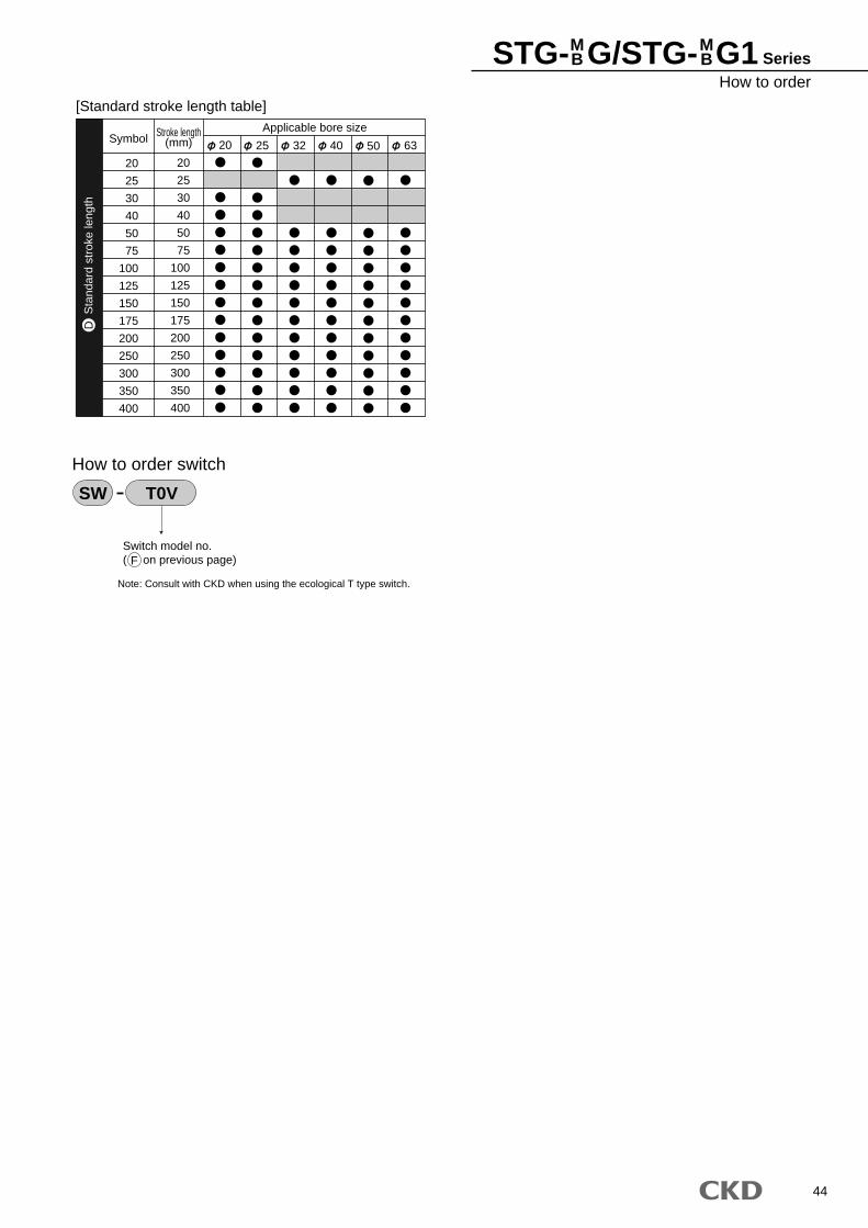
44
STG- G/STG- G1 SeriesHow to order
MB
MB
20
25
30
40
50
75
100
125
150
175
200
250
300
350
400
SymbolApplicable bore sizeStroke length
(mm)
20
25
30
40
50
75
100
125
150
175
200
250
300
350
400
20 25 32 40 50 63
[Standard stroke length table]
Switch model no.( on previous page)
How to order switch
SW T0V
Sta
ndar
d st
roke
leng
thD
Note: Consult with CKD when using the ecological T type switch.
F
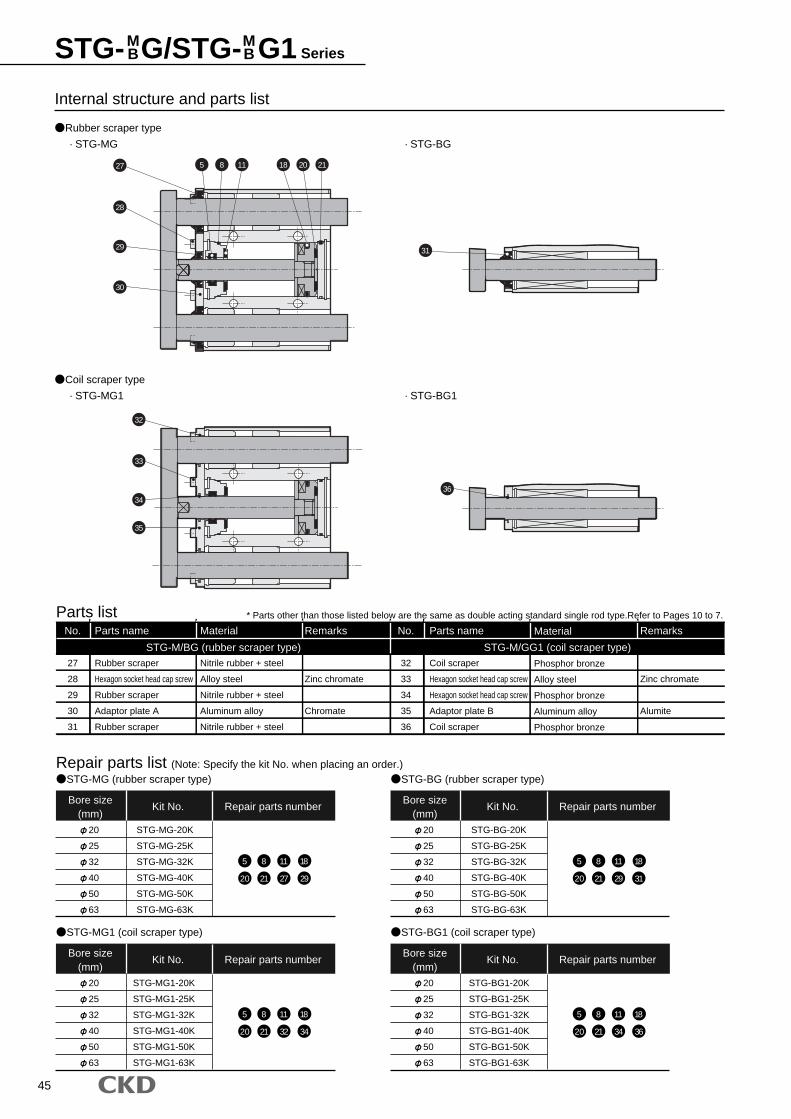
45
Rubber scraper type
· STG-MG
Coil scraper type
· STG-MG1
· STG-BG
· STG-BG1
Internal structure and parts list
Parts name Material
Zinc chromate
Chromate
Phosphor bronze
Alloy steel
Phosphor bronze
Aluminum alloy
Phosphor bronze
Zinc chromate
Alumite
Coil scraper
Hexagon socket head cap screw
Hexagon socket head cap screw
Adaptor plate B
Coil scraper
No.
32
33
34
35
36
27
28
29
30
31
Rubber scraper
Hexagon socket head cap screw
Rubber scraper
Adaptor plate A
Rubber scraper
Nitrile rubber + steel
Alloy steel
Nitrile rubber + steel
Aluminum alloy
Nitrile rubber + steel
STG-M/BG (rubber scraper type) STG-M/GG1 (coil scraper type)
Remarks No. Parts name Material Remarks
Bore size(mm)
Kit No. Repair parts number
Repair parts list (Note: Specify the kit No. when placing an order.)
20
25
32
40
50
63
STG-MG-20K
STG-MG-25K
STG-MG-32K
STG-MG-40K
STG-MG-50K
STG-MG-63K
5 8 11 18
20 21 27 29
STG-MG (rubber scraper type)
Bore size(mm)
Kit No. Repair parts number
20
25
32
40
50
63
STG-BG-20K
STG-BG-25K
STG-BG-32K
STG-BG-40K
STG-BG-50K
STG-BG-63K
5 8 11 18
20 21 29 31
STG-BG (rubber scraper type)
Bore size(mm)
Kit No. Repair parts number
20
25
32
40
50
63
STG-MG1-20K
STG-MG1-25K
STG-MG1-32K
STG-MG1-40K
STG-MG1-50K
STG-MG1-63K
5 8 11 18
20 21 32 34
STG-MG1 (coil scraper type)
Bore size(mm)
Kit No. Repair parts number
20
25
32
40
50
63
STG-BG1-20K
STG-BG1-25K
STG-BG1-32K
STG-BG1-40K
STG-BG1-50K
STG-BG1-63K
5 8 11 18
20 21 34 36
STG-BG1 (coil scraper type)
Parts list * Parts other than those listed below are the same as double acting standard single rod type.Refer to Pages 10 to 7.
27
28
32
33
34
35
29
30
5 8 11 18 20 21
31
36
STG- G/STG- G1 SeriesMB
MB
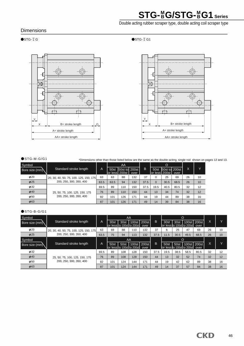
46
STG- G/STG- G1 SeriesDouble acting rubber scraper type, double acting coil scraper type
MB
MB
STG- G
DimensionsMB STG- G1M
B
STG-M-G/G1
20
25
32
40
50
63
Symbol
Bore size (mm)
20, 30, 40, 50, 75, 100, 125, 150, 175200, 250, 300, 350, 400
25, 50, 75, 100, 125, 150, 175200, 250, 300, 350, 400
63
63.5
69.5
76
82
87
63
63.5
89
89
101
101
88
94
110
110
126
126
132
132
150
150
171
171
37
37.5
37.5
44
44
49
0
0
19.5
13
19
14
25
30.5
40.5
34
44
39
69
68.5
80.5
74
89
84
26
26
32
32
38
38
10
10
12
12
16
16
AA50st
or less50st to200st
200stover
OX Y50st
or less50st to200st
200stover
A BStandard stroke length
STG-B-G/G1
20
25
Symbol
Bore size (mm)
20, 30, 40, 50, 75, 100, 125, 150, 175200, 250, 300, 350, 400
25, 50, 75, 100, 125, 150, 175200, 250, 300, 350, 400
63
63.5
69
75
88
94
110
113
128
132
132
150
37
37.5
37.5
6
11.5
19.5
25
30.5
38.5
47
49.5
58.5
69
68.5
80.5
26
26
32
10
10
12
32
40
50
63
69.5
76
82
87
89
89
101
101
108
108
124
124
128
128
144
144
150
150
171
171
37.5
44
44
49
19.5
13
19
14
38.5
32
42
37
58.5
52
62
57
80.5
74
89
84
32
32
38
38
12
12
16
16
AA30st
or less30st
to 100st100stto 200st
200stover
OX Y30st
or less30st
to 100st100stto 200st
200stover
A BStandard stroke length
Symbol
Bore size (mm)
AA50st
or less50st
to 100st100stto 200st
200stover
OX Y50st
or less50st
to 100st100stto 200st
200stover
A BStandard stroke length
AA+ stroke length
X
Y
B+ stroke length
AA+ stroke length
X
Y
B+ stroke lengthO
A+ stroke length A+ stroke length
*Dimensions other than those listed below are the same as the double-acting, single rod shown on pages 12 and 13.
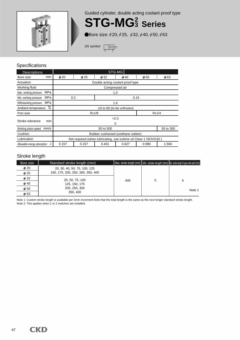
47
Specifications
Bore size
Actuation
Working fluid
Max. working pressure
Min. working pressure
Withstanding pressure
Ambient temperature
Port size
Working piston speed
Cushion
Lubrication
Allowable energy absorption
Double acting coolant proof type
Compressed air
1.0
1.6
-10 to 60 (to be unfrozen)
+2.0
0
Rubber cushioned (urethane rubber)
Not required (when lubricating, use turbine oil Class 1 ISOVG32.)
0.2
0.157 0.157 0.401 0.627 0.980 1.560
Rc1/8 Rc1/4
50 to 500 50 to 300
0.15
Descriptions20 25 32 40 50 63
STG-MG
Stroke length
20
25
32
40
50
63
20, 30, 40, 50, 75, 100, 125150, 175, 200, 250, 300, 350, 400
25, 50, 75, 100125, 150, 175200, 250, 300
350, 400
400 5
Bore size Standard stroke length (mm) Max. stroke length (mm) Min. stroke length (mm) Min. stroke length of types with switch (mm)
5
Note 1
mm
MPa
MPa
MPa
mm/s
J
Stroke tolerance mm
Note 1: Custom stroke length is available per 5mm increment.Note that the total length is the same as the next longer standard stroke length.Note 2: This applies when 1 or 2 switches are installed.
23
Guided cylinder, double acting coolant proof type
STG-MG23 Series
Bore size: 20, 25, 32, 40, 50, 63
JIS symbol
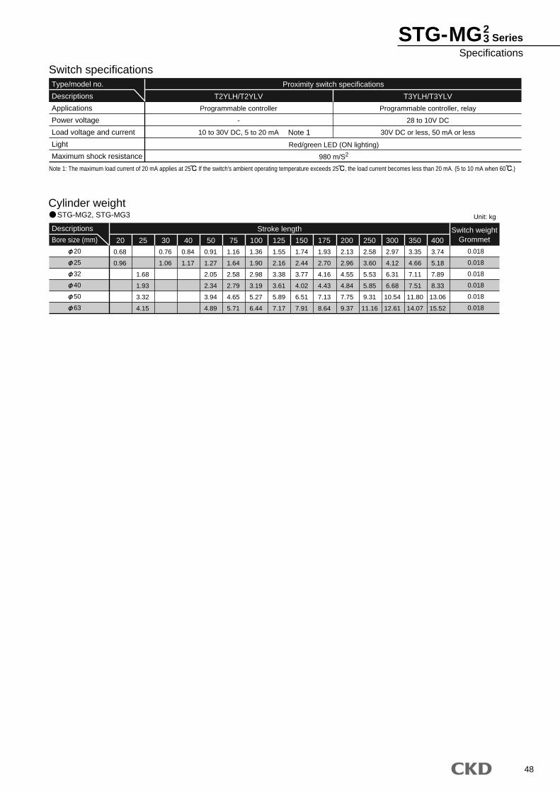
48
STG-MG23 Series
Specifications
Cylinder weightSTG-MG2, STG-MG3
20
25
32
40
50
63
Descriptions
Bore size (mm)
0.68
0.96
1.68
1.93
3.32
4.15
0.76
1.06
0.84
1.17
0.91
1.27
2.05
2.34
3.94
4.89
1.16
1.64
2.58
2.79
4.65
5.71
1.36
1.90
2.98
3.19
5.27
6.44
1.55
2.16
3.38
3.61
5.89
7.17
1.74
2.44
3.77
4.02
6.51
7.91
1.93
2.70
4.16
4.43
7.13
8.64
2.13
2.96
4.55
4.84
7.75
9.37
2.58
3.60
5.53
5.85
9.31
11.16
2.97
4.12
6.31
6.68
10.54
12.61
3.35
4.66
7.11
7.51
11.80
14.07
3.74
5.18
7.89
8.33
13.06
15.52
20 300 350 400Switch weight
Grommet
0.018
0.018
0.018
0.018
0.018
0.018
75 150125100 17525 30 40 50 200 250
Stroke length
Unit: kg
T2YLH/T2YLV T3YLH/T3YLV
Type/model no.
Descriptions
Applications
Power voltage
Load voltage and current
Light
Maximum shock resistance
Switch specificationsProximity switch specifications
Programmable controller
-
10 to 30V DC, 5 to 20 mA
Programmable controller, relay
28 to 10V DC
30V DC or less, 50 mA or less
Red/green LED (ON lighting)
980 m/S2
Note 1: The maximum load current of 20 mA applies at 25 . If the switch's ambient operating temperature exceeds 25 , the load current becomes less than 20 mA. (5 to 10 mA when 60 .)
Note 1
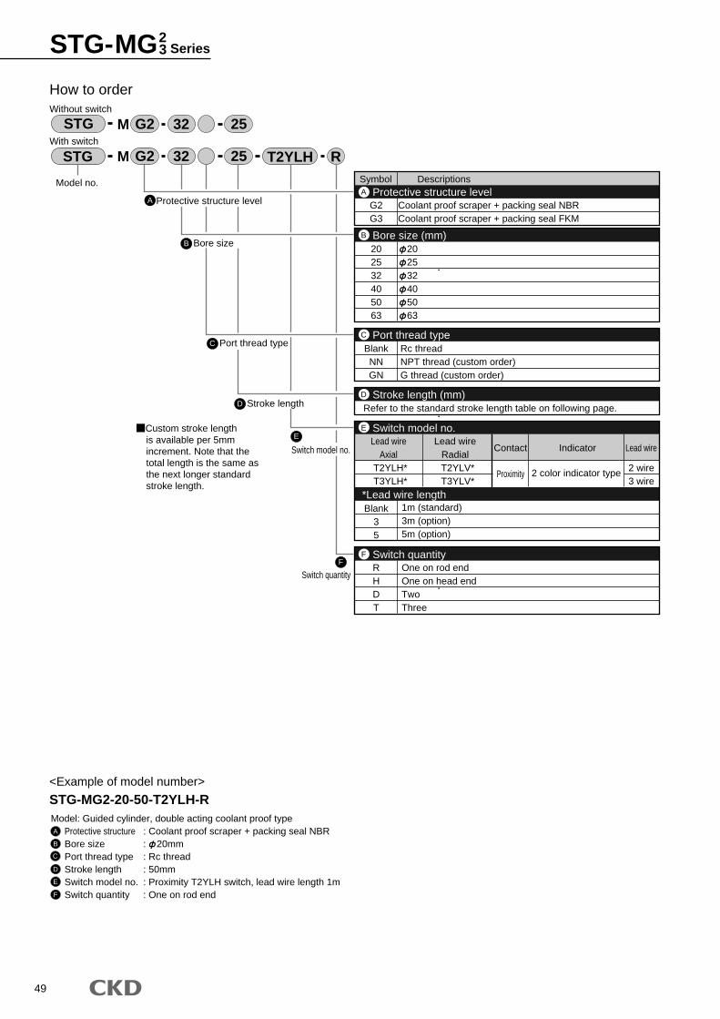
49
STG-MG23 Series
Symbol Descriptions
G2G3
Coolant proof scraper + packing seal NBRCoolant proof scraper + packing seal FKM
202532405063
202532405063
Protective structure levelA
Bore size (mm)B
2 wire3 wire
RHDT
Blank35
One on rod endOne on head endTwoThree
1m (standard)3m (option)5m (option)
Switch quantityF
BlankNNGN
Rc threadNPT thread (custom order)G thread (custom order)
Port thread typeC
Refer to the standard stroke length table on following page.Stroke length (mm)D
T2YLH*T3YLH*
T2YLV*T3YLV*
Lead wireAxial
Lead wireRadial
Contact Indicator Lead wire
Proximity 2 color indicator type
Switch model no.
*Lead wire length
E
A
How to orderWithout switch
With switch
B Bore size
C Port thread type
D Stroke length
E
Switch model no.
Model no.
STG M R32 25 T2YLH
STG M 32 25
G2
G2
Protective structure level
<Example of model number>
STG-MG2-20-50-T2YLH-RModel: Guided cylinder, double acting coolant proof type
Protective structure : Coolant proof scraper + packing seal NBRBore size : 20mmPort thread type : Rc threadStroke length : 50mmSwitch model no. : Proximity T2YLH switch, lead wire length 1mSwitch quantity : One on rod end
A
B
C
D
E
F
F
Switch quantity
Custom stroke lengthis available per 5mm increment. Note that the total length is the same as the next longer standard stroke length.
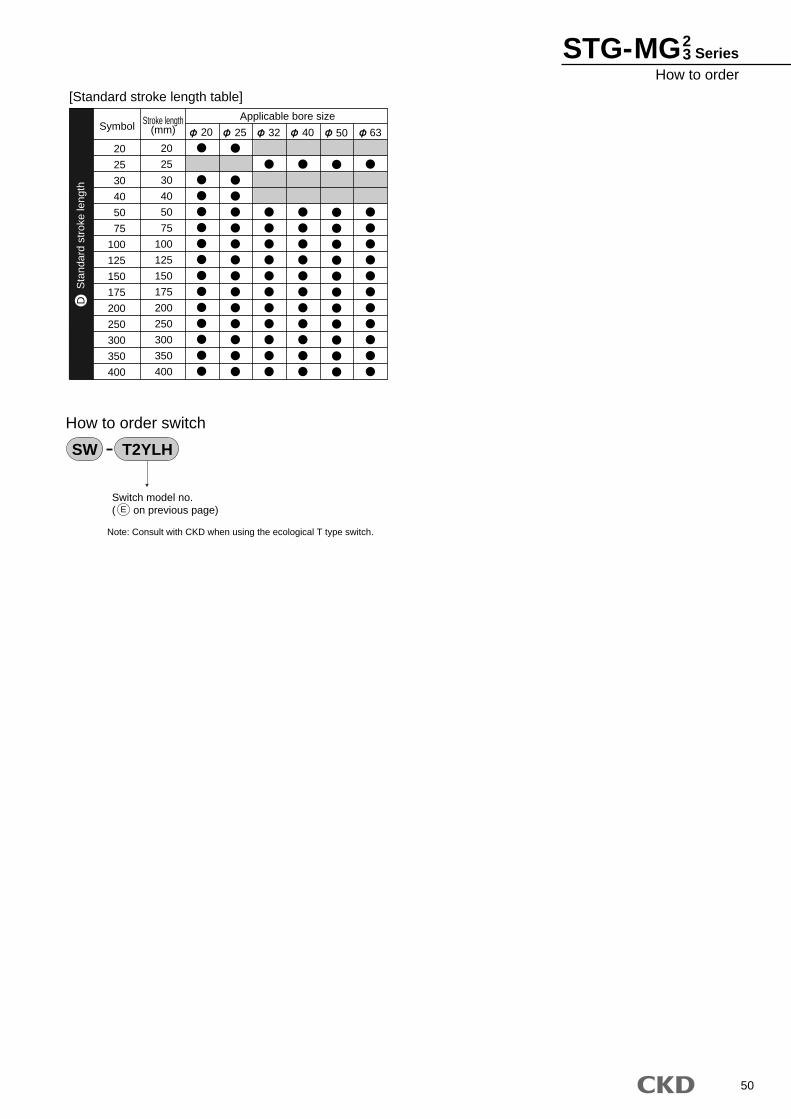
50
20
25
30
40
50
75
100
125
150
175
200
250
300
350
400
SymbolApplicable bore sizeStroke length
(mm)
20
25
30
40
50
75
100
125
150
175
200
250
300
350
400
20 25 32 40 50 63
[Standard stroke length table]
Switch model no.( on previous page)
How to order switch
SW T2YLH
E
Sta
ndar
d st
roke
leng
thD
Note: Consult with CKD when using the ecological T type switch.
STG-MG23 Series
How to order
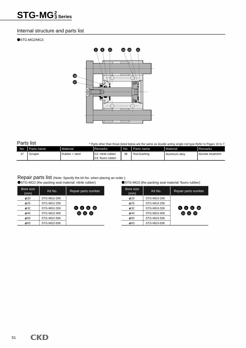
51
STG-MG2/MG3
Internal structure and parts list
Bore size(mm)
Kit No. Repair parts number
Repair parts list (Note: Specify the kit No. when placing an order.)
20
25
32
40
50
63
STG-MG2-20K
STG-MG2-25K
STG-MG2-32K
STG-MG2-40K
STG-MG2-50K
STG-MG2-63K
5 8 11 18
20 21 37
STG-MG2 (the packing seal material: nitrile rubber)
Bore size(mm)
Kit No. Repair parts number
20
25
32
40
50
63
STG-MG3-20K
STG-MG3-25K
STG-MG3-32K
STG-MG3-40K
STG-MG3-50K
STG-MG3-63K
5 8 11 18
20 21 37
STG-MG3 (the packing seal material: fluoro rubber)
Parts name Material Material
G2: nitrile rubberG3: fluoro rubber
Alumite treatmentAluminum alloyRod bushing
No.
3837 Scraper Rubber + steel
Remarks No. Parts name
Material
Remarks
Parts list * Parts other than those listed below are the same as double acting single rod type.Refer to Pages 10 to 7.
11 18 20 215 8
38
37
STG-MG23 Series
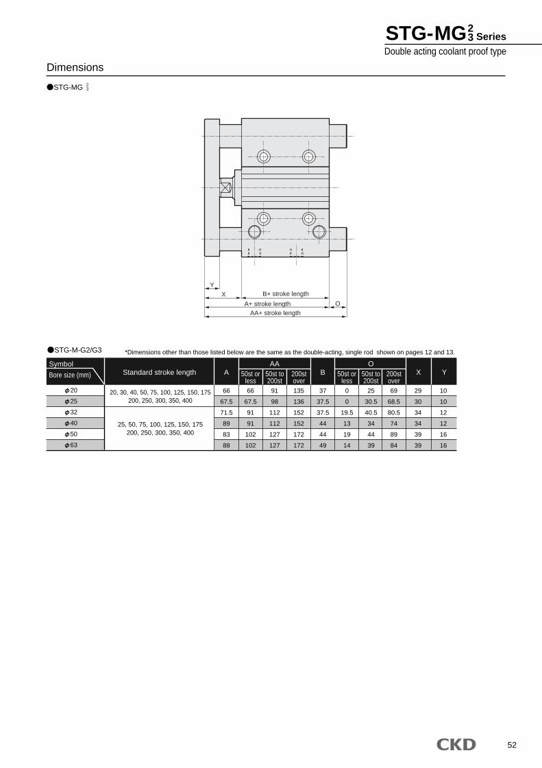
52
STG-MG
Dimensions23
STG-M-G2/G3
20
25
32
40
50
63
Symbol
Bore size (mm)
20, 30, 40, 50, 75, 100, 125, 150, 175200, 250, 300, 350, 400
25, 50, 75, 100, 125, 150, 175200, 250, 300, 350, 400
66
67.5
71.5
89
83
88
66
67.5
91
91
102
102
91
98
112
112
127
127
135
136
152
152
172
172
37
37.5
37.5
44
44
49
0
0
19.5
13
19
14
25
30.5
40.5
34
44
39
69
68.5
80.5
74
89
84
29
30
34
34
39
39
10
10
12
12
16
16
AA50st or
less50st to200st
200stover
OX Y50st or
less50st to200st
200stover
A BStandard stroke length
*Dimensions other than those listed below are the same as the double-acting, single rod shown on pages 12 and 13.
YB+ stroke lengthX
O
AA+ stroke lengthA+ stroke length
STG-MG23 Series
Double acting coolant proof type
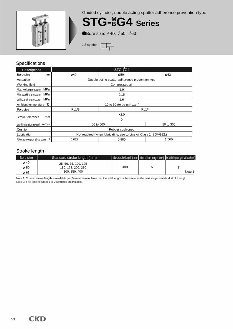
53
Guided cylinder, double acting spatter adherence prevention type
STG-MBG4 Series
Bore size: 40, 50, 63
JIS symbol
Specifications
Bore size
Actuation
Working fluid
Max. working pressure
Min. working pressure
Withstanding pressure
Ambient temperature
Port size
Working piston speed
Cushion
Lubrication
Allowable energy absorption
50
Double acting spatter adherence prevention type
Compressed air
1.0
0.15
1.6
-10 to 60 (to be unfrozen)
+2.0
0
Rubber cushioned
Not required (when lubricating, use turbine oil Class 1 ISOVG32.)
0.9800.627 1.560
Rc1/8 Rc1/4
50 to 500 50 to 300
Descriptions40 63
Stroke length
40
50
63
25, 50, 75, 100, 125150, 175, 200, 250
300, 350, 400400 5
Bore size Standard stroke length (mm) Max. stroke length (mm) Min. stroke length (mm) Min. stroke length of types with switch (mm)
5Note 1
mm
MPa
MPa
MPa
mm/s
J
Stroke tolerance mm
Note 1: Custom stroke length is available per 5mm increment.Note that the total length is the same as the next longer standard stroke length.Note 2: This applies when 1 or 2 switches are installed.
STG- G4MB
54
STG-MBG4 SeriesSpecifications
Cylinder weightSTG-MG4
40
50
63
Descriptions
Bore size (mm)
2.03
3.47
4.31
2.44
4.09
5.05
2.89
4.80
5.87
3.29
5.42
6.60
3.71
6.04
7.33
4.12
6.66
8.07
4.53
7.28
8.80
4.94
7.90
9.53
5.95
9.46
11.32
6.78
10.69
12.77
7.61
11.95
14.23
8.43
13.21
15.68
300 350 400Switch weight
Grommet
0.018
0.018
0.018
75 150125100 17525 50 200 250
Stroke length
Unit: kg
STG-BG4
40
50
63
Descriptions
Bore size (mm)
1.88
3.23
4.07
2.23
3.76
4.71
2.7
4.49
5.56
3.05
5.02
6.2
3.46
5.64
6.93
3.81
6.18
7.57
4.16
6.71
8.22
4.51
7.24
8.86
5.26
8.44
10.25
5.96
9.49
11.61
6.66
10.59
12.87
7.36
11.66
14.13
300 350 400Switch weight
Grommet
0.018
0.018
0.018
75 150125100 17525 50 200 250
Stroke length
Unit: kg
Switch specifications
Applications
Light
Load voltage
Load current
Internal voltage drop
Leakage current
Output delay hour Note 1
(ON delay, OFF delay)
Insulation resistance
Withstand voltage
Maximum shock resistance
Ambient temperature
Protective structure
Note 2
DescriptionsProximity 2 wire
Red/green LED (ON lighting)
24V DC 10%
DC5 to 20mA
6V or less
1.0mA or less
30 to 60ms
100M and over at 500V DC megger
No abnormality when 1000V AC is applied for one minute
980m/s2
-10 to +60
JIS C0920 (water tight type), IEC standards IP67, oil resistance
Lead wire length
Programmable controller
1m (2-conductor oil resistant vinyl cabtire code 0.5mm2) (standard) 1m (2-conductor flame resistant vinyl cabtire cord 0.5mm2) (option)
Note 1: This indicates the time from detection of the piston magnet by the magnetic sensor to switch output.Note 2: Lead wire length is available in 3m and 5m as an option.
T2YD T2YDT
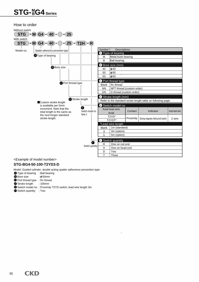
55
STG-MBG4 Series
Symbol Descriptions
MB
Metal bush bearingBall bearing
405063
405063
Type of bearingA
Bore size (mm)B
2 wire
RHDT
Blank35
One on rod endOne on head endTwoThree
1m (standard)3m (option)5m (option)
Switch quantityF
BlankNNGN
Rc threadNPT thread (custom order)G thread (custom order)
Port thread typeC
Refer to the standard stroke length table on following page.Stroke length (mm)D
T2YD*T2YDT*
Axial lead wireAxial
Contact Indicator Axial lead wire
Proximity Strong magnetic field proof switch
Switch model no.
*Lead wire length
E
A
How to orderWithout switch
With switch
B Bore size
C Port thread type
D Stroke length
E
Switch model no.Note 1
Model no.
STG R25 T2H
STG 25
40
40
<Example of model number>
STG-BG4-50-100-T2YD3-DModel: Guided cylinder, double acting spatter adherence prevention type
Type of bearing : Ball bearingBore size : 50mmPort thread type : Rc threadStroke length : 100mmSwitch model no. : Proximity T2YD switch, lead wire length 3mSwitch quantity : Two
A
B
C
D
E
F
F
Switch quantity
Type of bearing
G4M
G4M
Spatter adherence prevention type
Custom stroke lengthis available per 5mm increment. Note that the total length is the same as the next longer standard stroke length.
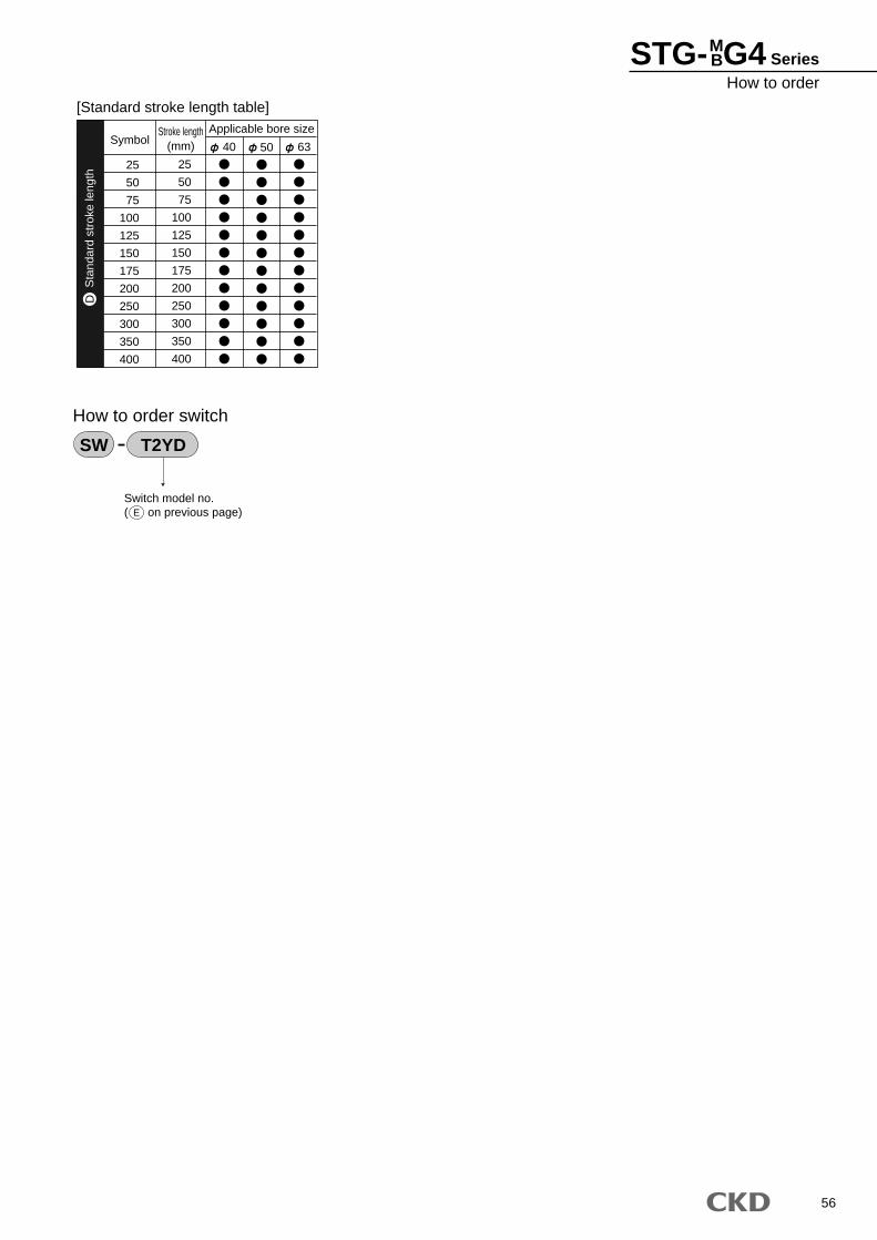
56
STG-MBG4 Series
How to order
25
50
75
100
125
150
175
200
250
300
350
400
SymbolApplicable bore sizeStroke length
(mm)
25
50
75
100
125
150
175
200
250
300
350
400
40 50 63
[Standard stroke length table]
Switch model no.( on previous page)
How to order switch
SW T2YD
E
Sta
ndar
d st
roke
leng
thD

57
Internal structure and parts list
STG-MG4
STG-BG4
Parts name Material Material
Zinc chromate
Alumite
Special rubber
Phosphor bronze
Special rubber
Phosphor bronze
Lube keeping structure
Coil scraper
Lube keeping structure
Coil scraper
No.
43
44
45
46
39
40
41
42
Hexagon socket head cap screw
Lube keeping structure
Coil scraper
Adaptor
Alloy steel
Special rubber
Phosphor bronze
Aluminum alloy
Remarks No. Parts name
Material
Remarks
Parts list * Parts other than those listed below are the same as double acting single rod type.Refer to Pages 10 to 7.
39
40
41
42
43
44
45
46
STG-MBG4 Series
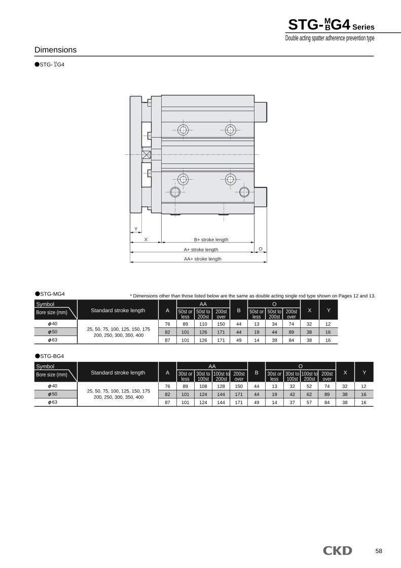
58
STG- G4
DimensionsMB
STG-MG4
40
50
63
Symbol
Bore size (mm)
25, 50, 75, 100, 125, 150, 175200, 250, 300, 350, 400
76
82
87
89
101
101
110
126
126
150
171
171
44
44
49
13
19
14
34
44
39
74
89
84
32
38
38
12
16
16
AA50st or
less50st to200st
200stover
OX Y50st or
less50st to200st
200stover
A BStandard stroke length
STG-BG4
40
50
63
Symbol
Bore size (mm)
25, 50, 75, 100, 125, 150, 175200, 250, 300, 350, 400
76
82
87
89
101
101
108
124
124
128
144
144
150
171
171
44
44
49
13
19
14
32
42
37
52
62
57
74
89
84
32
38
38
12
16
16
AA30st or
less30st to100st
100st to200st
200stover
OX Y30st or
less30st to100st
100st to200st
200stover
A BStandard stroke length
* Dimensions other than those listed below are the same as double acting single rod type shown on Pages 12 and 13.
Y
X B+ stroke length
A+ stroke length O
AA+ stroke length
STG-MBG4 Series
Double acting spatter adherence prevention type
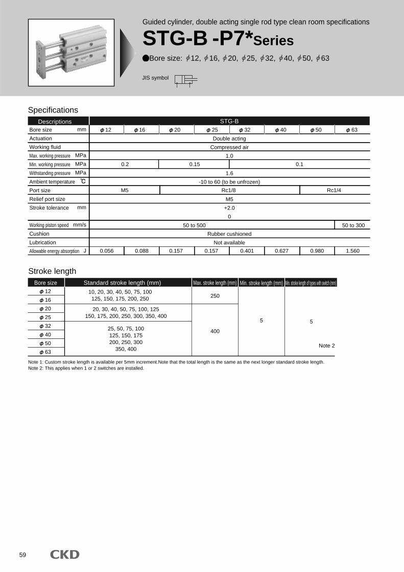
59
Specifications
Bore size
Actuation
Working fluid
Max. working pressure
Min. working pressure
Withstanding pressure
Ambient temperature
Port size
Relief port size
Stroke tolerance
Working piston speed
Cushion
Lubrication
Allowable energy absorption
Double acting
Compressed air
1.0
1.6
-10 to 60 (to be unfrozen)
M5
+2.0
0
Rubber cushioned
Not available
0.2
M5
0.056 0.088 0.157 0.157 0.401 0.627 0.980 1.560
Rc1/8 Rc1/4
50 to 500 50 to 300
0.15 0.1
Descriptions12 16 20 25 32 40 50 63
STG-B
Stroke length
12
16
20
25
32
40
50
63
10, 20, 30, 40, 50, 75, 100125, 150, 175, 200, 250
20, 30, 40, 50, 75, 100, 125150, 175, 200, 250, 300, 350, 400
25, 50, 75, 100125, 150, 175200, 250, 300
350, 400
400
250
5
Bore size Standard stroke length (mm) Max. stroke length (mm) Min. stroke length (mm) Min. stroke length of types with switch (mm)
5
Note 2
mm
MPa
MPa
MPa
mm
mm/s
J
Note 1: Custom stroke length is available per 5mm increment.Note that the total length is the same as the next longer standard stroke length.Note 2: This applies when 1 or 2 switches are installed.
Guided cylinder, double acting single rod type clean room specifications
STG-B -P7*SeriesBore size: 12, 16, 20, 25, 32, 40, 50, 63
JIS symbol
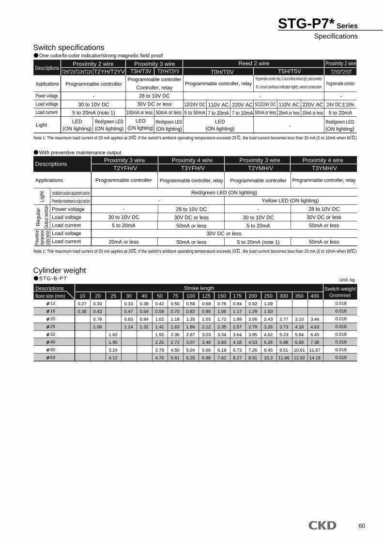
60
Switch specificationsOne color/bi-color indicator/strong magnetic field proof
Cylinder weightSTG-B-P7
Descriptions
Applications
Power voltage
Load voltage
Load current
Light
Reed 2 wire Proximity 2 wire
Programmable controller
-
30 to 10V DC
5 to 20mA (note 1)
12/24V DC
5 to 50mA
110V AC
7 to 20mA
220V AC
7 to 10mA
5/12/24V DC
50mA or less
24V DC 10%
5 to 20mA
110V AC
20mA or less
220V AC
10mA or less
Programmable controller
Controller, relay
28 to 10V DC
30V DC or less
Programmable controller, relay Programmable controllerProgrammable controller, relay, IC circuit (without indicator light), serial connection
IC circuit (without indicator light), serial connection
Proximity 2 wire Proximity 3 wireT2H/T2V/T2JH/T2JV T2YH/T2YV T3H/T3V T3YH/T3YV T0H/T0V T5H/T5V T2YD/T2YDT
- -
-LED
(ON lighting)
LED(ON lighting)
LED(ON lighting)
Red/green LED(ON lighting)
Red/green LED(ON lighting)
Red/green LED(ON lighting)
100mA or less 50mA or less
With preventive maintenance output
Descriptions
Applications Programmable controller
-
30 to 10V DC
5 to 20mA
20mA or less
Programmable controller
-
30 to 10V DC
5 to 20mA
5 to 20mA (note 1)
Programmable controller, relay
28 to 10V DC
30V DC or less
50mA or less
50mA or less
Programmable controller, relay
28 to 10V DC
30V DC or less
50mA or less
50mA or less
T2YFH/V T3YFH/V T2YMH/V T3YMH/V
Red/green LED (ON lighting)
30V DC or less
Yellow LED (ON lighting)-
Note 1: The maximum load current of 20 mA applies at 25 .If the switch's ambient operating temperature exceeds 25 , the load current becomes less than 20 mA.(5 to 10mA when 60 )
Note 1: The maximum load current of 20 mA applies at 25 .If the switch's ambient operating temperature exceeds 25 , the load current becomes less than 20 mA.(5 to 10mA when 60 )
Installation position adjustment section
Preventive maintenance output section
Power voltage
Load voltage
Load current
Load voltage
Load current
Proximity 3 wire Proximity 4 wire Proximity 3 wire Proximity 4 wire
12
16
20
25
32
40
50
63
Descriptions
Bore size (mm)
0.27
0.38
0.30
0.43
0.76
1.06
1.62
1.90
3.24
4.12
0.33
0.47
0.83
1.14
0.38
0.54
0.94
1.32
0.42
0.59
1.02
1.41
1.92
2.25
3.78
4.76
0.50
0.70
1.18
1.63
2.36
2.72
4.50
5.61
0.58
0.82
1.35
1.86
2.67
3.07
5.04
6.25
0.68
0.95
1.55
2.12
3.03
3.48
5.66
6.98
0.76
1.06
1.72
2.35
3.34
3.83
6.19
7.62
0.84
1.17
1.89
2.57
3.64
4.18
6.73
8.27
0.92
1.29
2.06
2.79
3.95
4.53
7.26
8.91
1.09
1.50
2.43
3.28
4.62
5.28
8.45
10.3
2.77
3.73
5.23
5.98
9.51
11.66
3.10
4.18
5.84
6.68
10.61
12.92
3.44
4.63
6.45
7.38
11.67
14.18
10 20 300 350 400Switch weight
Grommet
0.018
0.018
0.018
0.018
0.018
0.018
0.018
0.018
75 150125100 17525 30 40 50 200 250
Stroke length
Unit: kg
Reg
ular
Outp
ut se
ction
Prev
entiv
ema
intenan
ceout
put se
ction
Ligh
t
STG-P7* SeriesSpecifications
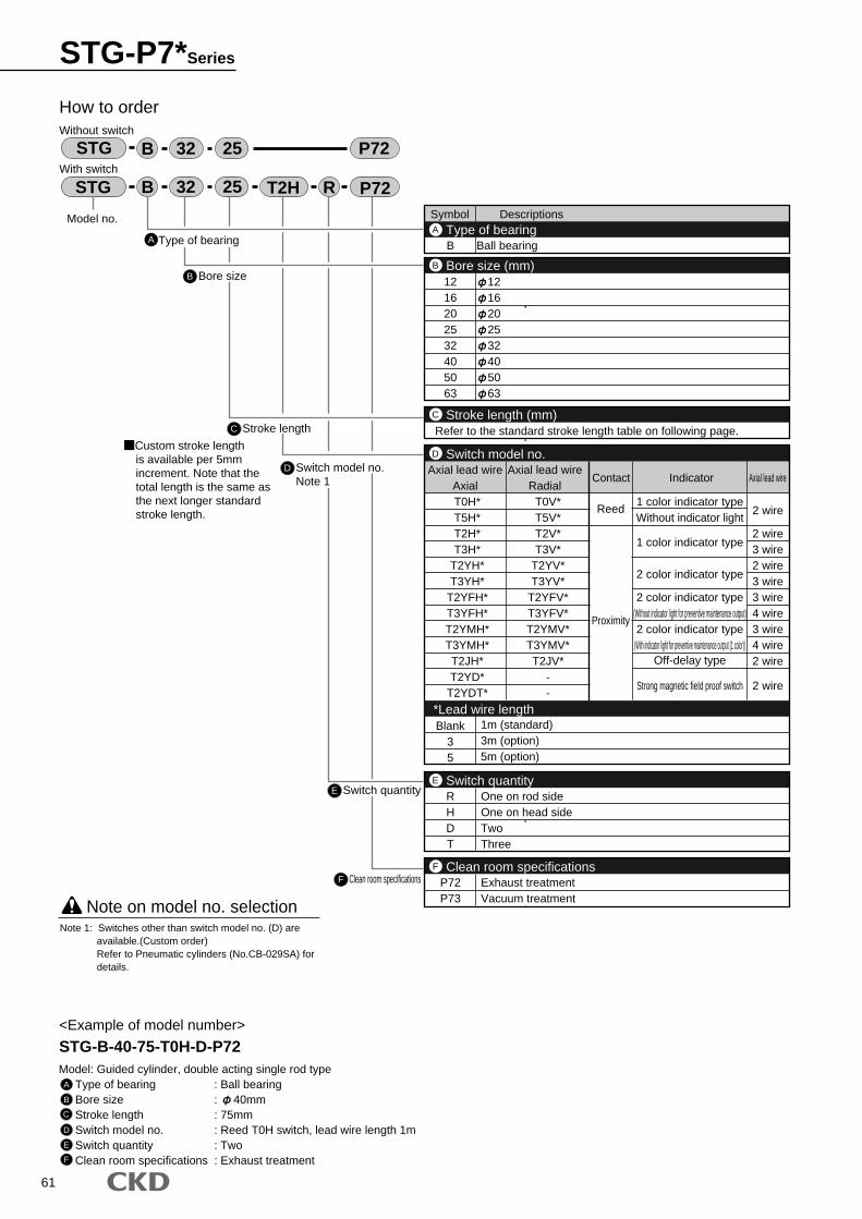
61
Symbol Descriptions
B Ball bearing
1216202532405063
1216202532405063
Type of bearingA
Bore size (mm)B
2 wire
2 wire3 wire2 wire3 wire3 wire4 wire3 wire4 wire2 wire
2 wire
RHDT
One on rod sideOne on head sideTwoThree
Switch quantityE
Refer to the standard stroke length table on following page.Stroke length (mm)C
T0H*T5H*T2H*T3H*
T2YH*T3YH*
T2YFH*T3YFH*T2YMH*T3YMH*T2JH*T2YD*
T2YDT*
T0V*T5V*T2V*T3V*
T2YV*T3YV*
T2YFV*T3YFV*T2YMV*T3YMV*T2JV*
--
Axial lead wireAxial
Axial lead wireRadial
Contact Indicator Axial lead wire
Reed
Proximity
1 color indicator typeWithout indicator light
1 color indicator type
2 color indicator type
2 color indicator type(Without indicator light for preventive maintenance output)2 color indicator type
(With indicator light for preventive maintenance output (1 color))Off-delay type
Strong magnetic field proof switch
Switch model no.D
P72P73
Exhaust treatmentVacuum treatment
Clean room specificationsF
Blank35
1m (standard)3m (option)5m (option)
*Lead wire length
A
How to orderWithout switch
With switch
B Bore size
C Stroke length
D Switch model no.Note 1
Model no.
STG B R32 25 T2H
STG B 32 25
P72
P72
Type of bearing
Custom stroke length
<Example of model number>
STG-B-40-75-T0H-D-P72Model: Guided cylinder, double acting single rod type
Type of bearing : Ball bearingBore size : 40mmStroke length : 75mmSwitch model no. : Reed T0H switch, lead wire length 1mSwitch quantity : TwoClean room specifications : Exhaust treatment
Note on model no. selection
A
B
C
D
E
F
Note 1: Switches other than switch model no. (D) are available.(Custom order)Refer to Pneumatic cylinders (No.CB-029SA) for details.
is available per 5mm increment. Note that the total length is the same as the next longer standard stroke length.
E Switch quantity
F Clean room specifications
STG-P7*Series
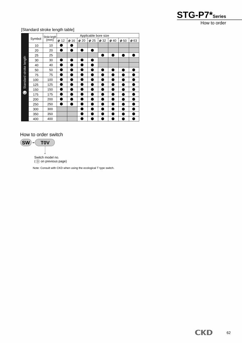
62
10
20
25
30
40
50
75
100
125
150
175
200
250
300
350
400
SymbolApplicable bore sizeStroke length
(mm)
10
20
25
30
40
50
75
100
125
150
175
200
250
300
350
400
12 16 20 25 32 40 50 63
[Standard stroke length table]
Switch model no.( on previous page)
How to order switch
SW T0V
D
Sta
ndar
d st
roke
leng
thC
Note: Consult with CKD when using the ecological T type switch.
STG-P7*SeriesHow to order
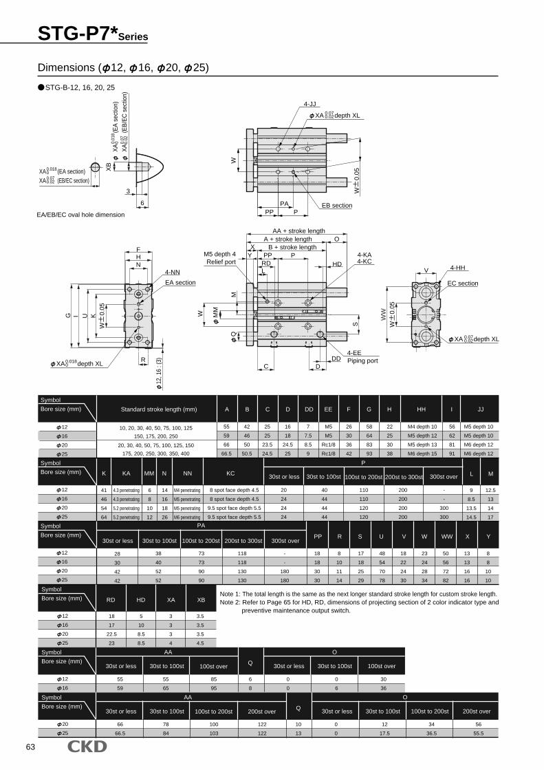
63
12
16
20
25
Symbol
Bore size (mm) Standard stroke length (mm) A
K KA MM N NN KC
B C D DD EE F G H HH I JJ
ML
PP R S U V W WW X Y
P
PA
STG-B-12, 16, 20, 25
Dimensions ( 12, 16, 20, 25)
18
17
22.5
23
5
10
8.5
8.5
3
3
3
4
3.5
3.5
3.5
4.5
12
16
20
25
Symbol
Bore size (mm)
12
16
20
25
Symbol
Bore size (mm)
12
16
20
25
Symbol
Bore size (mm)
55
59
55
65
85
95
6
8
12
16
Symbol
Bore size (mm)
0
0
0
6
30
36
30st or less
30st to 100st 100st to 200st 200st to 300st 300st over
30st to 100st 100st to 200st 200st to 300st
30st or less
300st over
66
66.5
78
84
100
103
10
13
122
122
20
25
Symbol
Bore size (mm)
0
0
12
17.5
34
36.5
56
55.5
Q100st to 200st 200st over30st or less 30st to 100st
AA
30st or less 30st to 100st 100st to 200st 200st over
O
RD HD XA XB
Q100st over30st or less 30st to 100st
AA
30st or less 30st to 100st 100st over
O
55
59
66
66.5
41
46
54
64
6
8
10
12
14
16
18
26
4.3 penetrating
4.3 penetrating
5.2 penetrating
5.2 penetrating
M4 penetrating
M5 penetrating
M5 penetrating
M6 penetrating
42
46
50
50.5
25
25
23.5
24.5
16
18
24.5
25
7
7.5
8.5
9
M5
M5
Rc1/8
Rc1/8
26
30
36
42
58
64
83
93
22
25
30
38
M4 depth 10
M5 depth 12
M5 depth 13
M6 depth 15
56
62
81
91
9
8.5
13.5
14.5
12.5
13
14
17
M5 depth 10
M5 depth 10
M6 depth 12
M6 depth 12
20
24
24
24
8 spot face depth 4.5
8 spot face depth 4.5
9.5 spot face depth 5.5
9.5 spot face depth 5.5
38
40
52
52
73
73
90
90
118
118
130
130
-
-
180
180
18
18
30
30
8
10
11
14
17
18
25
29
48
54
70
78
18
22
24
30
23
24
28
34
50
56
72
82
13
13
16
16
8
8
10
10
40
44
44
44
110
110
120
120
-
-
300
300
200
200
200
200
28
30
42
42
10, 20, 30, 40, 50, 75, 100, 125
150, 175, 200, 250
20, 30, 40, 50, 75, 100, 125, 150
175, 200, 250, 300, 350, 400
T0H*
CKD
CKD
T0H*
V
6
3
XB
W
0.0
5
PPA
PP
12, 1
6 : (
3)R
F
I KW
0
.05
Q
MM
PP PYX
S
RD
XA (EA section)XA (EB/EC section)
0.01800.070.02
EA/EB/EC oval hole dimension
XA
(EA
sec
tion)
XA
(EB
/EC
sec
tion)
0.01
80 0.
070.
02
W
W
0.0
5
XA depth XL0.070.02
4-JJ
EB section
HN
UG
XA depth XL0.0180
4-NN
EA section
W
MO
4-EEPiping port
4-KA4-KC
AA + stroke lengthA + stroke length
B + stroke length
DDD
C
M5 depth 4Relief port
WW
XA depth XL0.070.02
4-HH
EC section
HDL
Note 1: The total length is the same as the next longer standard stroke length for custom stroke length.Note 2: Refer to Page 65 for HD, RD, dimensions of projecting section of 2 color indicator type and
preventive maintenance output switch.
STG-P7*Series
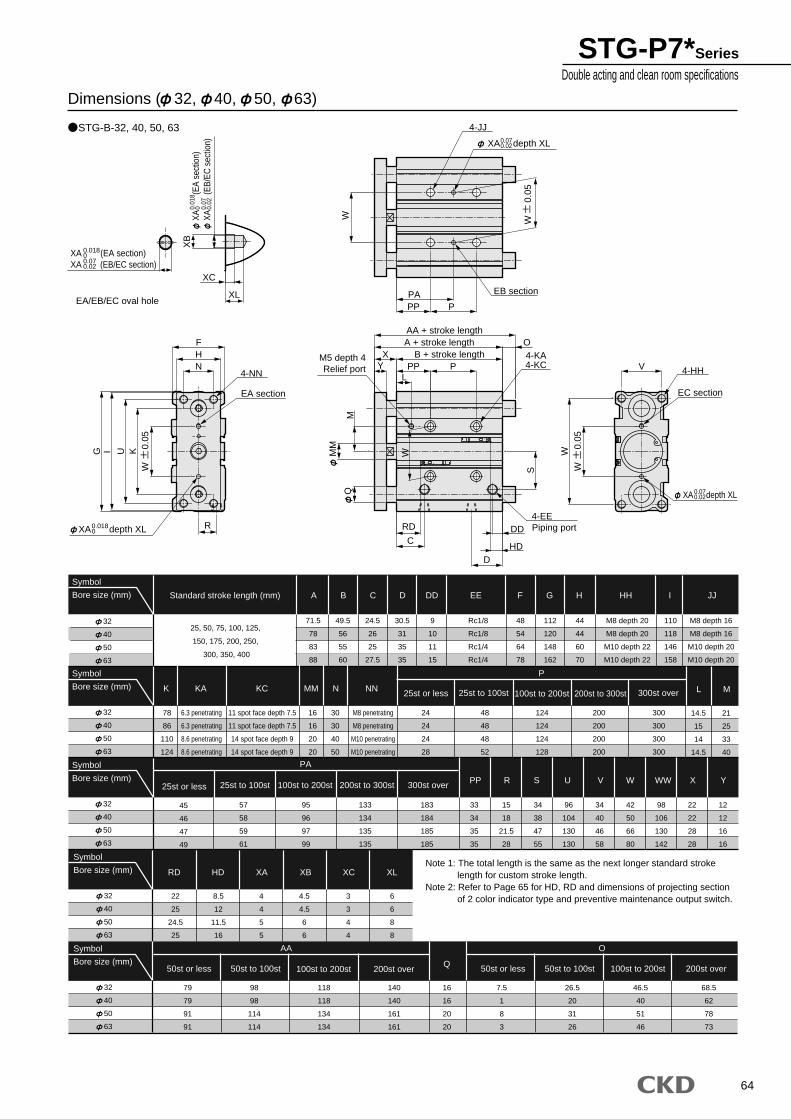
64
32
40
50
63
Symbol
Bore size (mm) Standard stroke length (mm) A
K KA KC MM N NN
B C D DD EE F G H HH I JJ
ML
PP R S U V W WW X Y
P
PA
STG-B-32, 40, 50, 63
Dimensions ( 32, 40, 50, 63)
22
25
24.5
25
8.5
12
11.5
16
4
4
5
5
4.5
4.5
6
6
3
3
4
4
6
6
8
8
32
40
50
63
Symbol
Bore size (mm)
32
40
50
63
Symbol
Bore size (mm)
32
40
50
63
Symbol
Bore size (mm)
25st or less
25st to 100st 100st to 200st 200st to 300st 300st over
25st to 100st 100st to 200st 200st to 300st
25st or less
300st over
79
79
91
91
98
98
114
114
118
118
134
134
16
16
20
20
140
140
161
161
32
40
50
63
Symbol
Bore size (mm)
7.5
1
8
3
26.5
20
31
26
46.5
40
51
46
68.5
62
78
73
Q100st to 200st 200st over50st or less 50st to 100st
AA
50st or less 50st to 100st 100st to 200st 200st over
O
RD HD XA XB XC XL
71.5
78
83
88
49.5
56
55
60
24.5
26
25
27.5
30.5
31
35
35
9
10
11
15
Rc1/8
Rc1/8
Rc1/4
Rc1/4
48
54
64
78
112
120
148
162
44
44
60
70
M8 depth 20
M8 depth 20
M10 depth 22
M10 depth 22
110
118
146
158
14.5
15
14
14.5
21
25
33
40
M8 depth 16
M8 depth 16
M10 depth 20
M10 depth 20
24
24
24
28
78
86
110
124
16
16
20
20
30
30
40
50
6.3 penetrating
6.3 penetrating
8.6 penetrating
8.6 penetrating
M8 penetrating
M8 penetrating
M10 penetrating
M10 penetrating
11 spot face depth 7.5
11 spot face depth 7.5
14 spot face depth 9
14 spot face depth 9
57
58
59
61
95
96
97
99
133
134
135
135
183
184
185
185
33
34
35
35
15
18
21.5
28
34
38
47
55
96
104
130
130
34
40
46
58
42
50
66
80
98
106
130
142
22
22
28
28
12
12
16
16
48
48
48
52
124
124
124
128
300
300
300
300
200
200
200
200
45
46
47
49
25, 50, 75, 100, 125,
150, 175, 200, 250,
300, 350, 400
T0H*
CKD
CKD
T0H
EA/EB/EC oval hole PP P
W
0.0
5
UI
W
0.0
5
R
G
NHF
CDD
4-EEPiping port
4-KA4-KC
D
PP PYX B + stroke length
A + stroke length OAA + stroke length
MM
Q
SRD
HD
V
WW
0
.05
K
XC
XL
L
PA
XB
W
XA (EA section)XA (EB/EC section)
0.01800.070.02
XA
(E
A se
ctio
n)XA
(EB/
EC s
ectio
n)
0.01
80 0.
070.
02
W
XA depth XL0.070.02
4-JJ
EB section
4-NN
EA section
XA depth XL0.0180
MM5 depth 4Relief port
XA depth XL0.070.02
4-HH
EC section
Note 1: The total length is the same as the next longer standard stroke length for custom stroke length.
Note 2: Refer to Page 65 for HD, RD and dimensions of projecting section of 2 color indicator type and preventive maintenance output switch.
STG-P7*SeriesDouble acting and clean room specifications
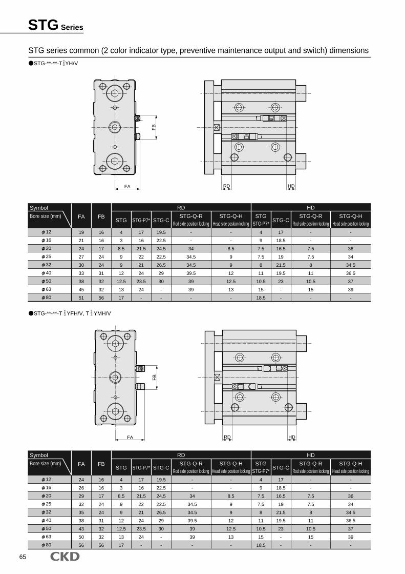
65
12
16
20
25
32
40
50
63
80
Symbol
Bore size (mm)
19
21
24
27
30
33
38
45
51
16
16
17
24
24
31
32
32
56
4
3
8.5
9
9
12
12.5
13
17
17
16
21.5
22
21
24
23.5
24
-
19.5
22.5
24.5
22.5
26.5
29
30
-
-
-
-
34
34.5
34.5
39.5
39
39
-
-
-
8.5
9
9
12
12.5
13
-
4
9
7.5
7.5
8
11
10.5
15
18.5
17
18.5
16.5
19
21.5
19.5
23
-
-
-
-
7.5
7.5
8
11
10.5
15
-
-
-
36
34
34.5
36.5
37
39
-
STG-Q-RRod side position locking
STG-Q-HHead side position locking
STG-Q-RRod side position locking
STG-Q-HHead side position locking
STGSTG-P7*
RD HD
STG STG-C STG-CSTG-P7*FBFA
12
16
20
25
32
40
50
63
80
Symbol
Bore size (mm)
24
26
29
32
35
38
43
50
56
16
16
17
24
24
31
32
32
56
4
3
8.5
9
9
12
12.5
13
17
17
16
21.5
22
21
24
23.5
24
-
19.5
22.5
24.5
22.5
26.5
29
30
-
-
-
-
34
34.5
34.5
39.5
39
39
-
-
-
8.5
9
9
12
12.5
13
-
4
9
7.5
7.5
8
11
10.5
15
18.5
17
18.5
16.5
19
21.5
19.5
23
-
-
-
-
7.5
7.5
8
11
10.5
15
-
-
-
36
34
34.5
36.5
37
39
-
STG-Q-RRod side position locking
STG-Q-HHead side position locking
STG-Q-RRod side position locking
STG-Q-HHead side position locking
STGSTG-P7*
RD HD
STG STG-C STG-CSTG-P7*FBFA
STG series common (2 color indicator type, preventive maintenance output and switch) dimensions
STG-**-**-T YH/V23
STG-**-**-T YFH/V, T YMH/V23
23
HDRD
FB
FA
FB
FA HDRD
STG Series
66
M E M OM E M O
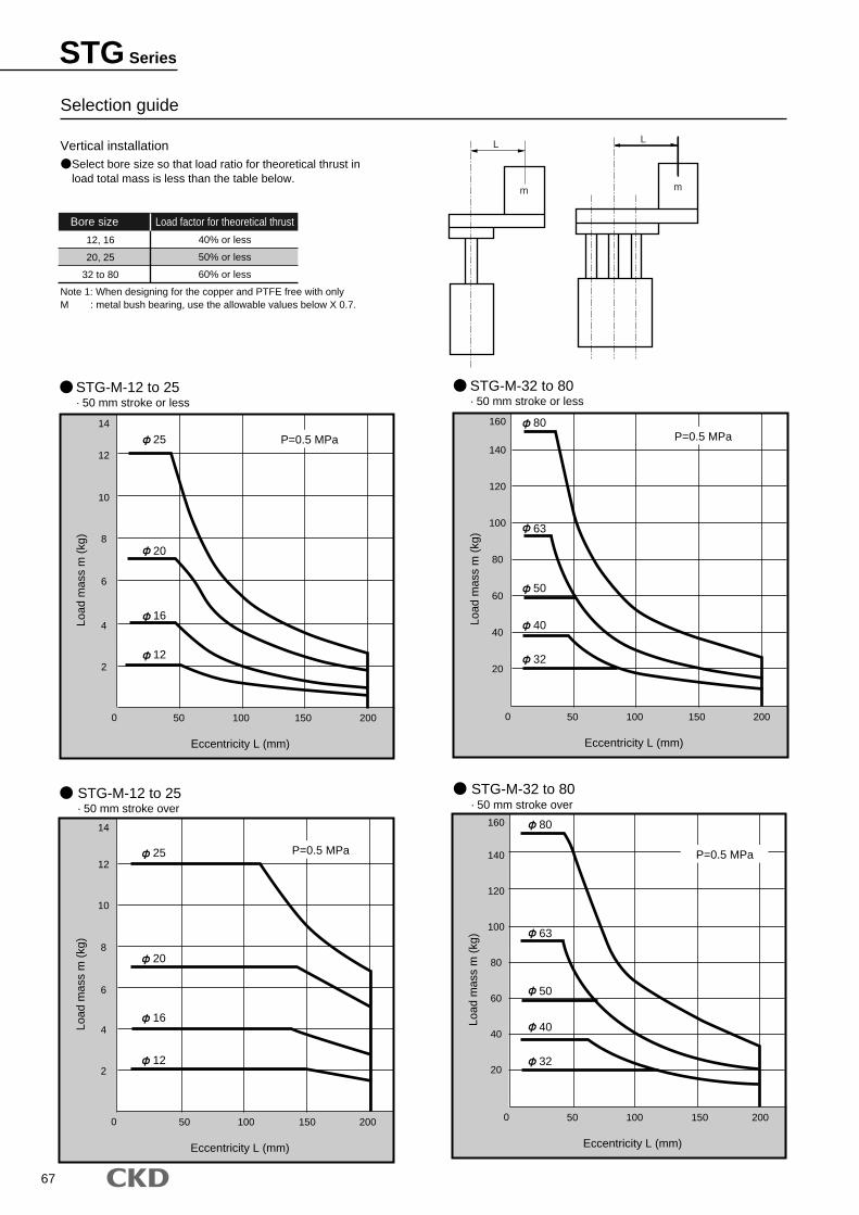
67
Selection guide
Vertical installationSelect bore size so that load ratio for theoretical thrust inload total mass is less than the table below.
Note 1: When designing for the copper and PTFE free with onlyM : metal bush bearing, use the allowable values below X 0.7.
12, 16
20, 25
32 to 80
Bore size
40% or less
50% or less
60% or less
Load factor for theoretical thrust
· 50 mm stroke over
STG-M-12 to 25· 50 mm stroke or less
STG-M-12 to 25
STG-M-32 to 80· 50 mm stroke or less
STG-M-32 to 80· 50 mm stroke over
L
m
L
m
50 100 150 200
2
4
6
8
10
12
14
Load
mas
s m
(kg
)
Eccentricity L (mm)
0
12
16
20
25 P=0.5 MPa
50 100 150 200
20
40
60
80
100
120
140
160
Load
mas
s m
(kg
)
Eccentricity L (mm)
0
63
80
50
40
32
P=0.5 MPa
50 100 150 200
2
4
6
8
10
12
14
Load
mas
s m
(kg
)
Eccentricity L (mm)
0
12
16
20
25 P=0.5 MPa
50 100 150 200
20
40
60
80
100
120
140
160
Load
mas
s m
(kg
)
Eccentricity L (mm)
0
32
40
50
63
80P=0.5 MPa
STG Series
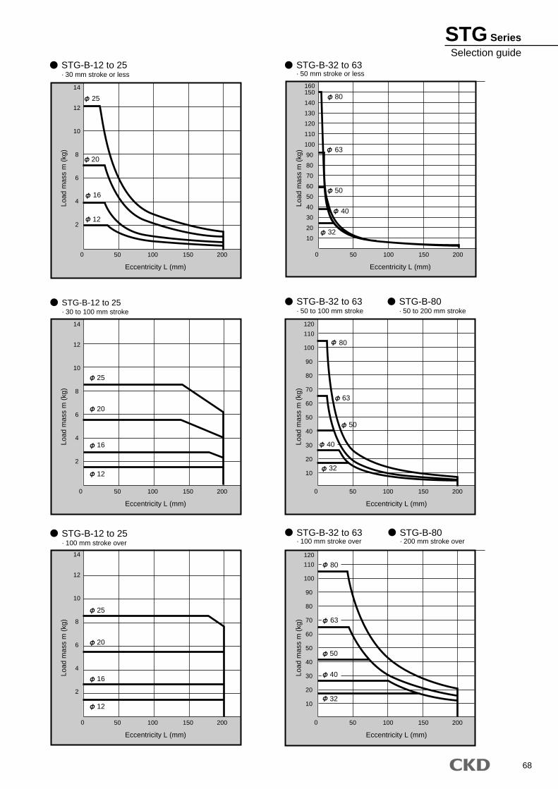
68
STG-B-32 to 63· 50 mm stroke or less
STG-B-12 to 25· 30 mm stroke or less
STG-B-12 to 25· 30 to 100 mm stroke
STG-B-32 to 63· 50 to 100 mm stroke
STG-B-80· 50 to 200 mm stroke
STG-B-12 to 25· 100 mm stroke over
STG-B-32 to 63· 100 mm stroke over
STG-B-80· 200 mm stroke over
50 100 150 200
2
4
6
8
10
12
14
2
4
6
8
10
12
14
2
4
6
8
10
12
14
10
20
30
40
50
60
70
80
90
100
110
120
130
140
150160
Load
mas
s m
(kg
)
Load
mas
s m
(kg
)
Eccentricity L (mm) Eccentricity L (mm)
0
50 100 150 200
10
20
30
40
50
60
70
80
90
100
110
120
10
20
30
40
50
60
70
80
90
100
110
120
Load
mas
s m
(kg
)
Load
mas
s m
(kg
)
Eccentricity L (mm) Eccentricity L (mm)
0 50 100 150 2000
50 100 150 2000
12
16
20
25
25
20
16
12
25
20
16
12
63
80
50
40
32
63
80
50
32
50 100 150 200
Load
mas
s m
(kg
)
Load
mas
s m
(kg
)
Eccentricity L (mm) Eccentricity L (mm)
0 50 100 150 2000
50
32
40
63
80
40
STG SeriesSelection guide
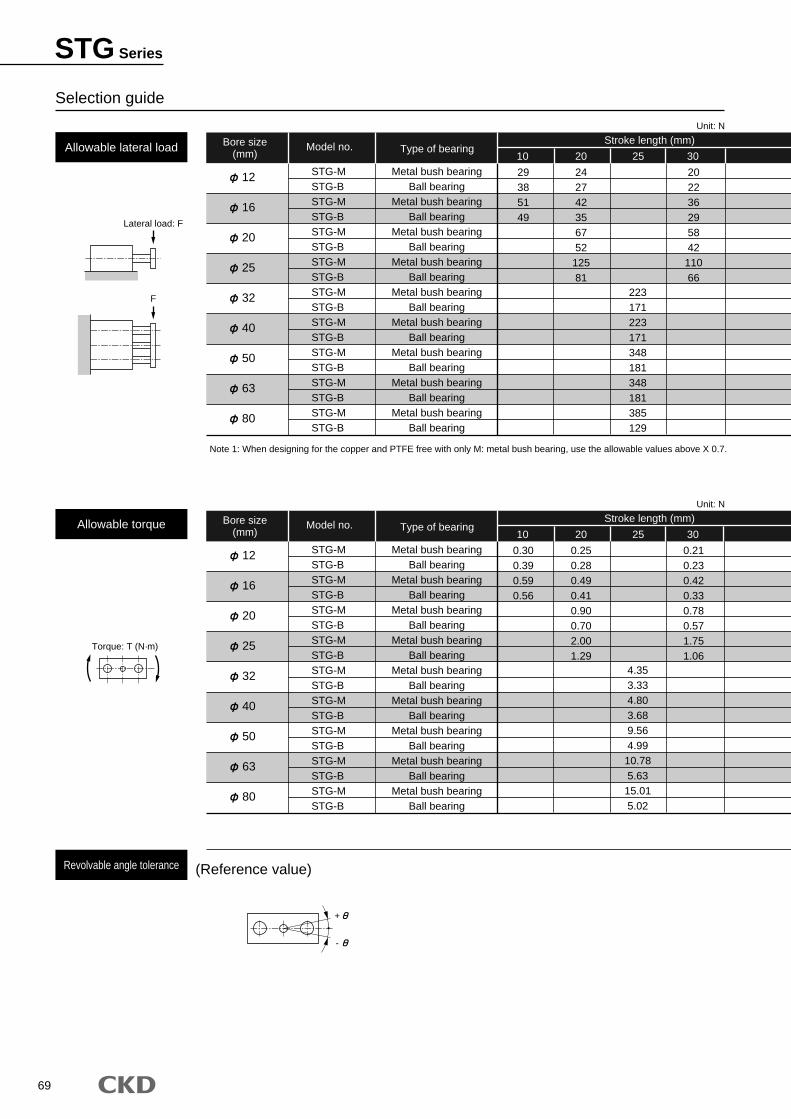
69
Bore size(mm)
Model no. Type of bearing10 20 25 30
12
16
20
25
32
40
50
63
80
STG-MSTG-BSTG-MSTG-BSTG-MSTG-BSTG-MSTG-BSTG-MSTG-BSTG-MSTG-BSTG-MSTG-BSTG-MSTG-BSTG-MSTG-B
Metal bush bearingBall bearing
Metal bush bearingBall bearing
Metal bush bearingBall bearing
Metal bush bearingBall bearing
Metal bush bearingBall bearing
Metal bush bearingBall bearing
Metal bush bearingBall bearing
Metal bush bearingBall bearing
Metal bush bearingBall bearing
29385149
24274235675212581
223171223171348181348181385129
20223629584211066
Allowable lateral load
Unit: N
Allowable torque
Revolvable angle tolerance
Stroke length (mm)
Lateral load: F
F
Torque: T (N·m)
+
-
Bore size(mm)
Model no. Type of bearing10 20 25 30
12
16
20
25
32
40
50
63
80
STG-MSTG-BSTG-MSTG-BSTG-MSTG-BSTG-MSTG-BSTG-MSTG-BSTG-MSTG-BSTG-MSTG-BSTG-MSTG-BSTG-MSTG-B
Metal bush bearingBall bearing
Metal bush bearingBall bearing
Metal bush bearingBall bearing
Metal bush bearingBall bearing
Metal bush bearingBall bearing
Metal bush bearingBall bearing
Metal bush bearingBall bearing
Metal bush bearingBall bearing
Metal bush bearingBall bearing
0.300.390.590.56
0.250.280.490.410.900.702.001.29
4.353.334.803.689.564.9910.785.6315.015.02
0.210.230.420.330.780.571.751.06
Unit: N
Stroke length (mm)
(Reference value)
Selection guide
Note 1: When designing for the copper and PTFE free with only M: metal bush bearing, use the allowable values above X 0.7.
STG Series
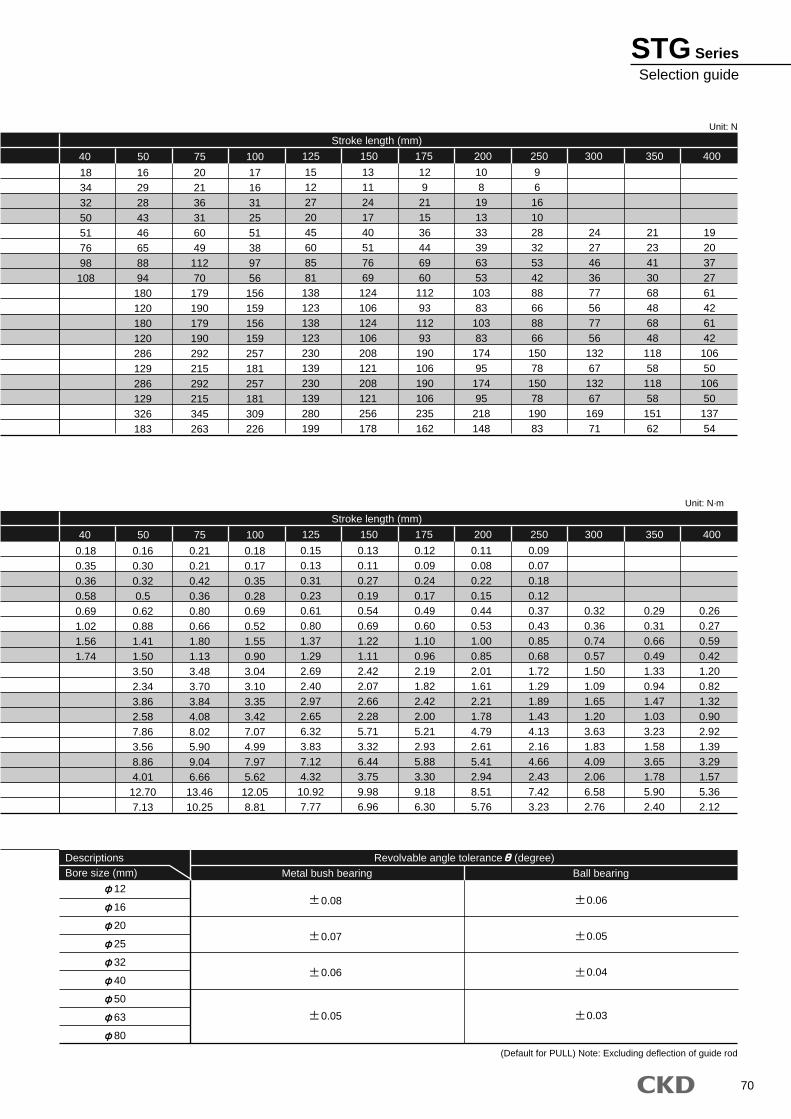
70
Stroke length (mm)
1512272045608581
138123138123230139230139280199
1311241740517669124106124106208121208121256178
1292115364469601129311293190106190106235162
125
10819133339635310383103831749517495218148
150
9616102832534288668866150781507819083
175
2427463677567756132671326716971
200
2123413068486848118581185815162
250
1920372761426142
10650
10650
13754
300 350 400
Unit: N
Unit: N·m
DescriptionsBore size (mm)
Revolvable angle tolerance (degree)
Metal bush bearing
0.08
0.07
0.06
0.05
0.06
0.05
0.04
0.03
Ball bearing
12
16
20
25
32
40
50
63
80
(Default for PULL) Note: Excluding deflection of guide rod
40 50 75 100
18343250517698108
1629284346658894180120180120286129286129326183
202136316049
11270
179190179190292215292215345263
1716312551389756
156159156159257181257181309226
Stroke length (mm)
0.150.130.310.230.610.801.371.292.692.402.972.656.323.837.124.32
10.927.77
0.130.110.270.190.540.691.221.112.422.072.662.285.713.326.443.759.986.96
0.120.090.240.170.490.601.100.962.191.822.422.005.212.935.883.309.186.30
125
0.110.080.220.150.440.531.000.852.011.612.211.784.792.615.412.948.515.76
150
0.090.070.180.120.370.430.850.681.721.291.891.434.132.164.662.437.423.23
175
0.320.360.740.571.501.091.651.203.631.834.092.066.582.76
200
0.290.310.660.491.330.941.471.033.231.583.651.785.902.40
250
0.260.270.590.421.200.821.320.902.921.393.291.575.362.12
300 350 40040 50 75 100
0.180.350.360.580.691.021.561.74
0.160.300.320.50.620.881.411.503.502.343.862.587.863.568.864.0112.707.13
0.210.210.420.360.800.661.801.133.483.703.844.088.025.909.046.66
13.4610.25
0.180.170.350.280.690.521.550.903.043.103.353.427.074.997.975.62
12.058.81
STG SeriesSelection guide
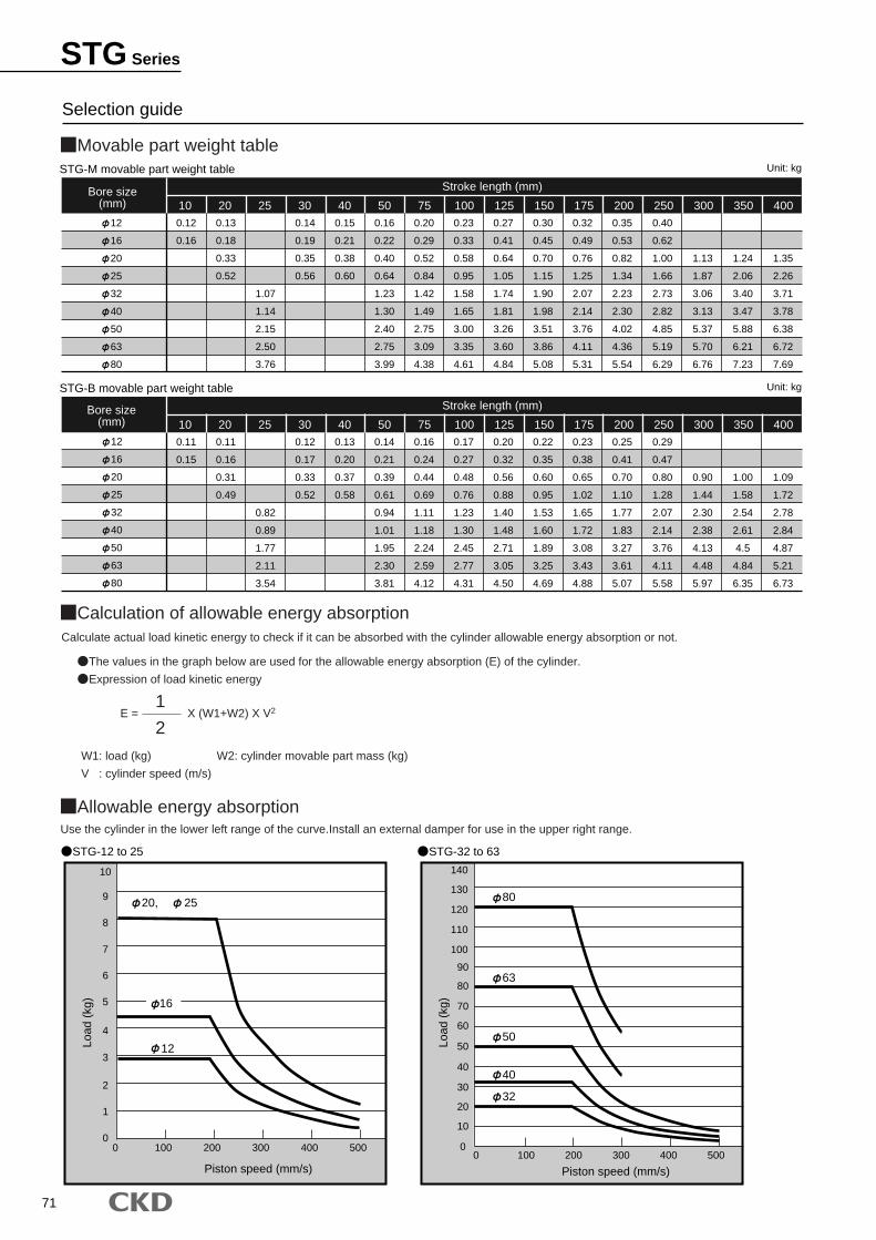
71
12
16
20
25
32
40
50
63
80
Bore size(mm)
Stroke length (mm)
0.12
0.16
0.13
0.18
0.33
0.52
1.07
1.14
2.15
2.50
3.76
0.14
0.19
0.35
0.56
0.15
0.21
0.38
0.60
0.16
0.22
0.40
0.64
1.23
1.30
2.40
2.75
3.99
0.20
0.29
0.52
0.84
1.42
1.49
2.75
3.09
4.38
0.23
0.33
0.58
0.95
1.58
1.65
3.00
3.35
4.61
0.27
0.41
0.64
1.05
1.74
1.81
3.26
3.60
4.84
0.30
0.45
0.70
1.15
1.90
1.98
3.51
3.86
5.08
0.32
0.49
0.76
1.25
2.07
2.14
3.76
4.11
5.31
0.35
0.53
0.82
1.34
2.23
2.30
4.02
4.36
5.54
0.40
0.62
1.00
1.66
2.73
2.82
4.85
5.19
6.29
1.13
1.87
3.06
3.13
5.37
5.70
6.76
1.24
2.06
3.40
3.47
5.88
6.21
7.23
1.35
2.26
3.71
3.78
6.38
6.72
7.69
10 20 25 30 40 50 75 100 125 150 175 200 250 300 350 400
Movable part weight table
Calculation of allowable energy absorption
Allowable energy absorption
STG-M movable part weight table
12
16
20
25
32
40
50
63
80
Bore size(mm)
Stroke length (mm)
0.11
0.15
0.11
0.16
0.31
0.49
0.82
0.89
1.77
2.11
3.54
0.12
0.17
0.33
0.52
0.13
0.20
0.37
0.58
0.14
0.21
0.39
0.61
0.94
1.01
1.95
2.30
3.81
0.16
0.24
0.44
0.69
1.11
1.18
2.24
2.59
4.12
0.17
0.27
0.48
0.76
1.23
1.30
2.45
2.77
4.31
0.20
0.32
0.56
0.88
1.40
1.48
2.71
3.05
4.50
0.22
0.35
0.60
0.95
1.53
1.60
1.89
3.25
4.69
0.23
0.38
0.65
1.02
1.65
1.72
3.08
3.43
4.88
0.25
0.41
0.70
1.10
1.77
1.83
3.27
3.61
5.07
0.29
0.47
0.80
1.28
2.07
2.14
3.76
4.11
5.58
0.90
1.44
2.30
2.38
4.13
4.48
5.97
1.00
1.58
2.54
2.61
4.5
4.84
6.35
1.09
1.72
2.78
2.84
4.87
5.21
6.73
10 20 25 30 40 50 75 100 125 150 175 200 250 300 350 400
STG-B movable part weight table
W1: load (kg) W2: cylinder movable part mass (kg)
V : cylinder speed (m/s)
Calculate actual load kinetic energy to check if it can be absorbed with the cylinder allowable energy absorption or not.
Use the cylinder in the lower left range of the curve.Install an external damper for use in the upper right range.
The values in the graph below are used for the allowable energy absorption (E) of the cylinder.
Expression of load kinetic energy
E = X (W1+W2) X V2
2
1
Unit: kg
Unit: kg
0 100 300200 400 5000
1
2
3
4
5
6
7
8
9
10
Load
(kg
)
Piston speed (mm/s)
20, 25
12
0 100 200 300 400 5000
10
20
30
40
50
60
70
80
90
100
110
120
130
140
Load
(kg
)
Piston speed (mm/s)
63
80
40
32
50
16
Selection guide
STG-12 to 25 STG-32 to 63
STG Series
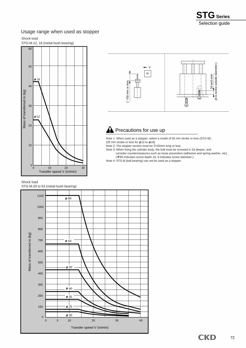
72
Usage range when used as stopperShock loadSTG-M-12, 16 (metal bush bearing)
Shock loadSTG-M-20 to 63 (metal bush bearing)
Note 1: When used as a stopper, select a model of 50 mm stroke or less (STG-M) .(30 mm stroke or less for 12 to 16)Note 2: The stopper section must be =50mm long or less.Note 3: When fixing the cylinder body, the bolt must be screwed in 2d deeper, and consider countermeasures such as loose prevention (adhesive and spring washer, etc) . ( 80 indicates screw depth 1d. d indicates screw diameter.)Note 4: STG-B (ball bearing) can not be used as a stopper.
00
10
20
12
16
30
40
50
60
10 20 30Transfer speed V (m/min)
Mas
s of
tran
sfer
red
m (
kg)
V
m
2d a
nd o
ver
(d is
scr
ew o
utsi
de d
iam
eter
.)
00
100
200
300
400
500
600
700
800
900
1000
1100
5 10 20 30 40
Transfer speed V (m/min)
Mas
s of
tran
sfer
red
m (
kg)
63
80
50
40
32
25
20
=50
mm
or
less
Precautions for use up
STG SeriesSelection guide
2006.6.ACC
CKD CORPORATION TAIWAN BRANCH
M-CKD PRECISION SDN.BHD.CKD USA CORPORATION
CKD UK REPRESENTATIVE
CKD CORPORATION EUROPE BRANCH
CKD BELGIUM REPRESENTATIVE
CKD CO.,LTD.,o.s. CZECH OFFICE
CKD KOREA CORPORATION
CKD THAI CORPORATION LTD.
CKD SINGAPORE PTE. LTD.
●WUXI OFFICE ●NANJING OFFICE ●HANGZHOU OFFICE ●WUHAN OFFICE ●QINGDAO OFFICE
●SUZHOU OFFICE ●BEJING OFFICE ●TIANJING OFFICE ●CHANG CHUN OFFICE ●DALIAN OFFICE
●SHENYANG OFFICE ●XIAN OFFICE ●CHONGQING OFFICE ●CHENGDU OFFICE ●GUANGZHOU OFFICE ●SHENZHEN OFFICE
●CINCINNATI OFFICE ●AUSTIN OFFICE ●SAN JOSE OFFICE
●JOHOR BAHRU OFFICE ●MELAKA OFFICE ●PENANG OFFICE
●LAEMCHABANG OFFICE ●NAVANAKORN OFFICE ●RAYONG OFFICE ●LAMPHUN OFFICE ●KORAT OFFICE ●AMATANAKORN OFFICE
CKD(SHANGHAI) CORPORATION
□ OVERSEAS DPT. SALES DIV. 2-250 Ouji Komaki, Aichi 485-8551, Japan □ PHONE +81-(0)568-74-1336 FAX +81-(0)568-77-3412
Home Page Address http://www.ckd.co.jp/
U.S.A CKD USA CORPORATION ● HEADQUARTERS 4080 Winnetka Avenue, Rolling Meadows, IL 60008 USA PHONE +1-847-368-0539 FAX +1-847-788-0575
EUROPE CKD EUROPE BRANCH De Fruittuinen 28 Hoofddorp 2132NZ The Netherlands PHONE +31-(0)23-5541490 FAX +31-(0)23-5541491
Malaysia M-CKD PRECISION SDN.BHD. ● HEADQUARTERS Lot No.6,Jalan Modal 23/2, Seksyen 23, Kawasan, MIEL, Fasa 8, 40300 Shah Alam,Selangor Darul Ehsan, Malaysia PHONE +60-(0)3-5541-1468 FAX +60-(0)3-5541-1533
Thailand CKD THAI CORPORATION LTD. ● SALES HEADQUARTERS-BANGKOK OFFICE Suwan Tower, 14/1 Soi Saladaeng 1, North Sathorn Rd., Bangrak, Bangkok 10500 Thailand PHONE +66-(0)2-267-6300 FAX +66-(0)2-267-6305
Singapore CKD SINGAPORE PTE LTD. 705 Sims Drive #03-01/02, Shun Li Industrial Complex, 387384 Singapore PHONE +65-6744-2623 FAX +65-6744-2486
Taiwan CKD CORPORATION TAIWAN BRANCH Rm.1405, 14F, No.96, Sec.2, Chung Shan N.Rd., Taipei, Taiwan, R.O.C. PHONE +886-(0)2-2523-0374 FAX +886-(0)2-2523-5081
China CKD (SHANGHAI) CORPORATION ● SALES HEADQUARTERS / SHANGHAI OFFICE Room 1903, 333 Jiujiang Road, Shanghai, 200001, China PHONE +86-(0)21-63602277 FAX +86-(0)21-63511661
Korea CKD KOREA CORPORATION Room No.1105, 11th FL, The Korea Teachers Pention B/L. 27-2, Yoido-Dong, Youngdeungpo-Gu, Seoul, 150-742, Korea PHONE +82-(0)2-783-5201~5203 FAX +82-(0)2-783-5204
:Distributors
●Specifications are subject to change without notice.
The goods and their replicas, or the technology and software in this catalog are subject to complementary export regulations by Foreign Exchange and Foreign Trade Law.If the goods and their replicas, or the technology and software in this catalog are to be exported, laws require the exporter to make sure they will never be used for the development or the manufacture of weapons for mass destruction.