new principles of construction for the ... 1941 139 new principles of construction for the...
TRANSCRIPT
MAY 1941 139
NEW PRINCIPLES OF CONSTRUCTION FOR THE ELECTRO-ACOUSTICINSTALLATION OF STUDIOS
by F. DE FREMERY and J. W. G. WENKE.
The studio building which was put into use as an annex of the oldA.V.R.O.-studio buildingin 1940 possesses an installation which differs from the customary one in various importantfeatures. The contact between the performing artists and the technical personnel has beenmade closer than was previously the case. The amplifiers occurring in the installation arenot fed from a central battery, but each one is fed from its own built-in supply apparatus. I
By the standardization of levels and impedances of the connection lines, the number ofdifferent types of amplifiers could be reduced to three. Inputs and outputs of the amplifierscan be connected by means of cross connection panels to the different microphones, regu-lators, lines, etc., whereby with a relatively small number of amplifiers all the possibilitiesof connection occurring during use can be realized.
A description has already been given III thisperiodical l] of the large studio building of theA.V.R.O. which was inaugurated in 1936. Afteronly a few years, however, the building was alreadyfound inadequate for the ever increasing activ-ities connected with broadcasting, so that a startwas made on the construction of a new annexstudio building. This building which contains twoconcert studios, and which was finished last year,deviates considerably in arrangement from theold building. In particular a number of importantnew principles have been employed in the electro-acoustic system, which, like that in the older build-ing, was installed by N.S.F.-Philips. The mostimportant points will be discussed in the following.
The connection of the control tables
There is a certain two-sidedness in the activitiesof a broadcasting studio: at least in the main pro-grammes the object is the achievement of artisticperformances, while on the other hand purelytechnical questions are always in the foreground.If, f~r example, we consider the broadcasting of a:concert where the sound of different parts of theorchestra and possible soloists is taken up bydifferent microphones, the different microphonecontributions must then be regulated separately'and mixed in the correct proportions, and at thesame time the dynamics of the sound must beadapted to the difficulties of the broadcast, i.e.the amplification of the whole must continually beregulated during the performance in order to bringout the pianissimos sufficiently strongly above thenatural interference level (noise) and in order notto exceed the maximum permissible depth of modu-
1) The equipment of broadcasting studios, Philips techno Rev.4, 136, 1939.
621.396.712.3: 534: 86
lation in the fortissimos 2). While the artisticcontrol is in the hands of the conductor, there is avery real danger that his intentions will be nullifiedby these technical processes, for instance, that thebalance of orchestra and soloists will be disturbedor dynamic finesses regulated out of existence.In order to avoid this, in addition of course to a
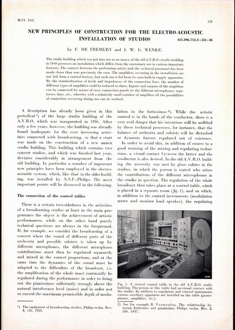
good training of the mixing and regulating techni-cians, a visual contact l:etween the latter and theconductor is also desired. In the old A.V.R.O.·build-ing the necessity was met by glass cabins in thestudios, in which the person is seated who mixesthe contributions of the different microphones inthe studio in question. The regulation of the wholebroadcast then takes place at a control table, whichis placed in a separate room (fig. I), and on which,in addition to the control instruments (modulationmeter and monitor loud speaker), the regulating
Fig. L A central control table in the old A.V.R.O. studiobuilding. The person at this table had no visual contact withthe studio. In addition to regulators and control instrumentsvarious auxiliary apparatus are installed on the table (grarno-phones, amplifiers, etc.).
2) See for example R. Vermeulen. The relationship .be-tween fortissimo and pianissimo, Philips techno Rev. 2,266, 1937.

140 , PHILlPS TECHNICAL REViEW Vol. 6; No. 5 '
elements and the necessary signalling systems, there ;-'elements' aretincluded, while the above-mentionedis also a series 'of auxiliary ,'àppanitus,· such as ,a~xiliary' apparatus of both tables· are housedgramophone 'turntables, 'amplifie~s, a s~itchboa~d' together in .a separate room (the ~'teèhnical' ser-for making the' necessary connections betwe~n vice", see fig. 2). A more detailed description of themicrophones, reg~at'ors: line 'to' the' transmitter, arrangement of the control tables is given in theetc. This arrangement; and the diyision of functions text under fig. 3.thereby involved ~between 'the collaborating tech-nicians was chosen in order to permit as manysided.: The supply of the installationuse as possible of the control tables, for instance, for "'. Roughly speaking, the' electro-acoustic installa-the broadcasting of radio plays in which, different tiion of it studio building is nothing but, a combi-studios sometimes-work t~_gether. " '-,' 'nation of a largenumberof amplifiers which must
In the new studi~ .building, .which is intended ~ supply all kinds of low-frequency voltages at dif-only for the' broadcasting of concerts, 'more empha-, ferent levels to regulators.' lines and .Ioud speakers.:
...........................
'; .....
J8J8J
'Fig. 2. Ground plan of the new A.V,R.O. studio building containing two studios: aIargeconcert hall (1) and à smaller studio for dance music (2). Each studio has a control table.Thetwo control tables are housed in cabins (3,4) between the two studios and have a freeview-of the studios via triple glass windows which furnish adequate acoustic insulation.5 technical service room, 6 hall, 7 conductor's room. The unusual floor plan of the largeconcert hall, which recalls somewhat the sound box of a violin, has been chosen foracoustic reasons. As may; Qe seen the two studios are constructed as entirelyfree-standingboxes inside the building proper, with their own walls and a separate foundation. Thisseparation between studio and outside world, which was also applied in the old A.V.R.O.building, and which has been carried through as far as possible, insures a very good acousticinsulation. (The figure is borrowed from "De 8 en Opbouw" 11, 173, 1940).
sis could be laid on the collaboràtion between con-ductor imd techni~ians. For each of the two studios(a 'large concert hall and a sn:ialler studio for dancemusic) the mixing cabin. and the control table areas it were combined, by bringing the control tableitself into visual contact with the' studio. At -the
• '1_,'- ;..-.;" ' •.-~,'~' .~:J1 "
same tin:ie the mixing and regulati0!l: and the wholedirection of the broadcast"are in' the hands of ä
single person, who, by means of direct contact withconductor' and orchestra; can follow the perfor-mance in. all its detaila.The way in which the con-trol' tables for' the two studios are arranged isshown in the floor plan of fig. 2, while fig. 3 showsthe control table which gives upon thè large concerthall (fig. 4).•In; order t-Okeep the view of the' hallentirely free the table is low and only the operating
For the general arrangement of a studio installatio~the article cited may be referred to 1). Withoutentering into details we shall here consider a fewessential points, the first of which is the supply.The feeding of the many' amplifiers, both with
. heating currents and anode voltages, usually tookplace from a central accumulator battery; this wasthe case in the old A.V.R.O: building. The batterythere 'set .up' 'was, however, not large enough tosupply the installation' of the new building as well,so that the problem of supply had to be consideredanew ..
Now battery feeding of itself has, several objec-jections. Apart from the' high' cost of installationand the complicated maintenance, it is particularly,the mutual coupling of the amplifiers connected. '

MAY 1941 ELECTROACouSTIC INSTALLATION OF STUDIOS 141
Fig. 3. Control table for the large concert hall. Due to the fact that all auxiliary arrange-ments not directly needed during the performance are housed elsewhere (in the TechnicalService room, 5 in fig. 2), the table could be so arranged that an uninterruptedview of the hall is possible. On the five sloping panels are to be found from left to right: 1)switches and signal lamps for connections to the old building, a switch and aregulator for connecting the monitor loud speaker (upper right) to different studios,a microphonefor giving directions to the studios, a set of knobs by means of which indi-cations on a light screen can still be given to the conductor after the beginning of the broad-cast. 2) A group of four microphone regulators for mixing four microphone contributionsand a main regulator for regulating the whole. 3) Switches and signallamps for signallingin the two studios and the corresponding announcer's cabins, and the indicating instru-ment of the modulation meter, with which the peak voltages in the programme are con-trolled. 4) Four more microphone regulators and a main regulator. 5) Telephone apparatus,switches for programme contributions from outside the studio, for instance for mixingsound effects (which can here be furnished from a separate studio of the old building), aswell as keys and knobs for signalling to the second control table.
to the central battery which forms an objection.It is difficult to make the internal resistance of thebattery so small that the. coupling is sufficientlyrestricted, and recourse must therefore be taken tothe introduction of decoupling circuits. Consideringthe very low frequencies (30 cis) which must bedealt which in the amplifiers, the decoupling circuitsmust contain very large self-inductances 3), whichin turn involves considerable current surges uponswitching on and off of an amplifier. These currentsurges lead to click disturbances in all the amplifiersconnected.In addition to these "natural" disadvantages of
battery supply, in our case there was also the fact
3) In telephone networks where the same problem occurs- cross talk between the microphone connected in parallelon a battery - the problem is much simpler, since practi-cally only frequencies above 300 cis are encountered.
that it was a very uneconomical solution for therelatively limited installation of the new buildingto set up a second separ&te central battery. Thiswas the reason why a different sohrtion of the prob-lem was applied, namely the supply of each ampli-fier separately by a built-in supply apparatus.The fact that this solution, in which practically
all coupling between the amplifiers is eliminated,has been applied until now only very seldom, is duemainly to the fear of the hum caused by the 50cis of the A.C. mains. This is indeed a difficultywhich must not be underestimated, especially in astudio where all the amplifiers must be able topass the frequency of 50 cis in full strength, andwhere partially very weak signals occur which aretherefore sensitive to disturbances. The problemcould, however, be solved satisfactorily in thefollowing way.

142 PI-IILIPS TECHNICAL REVIEW Vol. 6, No. 5
Fig. 4. View of the large concert hall. Two hanging microphones on rails may be seen. Nextto the position of the conductor is a movable' signal box with a light screen on which thedirector of the broadcast, seated at the control table, can give several commonly occurringindications to the conductor. Right, sound effect loud speaker for the mixing of back-ground noises. The numerous panels of the walls can be set at different angles in order toinfluence the acoustics of the hall (sound distribution, reverberation).
In order to limit the hum to the required degreethe windings of input and output transformers ofeach amplifier must be especially protected againstinduction by spread lines of force from the supplytransformer. V:ariousmeans of doing this have beenapplied. In the first place the supply transformerworks with a lower iron induction, i:e. not so closeto saturation as is usually the case. This gives ahigher permeability of the iron and therefore lessspreading. Moreover, the supply transformer isplaced in a heavy cast-iron pot which tends toabsorb the spread lines of force and thus diminishes
still more the field observable toward the outside.Furthermore the input and output transformer areplaced in the amplifier panel as far as possible out-side the sphere of the field of the supply transfor-mer. This may clearly be seen in fig. 5: the supplytransformer is at the upper left hand, the inputtransformer at the extreme right, the input trans-former about in the middle at the bottom (becauseit is somewhat less sensitive to hum than the inputtransformer due to the greater signal intensityat that point). The input and output transformersare also housed in pots for shielding. Since it is

MAY 1941 ELECTROACOUSTIC INSTALLATION OF STUDIOS
here a question of shielding fields which are them-selves quite weak, an alloy has been used for thesepots which has a high permeability especially atlow induction. Moreover, for the very sensitive
the earth currents to follow all kinds of complexroutes, but on the contrary they are insulated fromthe panel and connected to a common earth point ofthe amplifier by the straightest possible connections.
Fig. 5. Arrangement of the components in the panel of an amplifier. The supply transformeron the one hand (left) and the input and output transformer on the other hand (right andbelow) are kept as far as possible away from eaeh other. Above the supply transformer maybe seen a "Starto" valve (automatic starting resistance 4), which limits the initial surge andthereby helps to prevent clicking in neighbouring amplifiers. ',~'
input transformer an additional shielding insidethe pot of a special kind of sheet metal is used, whileits winding is "astatic", seefig. 6. By this means thesensitivity for external fields is made very small.An external field gives in generallines of force of thesame direction in the two arms of the transforrnercore, in the two halves of the secondary windingtherefore electromotive forces in the same directionare induced, and since the two halves are connectedin opposition, the resulting voltage is zero. Never-theless the transformer works quite normally fora primary current, because the latter causes a mag-netic field whose lines of force run in oppositedirections in the two arms of the core, so that theinduced electromotive forces in the two halves ofthe secondary winding are added together.
Special attention is also paid to the earth con-nection in order to decrease the hum. The transfor-mer pots, which are to a certain degree coupledcapacitatively with the windings, are not connectedelectrically to the panel, since this would enable
0) See P. C. van der Willigen, Philips techno Rev.I, 205,1936.
The cathodes of the amplifier valves are indirectlyheated.
By these and other measures the hum could besufficiently suppressed. A measurement of the humand noise voltage 5) in the case of the amplifier
t038:184
Fig. 6. Astatically wound transformer. P" P2 halves of theprimary, Sl' S2 halves of the secondary winding. The primarycurrent causes in the two arms of the core opposite lines offorce, an external field, on the other hand, causes lines of forceIn the same direction (broken lines).
5) The 'measurements were carried out with a so-calledpsophometer which takes into account the dependenceon frequency of the sensitivity of the ear.
143
144 PHILIPS TECHNICAL REVIEW Vol. 6, No. 5
type I gave a value of 0.5 mV at the output, t..e.about 75 dB below the normalline level.
Standardization of the amplifiers
In older studio installations, including that of theold A.V.R.O. building, amplifiers of a different typewere used for each function; thus there are micro-phone pre-amplifiers, gramophone amplifiers, pro-gramme amplifiers, coupling amplifiers, monitoramplifiers, etc. The differences betwèén these typeslie in the amplification produced, the input imped-ance, the output, etc.This specialization and close adaptation of each
amplifier to a certain purpose has disadvantagesin manufacture as well as in use. In manufacture,because so many types of amplifiers must be made;in use, because so many amplifiers are needed, onlya few of which are usually in action at one line,and for which the necessary reserves must be athand. In our case, where each amplifier must alsohave a separate supply apparatus, these disadvan-tages were doubly felt.
Therefore a standar diz a tion of the amplifierswas undertaken for the new installation. All micro-phone connections, gramophone pick-ups, regulatorsare adapted to an input impedance of 200 ohms ofthe amplifier to be connected; by giving this anamplification sufficient for all purposes (60 dB),a single type of amplifier (I) proved sufficient. Onlytwo other types of amplifier are then still neededfor the listening to the broadcast at variousspots with monitor loud speakers. The first is acoupling amplifier (1I), which taps off the listeninglines from the programme line (line to the transmitter)in such a way that commutations in the listeningline have no reaction on the programme line, andwhich has a sufficiently high input impedance (5 000ohms) not to affect the level of the programme line.The last is a power amplifier (Ill) which deliversthe necessary' power to supply a loud speaker(7 W). In fig. 10 at the end of this communicationthe way in which the three types of amplifiers areused may be seen.
All three types of amplifiers are two-stage push-pull amplifiers: By the push-pull connection all theconnections can be kept symmetrical with respectto earth, which restricts the possible disturba;nces.Furthermore, due to the push-pull connection, thenon-linear distortion is slight: the maximum dis-tortion factor of the amplifiers of type I is 1 per centabove 100 cis and 2 per cent below 100 cis. Inorder to control the balance each amplifier stagecontains a differential meter which indicates thedifference current of the two valves.
Cable ins.tallation and cross connection panels
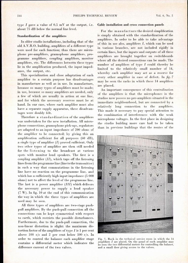
For the manufacture the desired simplificationis simply obtained with the standardization of theamplifiers. In order to be able to take advantageof this in use also, amplifiers I, which can' be usedin various branches, are not included rigidly incertain lines, but the inputs and outputs of all theseamplifiers are brought together on switchboardswhere all the desired connections can be made. Thenumber of amplifiers of type I could thereby belimited to the relatively small number of 14,whereby each amplifier may act as a reserve forevery other amplifier in case of defect. In fig. 7may be seen the racks in which these 14 amplifiersare placed.An important consequence of this centralization
of the amplifiers is that the microphones in thestudios now possess no pre-amplifiers situated in theimmediate neighbourhood, but are connected by arelatively long connection to the amplifiers.This made it necessary to pay special attention tothe combination of interferences with the weakmicrophone voltages. In the first place in designingthe studio building more care had to be takenthan in previous buildings that the routes of the
Q ,Qr.
Ii:::~:~;l~
(( «r r ((_-
Q O~I::;{·;:!
Q Q.
Q
I::~i~i!::;l
I:~fti:~~('((CC. cc cc-
Fig. 7. Rack in the technical service room in which the 14amplifiers I are placed. On the panel of each amplifier maybe seen the two differential meters for controlling the balance,and a small door giving access to the valves.
MAY 1941 ELECTROACOUSTIC INSTALLATION OF STUDIOS 145
a
I~I $ ,Hl
® ®v, !~Jb I I I I I I
I I I I tB@ @V2
I I I I I II I I J I I
.:;8386
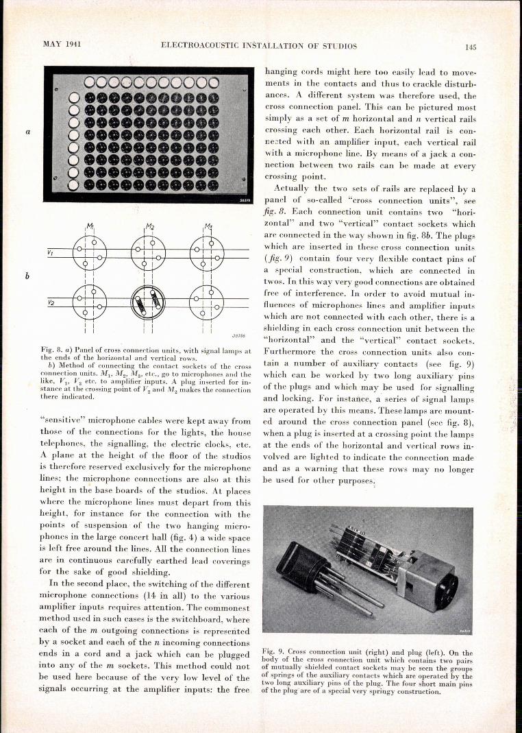
Fig. 8. a) Panel of cross connection units, with signallamps atthe ends of the horizontal and vertical rows.
b) Method of connecting the contact sockets of the crossconnection units. Ml' M2' M3' etc., go to microphones and thelike, Vv V2 etc. to amplifier inputs. A plug inserted for in-stance at the crossing point of V2 and M2 makes the connectionthere indicated.
"sensitive" microphone cables were kept away fromthose of the 'connections for the lights, the housetelephones, the signalling, the electric clocks, etc.A plane at the height of the floor of the studiosis therefore reserved exclusively for the microphonelines; the microphone connections are also at thisheight in the base boards of the studios. At placeswhere the microphone lines must depart from thisheight, for instance for the connection with thepoints of suspension of the two hanging micro-phones in the large concert hall (fig. 4) a wide spaceis left free around the lines. All the connection linesare in continuous carefully earthed lead coveringsfor the sake of good shielding.
In the second place, the switching of the differentmicrophone connections (14 in all) to the variousamplifier inputs requires attention. The commonestmethod us.edin such cases is the switchboard, whereeach of the m outgoing connections is represeritedby a socket and each of the n incoming connectionsends in a cord and a jack which can be pluggedinto any of the m sockets. This method could notbe used here because of the very low level of thesignals occurring at the amplifier inputs: the free
hanging cords might here too easily lead to move-ments in the contacts and thus to crackle disturb-ances. A different system was therefore used, thecross connection panel. This can be pictured mostsimply as a set of m horizontal and n vertical railscrossing each other. Each horizontal rail is con-nected with an amplifier input, each vertical railwith a microphone line. By means of a jack a con-nection between two rails can be made at everycrossing point.Actually the two sets of rails are replaced by a
panel of so-called "cross connection units", seefig· 8. Each connection unit contains two "hori-zontal" and two "vertical" contact sockets whichare connected in the way shown in fig. 8b. The plugswhich are inserted in these cross connection units(fig· 9) contain four very flexible contact pins ofa special construction, which are connected intwos. In this way very good connections are obtainedfree of interference. In order to avoid mutual in-fluences of microphones lines and amplifier inputswhich are not connected with each other, there is ashielding in each cross connection unit between the"horizontal" and the "vertical" contact sockets.Furthermore the cross connection units also con-tain a number of auxiliary contacts (see fig. 9)which can be worked by two long auxiliary pinsof the plugs and which may be used for signallingand locking. For instance, a' series of signal lampsare operated by this means. These lamps are mount-ed around the cross connection panel (see fig. 8),when a plug is inserted at a crossing point the lampsat the ends of the horizontal and vertical rows in-volved are lighted to indicate the connection madeand as a warning that these rows may no longerbe used for other purposes;
Fig. 9. Cross connection unit (right) and plug (left). On thebody of the cross connection unit which contains two pairsof mutually shielded contact sockets may be seen the groupsof springs of the auxiliary contacts which are operated by thetwo long auxiliary pins of the plug. The four short main pinsof the plug are of a special very springy construction.

~,~ .,. ._' .
1'46 PHILIPS TECHNICAL REVIEW . Vol. 6, No. 5
The oûtputs of the 14 amplifiers I also, withthe lines to the regulators, the control instruments,the. transmitter, etc. which must be connectedto them are brought together on a cross con-, neetion panel, In fig. 7 it may be seen how theinput and the output cross connection panels areplaced to the left and right of the racks 'with the14' amplifiers: The signalling system just describedis, so constructed ,that upon inserting à plug in theinput cross connection panel the lamp at the corre-sponding horizontal row of the output cross con-,nection panel also lights up faintly in order to'facilitate the finding of the correct spot for plug-ging in, on that panel, and at the same time, to
indicate 'ag~in: that the amplifier in question is in use.In éon~lusion' in fig. 10 a view of the complete
1'1" _t.. .
installatiou is given. On the cross oonnection panelsas an example the connections are made for 'a'broadcast' in which three microphones in the studiocollahorate (main regulator Hl)' while an acoustichackground (sound effect) is provided by the gram-ophone turntable which, can bé added to theprogramme via the main regulator -H2• At the sametime this background can be 'serit to the studioitself via the regulator R. The commutrica.tions of .the announcer can also pass over the main regulatorH2• Several details are further explained in the textunder, fig. 10.
o
~'_.~G. 'I! . .-~----~~--------ïti d
,tir--"
r-----~_ID+--·1 L__..
HIt H2¥ ~I --' --~~
\~I~'~:~~'r---r-'-__rl~ p,-~+-'+:-1;;' ,_:)+'--j-"ei )-t~-"'~t--t~-+-t-+'--, ! ~:I
I II II II II I
! II· 'II I
~ Kt I II' - I II I I II i II I 11,I' r I :I -, , ' : , I 1
11
1i ,J'_'c'_'£'jJ 1 'I
L_ -: -:--;,---:-;_--(J[]-----I-L;: ~~~ 0-j i----~- ------------i-.-~____ ..M. ... ~ ..7"y_u-----J_t---------------J.. , I ~."' .. I . ·J838T I_____L- c:..'O:-!QJU I 18, . ., " L._:_,?=::==--:---;-'_j
I , "
: " ~. • I. r
Fig. 10. View of the electro-acoustic installation of the new studio building. K; input crossconnection panel, Ku output cross, connection panel, S studio with six micropbonesMl-Ma and sound effect loud speaker (at the same time loud speaker for giving directions);o microphone in the' announcer's cabin, 'G gramophone turntable with correction filter ,F, Hl and H2 main regulators, P:programme line, A monitor lines, I universal amplifier, IJ;coupling amplifier, 111power amplifier, M modulation meter with indicating instrumentR; B cabin with microphone for giving directions C, regulator J.? for sound effect which .can be supplied over Me D from the old building, U telephone apparatus connected tothe telephone ~e T, over which contrib~tions to the programme mayalso be brought in.
""