new multi-functional & economical plcctkingdom.com/upload/file/fp-x0_e_cata.pdf · protocol...
TRANSCRIPT

Programmable Controller
2012.01 panasonic.co.jp/id/pidsx/global
FP-X0
New Multi-functional & Economical PLCBody equipped with combined relay and transistor output
Super-high processing speed80 ns/step (0 to 3000 steps for ST command)
Number of I/O points expandable up to 216 max.When using FP0R extension unit*2
Combined output (Ry+Tr)Tr: 4 points, 0.5 A (Only 2 points for L14)
Built-in 2-axis pulse output50 kHz max.*1
Built-in 2-channel multi-functional analog inputVoltage, thermistor and potentiometer input *2
Built-in calendar/clock*2
Built-in RS485 communication port*3
*1) L14 is 1-axis/20 kHz max. and L30 is 2-axis/20 kHz max.*2) Only for L40R, L40MR, L60R and L60MR models*3) Only for L40MR and L60MR models
L30R
L14R L40R/L40MR L60R/L60MR
Conforming toLow Voltage andEMC Directive

Rich Functions, High Cost-effective.
Strong Lineup, Wide Application.
Maximum 2-channel Communication PortOne RS232C programming port is equipped on the body. And RS485 communication port is also built in L40MR and L60MR.
Modbus-RTUNon-program communication with the devices (such as the temperature controller and the inverter etc.) using global universal industry standard Modbus-RTU (binary) can be realized simply.
PLC LinkIf L40MR and L60MR are used, the sharing of bit data and word data among 16 PLCs (max.) can be realized.
Computer LinkNon-program communication with the devices (such as the display, image processor, temperature controller and wattmeter etc.) using Panasonic open protocol “MEWTOCOL” can be realized simply.
Universal Serial CommunicationIt can generate or send the corresponding commands according to the communication protocol used by the pairing device. In addition, it can also receive the flow data, such as the data from the measuring instrument, bar code reader and RF-ID etc.
Super-high Processing SpeedSuper-high speed of 80 ns/step for 0 to 3000 steps (ST command). 580 ns/step processing speed for 3001 steps or more (Only for L40 and L60).
Program MemoryL14 and L30: 2.5 k stepsL40 and L60: 8 k steps
The Maximum Number of I/O PointsOne control unit can be connected with up to 3 expansion units. Therefore, the maximum number can reach 150 points.In addition, if the expansion FP0 adaptor is used, the maximum number can reach 216 points when the FP0R expansion unit is used. (Only for L40R, L40MR, L60R and L60MR)
2

6 Kinds of Control UnitsL14R, L30R, L40R and L60R: Ry+Tr, ACL40MR, L60MR: Ry+Tr, RS485, AC
11 Kinds of Expansion Units (FP-X)(16 points) × (Ry, NPN, PNP)(30 points) × (Ry, NPN, PNP) (AC, DC)Specific unit for input (E16X)Specific unit for output (E14YR) 3 units max. can be added.E16X, E16T, E16P upgraded to Ver.3 or later can be connected (The number of connected units is limited.)
56 Kinds of Combinations (of I/O number)14 to 150 points (FP0R expansion units excluded)
Built-in 2-axis Pulse Output FunctionL14 is 1-axis pulse output, while L30/L40/L60 are 2-axis, and the pulse output function is built in the body of the controller. Built-in 2-axis type can realize linear interpolation (Only for L40 and L60).
Analog Input FunctionMulti-functional analog input (10 bit, 2-channel) Voltage input (0 to 10 V), thermistor input and adjustable potentiometer input.
3

AFP0RE8X
AFP0RE16X
AFP0RE8YT
AFP0RE8YRS
AFP0RE16YT
AFP0RE16T
AFP0RE32T
AFP0RE8RS
AFP0RE16RS
FP0-A21
FP0-A80
FP0-A04V
FP0-A04I
FP0-TC4
FP0-TC8
FP0-IOL
FP0-CCLS
If the customer can not predict the number of I/O points needed by his machineries and devices in the future, he will feel hesitant and uncomfortable. But, the I/O number of FP-X0 can reach 150 points max. by using the FP-X expansion unit. Therefore, the customer’s discomfort and hesitation can be eliminated. And the number of I/O points can be expanded to 216 by using the FP0R expansion unit. (L14R and L30R don't have the expansion function, so they can not be expanded.)
FP0 expansion adaptor (AFPX-EFP0)
The maximum number of expansion unit is up to 3 units
8-point DC input MIL connector
16-point DC input MIL connector
8-point transistor output MIL connector
8-point relay output screw terminal block
16-point transistor output MIL connector
8-point DC input, 8-point transistor output, MIL connector
16-point DC input, 16-point transistor output, MIL connector
4-point DC input, 4-point relay output, screw terminal block
8-point DC input, 8-point relay output, screw terminal block
Model Specifications
Analog 2-point input , 1-point output
Analog 8-point input
Analog (voltage) 4-point output
Analog (current) 4-point output
Thermocouple 4-point input
Thermocouple 8-point input
I/O LINK unit
CC-Link slave unit
Model Specifications
The maximum number of FP0R expansion unit is up to 3 after all the control units are equipped with adaptors.
A wider range of application can be achieved by using[transistor output],[analog I/O],[thermocouple input]and[I/O LINK (network)].
Only one FP0 expansion adaptor can be installed on the control unit.In addition, two FP-X expansion units can be installed after the adaptor is installed.
Basic Performance (Expansion)Plenty of I/O Points -150 points max.
(If further expansion is made to FP0R expansion unit, the number can be expanded to 216 points max.)
Further expansion and more functions achieved by using the existing FP0R expansion unit easily
FP-X0
L60
2 units max. (60 points)
Besides the supplied expansion cable of 8 cm, 30 cm and 80 cm types are also sold separately. They can be bent or straightened. (The total extension length is within 160 cm.)
E16X, E16T and E16P upgraded to Ver.3 or later can be connected in series up to 3 units.But, E14 and E16 expansion units can not be connected at the right sides of E16X/E16T/E16P (Ver.2 earlier) or E16R/E14YR.
[Expansion]
150 points max.
3 units max.
E30 E30 E30Control unit
The cable between the units can be bent to realize the
side-by-side installation, thus saving the installation space.
96 points max.
Ver.3
Available
Ver.3
Available
Ver.1/2/3
Available
E16X/T E16X/T E16/E14/E30
Ver.3
Available
Ver.1/2
Available
Ver.1/2/3
Not available
E16X/T E16/E14 E16/E14
Ver.3
Available
Ver.1/2/3
Available Available
E16X/T E16/E14/E30 E30
Ver.1/2/3
Available Available
Ver.1/2/3
Available
E16/E14/E30 E30 E16/E14/E30
Product name Powersupply Specifications Model
FP-X E16X - DC input, 16 points AFPX-E16X
FP-X E14YR - 2A relay output, 14 points AFPX-E14YR
FP-X E16R -DC input, 8 points
2 A relay output, 8 pointsAFPX-E16R
FP-X E30R AC16-point DC input
14-point 2A relay outputAFPX-E30R
FP-X E30RD DC16-point DC input
14-point 2A relay outputAFPX-E30RD
FP-X E16T -8-point DC input
8-point transistor (NPN) outputAFPX-E16T
FP-X E16P -DC input, 8 points
8-point transistor (PNP) outputAFPX-E16P
FP-X E30T ACDC input, 16 points
14-point transistor (NPN) outputAFPX-E30T
FP-X E30TD DC16-point DC input
14-point transistor (NPN) outputAFPX-E30TD
FP-X E30P AC16-point DC input
14-point transistor (PNP) outputAFPX-E30P
FP-X E30PD DC16-point DC input
Transistor (PNP) output, 14 pointsAFPX-E30PD
Both of them are 90 mm and can be installed in the cabinet.
E30 E30
4

Max. frequency of pulse output
Output mode
Function
L14: 20kHz(CH0) L30: 20kHz(CH0,1) L40 L60: 50kHz(CH0,1)
Items Specifications
XY workbench
2-axis-control L30/L40/L60 adopted50 kHz x 2 axes
Trapezoidal control, multi-speed operation, JOG operation, original position return, 2-axis linear interpolation (Only L40 and L60)
CW / CCW, Pulse/Sign output
0.5 A of transistor output capacity
(All the outputs can be enabled simultaneously.)
LED indicator
ºC
t
SSR Heater
ThermocoupleStabilized temperature
PWM output
The pulse output function of FP-X0 (1-axis for L14 and 2-axis for L30/L40/L60) is built in the body of the control unit. Compared with the previous PLC that must use the advanced or specific positioning units or more than two multi-axis control devices, FP-X0 only uses one unit basically, thus saving the space and reducing the cost.
Built-in PID command (F356 EZPID) One line of temperature-control program is enough.
A wider range of temperature-control applications is achieved through the use of PLC, such as the multi-section temperature control, temperature control linked with the timer, variable temperature control based on the data calculation results and multi-point temperature control etc. Using new PID commands (F356 EZPID) makes the PID control program simplified substantially than before. It was considered relatively hard to carry out temperature control through PLC before, but now it becomes quite easy. The example shown at the right side is a simple constant temperature control. If you use the F356 command together with the combination operation of touch screen, only one line of program is needed, thus making PID control amazingly simple.
Body equipped with combined relay and transistor output The load capacity of the transistor is up to 0.5 A.
L40 and L60 adopting 2-axis linear interpolation2-axis linear interpolation is a kind of function that controls 2 motor axes and makes the robot arm
and tool head carry out diagonal line moving simultaneously, which is applied in the stacker’s
picking & mounting components, the control of XY workbench and the baseplate cutting etc.
Special FunctionsPulse output function / High-speed counter function
Built-in 4-point high-speed counter
FP-X0
R0
Control code
Y0F356 EZPID, WR1, WX1, DT0, DT100
Measured value Target value Output value Output address
When using the previousF355 command
When using the newPID command F356
Program
Only one lineis needed !
Parameter setting
AT setting
Start bit ON
AT completion
Start bit OFF
Parameter saving
PID command execution
Bit processing
Conversion processingof timer settings
PWM output circuit
PWM output
Frequency setting forPWM output
F356 PID command execution
Touch screen
4-point for 1-phase or 2-point for 2-phase (X0 to X3)
Model
L14
Model
L30
L40/L60
HSC input mode
1-phase
2-phase
HSC input mode
1-phase
2-phase
1-phase
2-phase
Stopping
Outputting
Stopping
Outputting
Stopping
Outputting
Stopping
Outputting
Stopping
Outputting
Stopping
Outputting
20 kHz
20 kHz
20 kHz
17 kHz
20 kHz
20 kHz
20 kHz
13 kHz
50 kHz
36 kHz
20 kHz
16 kHz
20 kHz
20 kHz
20 kHz
16 kHz
When HSC using all the channels
20 kHz
14 kHz
20 kHz
12 kHz
33 kHz
24 kHz
16 kHz
13 kHz
Pulse output (1-axis)
Pulse output (2-axis)
When HSC using 1 channel
When HSC using 1 channel
When HSC using all the channelsOnly L40/L60
X-axis (CH0)
Max. compositespeed50kHz
Y-axis(CH1) 2-axis XY platform L40/L60
Only L40/L60
5

Part Number List Programmable Controller FP-X0 Control Unit
3) Software tools (Refer to Operation Manual for the details. )Product name Software classifi ction Part No.
FPWIN GR
Japanese version with supplied cable kit AFPS10122
English version Full type AFPS10520
English version Lite type AFPS11520
Chinese version Full type AFPS10820
Korean version AFPS10920
FPWIN ProJapanese version AFPS50160
English version AFPS50560
ItemsSpecifi cations
L14R L30R L40R L40MR L60R L60MR
Program editting during Run
Available (Capacity modifi ed simultaneously: 128 steps)
But comments cannot be modifi ed during the process.
Available (Capacity modifi ed simultaneously: 512 steps)
But comments can be modifi ed during the process.
Downloading during Run Available
High-speed counter Note 3) Note 4)
Body input
1-phase, 4-channel (20 kHz max.)
and 2-phase, 2-channel (20 kHz max.)
1-phase, 4-channel (50 kHz max.) and
2-phase, 2-channel (20 kHz max.)
Pulse output/PWM output Note 3) Note 4)
Body output
Pulse: 1-channel
(20 kHz max.)PWM:
1-channel (1.6 kHz max.)
Pulse: 2-channel
(20 kHz max.)PWM:
2-channel (1.6 kHz max.)
Pulse: 2-channel (50 kHz) PWM: 2-channel(3.0 kHz max.)
Pulse catch input/Interrupt program
8 points (High-speed counting and interrupt input included)
Periodical interrupt 0.5 ms unit: 0.5 ms to 1.5 s, 10 ms unit: 10 ms to 30 s
Analog input No
2-channel (For inputting any of the following items in each channel)
Potentiometer inputMin. resistance value of potentiometer:
5 kΩ10-bit resolution (K0 to K1000)
Accuracy ± 1.0% F.S.+ accuracy of external reistors
Thermistor inputFor inputting the resistance value of the
thermistor (Min. resistance value of external
thermistors + external resistance value > 2 kΩ)
10-bit resolution (K0 to K1023) Accuracy ± 1.0% F.S.+ accuracy of
external thermistors
Voltage inputAbsolute max. input voltage: 10 V
10-bit resolution (K0 to K1023) Accuracy ± 2.5% F.S.(F.S. = 10 V)
Calendar/clock No Yes
Flash ROM backup Note 5)
Backup made according to commands of F12 and P13
Data memory(2500 words)
Data memory(8192 words)
Automatic backup when power OFF
Counter: 6 points(C250 to C255)
Process value of the counter: 6 points
(EV250 to EV255)Internal relays: 5 points
(WR58 to WR62) Data memory: 300 words
(DT2200 to DT2499)
Counter: 16 points (C1008 to C1023) Process value of the counter: 16 points
(EV1008 to EV1023)Internal relays: 8 points
(WR248 to WR255) Data memory: 302 words
(DT7890 to DT8191)
Backup battery No Yes (Backup lasting for the whole process)
RS485 communication port No Yes No Yes
Note 1) The actual usable points depend on the combination of the hardware. Note 2) The points of the timer can be added as required. Note 3) The rated voltage is 24 V DC at 25 ℃. The frequency may fall according to the changes
of the voltage, temperature and operating conditions. Note 4) The maximum frequency may vary with the difference of the operating method. Note 5) The allowable writing operation is within 10000 times. Areas to be held and not held
can be specifi ed using the system registers.
Note) For FP-X0: FPWIN GR Ver.2.91 or later FPWIN Pro Ver.6.31 or later
4) Other cables and maintenance parts
Note) The cables for expansion can be extended to 160 cm max.
Product name Specifi cations Part No.
Backup battery For data storage backup and calender/clock
backup AFP8801
FP-X expansion cable Note)
8cm AFPX-EC08
30cm AFPX-EC30
80cm AFPX-EC80
Cable for FP and computer connection (M5 type)
3 m Round D-SUB, 9-pin, L-shaped type AFC8503
Round D-SUB, 9-pin, Straight type AFC8503S
Power cable for FP0 For the adaptor for FP0 expansion, 1 m long AFP0581
Installation bracket for FP0 (Long-strip type)
For FP0 expansion unit, 10 pieces per package
AFP0803
6
FP-X0
Productname
Power supplySpecifi cations
Part No.Program capacity
Analog input
RS485 communication
FP-X0 L14R
100 to 240 V AC24 V DC input, 8 points0.5 A/5 to 24 V DC transistor output, 2 points 2 A relay output, 4 points
2.5 k steps - - AFPX0L14R
FP-X0 L30R
100 to 240 V AC24 V DC input, 16 points0.5 A/5 to 24 V DC transistor output, 4 points 2 A relay output, 10 points
2.5 k steps - - AFPX0L30R
FP-X0 L40R
100 to 240 V AC24 V DC input, 24 points0.5 A/5 to 24 V DC transistor output, 4 points 2 A relay output, 12 points
8 k steps10 bits,
2 channel - AFPX0L40R
FP-X0 L40MR
100 to 240 V AC24 V DC input, 24 points0.5 A/5 to 24 V DC transistor output, 4 points 2 A relay output, 12 points
8 k steps10 bits,
2 channel Available AFPX0L40MR
FP-X0 L60R
100 to 240 V AC24 V DC input, 32 points0.5 A/5 to 24 V DC transistor output, 4 points 2 A relay output, 24 points
8 k steps10 bits,
2 channel - AFPX0L60R
FP-X0 L60MR
100 to 240 V AC24 V DC input, 32 points0.5 A/5 to 24 V DC transistor output, 4 points 2 A relay output, 24 points
8 k steps10 bits,
2 channel Available AFPX0L60MR
Note) 24 V DC input: ± common
1) Control unit
ItemsSpecifi cations
L14R L30R L40R L40MR L60R L60MR
Con
trol
labl
e I
/O p
oint
s Control unit
DC input 8 points,
Relay output
4 points,Transistor
output 2 points
DC input 16 points,
Relay output
10 points, Transistor
output 4 points
DC input 24 points,Relay output 12
points,Transistor output 4
points
DC input 32 points,Relay output 24
points,Transistor output 4
points
When using FP-X E16 expansion I/O units - -
88 points max. (3 expansion units
max.)108 points max.
When using FP-X E30 expansion I/O units - -
130 points max.(3 expansion units
max.)
150 points max.(3 expansion units
max.)
When using FP0R expansion units - -
196 points max.(3 expansion units
max.)
216 points max.(3 expansion units
max.)
Programming method/Control method Relay symbol/Cyclic operation
Program memory Built-in Flash-ROM (Free of backup battery)
Program capacity 2.5 k steps 8 k steps
No of instruction
Basic commands Approx. 114 kinds
High-level commands Approx. 230 kinds
Processing speed
0.08 µs/step for basic commands
0.32 µs for high-level commands
(MV commands)
3 k steps: 0.08 µs/step for basic commands, 0.32 µs for high-level commands(MV commands)
After 3 k steps: 0.58 µs/step for basic commands, 1.62 µs for high-level commands(MV commands)
Basic time 0.15 ms or less 0.18 ms or less 0.31 to 0.35 ms or less 0.34 to 0.39 ms or less
I/O refreshing + basic time
When using E16: 0.4 ms × No. of unitsWhen using E30: 0.5 ms × No. of units
When using FP0 expansion adaptors: 1.4 ms + the refreshing time of the FP0 expansion unit
Mem
ory
for
proc
essi
ng syale
R
External input (X) Note 1) 960 points 1760 points
External output (Y) Note 1) 960 points 1760 points
Internal relay (R) 1008 points 4096 points
Special internal relay (R) 224 points
Timer·Counter (T/C)256 points Note 2) 1024 pointsNote 2)
Timer: (1 ms, 10 ms, 100 ms, 1 s)× 32767, Counter: 1 to 32767
Link relay (L) No 2048 points
Mem
ory
area
Data register (DT) 2500 words 8192 words
Special data register (DT) 420 words
Link data register (LD) No 256 words
File registration (FL) No
Index register (I) 14 words (IO to ID)
Differential points Equivalent to program capacity
Master control relay (MCR) 32 points 256 points
Label number (JP+LOOP) 100 points 256 points
No. of step programs 128 (Engineering) 1000 (Engineering)
No. of subroutines 100 500
No. of interrupt programs Input: 8 programs, timing: 1 program
Sampling trace No Yes
Comments storage All of the I/O comments,explanations and block comments can be saved.(Free of backup battery, 328 k bytes)
PLC link function No Yes
Constant scan In unit of 0.5 ms: 0.5 ms to 600 ms
Password Available (4 or 8 digits)
Upload protection Available
Self-diagnosis function Checks of the watchdog timer and the program syntax
2) Expansion unit FP-X expansion I/O unit and FP0R unit can be used. But FP0 adaptors for FP-X expansion are required when FP0R
expansion units are used.
Specifi cations 1) Performance specifi cations
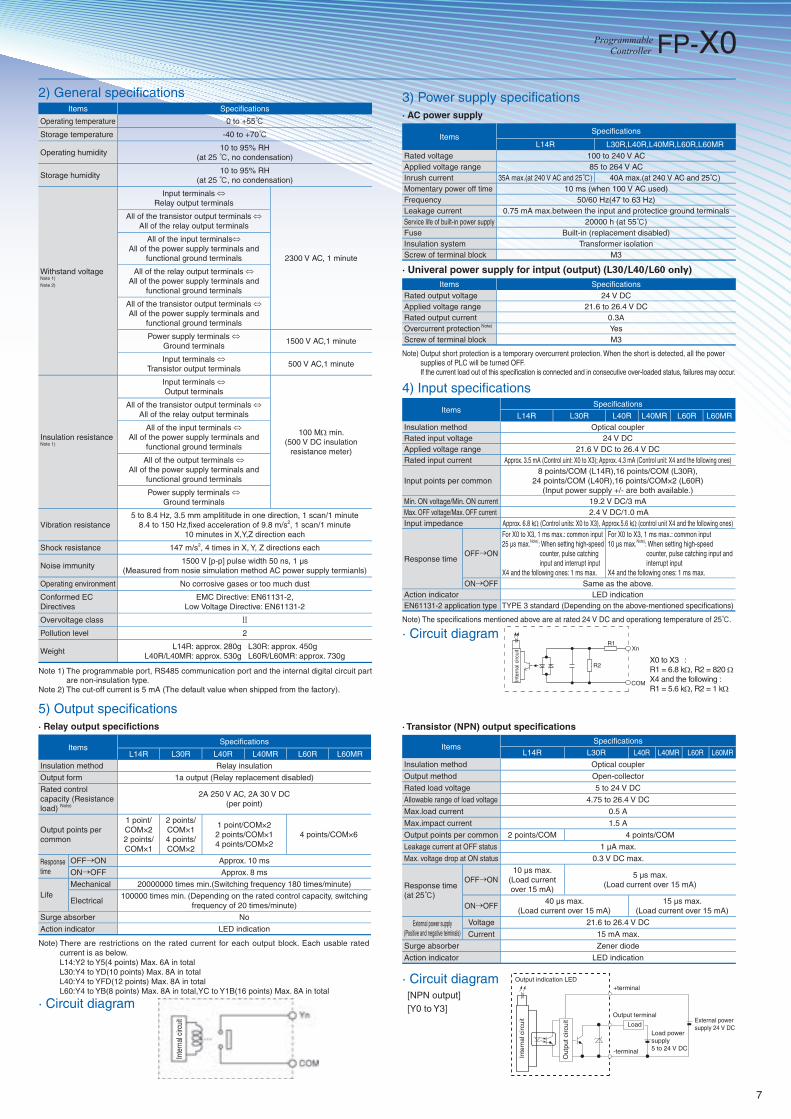
2) General specifi cations Items Specifi cations
Operating temperature 0 to +55℃
Storage temperature -40 to +70℃
Operating humidity 10 to 95% RH
(at 25 ℃, no condensation)
Storage humidity 10 to 95% RH
(at 25 ℃, no condensation)
Withstand voltage Note 1)
Note 2)
Input terminals ⇔Relay output terminals
2300 V AC, 1 minute
All of the transistor output terminals ⇔All of the relay output terminals
All of the input terminals⇔All of the power supply terminals and
functional ground terminals
All of the relay output terminals ⇔All of the power supply terminals and
functional ground terminals
All of the transistor output terminals ⇔All of the power supply terminals and
functional ground terminals
Power supply terminals ⇔Ground terminals
1500 V AC,1 minute
Input terminals ⇔Transistor output terminals
500 V AC,1 minute
Insulation resistance Note 1)
Input terminals ⇔Output terminals
100 MΩ min. (500 V DC insulation
resistance meter)
All of the transistor output terminals ⇔All of the relay output terminals
All of the input terminals ⇔All of the power supply terminals and
functional ground terminals
All of the output terminals ⇔All of the power supply terminals and
functional ground terminals
Power supply terminals ⇔Ground terminals
Vibration resistance5 to 8.4 Hz, 3.5 mm amplititude in one direction, 1 scan/1 minute
8.4 to 150 Hz,fi xed acceleration of 9.8 m/s2, 1 scan/1 minute 10 minutes in X,Y,Z direction each
Shock resistance 147 m/s2, 4 times in X, Y, Z directions each
Noise immunity 1500 V [p-p] pulse width 50 ns, 1 µs
(Measured from nosie simulation method AC power supply termianls)
Operating environment No corrosive gases or too much dust
Conformed EC Directives
EMC Directive: EN61131-2,Low Voltage Directive: EN61131-2
Overvoltage class Ⅱ
Pollution level 2
WeightL14R: approx. 280g L30R: approx. 450g
L40R/L40MR: approx. 530g L60R/L60MR: approx. 730g
Note 1) The programmable port, RS485 communication port and the internal digital circuit part are non-insulation type.
Note 2) The cut-off current is 5 mA (The default value when shipped from the factory).
3) Power supply specifi cations· AC power supply
ItemsSpecifi cations
L14R L30R,L40R,L40MR,L60R,L60MRRated voltage 100 to 240 V ACApplied voltage range 85 to 264 V ACInrush current 35A max.(at 240 V AC and 25℃) 40A max.(at 240 V AC and 25℃)Momentary power off time 10 ms (when 100 V AC used)Frequency 50/60 Hz(47 to 63 Hz)Leakage current 0.75 mA max.between the input and protectice ground terminals Service life of built-in power supply 20000 h (at 55℃)Fuse Built-in (replacement disabled) Insulation system Transformer isolation Screw of terminal block M3
· Univeral power supply for intput (output) (L30/L40/L60 only)Items Specifi cations
Rated output voltage 24 V DCApplied voltage range 21.6 to 26.4 V DCRated output current 0.3AOvercurrent protection Note) Yes Screw of terminal block M3
Note) Output short protection is a temporary overcurrent protection. When the short is detected, all the power supplies of PLC will be turned OFF. If the current load out of this specifi cation is connected and in consecutive over-loaded status, failures may occur.
4) Input specifi cations
ItemsSpecifi cations
L14R L30R L40R L40MR L60R L60MRInsulation method Optical coupler Rated input voltage 24 V DCApplied voltage range 21.6 V DC to 26.4 V DCRated input current Approx. 3.5 mA (Control uint: X0 to X3); Approx. 4.3 mA (Control unit: X4 and the following ones)
Input points per common8 points/COM (L14R),16 points/COM (L30R),
24 points/COM (L40R),16 points/COM×2 (L60R)(Input power supply +/- are both available.)
Min. ON voltage/Min. ON current 19.2 V DC/3 mAMax. OFF voltage/Max. OFF current 2.4 V DC/1.0 mAInput impedance Approx. 6.8 kΩ (Control units: X0 to X3), Approx.5.6 kΩ (control unit X4 and the following ones)
Response time OFF→ON
For X0 to X3, 1 ms max.: common input25 µs max.Note): When setting high-speed
counter, pulse catching input and interrupt input
X4 and the following ones: 1 ms max.
For X0 to X3, 1 ms max.: common input10 µs max.Note): When setting high-speed
counter, pulse catching input and interrupt input
X4 and the following ones: 1 ms max. ON→OFF Same as the above.
Action indicator LED indicationEN61131-2 application type TYPE 3 standard (Depending on the above-mentioned specifi cations)
Note) The specifi cations mentioned above are at rated 24 V DC and operationg temperature of 25℃.
Xn
COM
R1
R2
Inte
rnal
circ
uit
X0 to X3 : R1 = 6.8 kΩ, R2 = 820 ΩX4 and the following : R1 = 5.6 kΩ, R2 = 1 kΩ
· Circuit diagram
5) Output specifi cations · Relay output specifi ctions
ItemsSpecifi cations
L14R L30R L40R L40MR L60R L60MR
Insulation method Relay insulation
Output form 1a output (Relay replacement disabled)
Rated control capacity (Resistance load) Note)
2A 250 V AC, 2A 30 V DC(per point)
Output points per common
1 point/COM×2 2 points/COM×1
2 points/COM×14 points/COM×2
1 point/COM×22 points/COM×14 points/COM×2
4 points/COM×6
Response time
OFF→ON Approx. 10 ms
ON→OFF Approx. 8 ms
LifeMechanical 20000000 times min.(Switching frequency 180 times/minute)
Electrical 100000 times min. (Depending on the rated control capacity, switching
frequency of 20 times/minute)
Surge absorber No
Action indicator LED indication
Note) There are restrictions on the rated current for each output block. Each usable rated current is as below.
L14:Y2 to Y5(4 points) Max. 6A in total L30:Y4 to YD(10 points) Max. 8A in total L40:Y4 to YFD(12 points) Max. 8A in total L60:Y4 to YB(8 points) Max. 8A in total,YC to Y1B(16 points) Max. 8A in total
· Circuit diagram
Inte
rnal
circ
uit
· Transistor (NPN) output specifi cations
ItemsSpecifi cations
L14R L30R L40R L40MR L60R L60MR
Insulation method Optical coupler
Output method Open-collector
Rated load voltage 5 to 24 V DC
Allowable range of load voltage 4.75 to 26.4 V DC
Max.load current 0.5 A
Max.impact current 1.5 A
Output points per common 2 points/COM 4 points/COM
Leakage current at OFF status 1 µA max.
Max. voltage drop at ON status 0.3 V DC max.
Response time (at 25℃)
OFF→ON10 µs max.
(Load current over 15 mA)
5 µs max.(Load current over 15 mA)
ON→OFF40 µs max.
(Load current over 15 mA)15 µs max.
(Load current over 15 mA)
External power supply (Positive and negative teiminals)
Voltage 21.6 to 26.4 V DC
Current 15 mA max.
Surge absorber Zener diode
Action indicator LED indication
· Circuit diagram [NPN output] [Y0 to Y3]
Output indication LED+terminal
-terminal
Output terminal
LoadLoad power supply 5 to 24 V DC
External powersupply 24 V DC
Out
put c
ircui
t
Inte
rnal
circ
uit
7
FP-X0

Dimensions of FP-X0 programmable controller (Unit: mm in)
AFPX0L14R AFPX0L30R
AFPX0L40R AFPX0L40MR
Installation dimensions
AFPX0L60R AFPX0L60MR
86.003.39
90.00
3.54
79.003.11
79.003.11
130.005.12
45.00
1.17
220.008.66
L2 L2
H 2-M4 or 2-Dia. 5
FP-X expansion unit Control unit
L2 H
L14R
82.003.22
L30RL40R , L40MRL60R , L60MRE14 , E16E30
78.00 3.07
122.00 4.80
142.00 5.59
212.00 8.35
52.00 2.05
92.00 3.62
(Tolerance: ± 0.5)
(Unit: mm in)
Item
FP-X0 control unit
FP-X expansion unit
Model
8.00
0.31
79.003.11
90.00
3.54
45.00
1.17
150.005.91
90.00
3.54
79.003.11
45.00
1.17
45.00
1.17
90.00
3.54
No.CE-FPX0 January, 2012 Specifications are subject to change without notice.
Please contact..........
All Rights Reserved © Panasonic Industrial Devices SUNX Suzhou Co.,Ltd. 2012
Panasonic Electric Works SUNX Suzhou Co.,Ltd.No.97.Huoju Road, New District Suzhou, Jiangsu province, China P.R.215009Telephone: +86-512-6843-2580 Facsimile: +86-512-6843-2590