new limitation change to - defense technical information center · new limitation change to...
TRANSCRIPT
UNCLASSIFIED
AD NUMBER
ADB076849
NEW LIMITATION CHANGE
TOApproved for public release, distributionunlimited
FROMDistribution limited to U.S. Gov't.agencies only; Test and Evaluation; 27 Jun83. Other requests for this document mustbe referred to USAF School of AerospaceMedicine, Aerospace Medical Division,Attn: RDO. Brooks AFB, TX 78235.
AUTHORITY
AL/XPPL ltr., 5 Feb 1997
THIS PAGE IS UNCLASSIFIED

Report USAFSAM-TR- 83-27
THE F-16 ONBOARD OXYGEN GENERATING , YSTEM:
PERFORMANCE EVALUATION AND MAN RATING
Thomas C. Horch, Captain, USAFRichard L. Miller, Ph.D.John B. Bomar, Jr., Ueutenant Colonel, USAF, BSCJohn B. Tedor, Major, USAF, BSCRonald 0. Holden, B.A.Kenneth G. Ikels, Ph.D.Paul A. Lozano, B.A.
August 1983
Final Report for Period 1 March 1982 - 31 December 1982
Distribution limited to U.S. Government agencies only;test and evaluation; 27 June 1983. Other requests forthis document must be referred to AMD/RDO.
SUBJECT 7iO EXPORT CONTROL LAWSThis document contains information for manufacturing orusing munitions of war. Exporting this information orreleasing it to foreign nationals living in the United Stateswithout first obtaining an export license violates theInternational Traffic in Arms Regulations. Under 22 USC2778, such a violation is punishable by up to 2 yearsin prison and by a fine of $100,000, J .".C
&%LECTESEP 3 0 1983 3
USAF SCHOOL OF AEROSPACE MEDICINEAerospace Medical Division (AFSC)Brooks Air Force Base, Texas 78235 8 .
OJC FILE COPY

NOTICES .
This final report was submitted by personnel of the Crew SystemsBranch, Crew Technology Division, USAF School of Aero~space Medicine,Aerospace Medical Division, AFSC, Brooks Air Force Base, Texas, under joborder 2761-00-01.
* ~When Government drawings, specifications, or other data are used forK .~ any purpose other than in connection with a definitely Government-related
procurement, the United States Government incurs no responsibility or anyobligation whatsoever. The fact that the government may have formulated orin any way supplied the said drawings, specifications, or other data, is notto be regarded by implication, or otherwise in any manner construed, aslicensing the holder, or any other person or corporation; or as conveyingany rights or permission to manufacture, use, or sell any patented inventionthat may in any way be related thereto.
The voluntary informed consent of the subjects used in this research
was obtained in accordance with AFR 169-3.
This report has been reviewed and is approved for publication.
THOMAS C. HORCHl, Captain# USAF 1ICR7. M`ILLER, Ph.D.-Project Engineer Supervi sor
ROYCE MOSER, Jr.Colonel,, USAF, MCCommander

___.__ ,UNCLASSIFIEDSECURITY CLASSIFICATION OF THIS -AGE (When Data Entered) A
RPRDOUETTO A READ INSTRUCTIONSREPORT DOCUMENTATION PAGE BEFORE COMPLETING FORM
I. REPORT NUMBER 1?_GOVT ACQESSION 0-ECIPIENT'S CATALOG NUMBER
USAFSAM-TR-83-27 A_
4. TITLE (and Subtitle) 5. TYPE OF REPORT & PERIOD COVERED
Final ReportTHE F-16 ONBOARD OXYGEN GENERATING SYSTEM: I Mar 1982 - 31 Dec 1982PERFORMANCE EVALUATION AND MAN RATING 6. PERFORMING ORG. REPORT NUMBER-
7. AUTIOR(#) T. C. Horch, Capt, USAF; R. L. Miller, 8. CONTRACT OR GRANT NUMBER(i)
Ph.D.; J. B. Bomar, Jr., Lt Col, IJSAF, BSC;
J. B. Tedor, Maj, USAF, BSC; R. D. Holden, B.A.;K. G. Ikels. Ph.D.; P_ A- Lnzann. R.A
9. PERFORMING ORGANIZATION NAME AND ADDRESS 10. PROGRAM ELEMEi4T. PROJECT, TASKAREA & WORK UNIT NUMBERS
USAF School of Aerospace Medicine (VNL)Aerospace Medical Division (AFSC) 63246FBrooks Air Force Base, Texas 78235 27610003.
I1. CONTROLLING OFFICE NAME AND ADDRESS 12. REPORT DATE
USAF School of Aerospace Medicine (VNL) August 1983Aerospace Medical Division 3AFSC) 13. NUMBER OF PAGES
Brooks Air Force Base, Texas 78235 5814, MONITORING AGENCY NAME & ADDRESS(if different from Controlling Office) 15. SECURITY CLASS. (of this report)
SP Unclassified
___15a. DECLASSI FICATION/_DOWNGRADINGSCHEDULE
1. DI3TRIBUTION STATEMENT (of this Report)
Distribution limited to U.S. Government agencies only; test and evaluation;27 June 1983. Other requests for this document must be referred to AMD/RDO.
17. DISTRIBUTION STATEMENT (of the absfract entered in Block 20, if different from Report)
IS. SUPPLEMENTARY NOTES
IS. KEY WORDS (Continue on reverse side it necessary and Identify by block number)
Onboard oxygen generator HypoxiaMolecular sieve Oxygen composition controllerLiquid oxygen system Breathing-gas regulatorMan rating
0. ABSTRACT (Continue on reverse side If necessary and identify by block number)
;n onboard oxygen generating system (OBOGS) has been developed by Clifton Preci-sion, according to U.S. Air Force School of Aerospace Medicine (USAFSAM) specifi-cations, for a flight test demonstration in the F-16A aircraft. Prior to actualflight test, the system was cýrtlfied at the USAFSAM as described in this report.Laboratory testing consisted of manned and unmanned tests at ground level, ataltitude, during rapid decompressions, and during acceleration loading. Systemhardware consisted of a molecular sieve concentrator, breathing-gas regulator,,.
DD I 1473 EDITION OF I NOV 65 IS OBSOLETE UNCLASSIFIE// SECURITY CLASSIFICATION OF THIS PAGE (When Date Entered) *. '
2§ A .I

S I UNCLASSIFIED
1SECURITY CLASSIFICATION OF THIS PAGE(Whmn Data Entered)
20. ABSTRACT (Continued)
-seledtor valve, product gas composition controller, backup oxygen supply (BOS),and a breathinq mask. These components replace current liquid oxygen (lox) com-ponents and eliminate the need to service lox converters, resulting in fasteraircraft turnaround time, increased safety, and decreased cost, Laboratory testresults indicated that the F-16A OBOGS was adequate for flight test and that thebreathing-gas composition was physiologically capable of preventing hypoxia and"reducing the occurrence of atelectasis. Furthermore, the OBOGS provided consid-erably less breathing resistance than current lox systems. The concentrator andBOS provided the ability and redundancy to protect the pilot throughout theoperational envelope of the F-16A.' -1
Accessi on For"DTIC TAB
Unannour~adi,•_ JUSt if i cat ion__•
,-', iDist r'ibut ion/
Availability CodesAvail and/or'
Dist Speciald/r
UNCLASSIFIEDSECURI TY CLA SSIFICATION OF THIS PAGE (M~ien Data Entered)

C ON T ENTS
INTRODUCTION.. . . . .................................................. ............... ............. 3
SYSTEM DESCRIPTION........ ............ .................... ... * .*.... 3
Connector and Mask., ................................................. . ..... o . .*. . . . .. 7Monior . .... ... o . ........ ... ... o........ 7
Selector Valve. ........... .*... ** **..****.......... o.......*****, 7
Backup Oxygen System ....*................... 8
PEFOMndcEtr... EAUTO... ......... .... ....... ........ .o ...... ... ... 0.... 9
PEFRAC EVLAIN... ..... o.......... o.......... 28
Ronentrator .............. o...... . o.o............o................ 29
Selector. ... eBO........ o ..oo......... o....... ........ .*...**.****..**.. 44
Rapid Decompression Testing ...... ... *.*..*.* ................... 45Acceleration Testing. .......... .. **.**......... ........ .. .. 45
Rapid Decompression Testing. ................. .......... o........ .. 47
Acce era ion ... ... .... oo.... .. o..58
REOMEDTIN ......... 5
Co c nt a o .. . . . . . . . . . . . . . . . . . . . . . . . . . . . . 5
Re u a o .. . . . . . . . . . . . . . . .. . . . . . . . . . . . . . . 5
Con rol er... .. ... .. ... .. ... .. ... .. ... .. ... .. ... .. ... 1

THE F-16 ONBOARD OXYGEN GENERATING SYSTEM:PERFORMANCE EVALUATION AND MAN RATING
INTRODUCTION
The U.S. Air Force School of Aerospace Medicine (USAFSAM) is developingequipment to replace aircraft liquid oxygen (lox) breathing systems with anonboard oxygen generating system (OBOGS). Prototype OBOG systems have beendesigned and built in previous research and development efforts. NowUSAFSAM is developing a preproduction OBOGS, including hardware development,laboratory testing, and flight testing in an F-16A aircraft. Clifton Preci-sion Instruments and Life Support Division, of LUtton Industries, hasdeveloped OBOGS hardware according to USAFSAM specifications. USAFSAMconductci laboratory testing before completion of F-16 aircraft modificationat General Dynamics and the subsequent flight test at Hill Air Force Base,Utah. This report describes the F-16A OBOGS equipment, laboratory testprocedures, and data and results obtained during the OBOGS performanceevaluation at USAFSAM. Laboratory testing consisted of a simulated-flight-envelope evaluation of all OBOG subsystems to determine equipment limita-tions. This was followed by man rating to determine the equipment's abilityto sustain human physiological requirements.
SYSTEM DESCRIPTION
Components of the F-16A OBOGS include a concentrator, regulator, oxygenmask and connector, monitor, controller, selector valve, backup oxygensupply (BOS), and indicators (Fig. 1). The system was designed to provide aphysiologically acceptable breathing gas for all flight modes of the F-16Aaircraft (representative of current USAF high-performance tactical weaponsystems). The OBOGS is the primary breathing-gas source for the test air-craft up to 25,000-ft cabin altitude. If cabin depressurization shouldoccur above 25,000 feet, the OBOGS will automatically deliver gaseous avia-tors' breathing oxygen--MIL-O-27210D, type 1 (99.5% purity)--to the pilotvia the backup supply. Descriptions of the individual components follow.
Concentrator
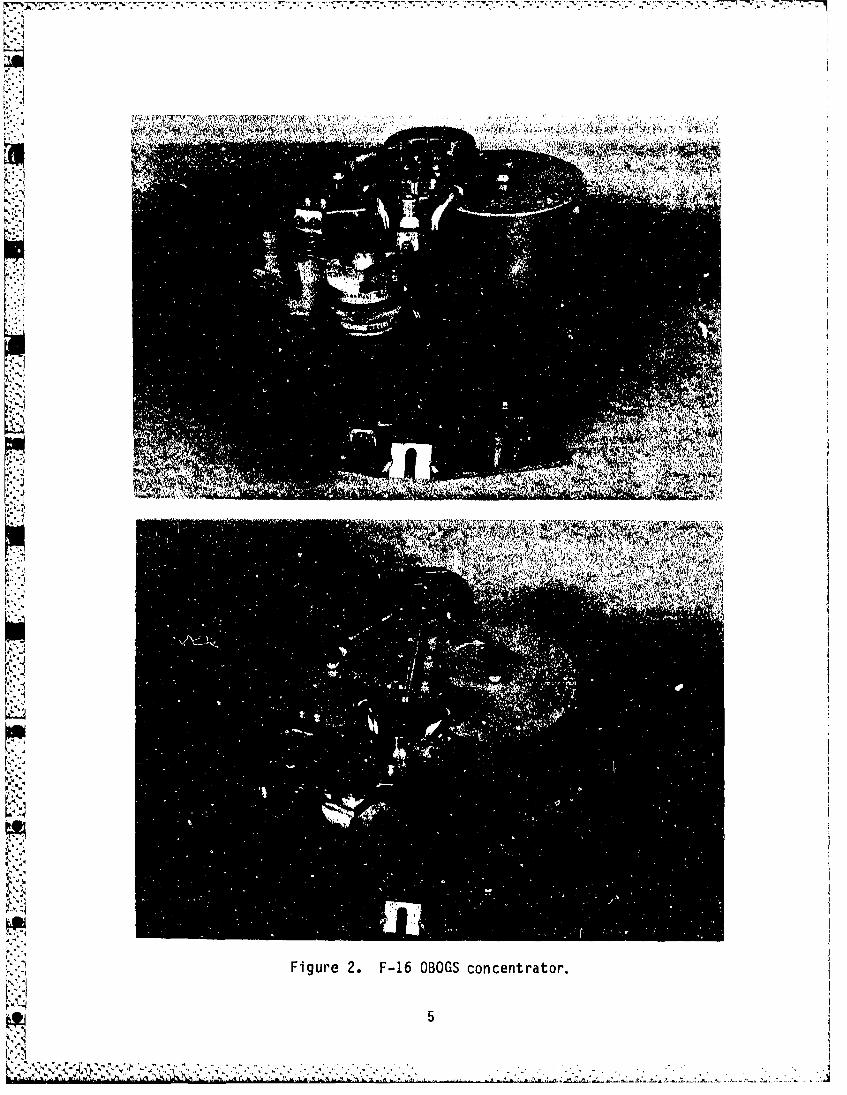
A molecular sieve concentrator is used to produce an oxygen-enrlchedbreathing gas. The concentrator is supplied with engine bleed air from theaircraft environmental control system (ECS). The concentrator (Fig. 2) con-tains an internal nressure regulator which reduces concentrator inlet pres-sure to 37.5 ± 5 psig. Engine bleed air is cycled alternately through apair of molecular sieve beds to produce an oxygen-enriched breathing gashaving a maximum oxygen concentration of 95%, with 5% argon. The oxygenconcentration depends upon inlet air temperature and pressure, exhaust pres-sure (altitude), and the rate of product flow demanded from the concentra-tor. Product gas is supplied to the monitor, controller, shuttle valve,
A 3
• "I

�... 4
OVERBOARDEXHAUST DUMP
HCONNECTOR
MASK
p4I.-
Figure 1. F-16A OBOGS functional diagram.
K'9.
4
. . -. >.
T~ - ,- -- - .-
U------
74 ~ ----
Figure 2.. F-16 OuuuS concentrator.
i~5

breathing regulator, and mask. A fiberglass shroud encloses tV concentra-tor to reduce heat gain or loss (Fig. 3).
NN' t4'
Figure 3. F-16 OBOGS concentrator with shroud.
Regulator
The pilot's breathing-gas regulator reduces inlet gas supply pressureto a level suitable for human respiration. The regulator inlet pressure isapproximately 38 psig when the regulator is supplied from the concentrator,and approximately 60 psig when supplied from the BOS. (BOS pressure isreduced from a nominal 1800 psig to 60 psig in the selector val le.) Theregulator provides a positive static safety pressure of approximately 1inch-water-gauge (in-wg) at all cabin altitudes up to 38,000 feet. At38,000-ft cabin altitude, a pressure breathing feature delivers an increasedpositive pressure schedule to the mask. The regulator is a 100% pressuredemand regulator and does not dilute the breathing gas with cabin air. Apress-to-test button on the regulator provides 17-in-wg pressure to themask-to-test mask fit.
6

Connector and Mask
The OBOGS includes a standard USAF CRU-60/P connector as well as stan-dard oxygen hoses. A modified United Kingdom type P/Q aviation oxygen maskand the USAF MBU-5/P or 12/P masks will be used in the flight test demon-stration. The P/Q mask is preferred by USAFSAM because of its reducedbreathing resistance when compared to the standard MBU 5/P or 12/P mask.Resistance to breathing is less in the P/Q mask because it has separateinspiratory and expiratory valves versus a combined valve in the MBUmasks. For this flight demonstration, the P/Q mask was modified to be com-patible with USAF communication systems and to allow the mask to be attachedto the standard USAF HGU-26/P helmet with bayonet receivers.
Monitor
The OBOGS incorporates a polarographic-type oxygen monitor to measurethe partial pressure of oxygen (P0 2 ) produced by the concentrator. Thismonitor provides a low-oxygen warning to th. pilot and automatically acti-vates the BOS if the concentrator is producing an insufficient oxygen par-tial pressure. The monitor's output is an adjustable electrical signalwhich is linearly proportional to P02 . This signal is compared with aninternally generated reference voltage. When the monitor output falls belowthe reference voltage, a binary signal is generated which activates the BOSand illuminates an OXY LOW caution light. The reference voltage and monitorgain are adjusted to activate the BOS and to illuminate the indicator lightswhenever the concentrator product gas P02 falls below 195 mmHg. A systempress-to-test button on the regulator activates a test of the monitor andautomatic switchover to BOS. When the test is activated, ambient cabin airis delivered to the monitor and produces a low P02 condition. When the
K. press-to-test is released, OBOGS product gas is delivered to the monitor andbleeds overboard through the monitor case.
Controller
The OBOGS incorporates a controller to adjust the product gas composi-tion. Product gas oxygen concentration should be no greater than 70% fromground level to 17,000-ft cabin altitude. The product gas composition iscontrolled by bleeding a prescheduled amount of product gas into the cabin.The amount of gas (product bleed flow) bled into the cabin is a function ofcabin altitude and is also affected by the amount of product gas deliveredto the crewmember. The controller is strictly a pneumatic device and doesnot incorporate feedback from the oxygen monitor.
Selector Valve
The OBOGS selector valve is used to manually and/or automaticallyselect the breathing-gas source from either the OBOGS concentrator or theBOS. The selector valve has four positions: OFF, OBOG, NORMAL AUTO, andBACKUP OXY. In this report these will be referred to as OFF, OBOG, AUTO,and BU respectively. The crewmember can at any time manually select backupoxygen by placing the selector valve at BU. With the valve in this
7

position, stored oxygen from the backup supply will be delivered through theshuttle valve and regulator to the mask. With the selector valve at OFF,the BOS bottles are mechanically locked out and cannot supply the regula-tor. The OFF position allows the system test to be completed withoutdepleting the BOS and also inactivates the BOS when the concentrator or air-craft engine is not operating. With the selector valve at AUTO, the systemwill automatically switch to BOS if the OBOGS product-gas oxygen partialpressure falls below 195 mmHg or if cabin altitude exceeds 25,000 feet.With the selector valve at OBOG, below 31,000-ft cabin altitude the pilotcan manually reselect OBOGS product gas. Above 31,000 feet, the systemautomatically reselects the BOS. With the selector valve set at either OBOGor AUTO,- the system will select BOS whenever regulator inlet pressure isless than 10 psig. When the BOS is supplying the regulator, the shuttlevalve will pneumatically switch back to OBOG product gas when the BOSbottles are depleted.
Backup Oxygen System
The backup oxygen system consists of two 50-in 3 high-pressure (2000
psig) gaseous oxygen cylinders having a combined capacity of 200 liters NTP(normal temperature and pressure). The two bottles are connected in paral-lel with the necessary fittings to allow ground filling. A high-pressurehose connects the BOS bottles to the selector valve which reduces the pres-sure to 60 psig and delivers backup oxygen to the regulator when selected.
Indicators
An oxygen pressure gauge (bailout-bottle type) indicates the pressureremaining in the BOS, and a yellow caution light mounted on the selectorvalve indicates when the selector valve is in the BU position. This lightalso illuminates if the cabin altitude is above 31,000 feet (at this alti-tude the system automatically selects BOS) or if the selector valve is in
the AUTO position and a system malfunction causes automatic switchover tothe BOS. An OXY LOW caution light illuminates whenever the oxygen monitor
detects less than 195-mmHg P02 or whenever OBOGS product pressure fallsbelow 10 psig. Illumination of the OXY LOW light also causes the resettableaircraft master caution light to illuminate. The system press-to-testbutton causes both the OXY LOW and selector valve lights to illuminate. Acockpit-mounted power switch controls electrical power to the concentratorand activates the rotating inlet valve.
8

PERFORMANCE EVALUATION
The OBOGS was evaluated to determine system characteristics and oper-ating limitations. Concentrator inlet pressure and temperature, exhaustpressure (altitude), and product flow were varied while product gas composi-tion and pressure were measured. Rapid decompression and acceleration test-ing were also accomplished. A description of the tests and test resultsfollow.
Concentrator
The OBOGS concentrator was tested as a separate component to ascertainits performance characteristics. A pressurized air supply was plumbedthrough a circulation heater to the concentrator inlet port. The concentra-tor was located inside an "aircraft-altitude" chamber and was instrumentedto monitor/record inlet air temperature, pressure, and flow; exhaust temper-
r ature; electrical motor current; and temperature inside the concentrator'sshroud. The concentrator exhaust gas was vented to this chamber whileprodu!ct gas was plumbed through actual F-16 oxygen system tubing to anadjoining "cabin-altitude" chamber. A digital controller was used tocontrol the two altitude chambers so that the concentrator would be main-tained at aircraft altitude with the product gas vented to cabin altitude.The altitude chambers were controlled to mimic the aircraft pressurization
L schedule. A metering valve at the end of the concentrator product gas linecontrolled output flow, and instrumentation recorded product gas composi-ton, flow, and temperature.
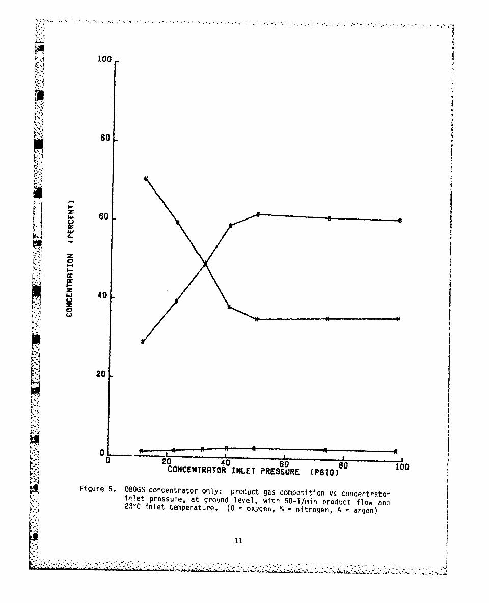
A series of ground-level tests were made to determine product gas com-position as a function of concentrator inlet pressure and outlet flow.Figure 4 illustrates the relationship between concentrator inlet pressureand product gas composition at a steady product flow of 20 1/mmn and withconcentrator inlet air at ambient temperature (230, or 73'F). The oxygen,nitrogen, and argon curves tend to flatten out above 40-psig inlet pressureII.due to the concentrator's internal pressure regulator. Note that oxygenconcentration is considerably lower with low inlet pressures; however, thisshould not present a problem in the F-16 because minimum inlet pressure isexpected to be 40 psig. Figure 5, except for product flow of 50 1/mmn, issimilar to Figure 4. Figure 6 displays oxygen concentration as a functionof concentrator inlet pressure and product flow. This curve (ground level)was obtained with ambient inlet temperature and shows product flow curvesfor 20, 50, and 100 !,'min. Higher product flows decrease the oxygen concen-tration in the product gas. Figure 7 is a plot of product gas compositionversus product gas flow. This data was obtained at ground level with theinlet pressure set at 40 psig and with inlet air at ambient temperature.
At this time it is advantageous to explain some terminology that willbe used throughout the remainder of this report. Concentrator inlet pres-sure was always gauge pressure referenced to aircraft (concentrator) alti-tude. , Thus, at ground l evel , 40 ps ig i nl et pressure was 40+14.4, or 54.4psia (absolute); and at 10,000-ft aircraft altitude, 40 psig inlet pressurewas 4U+10.1, or 51.1 psia; and product flows were ATPD (ambient temperature,pressure, dry) liters per minute. Therefore, a product flow of 50 1/min at10,000 feet was equivalent to a ground-level flow of 5OX (10.1/14.4), or35.1 1/mmn.
9

100
80
L *J
ILI0 6
ccz
40
zKZ
Ca
20
0 20 40 s0 80 100CONCENTRRTOR INLET PRESSURE (PSIGS
Figure 4. OBOGS concentrator only: product gas composition vs concentratorinlet pressure, at ground level, with 20-1/min product flow and23 0C inlet temperature. (0 = oxygen, N = nitrogen, A = argon)
10
100
80i soo
I
z60
ILi
z
"W 402 0
I,,,,,
20
00 S,-,0 20 40 60 80 1.00CONCENTRATOR INLET PRESSURE (PB1GsL
Figure 5. OBOGS concentrator only: product gas composition vs concentratorinlet pressure, at ground level, with 50-1/min product flow and23'C inlet temperature. (0 oxygen, N nitrogen, A = argon)
-t 11

"+I'too
• ~90 '
80,,
5-
o s
I / IU 70
C.)
z
C. prd50lw o 0 0 ndI0Iri. 3•23 5,I=I0-
40
30
a 040 60 so 100CONCENTRATOR INLET PRESSURE (PSTGJ
Figure 6. OBOGS concentrator only: oxygen concentration vs concentratorinlet pressure, at ground level, with 23*C inlet temperature andproduct flows of 20, 50, and 100 I/min. (2 20, 5 SO, 1 100I/mi n)
12

400
:4a
260
wOf
40 2.
20.
0 20 40 60 80 1O00:
PROOUCT FLOW (LITERS/MIN)
Figure'7. OBOGS concentrator only: product gas composition vs product flowat ground. level, with 230C inlet temperature and 40-psig inletpressure. (0 oxygen, N = nitrogen, A argon)
13

71 o- ,
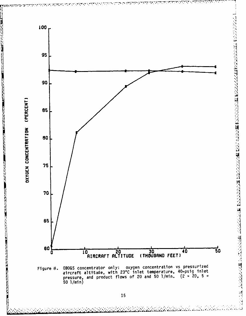
Oxygen concentration increased with increasing altitude, as shown inFigure 8, for the higher product flow of 50 1/min ATPD. This data wasobtained with a constant inlet pressure of 40 psig and with inlet air atambient temperature. As aircraft altitude increased, cabin altitudeincreased according to the F-16 aircraft pressurization schedule: normo-baric altitudes are maintained to 8,000 feet; the cabin maintains anisobaric altitude of 8,000 feet while the aircraft climbs to 23,000 feet;and above 23,000 feet the cabin maintains a 5 psi differential above ambientpressure Except for simulating an unpressurized cabin (equal aircraft and
cabin altitudes), Figure 9 is similar to Figure 8.
The remaining variable that affected product composition was heat. The.primary source of heat in the F-16 is heat of compression in the enginebleed air. Engine bleed air in the F-16 is conditioned by the aircraftenvironmental control system; however, concentrator inlet air temperatureremains elevated above ambient outside-air temperature. Aircraft installa-tion was simulated in the laboratory by heating the inlet air temperatureand allowing the concentrator to reach equilibrium, as determined by moni-toring exhaust temperature and temperature inside the concentrator shroud.
The ground-level effect of temperature on product composition is shownin Figure 10. This data was obtained with concentrator inlet pressure of 40psig and indicates that oxygen concentration was lower at 80°C (176 0 F) thanat 23*C ambient inlet air temperature. Figure 11 shows the ground-levelrelationship between oxygen concentration and concentrator inlet pressurewith 80*C inlet air.
The oxygen concentration at altitude is shown in Figure 12 for threeproduct flows--20, 50, and 100 I/min; inlet temperature was 80'C and concen-"trator inlet pressure, 40 psig. Figure 13 compares oxygen concentration ataltitude for 20 and 80 0C inlet air with a steady product flow of 50 ]/min.
After concentrator performance was determined, the cockpit-mounted com-ponents were added to obtain system performance.
14
'1** - 2 2.'. . 2 ..•.. ..
ito
95 ,1
90
:2~
RIRC~RfFT RLTITUDE (THOUSAND FEET) :
* FigureS8. OBOGS concentrator only: oxygen concentration vs pressurized -. iaircraft altitude, with 230 C inlet temperature, 40-psig inlet -,
pressure, and product flows of 20 and 50 1/mai. (2 = 20, 5 = ..501/mmn)
Z 71
.z. .. -...
W ' 7 ' .. ,".' . • - . ,.: •.•,: ,. • ; :. • • • ,• •• •• • •. . . . . ..

100
95
90
z 85
V "•
z
• oso
z
z
70
":" 85
"'". I , I
0 to 20 30 40 50AIRCRAFT ALTITUDE (THOUSAND FEET)
Figure 9. OBOGS.concentrator only: oxygen concentration vs unpressurizedaircraft altitude, with 23*C inlet temperature, 40-psig inlet".-' pressure, and product flows of 20 and 50 I/min. (2 = 20, 5 =
50 1/mln)
16. . . . .

2a100
90
80
ON
70
z
II
so :- 60
50
40
30
0 20 40 60 80 100K PRODUCT FLOW (LITERS/HIN)
Fi gure 10. OBOGS concentrator only: oxygen concentration vs product flow,at ground level, with 40-psig inlet pressure and 23 and 80%Cinlet temperatures. ( 2 = 23, 8 = 80*C)
17

-. .
* *(
60,
liti
so•
I A
"80
€l:1
z go
70
h 20 40 so so Laol~i•,• CONCENTRATOR INLET PRESSURE (P$IG, !i
Figure 11. OBOGS concentrator only: oxygen concentration vs inlet pressure, .Sat ground level, with 80*C inlet temperature and product flowsI!of 20 and 50 I/min (2 =20, 5 =50 I/min)118
k , I!I.- -
p]

100
90
oe
0-z
I- 70
ZZ
40 , , , , .. . i_0 10 20 30 40 so so
AIRCRAFT ALTITUDE (THOUSAND FEET)1
Figure 12. OBOGS concentrator only: oxygen concentration vs pressurizedaircraft altitude, with 800C inlet temperature, 40-psig inletpressure, and product flows of 20, 50, and 100 I/min. 2 =20,5 =50, 1 =100)
z1

IIT,
100
90
I.o-
130
Zd
WWZ
Li~
170L60
50..
0 10 20 30 40 50 60s
RIRCRAFT ALTITUDE (THOUSAND FEET) "
Figure 13. OBOGS concentrator only: oxygen concentration vs pressurizedaircraft altitude, with 40-psig inlet pressure, 50-1/min
product flow, and inlet temperatures of 23 and 80 0 C. (2 = 23,8 = 80 0C)
20I• ' .
. .. . .

Controller
The OBOGS controller adjusts product gas composition by bleedingproduct gas into the cabin at a prescheduled rate. Therefore, total concen-trator product flow was the sum of pilot inspiratory flow plus controllerbleed flow. Figure 14 illustrates the desired oxygen concentration band:The minimum concentration as 195 mmHg, which is above the physiologicalequivalent to breathing air at sea level, and the maximum concentration wasintended to prevent or minimize the occurrence of acceleration-inducedatelectasis. Figure 14 also shows the concentration that would be deliveredto the pilot with minute volume flows of 10 and 50 1/min at an inlet temper-ature (f 800C, an inlet pressure of 40 psig, and no controller bleed flow.
100 71100
0I /
-- 80- -00• ,J
70 R" MS~DESIRED MAXIMUM /
zg /
70 C II MWM~
040 . - "CO T CONCENTRATION
20• I II I I l I
0 5 8 10 15 20 25 30 35CABIN ALTITUDE (THOUSAND FEET)
N I I I I0 5 82326.5 36.5 49 75
PRESSURIZED AIRCRAFT ALTITUDE (THOUSAND FEET)
Figure 14. Desired concentration range and OBOGS uncontrolled output vsaltitude with product flows (Qp) of 20 and 50 1/min.
21
p74
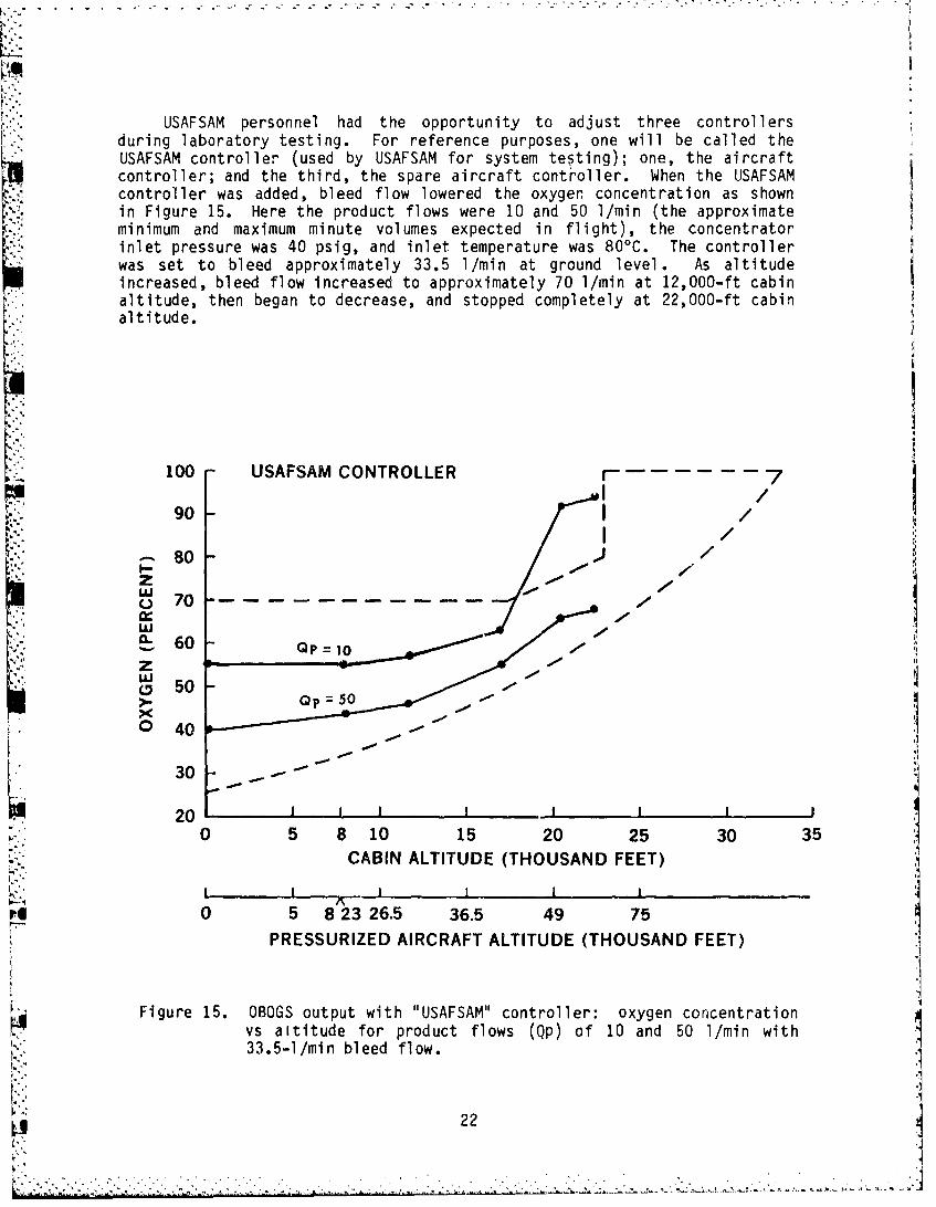
USAFSAM personnel had the opportunity to adjust three controllers
during laboratory testing. For reference purposes, one will be called theUSAFSAM controller (used by USAFSAM for system testing); one, the aircraftcontroller; and the third, the spare aircraft controller. When the USAFSAMcontroller was added, bleed flow lowered the oxygen concentration as shownin Figure 15. Here the product flows were 10 and 50 1/min (the approximateminimum and maximum minute volumes expected in flight), the concentratorinlet pressure was 40 psig, and inlet temperature was 800C. The controllerwas set to bleed approximately 33.5 1/min at ground level. As altitudeincreased, bleed flow increased to approximately 70 1/min at 12,000-ft cabinaltitude, then began to decrease, and stopped completely at 22,000-ft cabinaltitude.
100 USAFSAM CONTROLLER f --- - 790 -
80 //so - z/
0 70 --- 0/
•.:.Z 0 5 810 15 000,3 3
60 -
8 2S50 5
vs altitude for product flows (Qp) of 10 and 50 1/mi with3
33.5-1/min bleed flow.
22
".•."'j•,• .• ? ,I . ,-- - - ,.. '..''V' ',*. .*-."..-.-. . & . ' '. .,, , ,"..?'• a••''- '',''•-';''''=-'''•' '' • .. ..
Ki
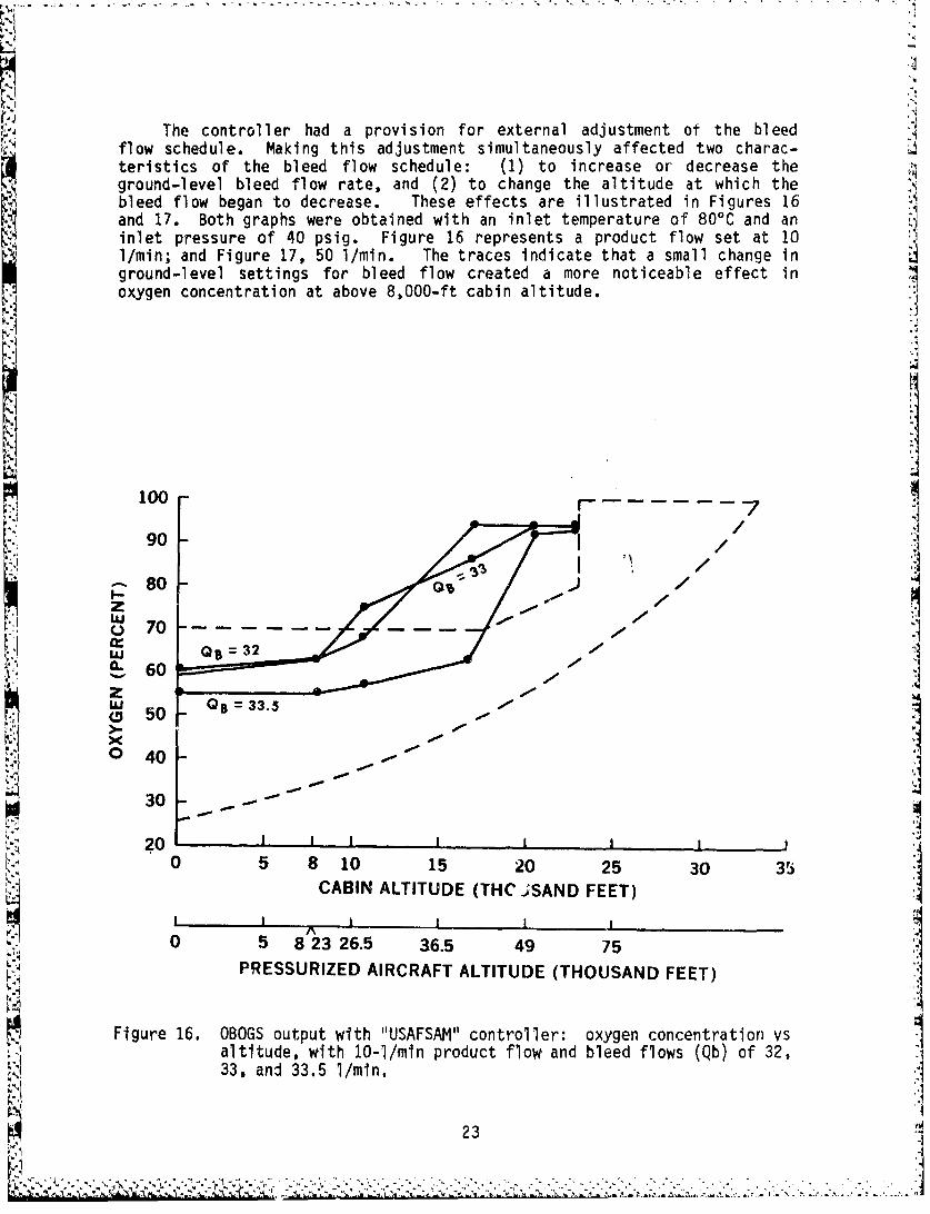
The controller had a provision for external adjustment of the bleedflow schedule. Making this adjustment simultaneously affected two charac-teristics of the bleed flow schedule: (1) to increase or decrease the
ground-level bleed flow rate, and (2) to change the altitude at which thebleed flow began to decrease. These effects are illustrated in Figures 16and 17. Both graphs were obtained with an inlet temperature of 80°C and aninlet pressure of 40 psig. Figure 16 represents a product flow set at 101/min; and Figure 17, 50 I/min. The traces indicate that a small change inground-level settings for bleed flow created a more noticeable effect inoxygen concentration at above 8,000-ft cabin altitude.
100 7
ioi /Sz /
607o 50 /
60-40L' QB =33.5
30 -
0 5 8 10 15 20 25 30 35
CABIN ALTITUDE (THC JSAND FEET)
I I p I I
0 5 823 26.5 36.5 49 75
PRESSURIZED AIRCRAFT ALTITUDE (THOUSAND FEET)
Figure 16. OBOGS output with "USAFSAM" controller, oxygen concentration vsaltitude, with 10-1/min product flow and bleed flows (Qb) of 32,33, and 33.5 I/min,
,,.23.

I
During laboratory testing, the controller was set to obtain optimum 'j
performance; i.e., bleed flow was set to keep the oxygen concentrationwithin the band over the widest range in altitude and demand flow. Figure17 indicates that with a product flow of 50 I/min, a bleed flow setting of34.0 l/ min (ground level) caused the backup to activate at approximately16,000 feet. Figure 16 indicates that with a product flow of 10 1/min, theoptimum performance was obtained with the bleed flow set at 33.5 1/min whichproduced results as shown in Figure 15.
100 - r90I /
S780 /
040
70 -
0 5 810 15 20 25 30 35
I I I III:-
0 5 8 23 26.5 36.5 49 75-,
PRESSURIZED AIRCRAFT ALTITUDE (THOUSAND FEET)-:"1
Figure 17. OBOGS output with "USAFSAM" controller: oxygen concentration vs'altitude, with 50-1./mmn product flow and bleed flows (Qb) of 32, ,,33, 33.5, and 34 1/m.
224Llq
C A ( FEET)0 5 823 26.5 36.5 49.7

The USAFSAM controller was set as shown in Figure 15; the aircraft con-troller, as in Figure 18; and the spare, as in Figure 19. The same proce-dure was used to obtain the optimum schedule for each controller. Theworst-case condition was 40 psig and 80%C; this was the minimum pressure andmaximum temperature expected in the F-16. With these settings, the product
flow was set for 50 1/min and the bleed flow was adjusted to keep the P02above 195 mmHg, thus keeping the BOS off during normal operations. Thethree controllers had slightly different characteristic curves for productflows of 10 and 50 1/min. This difference is believed to be caused byslight variations in the springs of the three different controllerdiaphragms.
100 r
9 0
S80 .
z W7707
(L 60
60 '00050
0 40 QP 60
0 5 8 10 15 20 25 30 35
CABIN ALTITUDE (THOUSAND FEET)
!I I I I IA
0 5 8 23 26.5 36.5 49 75PRESSURIZED AIRCRAFT ALTITUDE (THOUSAND FEET)
Figure 18. OBOGS output with "aircraft" controller: oxygen concentration vsaltitude, wIth 27-1/min bleed flow and product flows (Qp) of 5,10, 50, and 60 1/min.
25
..................

9o II.,
100 -90 /
8 j80W/
70 I
20 10 .00
K0 5 8 10 15 20 25 30 35CABIN ALTITUDE (THOUSAND FEET)
I I I I I IK0 5 8 23 26.5 36.5 49 75PRESSURIZED AIRCRAFT ALTITUDE (THOUSAND FEET)
Figre 9. BOG ouputwith "spare aircraft" controller: oxygen-
concentration vs altitude, with 27-1/min bleed flow and •product flows (Qp) of 10 and 50 1/min.
626
I,
Vz
Wq
*.~~~~~~4Q *. -.. - ,-. .
.!
200 5 10 5 2 25 0 3
•!•:.;:.:.•.•:`.?•`:.:;:.•;;:;::•:.:;.::.?:•÷;.`CAB..:;..IN ALTITUDE (THOUSAND FEET):•:.•;c•.•..•.:/ .`•,:/...•° :•`•`::•.`•`..:.••....:.

At the time the controllers were set, the inlet air temperature to theOBOGS on the aircraft was not well defined. It was believed that the maxi-mum temperature would not exceed 80'C; however, normal operating tempera-tures would likely be less than 800 C. Figures 20 and 21 show the effectthat inlet air temperature had on oxygen concentration for steady product-gas flows of 10 and 50 1/min, respectively, using the USAFSAM controller.Figure 21 indicates that the BOS would be activated if inlet temperature waselevated above 90°C with 50 I/min product flow. However, the flight testprogram was not expected to encounter 50 1/min sustained product flows orhigh inlet-air temperatures at the high altitudes where the P02 could fallbelow 195 mmHg.
1oo -/
100[ 1 1 52904
s 80-oC oC .
S70 - - - - - -o,¢
60 I Tin =00
S50 •
3 0 s • "
20 1
0 5 8 10 15 20 25 30 35CABIN ALTITUDE (THOUSAND FEET)
I I I I I .IA823 26.5 36.5 49 75
PRESSURIZED AIRCRAFT AL(ITUDE (THOUSAND FEET)
Figure 20. OBOGS output with "USAFSAM" controller: oxygen concentration vsaltitude, with 10-1/min product flow and inlet temperatures(Tin) from 50 to 1000 C.
27
V .. "." "." ,; •• ,"•"- • ,-"- •. . . . , . . . . . . "," '" " " " " "-

*.oo- rw 7
90 /I /
.80 J
S 70 110 /z 6 -
5J 0 0C 0 0 C *
S60 "
3 0 - .
20 I I I0 5 8 10 15 20 25 30 35
CABIN ALTITUDE (THOUSAND FEET)i I I I I
0 5 82326.5 36.5 49 75PRESSURIZED AIRCRAFT ALTITUDE (THOUSAND FEET)
Figure 21. OBOGS output with "USAFSAM" controller: oxygen concentration vsaltitude, with 50-1/min product flow and inlet temperatures (Tin)from 50 to 1000C.
Monitor
The OBOGS oxygen monitor output was compared in the laboratory withthat of a Perkin-Elmer respiratory mass spectrometer and found to be lin-ear. The monitor output voltage was externally adjustable from the frontcover of the regulator/monitor package. Removing the front cover exposedelectrical terminals that let the monitor output voltage be read and allowedair to enter the monitor cavity. A potentiometer was adjusted so that themonitor output voltage read the desired voltage as calculated by the formula
Desired monitor output voltage = (A X B)/29.92
where A = the local barometric setting in inHg, and B = percent of oxygen ingas entering the monitor cavity (21% for air).
28

Regulator
The F-16A OBOGS regulator is a low inlet pressure, nondiluting,pressure-demand regulator that delivers approximately 1-in-wg positivestatic safety pressure at all altitudes from ground level to 38,000-ft cabinaltitude, where pressure breathing begins. The regulator was designed toreduce resistance to breathing and to provide pressure breathing for alti-tude protection up to 50,000 feet. Regulator evaluation consisted of bothstatic and dynamic testing.
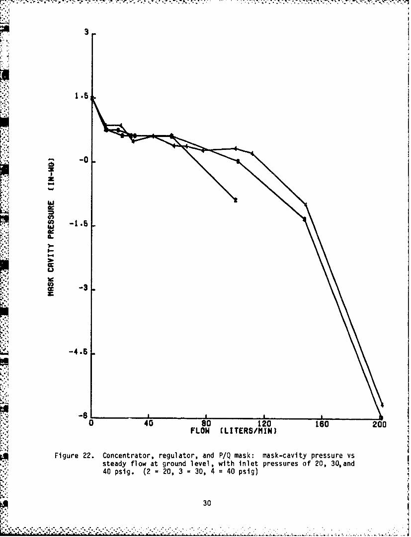
Figure 22 depicts mask-cavity pressure observed for various productflows under steady flow conditions (all tests were performed with a P/Q maskunless otherwise stated). The regulator delivered up to 50 I/min staticflow and maintained 1-in-wg safety pressure with inlet pressures as low as20 psig. Above 50 1/min steady product flow, higher inlet pressuresimproved regulator performance. A continuous flow of 200 1/mmn was obtainedwith inlet pressures above 30 psig.
A breathing machine that produced a sinusoidal breathing pattern wasused to test dynamic regulator performance. Figure 23 indicates the maximumand minimum mask-cavity pressures observed when peak inspiratory/expiratoryflow was varied from 30 to 200 1/mmn. Regulator performance was a functionof inlet pressure (set at 40 psig in Fig. 23), outlet peak flow, and rate ofchange in outlet flow. The breathing machine's tidal volume and frequencywere first set to obtain a breathing pattern of 30 1/mmn peak inspiratoryflow (Q peak), with a maximum rate of change in inspiratory flow (Q dot max)of 3 1/sec4. Different settings were then used to obtain peak flowý, andcorresponding makimum rate of change in flo Ys, of 110 I/min, 11 1/sec4; 1i0I/min, 15 I/sec4: and 200 I/min, 20 I/sec . Thus, Q dot max (in I/sec )equals Q peak/1O (in 1/min). Mask-cavity pressure swing, shown in Figure24, was the difference between maximum inspiratory and expiratory mask-cavity pressure.
As cabin altitude increased to approximately 20,000 feet, resistance tobreathing decreased as indicated in Figures 25 and 26. Figure 25 displaysthe mask-cavity mlnimum-and maximum-pressure curves with a breathin demand(minute volume) of 30 1/min peak flow and a Q dot max of 3 I/sect. Withbreathing demand at 200 1/mmn (Fig. 26), resistance to breathing was greaterthan with demand at 30 1/min.
As cabin altitude went above 38,000 feet, the regulator pressurebreathing schedule increased the mask-cavity pressure. Figure 27 shows thisrelationship with a steady flow of 50 1/min. Figure 28 data, obtained withdynamic breathing peak flow of 30 1/ min, shows the minimum and maximum maskpressure; the average of these pressures is shown in Figure 29. Figures 30and 31 are similar to Figures 28 and 29 but with peak flow set at 110 1/mmn.
29
• • ' •,• ; ., • '. •, " ' , ' , .,. , ,.' , ,,' . ./ . . •. , - . , ' - . •" . .. . , .. . -, . .- • , .- ,.. . , , ., . • , . ' . ' . - . . " •. .. -.. ' ,.
3
-0
1.5
S~z
to
cc- -
"•'P
• 3-3
-4.5
0 40 so 120 160 200FLOW (LITERS/MIN)
Figure 22. Concentrator, regulator, and P/Q mask: mask-cavity pressure vssteady flow at ground level, with inlet pressures of 20, 30,and40 psig. (2 = 20, 3 30, 4 = 40 psig)
30

4
z
W 2
cc
12
0 0so1016 0
PEKISPRTR FO LTESMN
-31

7
?j
. 4
3
2
0 1j0 . .. II
0 40 so 120 ISO 200PEAK INSPIRATORY FLOW (LITERS/MIN•)
Figure 24. Concentrator, regulator, And P/0 mask: mask-cavity pressureswing vs dynamic flow at ground level, with 40-psig inletpressure.
W 32
•."

3 '
2.51
2
z
CLJ
1;4 cc
an 3-/ef1dtmx
337
1'

B
SI6
" 5
7'
3
W
W 2
-2
w
S.-b-a
F-1
Ii
-2 0 5 10 15 20 25CABIN ALTITUDE (THOUSAND FEET)
Figure 26. Concentrator, regulator, and P/Q mask: mask-cavity pressure vsaltitude, with 40,-psig inlet pressure, 200-1/mmn dynamic Q -peak, and 20-1/sec2 Q dot max.
34

S, - - S S ° - o - - . - S '
17
15
'Si 13
z
.IU 7
cc
iJ.i"
40 s0
0 10 20 30 4CABIN ALTITUDE (THOUSAND FEET)
Figure 27. Regulator pressure breathing schedule" mask-cavity pressure vs
inpressurized cabin altitude, with 40-psig inlet pressure and
50-1/min steady flow.
4 35
....... ........ .............

20
i-
14
z
1.4]0-I 12
10 10
p8j
(II
"44
2t
:'-1
E SO
CABIN ALTITUDE (THOUSAND FEET)
Figure 28. Regulator pressure breathing schedule: mask-cavity pressure vsunpressurized cabin altitude, with 40-psig inlet pressure and ~30-1/mmn dynamic Q peak. (A maximum, B =minimum pressure)I
36
Fl I
,. - p ~ - . . .. J

20
14
z
W 12
'IL
10
L-
Uj 8
4
2
Figt~re 29. Rcyulator pressure breathing schedule: average mask-cavitypressure vs unpressurized cabin altitude, with 40-psig inletpressure and 30-1/mmn dynamic Q peak.
37

20
18
18
14
zZ"12
10
i,-
> 8
(gJ
Uj
4
2
0~4 s o . . _ ..
30 35 40 45
CRBIN ALTITUDE (THOUSAND FEET)
Figure 30. Regulator pressure breathing schedule: mask-cavity pressure vsunpressurized cabin altitude, with 40-psig inlet pressure and110-1/min dynamic Q peak. (A - maximum, B = minimum pressure)
38
t - .' ,• ' ' , " ,. :' . T, . " ," • ' . ' . ,. ' , " • " . . " " , "'. , " . " , "' , " . ' . " , - . " . '. , " . -" . - . ' " , . " " . .- ." .- , . - . - . . - ., ' . - " -_• . " - '.. " ..

20
18
18
0 14z
W 12
C,,
eL
.1r
� 4
0. J
2.
30 35 40 45 50
CABIN ALTITUDE (THOUSAND FEET)
Figure 31. Regulator pressure breathing schedule: average mask-cavitypressure vs unpressurized cabin altitude, with 40-psig inletpressure and 110-1/min dynamic Q peak.
39

-. .
w '
As the inlet air pressure cycles through the concentrator beds, theOBOGS product pressure simultaneously cycles. Peak pressure at the regula-tor inlet was approximately 38 psig, while the minimum pressure varied withproduct gas flow. Prior to OBOGS laboratory testing, there was concern thatminimum product pressure, or regulator inlet pressure, might be insufficientto operate the regulator. Also, if regulator inlet pressure dropped below10 psig, the BOS might be activated. Regulator inlet pressure was a func-tion of (1) OBOGS outlet gas pressure, (2) the length, diameter, and routingof the connecting line between the concentrator and regulator, and (3)product gas flow. Figure 32 shows the regulator outlet (product gas) flow,
mask-cavity pressure, and regulator inlet and outlet pressure when the peakconcentrator inlet pressure was 40 psig. With peak product flow of approxi-mately 150 1/min, the regulator received sufficient inlet gas pressure(23-38 psig) to operate correctly. A mask-cavity pressure swing from -1.0to +4.5 in-wg corresponded to a comparable swing in regulator outlet pres-sure. As the OBOGS concentrator flow alternated from bed to bed, the regu-lator inlet pressure cycled from 38 to 23 psig due to the intermittentpressurization of the beds. As product gas was delivered to the mask,corresponding reductions occurred in the regulator inlet pressure. Whenthese reductions synchronized with minimum concentrator outlet pressures,the resultant regulator inlet pressure was at a minimum.
The synchronizing effect is also demonstrated in Figure 33, where peakproduct flow was set at 200 1/min. On every fourth breath, product demandsynchronized with minimum concentrator outlet pressure. When this happened,regulator inlet pressure dropped to 15 psig, which was sufficiently low toaffect regulator performance. As the regulator attempted to deliver a 200-1/min breath in synchrony with minimum concentrator outlet pressure, theinspiratory mask-cavity pressure (-4 vs -3 in-wg) increased slightly. Thisoccurred because the regulator diaphragm had opened farther than usual tocompensate for the reduced regulator inlet pressure. The subsequent expira-tion therefore required an increase in mask-cavity pressure to overcome theproduct gas flow and open the expiratory valve. The result was an increasein expiratory resistance from 6 to 19 in-wg, and a reduction in peak flow
for these "restricted" breaths to about 185 1/min.
The synchronizing effect between product gas flow and concentrator out-let pressure did not degrade regulator performance with peak product flow upto 150 1/min. Only the highest product flow (200 1/min) produced a notice-
able change in mask-cavity pressures. Also, mask-cavity pressure increasedonly when the peak product flow coincided with minimum concentrator outletpressure. Our considered opinion is that this will occur infrequentlyduring normal operation; and even if it should occur, the pilot may feelonly a harmless, transitory puff of pressure in the mask cavity duringexpiration and may notice only a very mild restriction of inhalation for a
single breath.
40
......................

200
REG OUT 100 -
(1MIN) -*
- -... .......
MASK 0(IN-WG) ________ i
-25 ______________
'50 _ _ _ _ _ _
+E N 25 T-1luLi.:i___
(PIN-G) I .
-25
presur Ond 15 1/m- dynam- pea fo m inum nlet
I.-25
41

C.., 74
200
REG OUT 100 .::. ..... :1
(1MIN)
+25 7'zr m
P
K(IN-WG)......-25
5PI )0 111 : :-6 T_______.
... .... .. .-
A.n -.. --
-E N 25 I "T 11Figure~~~~~~~~~~~~~~~: 337ocnrtr euaoadms efrac ih201m
+252

Mask
Three masks--the United Kingdom P/Q and the USAF MBU-5/P and MBU-12/P--were tested with the other OBOGS components. Dynamic tests included flowrates from 20 to 200 I/min as indicated in Figure 34. Each mask gave simi-lar pressure-swing characteristics at the 20-1/mmn flow rate. However, aspeak flow increased, the P/Q mask exhibited a much lower resistance tobreathing. Up to 100 I/min, the expiratory mask-cavity pressure was similarfor all masks; however, the inspiratory pressure was much less in the P/Qmask. At higher flow rates (such as those experienced during speech or M-1maneuvers), the P/Q mask gave a much lower pressure swing than did theMBU-5/P or 12/P mask.
"16
I.-. I
l12i 129 4,
t5
1120.... .. I O18. t2CS/
'. I-I 1.2
-'. ' O
,~ue3. Compariso ofte-Qakwt th M:J12- ndMBI-/P msks
...... : ' , .
• . ii. . . 4 * ... .
2' ' " !1i ' " i... .. . .. ..
FLO (. / I N). •
Sfigure 34. Comparison of the PIQ mask with the MBU-121P and MBU-5/P masks.
• 43

Selector Valve/BOS
The OBOGS selector valve was tested to verify proper operation duringmanual and automatic switching between OBOG and BOS. During this test, theoxygen-low and selector-valve lights were monitored and the mask-cavitypressure and product gas composition were recorded while various malfunc-tions were simulated. Results of this test are shown in Table 1. Manualand automatic switching of the selector valve functioned as specified underall conditions. Caution-light symbology, however, was not completelystraightforward. When the selector valve was in the backup position, the SVyellow caution light stayed lst after the backup bottle was depleted (case4C, Table 1). Also, when the selector valve was in the OBOG position, theSV caution light did not illuminate when the system pressure was below 10pslg even though the BOS was supplying the breathing gas (case 2C). Theselector valve regulated BOS pressure from 1800 to 60 psig in accordancewith the OBOGS specification. Therefore, whenever the BOS was selected,mask-cavity pressure was not affected.
TABLE 1. F-16A ONBOARD OXYGEN GENERATING SYSTEM SWITCHOLOGY
Selector Lights Gasvalve OXY SV source Condition/Mal function
1 A OFF - - OBOG Normal; Bottle empty;DC off
B ON ON OBOG Low P02 ; Low pressure;Press-to-Test
2 A OBOG - - OBOG Cabin a+. < 31K; Bottleempty; D off
B ON BOS Cabin alt > 31KC ON - BOS Low pressure
D ON - OBOG Low P02
3 A AUTO OBOG Cabin alt < 25K; Bottleempty; DC off
B ON BOS Cabin alt > 25K
C ON ON BOS Low P0; Low pressure
4 A BU - ON BOS Normal
B ON ON BOS Low P02 ; Low pressure
C - ON OBOG 02 bottle empty
D - - BOS DC off .
44

Rapid Decompression Testing
Rapid decompression testing was conducted with the concentrator main-
tained at aircraft altitude and the cockpit-mounted components at cabin
chaberanda large accumulator opened quickly to allow rapid decompres-sion. Decompression time was controlled by adjusting the orifice size
between the two chambers. The deirompression time (delta t) was measuredfrom when the cabin altitude started to rise until 90% of the final aircraftaltitude was reached. Decompression testing was conducted with a breathing
p.. machine, brass mannequin head, and a P/Q mask, together with the cockpit-mounted components. During the decompression, peak mask-cavity pressure wasrecorded and plotted against 1/delta t (Fig. 35). During unmanned testing,rather large peak mask pressures occurred due to the experimental setup. Ajleakproof putty compound sealed the mask to the mannequin head, thus preven-ting the expanding gas from venting around the mask seal. Also, thebreathing machine and associated plumbing did not adequately represent thethis type of experimental setup was useful to verify proper operation of the
Vregulator during rapid decompressions. With a2ekro rnslms elexpanding gases in the regulator and mask supply hoses were forced to escapebackward through the regulator relief port, reducing the regulator outletpressure until the compensated mask expiratory valve could open and ventK expanding gas in the lungs and mask cavity. Figure 35 illustrates thelinear relationship between duration of decompression and peak mask-cavitypressure. This relationship did not depend on initial and final altitudebecause all decompressions represented a 5 psi differential between thecabin and aircraft pressures.
Acceleration Testing
gThe entire OBOGS was mounted in the USAFSAM centrifuge and tested withgloads up to +10 Gz, using both steady and dynamic product flows. The con-
centrator, selector valve, and regulator package were independently orien-ted with respect to the Gz vector while system parameters were recorded.The only component that demonstrated anyGz effect was the P/Q mask which :tended to leak around the expiratory valve under high-GZ loads. This effectwas strictly a mask phenomenon' and did not degrade OBOGS performance. No
other adverse effects were noted during acceleration testing.
I. .4
451

80I.W.
70
Iz8O
CLC
141
La1%500)
DINI.-
30
20
10 p i .. .
0 1 2 3 4 51 / DELTA T (SECmu-1)
Figure 35. Unmanned rapid decompression testing: peak mask-cavity pressurevs decompression time (1/delta t), with 40-psig inlet pressure.(initial/final altitudes (K ft): A ; 12/30, B = 16.8/40, C = 8/20)
46

~' 7-1- 7-
.4 MAN RATING
OBOGS nian rating consisted of having human subjects breathe from thesystem during altitude-chamber flights, rapid decompression test-Ing, andacceleration testing.
Altitude Testing
Five subjects were used for OBOGS altitude tests. The altitude profileincluded breathing at ground level, first while the subjects were at restand then while talking. The subjects also exercised at light and mediumwork loads on a bicycle ergometer, in silence and then with speech. Therest /exerc ise/speec h protocol was repeated at 8,000-ft altitude. Normalbreathing with speech was repeated at 22,000 feet and at 40,000 feet. Cabinaltitude was then reduced to 10,000 feet, where M-1 maneuvers wereperformed.
During these tests, mask-cavity pressure and product gas compositionand flow were recorded in addition to several other system and physiologicalparameters. The concentrator was supplied with 800C inlet air at 40 psig.Product gas composition stayed within the specified bounds (Fig. 36), andthe system automatically switched to BOS as cabin altitude exceeded 25,000 -
feet. Between 25,000 and 31,000 feet, the subjects could manually selectOBOGS product gas via the selector valve; above 31,000 feet, BOS gas wasautomnatically delivered to the subjects.
Figure 37 is a scatter diagram that indicates mask-cavity pressure as afunction of peak Inspiratory flow and altitude. As expected, .mask-cavitypressures increased with increasing product flows. The variation in maskpressure at any one product flow was due to the different breathing patternsand rates of change in flow for different subjects, which resulted fromdifferent types of activities; i.e., rest, exercise, speech, and M-1maneuvers. Variation in mask pressure was also due, in part, to the
I synchronizing effect between the concentrator and product-demand flow.
SIRapid Decompression Testing
Four subjects were used for rapid decompression testing.. The subjectswere placed in a decompressible altitude chamber with the OBOGS. regulator,selector valve, and BOS. The concentrator was placed in an altitude chamberthat was maintained at aircraft altitude. Two subjects underwent rapiddecompressions from 8,000 to 23,000 feet, and two from 16,800 to 40,000feet. These results are plotted in Figure 38. A comparison ofmanned -v s-unmanned rapid decompressions revealed that mask-cavity pressuresfor decompressions of similar duration were much lower in the manneddecompressions and were well within the desired mask-cavity limits. Becauseof human-safety considerations, the manned decompressions were of much lessduration than many of the unmanned decompressions.
47........................... -.

100 j
III90
8C
I,.-1
UB-.
- 70
Z3
* Icc
I--
2:1
U 60zC
404o I
30 , a0 a 8 s 24 32 40CRBIN ALTITUDE (THOUSAND FEET)
Figure 36. Human breathing: oxygen concentration vs cabin altitude with40-psig inlet pressure, 80 0C inlet temperature, and minutevolumes of 0-20, 20-40, and 40-60 1/min. (1 = 0-20, 3 =20-40, 5 40-60)
48
..................................".,.................•,1

20
18
12
12P
Q 4 0too
to 200
S
0 0 o ' osS,
00000
L 0•€ 2
cc
p..
-12-2 0-8 2
4
I4
-124
"-20 a a I
0 40 80 120 180 200PERK PRODUCT FLOW (L/MINi
Figure 37. Human breathin~g: peak mask-cavity pressure vs peak product
grun level and 8K, 22K, and 40K feet. (0 = 8K, 2 :22K,4r ~ =.. . ...lw wih4-sg4neOKrsur)n ai attd tK

13
12
I--
10
9 9
7I
0 9 i1.2 "1/DELTA T (SEC**-j)•
Figure 38. Human rapid decompression testing: peak mask-cavity pressure vs
decompression time (l/delta t), with 40-psig inlet pressure and'initial/final aircraft altitudes (K feet) of 8/23 and 16.8/40.(A 8/23, B 16.8/40)
/ 5 DET 50

Acceleration Testing
Four subjects were used for manned acceleration testing. All cockpitcomponents were mounted in the centrifuge in the normal cockpit orienta-tion. The concentrator was not installed in the centrifuge because of space
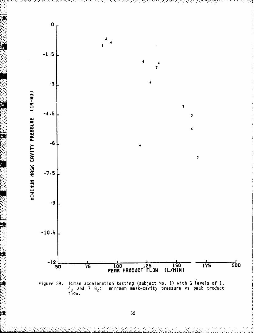
14kl limitations. The regulator was supplied with a bottled gas supply. Thesubjects were experienced centrifuge riders and were asked to perform M-1straining maneuvers as necessary to prevent grey-out. Data from three sub-jects (Figs. 39-41) indicate that the higher Gz loads required more forcefulM-1 manuevers and created sharper and deeper inhalation patterns with highrates of change in flow that resulted in more negative mask-cavity pres-sures. This does not imply that higher Gz loads affected the regulator.Comparing these data with human altitude data (Fig. 37) indicates thatsimilar peak product flows produce similar minimum mask-cavity pressures.For example, acceleration testing of the first two subjects produced inspi-ratory mask pressures of -4 to -11 in-wg for product flows of approximately170 1/mmn. Altitude testing produced inspiratory mask pressures of approxi-mately -2 to -16 in-wg for similar product flows. The variation in maskpressures (more noticeable with altitude testing) was due to the variationinrate of change in flow. The fourth subject in acceleration testing wasakdto breathe from the BOS supply. No difficulties were encountered, and
mask-cavity pressures were well within specified limits.
RECOMMENDATIONS
During laboratory testing of the F-16A OBOGS, spiveral items of interestwere noted and will be reported here with the intent that they be ccnsideredas recommendations for future improvements. Some suggestions would not becostly to incorporate into future F-16 OBOGS. The iUeas presented in thissection are not necessarily afterthoughts: some suggested features wereintentionally not incorporated in the flight demonstration program in order
to minimize aircraft modifications.
Concent rator
Overall, the F-16A concentrator performed in a satisfactory manner.*The most severe problem encountered in laboratory testing was failure of therotary valve's electric-motor phasing capacitor. This nonstandard capacitorhad to be replaced with a hermetically sealed capacitor rated at 115 VAC at400 Hz. In this single-phase system, the capacitor induced a phase differ-ence between the motor windings which produces torque. The capacitor couldbe eliminated by modifying the aircraft to make three-phase power availablefor the concentrator and by using a three-phase motor on the concentratorinlet valve. While an electrical modification of this type would be econom-ical in the short term, longer term consideration should be given to replac-ing the electric motor with a pneumatic valve assembly to drive the rotaryvalve with bleed air pressure.
51
.N . . .
0
44
-1.5
4 47
-3 4
z
-4.5
cc 7
E! M -74*5s
LU'
U,.
-9
I-...
P P:
E
1:12E-.9
-10,5
- 1 2 ,,ai a70"5 100 125 150 1'75 200
PERK PRODUCT FLOW (L/t1!N)
Figure 39. Human acceleration testing (subject No. 1) with G levels of 1,4, and 7 Gz: mi-nimum mask-cavity pressure vs peak, productflow.
52

I 0
4 3 7 1.- 1.5 6*
-3 ~
;JJ
F11
cc -4.5
-9
z a II
I - I A,,"
5100 125 IS 175 200PERK PRODUCT FLOW (L/MIN)
V
Figure 40. Human acceleration testing (subject No. 2) with G l evel s of 1,3, 5, 6, 7 , and 8 G minimum mask-cavity pressure vs peakproduct flow.
53
:'i I O 5 .• :-

,•I ,N . i
H 77 -;)
77
-3'
0z
-4.5
ca
I-
-10.z i:
-12
!--9
so 75 100 125 150 175 200PERK PRODUCT FLOW (L/MIN)
Figure 41., Human acceleration testing (subject No. 3) with G levels of 4and 7 Gz: minimum mask-cavity pressure vs peak productflow.
54 "4
• '1• •t' • • :• '" '•] •-: e'" •l~l ;: :l " • '• '•'r ll 2 • '•V '• ., ': ,- • "•, "• g lr :. ', ' •'''••" - •: a... ... •I ,.1

The F-16A concentrator did not have a vent in the inlet air supply.
Placing a vent in the inlet filter housing would allow any accumulation ofmoisture to escape overboard without entering the molecular sieve bed. Thisvent should be incorporated in future OBOGS concentrators to prevent waterloading of the zeolite beds, which slowly depresses oxygen output. Coordi-nation with the aircraft manufacturer can ascertain if a drain line shouldbe added to dump moisture outside the aircraft.
The product gas line diameter was minimally acceptable for concentratorinlet pressures of 40 psig. The combination of low inlet pressure and highproduct-gas consumption may affect regulator performance by increasingbreathing resistance. Increasing the product gas line diameter and/or add-ing a plenum in the cockpit, functionally located just prior to the regula-tor inlet port, can reduce this effect. This modification appears mandatoryfor the F-16B OBOGS to adequately supply two crewmembers.
Regul atorRegulator performance was satisfactory if concentrator inlet pressure
remained at or above 40 psig. The test-mask feature delivered 17-in-wgpressure which was considered high by the test subjects and somewhat uncom-fortable. Reduced test mask pressure (12 in-wg) would improve comfort with-out degrading the test procedure. Also, from an operational point of view,the system test button on the regulator package could be improved. Thebutton must now be held fully depressed for 20 seconds to complete thetest. When wearing gloves, the pilot cannot easily determine if the buttonis fully depressed, and 20 seconds is considered too long to dedicate forthis test during preflight. The button should be replaced with a detent-type button which the pilot can lock in the test position. The pilot canthen make other preflight checks and, when the indicator lights illuminate,can press the button again to return the system to normal. A lighted indi-cator might also be incorporated to verify switch position.
Another feature of the regulator that warrants improvement is thesafety pressure. Now the pilot must turn the selector valve off to removethe mask without activating the BOS. This is an unsafe practice as thepilot could forget to turn the selector valve back to normal after redonningthe mask. A provision on the regulator to turn off the safety pressurewould allow the pilot to remove the mask inflight without activating theBOS. It is unrealistic to ask the pilot not to remove the mask inflight;consequently, a selectable safety pressure switch is needed on theregulator.
Controller
In the laboratory test program, the controller had to be adjustedseveral times to obtain the desired product gas composition. Adjusting thecontroller is an iterative trial-and-error process. Multiple-adjustmentfeatures would be desirable: one to adjust the ground-level flow rate; oneto adjust the altitude at which the bleed flow begins to decrease; and oneto adjust the rate of bleed flow shutdown. These features may be techni-cally difficult to achieve, and some may not be necessary if the flighttest program provides a realistic range of concentrator inlet parameters.
55
i p I

However, the ECS tap point, and thus concentrator inlet temperature, maychange when the F-16 OBOGS goes into production. Also, the manufacturingprocess must maintain sufficient quality control in producing controllerdiaphragm springs to insure accurate oxygen concentration between control-lers. Therefore, a provision on the controller to satisfactorily adjust theproduct gas composition is recommended.
The controller used in this system is an almost completely pneumaticdevice. Other approaches should be investigated. Perhaps using an elec-tronic device or a mix between electronic and pneumatic devices may beadvantageous.
Selector Valve
Interpreting the selector-valve switch positions was difficult. Thisvalve could and probably should be simplified to avoid confusion for theuser. Two possibilities are available.
The first method involves using a two-position selector valve switchand a weight-on-wheels (touchdown bypass) switch. The two positions on theselector valve would be labeled OBOG and BOS. In the BOS position, 100%oxygen would supply the mask at all times, including ground operations, aslong as the BOS bottles were not depleted. In the OBOG position, concentra-tor product gas would supply the mask unless P02 fell below 195 mmHg, or
regulator inlet pressure fell below 10 psig, or cabin altitude rose above31,000 feet. On the ground, the weight-on-wheels switch would prevent theBOS from activating during a system test. With this method, as well as thenext, a normally closed solenoid switch could be used downstream of the BOSbottles to prevent BOS leakage. The solenoid would need manual/nonelectri-cal override for ground or power-off operations.
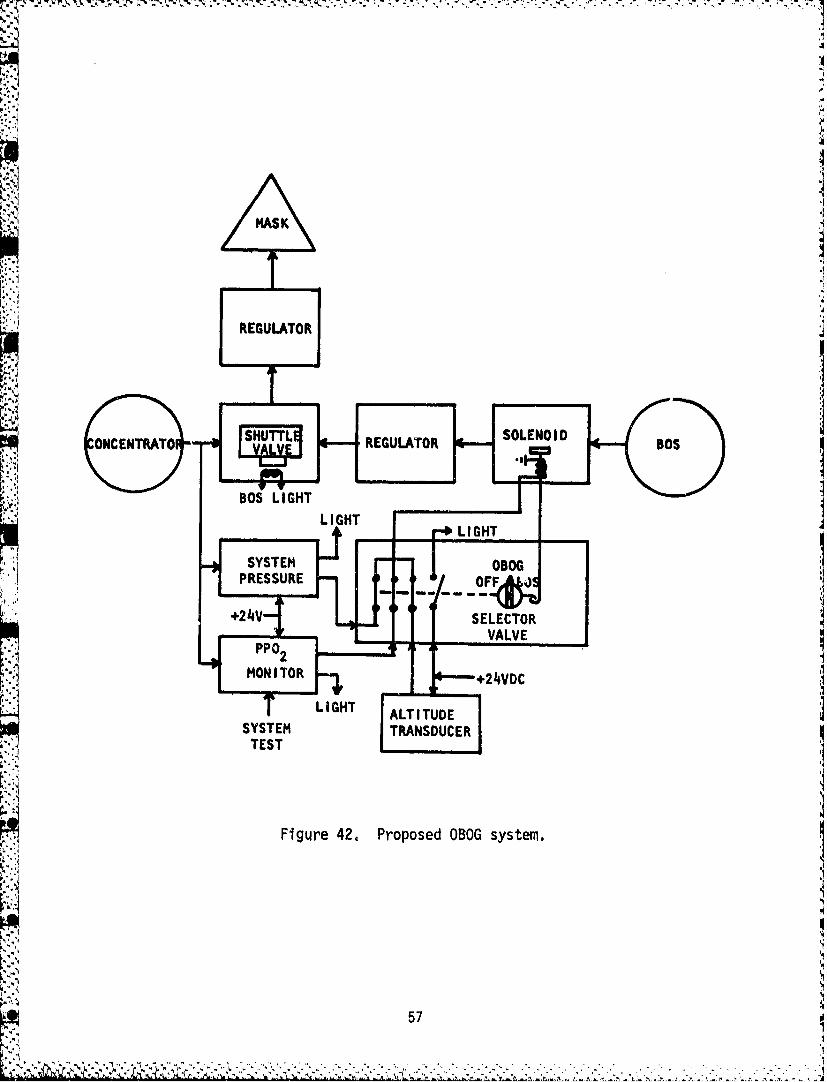
The second and preferred method of simplifying the selector valveinvolves replacing the weight-on-wheels switch with a third position on theselector valve, called the BOS OFF position (Fig. 42). With the selectorvalve in the OFF position, the BOS would be disengaged, thus allowing thesystem test to be activated on the ground without consuming BOS gas. TheOFF should be a push-to-turn position to prevent its inadvertent use inflight.
In the current OBOG position the selector valve will not automaticallyswitch the BOS if P02 falls below 195 mmHg. In this case if the pilot doesnot switch the selector valve to AUTO or BOS, and if P02 falls significantlybelow 195 mmHg, the pilot may become hypoxic. In other switch positions thesystem automatically switches to BOS; therefore, to be consistent, the sel-ector valve should switch to BOS if P02 falls below 195 mmHg in the OBOGposition.
As with the controller, perhaps a mix of electronic and pneumaticdevices may simplify construction of the selector valve.
56
•;''; !l' • ,•.-*W" ,":" 'i"• :" " •" " -" " : ,.• • C, • • : 'Z, ,': '",t' i L, '£,! "', .: a.A• 2,<, 'X , •u'.• ,J5 .•.; ' •" U •• .,•,,: "• ., .
4. i
MAS K
Am1
REGULATOR
ONCENRT luREUAO 4- S
SYTESTBO
PRSSR 10
Fiur 2.Prpse OOVsstm
+24V SLEC5O

Indicators
Several shortcomings were noted with the indicator lights. First, inconjunction with the selector valve nomenclature, is the interpretation ofthe indicators. The meaning of an illuminated indicator light is difficultto completely translate (reference Table 1). The light on the selectorvalve should be known as a BOS light and should illuminate only when 100%oxygen is supplied to the mask. The BOS light should not illuminate justbecause the selector valve is in the BOS position, i.e., when the selectorvalve is at BOS but the BOS bottle is empty. Also, if 100% oxygen is beingsupplied to the pilot, the light must always illuminate (contrary to thepresent condition when the selector valve is in the OBOG position and cabinaltitude is above 31,OuO feet). A magnetic switch placed on the shuttlevalve to sense BOS flow could activate the BOS light. Also, the BOS lighton the selector valve needs to be relocated. The selector valve is locatedbehind the control stick, so the light is not visible to the pilot; it alsointerferes with the knob on the selector valve. Mounting the BOS light
directly above the BOS pressure gauge would direct the pilot's attentiontoward BOS pressure when the light illuminates. This would reinforce theneed to monitor BOS pressure when it is in use. The F-16 instrument panelhas ample room for the light in this position.
The OXY LOW light should be relabeled as OBOG, to indicate an OBOGproblem. This light now illuminates due to low PO2 or low regulator inlet
pressure. A single light cannot indicate which malfunction exists; perhapstwo lights may be necessary.
During the press-to-test system, all indicators should illuminate.
Miscellaneous
As the flight test program proceeds, several other recommendations maybecome apparent. Any change must not interfere with the integrity of theBOS. The BOS must be made leakproof, which may require hard line tubing inlieu of flexible tubing from the BOS manifold to the selector valve. Theselector valve must be able to seal the BOS and preclude its frequentservicing.
CONCLUSIONS
The F-16A OBOGS is a successful system which promises to overcome alllox shortcomings--the hazards of storing and handling, the expense andlogistics inherent with lox, the cost of stockpiling and replacing lox con-vertors and ground carts, the unacceptable service delays which increaseturnaround time in wartime environments, and possible limits in mission dur-ation due to the limited onboard quantity of lox.
Laboratory testing proved the equipment, built by Clifton Precisionaccording to USAFSAM specifications, to be adequate for flight testing.
Adoption of the laboratory test and flight test recommendations willensure that OBOGS will further enhance the mission of the F-16 aircraft.
58
-. > -*I.- ' - - ..

DEPARTMENT OF THE AIR FORCEARMSTRONG LABORATORY (AFMCJ
BROOKS AIR FORCE BASE. TEXAS
5Feb97
MEMORANDUM FOR DEFENSE TECHNICAL INFORMATION CENTER (DTIC)
FROM: AL/XPPL2509 Kennedy CircleBrooks AFB TX 78235-5118
SUBJECT: Change in Distribution Statement for USAFSAM-TR43-27, AD-B076 849
1. The document listed above has been reviewed by the Public Affairs Office, Brooks Air Force Base,Texas and has been changed from limited distribution to distribution A, unlimited release (see attachment,AL/XPPL 21 Jan 97 Ltr).
2. Please change the distribution statement at DTIC and make available to NTIS.
JUDY'A. BRYANTAL STINFO OFFICER
Attachment:AL/XPPL 21 Jan 97 Ltr
,9...0o°

DEPARTMENT OF THE AIR FORCEARMSTRONG LABORATORY (AFMC)
BROOKS AIR FORCE BASE TEXAS
21 Jan 97
MEMORANDUM FOR AL/XP (Dr. Miller)AL/XPPLIN TURN
FROM: AL/XPPL
SUBJECT: AL/AO Request for Release of Document to Czech Republic
1. AL/AO is requesting to release the attached report (USAFSAM-TR-83-27 to the CzechRepublic. This report has a Distribution limitation (as of 1983); however, the information may nolonger need protection since it is 14 years. At the time of its publication, Capt Thomas Horch wasproject engineer and Dr. Richard L. Miller was his supervisor.
2. As former supervisor of the original project engineer, request your review of this report andrecommendation for its release to the Czech republic. Request you also review for possibledowngrading from "Unclassified-Limited" (export controlled) to "Approval for public release." If youwish to downgrade it, we will send it to Public Affairs for review and approval. Please try tocomplete your review and return by 7 Feb 97.
.. If you have questions, please call--ext 5495. Thank you,
JUDY A. BRYANForeign Disclosure Officer
Atch:USAFSAM-TR-83-27
APPROVED FOR RELEASE TO CZECH REPUBLIC or NOT RELEASABLE
RICHARD L. MILLER, PhDDeputy Director, Plans
"PPROVED FOR DOWNGRADING TO PUBLIC DOMAN or NOT TO BEDOWNGRADED
RICHARD L. MILLER, PhDDeputy Director, Plans
(You can approve both if you wish.)
i , 7-